WO2016093076A1 - 波長変換部材及び発光装置 - Google Patents
波長変換部材及び発光装置 Download PDFInfo
- Publication number
- WO2016093076A1 WO2016093076A1 PCT/JP2015/083313 JP2015083313W WO2016093076A1 WO 2016093076 A1 WO2016093076 A1 WO 2016093076A1 JP 2015083313 W JP2015083313 W JP 2015083313W WO 2016093076 A1 WO2016093076 A1 WO 2016093076A1
- Authority
- WO
- WIPO (PCT)
- Prior art keywords
- phosphor
- light
- wavelength conversion
- conversion member
- color
- Prior art date
- Legal status (The legal status is an assumption and is not a legal conclusion. Google has not performed a legal analysis and makes no representation as to the accuracy of the status listed.)
- Ceased
Links
Images






Classifications
-
- C—CHEMISTRY; METALLURGY
- C09—DYES; PAINTS; POLISHES; NATURAL RESINS; ADHESIVES; COMPOSITIONS NOT OTHERWISE PROVIDED FOR; APPLICATIONS OF MATERIALS NOT OTHERWISE PROVIDED FOR
- C09K—MATERIALS FOR MISCELLANEOUS APPLICATIONS, NOT PROVIDED FOR ELSEWHERE
- C09K11/00—Luminescent materials, e.g. electroluminescent or chemiluminescent
- C09K11/02—Use of particular materials as binders, particle coatings or suspension media therefor
-
- C—CHEMISTRY; METALLURGY
- C09—DYES; PAINTS; POLISHES; NATURAL RESINS; ADHESIVES; COMPOSITIONS NOT OTHERWISE PROVIDED FOR; APPLICATIONS OF MATERIALS NOT OTHERWISE PROVIDED FOR
- C09K—MATERIALS FOR MISCELLANEOUS APPLICATIONS, NOT PROVIDED FOR ELSEWHERE
- C09K11/00—Luminescent materials, e.g. electroluminescent or chemiluminescent
- C09K11/08—Luminescent materials, e.g. electroluminescent or chemiluminescent containing inorganic luminescent materials
- C09K11/61—Luminescent materials, e.g. electroluminescent or chemiluminescent containing inorganic luminescent materials containing fluorine, chlorine, bromine, iodine or unspecified halogen elements
- C09K11/615—Halogenides
- C09K11/616—Halogenides with alkali or alkaline earth metals
-
- C—CHEMISTRY; METALLURGY
- C09—DYES; PAINTS; POLISHES; NATURAL RESINS; ADHESIVES; COMPOSITIONS NOT OTHERWISE PROVIDED FOR; APPLICATIONS OF MATERIALS NOT OTHERWISE PROVIDED FOR
- C09K—MATERIALS FOR MISCELLANEOUS APPLICATIONS, NOT PROVIDED FOR ELSEWHERE
- C09K11/00—Luminescent materials, e.g. electroluminescent or chemiluminescent
- C09K11/08—Luminescent materials, e.g. electroluminescent or chemiluminescent containing inorganic luminescent materials
- C09K11/77—Luminescent materials, e.g. electroluminescent or chemiluminescent containing inorganic luminescent materials containing rare earth metals
- C09K11/7715—Luminescent materials, e.g. electroluminescent or chemiluminescent containing inorganic luminescent materials containing rare earth metals containing cerium
- C09K11/7721—Aluminates
-
- C—CHEMISTRY; METALLURGY
- C09—DYES; PAINTS; POLISHES; NATURAL RESINS; ADHESIVES; COMPOSITIONS NOT OTHERWISE PROVIDED FOR; APPLICATIONS OF MATERIALS NOT OTHERWISE PROVIDED FOR
- C09K—MATERIALS FOR MISCELLANEOUS APPLICATIONS, NOT PROVIDED FOR ELSEWHERE
- C09K11/00—Luminescent materials, e.g. electroluminescent or chemiluminescent
- C09K11/08—Luminescent materials, e.g. electroluminescent or chemiluminescent containing inorganic luminescent materials
- C09K11/77—Luminescent materials, e.g. electroluminescent or chemiluminescent containing inorganic luminescent materials containing rare earth metals
- C09K11/7766—Luminescent materials, e.g. electroluminescent or chemiluminescent containing inorganic luminescent materials containing rare earth metals containing two or more rare earth metals
- C09K11/7774—Aluminates
-
- H—ELECTRICITY
- H10—SEMICONDUCTOR DEVICES; ELECTRIC SOLID-STATE DEVICES NOT OTHERWISE PROVIDED FOR
- H10H—INORGANIC LIGHT-EMITTING SEMICONDUCTOR DEVICES HAVING POTENTIAL BARRIERS
- H10H20/00—Individual inorganic light-emitting semiconductor devices having potential barriers, e.g. light-emitting diodes [LED]
- H10H20/80—Constructional details
- H10H20/85—Packages
- H10H20/851—Wavelength conversion means
- H10H20/8511—Wavelength conversion means characterised by their material, e.g. binder
- H10H20/8512—Wavelength conversion materials
-
- H—ELECTRICITY
- H10—SEMICONDUCTOR DEVICES; ELECTRIC SOLID-STATE DEVICES NOT OTHERWISE PROVIDED FOR
- H10H—INORGANIC LIGHT-EMITTING SEMICONDUCTOR DEVICES HAVING POTENTIAL BARRIERS
- H10H20/00—Individual inorganic light-emitting semiconductor devices having potential barriers, e.g. light-emitting diodes [LED]
- H10H20/80—Constructional details
- H10H20/85—Packages
- H10H20/851—Wavelength conversion means
- H10H20/8511—Wavelength conversion means characterised by their material, e.g. binder
- H10H20/8512—Wavelength conversion materials
- H10H20/8513—Wavelength conversion materials having two or more wavelength conversion materials
-
- H—ELECTRICITY
- H10—SEMICONDUCTOR DEVICES; ELECTRIC SOLID-STATE DEVICES NOT OTHERWISE PROVIDED FOR
- H10H—INORGANIC LIGHT-EMITTING SEMICONDUCTOR DEVICES HAVING POTENTIAL BARRIERS
- H10H20/00—Individual inorganic light-emitting semiconductor devices having potential barriers, e.g. light-emitting diodes [LED]
- H10H20/80—Constructional details
- H10H20/85—Packages
- H10H20/851—Wavelength conversion means
- H10H20/8511—Wavelength conversion means characterised by their material, e.g. binder
-
- Y—GENERAL TAGGING OF NEW TECHNOLOGICAL DEVELOPMENTS; GENERAL TAGGING OF CROSS-SECTIONAL TECHNOLOGIES SPANNING OVER SEVERAL SECTIONS OF THE IPC; TECHNICAL SUBJECTS COVERED BY FORMER USPC CROSS-REFERENCE ART COLLECTIONS [XRACs] AND DIGESTS
- Y02—TECHNOLOGIES OR APPLICATIONS FOR MITIGATION OR ADAPTATION AGAINST CLIMATE CHANGE
- Y02B—CLIMATE CHANGE MITIGATION TECHNOLOGIES RELATED TO BUILDINGS, e.g. HOUSING, HOUSE APPLIANCES OR RELATED END-USER APPLICATIONS
- Y02B20/00—Energy efficient lighting technologies, e.g. halogen lamps or gas discharge lamps
Definitions
- the present invention is a wavelength conversion member capable of greatly improving the color rendering of a light emitting device using a blue light emitting diode (LED) used for general illumination, a backlight light source, a headlight light source, and the like, And a light emitting device using the same.
- LED blue light emitting diode
- the light emitting diode is one of the most efficient illumination light sources among currently available light sources.
- white light-emitting diodes white LEDs
- CCFL Cold Cathode Fluorescent Lamp
- halogen lamps etc. due to their high efficiency.
- a white LED Light Emitting Diode
- a blue light emitting diode blue LED
- a phosphor that emits light having a longer wavelength, for example, yellow or green, by blue light excitation. Is widely used.
- a resin or glass mixed with a phosphor is coated on the upper surface of the blue LED element to seal the LED element, and part or all of the blue light emitted from the LED element is phosphor.
- the one that adopts a method for obtaining pseudo white light by converting the wavelength in the above, that is, the one in which the LED element and the phosphor are integrated is the mainstream.
- a resin or glass wavelength conversion member mixed with a phosphor is separated from the sealing material of the blue LED element, and is arranged in front of the light emitting direction of the LED element.
- the output of the LED element is high, and the characteristics of the phosphor are affected by the heat generated by the light emitting part.
- Such a method of separating the LED element and the wavelength conversion member is called a “remote phosphor method” and has been studied rapidly in recent years.
- the remote phosphor method has advantages as a practical lighting fixture such as an improvement in overall color unevenness and extremely small variations during mass production.
- yellow light emitting phosphor particles, green light emitting phosphor particles, and further red light emitting phosphor particles are dispersed in a resin or glass, or these phosphors are dispersed on the surface of a transparent substrate.
- the applied wavelength conversion member is arranged in front of the light source LED.
- a typical phosphor used for such a remote phosphor type wavelength conversion member a cerium activated yttrium represented by Y 3 Al 5 O 12 : Ce 3+ or Y 3 Al 5 O 12 : Ce 3+ is used.
- Examples include an aluminum garnet phosphor (YAG phosphor), a cerium activated lutetium aluminum garnet phosphor (LuAG phosphor) represented by Lu 3 Al 5 O 12 : Ce 3+ or Lu 3 Al 5 O 12 : Ce 3+.
- Other phosphors include (Y, Gd) Al 5 O 12 : Ce 3+ , TbAl 5 O 12 : Ce 3+ , (Sr, Ca, Ba) 2 SiO 4 : Eu 2+ , ⁇ -SiON : Eu 2+ and the like.
- a phosphor such as CaSiN 3 : Eu 2+ and Sr—CaSiN 3 : Eu 2+ may be used in combination with the above phosphor.
- the average color rendering index Ra of most conventional light emitting devices evaluated for light emission of white LEDs by such a color rendering property evaluation method cannot be said to be better than that of existing lighting such as conventional incandescent bulbs and fluorescent lamps.
- the special color rendering index R9 using the red color chart R9 tends to be low.
- Natural light which is the standard for the emission color, changes in color tone from pale light to reddish light depending on the altitude of the sun. This is completely related to the relationship between the temperature and emission color when an object is red hot.
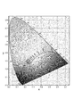
- the chromaticity can be drawn as a black body radiation orbit on the xy chromaticity diagram (CIE 1931) as shown in FIG.
- the light emission of the LED is not limited to the range of the black-body radiation orbit because the light emission principle is different from that due to thermal radiation like natural light.
- the chromaticity coordinates of the LED's emission are far from the black body radiation orbit, the light quality is felt green or magenta even if the color reproduction when illuminated is good. Give an unnatural impression. Therefore, in the white LED, the emission color is usually adjusted so that the chromaticity coordinates of the emission are on the black body radiation orbit. That is, in the LED light emitting device for illumination, the color rendering index, which is the index of color reproducibility (color rendering) described above, in particular, the average color rendering index Ra obtained from the color rendering indices R1 to R8, and the special color rendering evaluation. It can be said that the color rendering property is excellent when the number R9 is high and the chromaticity coordinates of the light emission are on the black body radiation orbit.
- the deviation between the emission color of the LED light-emitting device and the black body radiation orbit is called color deviation, and it should be quantified as the deviation duv ( ⁇ uv) between the black body radiation orbit and the illumination light in the uv chromaticity diagram (CIE 1960). Can do.
- the uv chromaticity diagram is used when obtaining the color deviation because the uv chromaticity diagram is set so that the distance of each arbitrary point is equal to the perceived color difference, which is convenient for quantification of the color deviation. Because.
- the absolute value of duv should be as small as possible, and the absolute value of duv is preferably 0.001 or less.
- color temperature (CCT) of the illumination light light with a high color temperature of light emission, for example, light of 6000 K gives a cold impression with a strong contrast.
- light with a low color temperature for example, 3000K, is known to provide a warm and peaceful sensation, and when using a luminaire, illumination with a color temperature in accordance with the environment is selected.
- the inventors first use a mixed phosphor of a manganese-activated double fluoride phosphor (KSF phosphor) represented by K 2 SiF 6 : Mn 4+ and a YAG phosphor as the phosphor.
- KSF phosphor manganese-activated double fluoride phosphor
- a YAG phosphor a YAG phosphor
- Ra a remote phosphor LED light emitting device having a high special color rendering index Ra was developed.
- the Ra value exceeds 90, and a good emission color excellent in red reproducibility can be obtained as compared with a conventional white LED.
- the color temperature range where the Ra value is the largest is slightly lower than 4000K, and when trying to obtain light emission with an Ra value exceeding 90 in the color temperature range above 4000K, the color deviation duv is slightly negative.
- the value of Ra is even in a region where the color temperature exceeds 6500K. Although more than 90 and good light emission excellent in red reproducibility can be obtained as compared with the conventional white LED, in this case, the color reproducibility in the low color temperature range is inferior.
- the combination of the KSF phosphor and the LuAG phosphor a good color reproducibility can be obtained when the color temperature is high, but as in the case of using a mixed phosphor of the KSF phosphor and the YAG phosphor, The color rendering properties of the luminescent colors were still not sufficient.
- the present invention has been made in view of the above circumstances, and is used when a color temperature range of 4000 to 6500 K, which is a general color temperature range of white to daylight, particularly about 5000 K, is used with a blue LED.
- Another object of the present invention is to provide a wavelength conversion member capable of giving good color rendering properties and emitting light with a small color deviation duv in this color temperature range, and a light emitting device using the same.
- the inventors have obtained a manganese-activated double-fluorine in order to obtain light emission having a good color rendering property and a small color deviation at a color temperature in the color temperature range of about 5000K.
- a yellow phosphor to be combined with a fluoride phosphor (KSF phosphor) is studied, and by combining the KSF phosphor with a cerium activated lutetium yttrium aluminum garnet phosphor (LuYAG phosphor), good light emission can be obtained. I found out.
- the LuYAG phosphor is a complex oxide phosphor generally represented by (Y, Lu) 3 Al 5 O 12 : Ce 3+ , and yttrium sites in a widely known yttrium aluminum garnet oxide crystal are formed by lutetium. Further, the phosphor is activated by cerium to obtain a phosphor. In this phosphor, the emission color of fluorescence can be adjusted by adjusting the amount of lutetium to be substituted and the amount of cerium to be activated, and the emission color of this phosphor has a wavelength of 420 to 490 nm. When blue light is used as excitation light, yellow-green fluorescence having a broad emission spectrum with a dominant wavelength of 563 to 570 nm suitable for combination with the KSF phosphor is emitted.
- the present inventors have used a specific LuYAG phosphor together with a KSF phosphor, dispersed in a thermoplastic resin to obtain a wavelength conversion member, Is arranged on the optical axis of the LED light source that emits light containing a blue light component, particularly at a position separated from the LED light source as a remote phosphor system, and in a color temperature range of about 5000 K, a good color rendering property is achieved.
- a light-emitting device that emits light with a small color deviation duv in particular, a light-emitting device that gives a good emission color in a color temperature range of 4000 to 6500 K, which is important in an illumination device that emits white light, It came to make this invention.
- a cerium activated lutetium yttrium aluminum garnet phosphor (B) The following composition formula (2) K 2 (Si 1-x Mn x ) F 6 (2) (Wherein x is a positive number of 0.001 or more and 0.3 or less), and contains a manganese-activated silicon double fluoride phosphor that emits red light when excited with blue light, (B) The wavelength conversion member characterized by containing the fluorescent substance of a component with the mass ratio of 1 time or more and 5 times or less with respect to the fluorescent substance of (A) component.
- the appearance color of the phosphor of the component (A) is such that the a * value of the chromaticity coordinates in the CIE L * a * b * color system is ⁇ 23.0 or more and ⁇ 21.0 or less, and the b * value is It is 87.0 or more and 97 or less,
- the thermoplastic resin is one or two selected from the group consisting of polyolefin, polystyrene, styrene copolymer, fluorine resin, acrylic resin, nylon, polyester, polyethylene terephthalate, polycarbonate, vinyl chloride resin, and polyether resin.
- a blue LED light source that emits light containing a blue light component having a peak wavelength of 440 to 470 nm, and the wavelength conversion according to any one of [1] to [3] disposed on the optical axis of the blue LED light source And a light emitting device.
- the emission color is characterized in that, in the chromaticity coordinates of the xy chromaticity diagram (CIE 1931), x is 0.3100 or more and 0.3850 or less, and y is 0.3190 or more and 0.3790 or less. 4] The light-emitting device of description.
- a light-emitting device that emits white light suitable for an illumination device that exhibits good color rendering in a color temperature range of 4000 to 6500 K, which is a color temperature range of white to daylight, and has a small color deviation duv. Can be provided.
- FIG. 4 is a diagram showing the intensity of emission (fluorescence) at a wavelength of 550 nm by excitation light having a wavelength of 420 to 490 nm of the LuYAG phosphor, YAG phosphor and LuAG phosphor.
- the emission (fluorescence) spectrum of LuYAG phosphor, YAG phosphor, and LuAG phosphor when blue light having a wavelength of 450 nm, which is a general main wavelength of blue LEDs, is used as excitation light is shown.
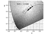
- FIG. 6 is a diagram showing coordinates on an xy chromaticity diagram of light emission of the light emitting devices of Examples 1 to 6.
- FIG. 6 is a graph showing the relationship between the color temperature of light emission and the average color rendering index Ra of the light emitting devices of Examples 1 to 6 and Comparative Examples 1 to 7. It is a figure which shows the relationship between the color temperature of light emission, and the special color rendering index R9 of the light-emitting device of Examples 1-6 and Comparative Examples 1-7. It is a figure which shows the black-body radiation orbit on xy chromaticity diagram (CIE1931).
- the wavelength conversion member of the present invention includes a thermoplastic resin and a phosphor, and the wavelength conversion member is a resin molded body in which a phosphor is dispersed in a thermoplastic resin.
- a phosphor a particulate or powdered material is preferably used.
- thermoplastic resin having a short solidification time at the time of molding is used as the base material into which the phosphor is kneaded.
- Thermosetting resin with reaction curing such as silicone resin requires several tens of minutes to several hours to cure from a fluid state, and the phosphor settles or aggregates before curing, It is difficult to disperse various phosphors simultaneously and uniformly in the resin.
- the thermosetting resin is cured, the phosphor content cannot be readjusted. Therefore, the thermosetting resin is fixed at the phosphor content initially set and cannot be changed.
- thermoplastic resin it is possible to mix a plurality of types of phosphors in order, or to mix them together into a single resin, and then to combine them together. It cannot be adopted. Therefore, as will be described later, a thermoplastic resin is more suitable in the present invention using two or more phosphors having different emission colors.
- thermoplastic resin a resin having high optical characteristics when phosphors are mixed, high chemical resistance to alkali, and excellent moisture resistance is preferable.
- the thermoplastic resin used in the wavelength conversion member of the present invention includes polyolefins such as polyethylene and polypropylene, polystyrenes such as general-purpose polystyrene (GPPS), styrene / maleic acid copolymer, styrene / methyl methacrylate copolymer.
- GPPS general-purpose polystyrene
- styrene / maleic acid copolymer styrene / methyl methacrylate copolymer.
- thermoplastic resins are selected as the resin for kneading the phosphor.
- polyolefin, polystyrene, styrene copolymer and acrylic resin are preferable.
- the phosphor can be mixed in a wide content range, and the resin and the phosphor. Is particularly preferable because of its low decomposition and deterioration.
- the thermoplastic resin used in the present invention is preferably an amorphous transparent resin because it is used for optical purposes. However, if the attenuation of the total amount of transmitted light is sufficiently small, the linear transmittance need not be high.
- the processing characteristics of the resin those which can be injection-molded with a melt flow rate (MFR) defined by JIS K 7210 of about 5 to 30 g / 10 min are preferable.
- the phosphor contained in the wavelength conversion member of the present invention includes a cerium-activated lutetium yttrium aluminum garnet phosphor (LuYAG phosphor) as the component (A), and a manganese-activated siliceous double fluoride phosphor (B) as the component (B).
- CeYAG phosphor cerium-activated lutetium yttrium aluminum garnet phosphor
- B manganese-activated siliceous double fluoride phosphor
- Two types of phosphors KSF phosphors are included as essential components.
- the cerium activated lutetium yttrium aluminum garnet phosphor (LuYAG phosphor) as the component (A) has the following composition formula (1): (Y 1- ⁇ - ⁇ Lu ⁇ Ce ⁇ ) 3 Al 5 O 12 (1) (In the formula, ⁇ is a positive number of 0.3 to 0.8, and ⁇ is a positive number of 0.01 to 0.05.)
- a phosphor that emits yellow-green light when excited with blue light, and has a structure in which part of the constituent elements Lu, Y, or both sites are substituted with trivalent cerium (Ce 3+ ). have.
- the LuYAG phosphor may be expressed as (Y, Lu) 3 Al 5 O 12 : Ce or (Y, Lu) 3 Al 5 O 12 : Ce 3+ .
- the LuYAG phosphor is excited by blue light having a wavelength of 420 to 490 nm, preferably 440 to 470 nm, and emits yellow-green light having a broad emission spectrum having a dominant wavelength of 563 to 570 nm.
- the dominant wavelength is a dominant wavelength and is the wavelength that is most strongly felt in light emission.
- ⁇ is in the range of 0.3 to 0.8.
- the value of ⁇ which is the ratio of Ce as the activation element, is set to 0.01 or more and 0.05 or less. This is because, when ⁇ is less than 0.01, the luminous efficiency of the LuYAG phosphor is reduced. On the other hand, when ⁇ exceeds 0.05, the phosphor is heated by the production of the LuYAG phosphor. This is because the particles are fused with each other and it becomes difficult to knead them into the thermoplastic resin.
- ⁇ and ⁇ for example, when ⁇ is 0.02, ⁇ is preferably in the range of about 0.4 to 0.6.
- the LuYAG phosphor of the component (A) of the present invention has a diffraction angle 2 ⁇ in the X-ray diffraction by Cu K ⁇ 1 line (characteristic X-ray having a wavelength of about 1.54060 mm) of 52.9 degrees or more and 53.2 degrees or less. Those having a diffraction peak inside are preferred.
- the LuYAG phosphor having a diffraction peak within this angle range has a garnet crystal structure, like the YAG phosphor and the LuAG phosphor, and in particular, the (444) plane spacing is 1.720 to 1 or more. It is characterized by being 728 mm or less.
- the LuYAG phosphor of the component (A) of the present invention has an appearance color of a * value of chromaticity coordinates in the CIE L * a * b * color system of ⁇ 23.0 or more and ⁇ 21.0 or less, b *.
- a value of 87.0 or more and 97 or less is preferable.
- the value of the lightness L * in the L * a * b * color system is 0.104 or more and 0.107 or less.
- the LuYAG phosphor having such a diffraction peak or appearance color and the KSF phosphor of the component (B) described later are used as a wavelength conversion member, and this wavelength conversion member emits blue light having a predetermined wavelength.
- the color temperature range from 4000 to 6500K which is the color temperature range from white to daylight, especially in the color temperature range of around 5000K (for example, 4500 to 5500K), exhibits good color rendering and color deviation.
- a light emitting device that emits light with a small duv can be obtained.
- FIG. 1 is a diagram showing an X-ray diffraction profile of a LuYAG phosphor by Cu K ⁇ 1 line. Unlike the X-ray diffraction profiles of the YAG phosphor, the LuAG phosphor, and the mixed phosphor of the YAG phosphor and the LuAG phosphor, the LuYAG phosphor of the present invention is 52.9 degrees or more. It has a specific diffraction peak within a range of 53.2 degrees or less.
- FIG. 2 is a graph showing the intensity of light emission (fluorescence) at a wavelength of 550 nm by excitation light having a wavelength of 420 to 490 nm of the LuYAG phosphor, YAG phosphor and LuAG phosphor. As shown in FIG. 2, the utilization factor of the excitation light of the LuYAG phosphor for each wavelength is different from both the YAG phosphor and the LuAG phosphor.
- FIG. 3 shows emission (fluorescence) spectra of LuYAG phosphor, YAG phosphor and LuAG phosphor when blue light having a wavelength of 450 nm, which is a general main wavelength of blue LEDs, is used as excitation light.
- the emission spectrum pattern by excitation of the LuYAG phosphor of the present invention at the main wavelength of the blue LED is also different from both the YAG phosphor and the LuAG phosphor.
- the excitation characteristics and fluorescence emission characteristics of the LuYAG phosphor of the present invention are different from those of the YAG phosphor and the LuYAG phosphor, and the present invention has the above-described X-ray diffraction peak (crystal structure) and further the appearance color.
- the above-described characteristic excitation characteristics and fluorescence emission characteristics of the LuYAG phosphors are excellent color rendering properties and color deviation duv in the combination of the LuYAG phosphor of the present invention and the KSF phosphor of the component (B) described later. Has brought.
- the LuYAG phosphor used in the present invention can be manufactured using a plasma melting method.
- the plasma melting method instantaneously melts and solidifies a raw material powder that has been granulated in advance with a high-temperature plasma flame, so that amorphous particles in which constituent elements are uniformly mixed can be obtained without being limited by the solid solubility limit of the elements. It is a method that can be obtained.
- the LuYAG phosphor suitable for the present invention can be produced, for example, by the following method.
- a slurry of fine powder of alumina (Al 2 O 3 ) and other raw material elements, that is, oxides of yttrium, lutetium, and cerium, for example, fine powder of yttrium-lutetium-cerium coprecipitated oxide is used as a raw material.
- Particles granulated to a particle diameter of 5 to 65 ⁇ m are melted, partially reduced, and solidified by argon plasma containing hydrogen gas, for example, 1 to 10 mol% hydrogen gas. Further, the obtained amorphous particles are heated at 1,200 to 1,600 ° C.
- Crystallized phosphor particles can be obtained by applying heat treatment for 3 to 6 hours and then cooling so that the average cooling rate up to 1,000 ° C. is 5 ° C./min or more.
- an inert gas for example, argon gas
- hydrogen gas for example, 0.5 to 3 mol% of hydrogen gas.
- Crystallized phosphor particles can be obtained by applying heat treatment for 3 to 6 hours and then cooling so that the average cooling rate up to 1,000 ° C. is 5 ° C./min or more.
- the reason why the LuYAG phosphor suitable for the present invention can be obtained by the above-described method is not particularly limited, but the solidification rate of the melted particles (droplets) after plasma melting, the holding temperature in the subsequent heat treatment, By controlling the holding time and the cooling rate, it is estimated that crystallization as a phosphor is performed while maintaining good dispersion of Y and Lu in the obtained phosphor particles.
- the conventional mixed oxide firing method with added flux cerium, an activator serving as a light emission center, is easily discharged out of the phosphor crystal lattice during crystal growth, and Lu and Y
- Such a mixed firing method is not suitable for the production of LuYAG phosphors.
- the preferable particle diameter of the LuYAG phosphor is such that the cumulative volume particle diameter D50 in the particle size distribution is 1 ⁇ m or more, particularly 5 ⁇ m or more, and 100 ⁇ m or less, particularly 50 ⁇ m or less.
- the D50 value is less than 1 ⁇ m, the light emission performance as a phosphor may be rapidly deteriorated.
- the particle size is large, when kneaded into the thermoplastic resin, the gap between the phosphors in the thermoplastic resin is larger than that of the small particle size kneaded with the same content, There is a possibility that the absorption utilization factor of the blue light which is the excitation light is lowered.
- the particle size in the present invention is, for example, a value obtained by a dry laser diffraction scattering method in which the target powder is sprayed or dispersed and suspended in the air and irradiated with laser light to obtain the particle size from the diffraction pattern. Applicable.
- the dry laser diffraction / scattering method is preferable because it is not affected by humidity during measurement and can simultaneously evaluate the particle size distribution.
- the manganese-activated siliceous double fluoride phosphor (KSF phosphor) as the component (B) has the following composition formula (2): K 2 (Si 1-x Mn x ) F 6 (2) (Wherein x is a positive number of 0.001 or more and 0.3 or less, preferably 0.1 or less), and is a phosphor that emits red light when excited by blue light. Among the constituent elements, a part of the Si site is substituted with tetravalent manganese (Mn 4+ ). Therefore, the KSF phosphor may be expressed as K 2 SiF 6 : Mn or K 2 SiF 6 : Mn 4+ .
- the KSF phosphor is excited by blue light having a wavelength of 420 to 490 nm, preferably 440 to 470 nm, and emits red light having a maximum emission peak in the wavelength range of 630 to 640 nm.
- the KSF phosphor may be manufactured by a conventionally known method.
- a metal fluoride raw material such as silicon fluoride and manganese fluoride is dissolved or dispersed in hydrofluoric acid, and heated to evaporate to dryness. What was obtained can be used.
- the preferred particle size of the KSF phosphor is such that the cumulative volume particle size D50 in the particle size distribution is 2 ⁇ m or more, particularly 10 ⁇ m or more, 200 ⁇ m or less, particularly 60 ⁇ m or less.
- the D50 value is less than 2 ⁇ m, the light emission efficiency as a phosphor may decrease.
- the phosphor particles are large, there is essentially no problem with light emission.
- defects such as non-uniform distribution of the phosphor are likely to occur. The following are preferred.
- the ratio of the LuYAG phosphor of component (A) and the KSF phosphor of component (B) in the phosphor used for the wavelength conversion member depends on the required color temperature of the emitted light and the wavelength of the blue LED of the light source.
- the LuYAG phosphor of component (B) is set within a range of 1 to 5 times (mass ratio) with respect to the KSF phosphor of component (A).
- the LuYAG phosphor as the component (B) is more than twice as large as the KSF phosphor as the component (A).
- the auxiliary phosphor other than the LuYAG phosphor of the component (A) and the KSF phosphor of the component (B) is a content of 20% by mass or less of the total amount of the phosphor. May be used.
- the reason why the content of the auxiliary phosphor is 20% by mass or less is that if it exceeds 20% by mass, the emission spectrum of the LuYAG phosphor and the KSF phosphor may be excessively changed.
- the amount of the phosphor in the wavelength conversion member of the present invention varies depending on the thickness of the wavelength conversion member, the state of required color reproducibility, etc., but (A) the component LuYAG phosphor, (B) the component KSF phosphor, In addition, the total amount of other auxiliary phosphors is preferably 0.5% by mass or more, more preferably 3% by mass or more, still more preferably 5% by mass or more, particularly preferably 7% by mass or more, and preferably 30% by mass or less. Is 15 mass% or less, More preferably, it is the range of 12 mass% or less.
- the thickness of the wavelength conversion member is generally 1 to 5 mm.
- the phosphor content in the wavelength conversion member needs to be determined in consideration of many factors. For example, when the thickness of the wavelength conversion member is 2 mm, it is preferably 12% by mass or less, particularly preferably 10% by mass or less. . When the thickness of the wavelength conversion member is 2 mm, if the phosphor content is less than 5% by mass, the amount of light emitted from the phosphor is small, and it may be difficult to obtain light emission at a practical color temperature.
- the phosphor content is preferably 5% by mass or more.
- the phosphor content is preferably 30% by mass or less.
- the phosphor content exceeds 30% by mass, friction between the phosphor powder and the kneading screw of the molding machine and apparatus wear during kneading increase, and contamination caused by the molding machine caused by wear. As a result, discoloration may occur in the wavelength conversion member.
- the content is excessively high, the phosphor is partially aggregated in the wavelength conversion member, the light emission distribution in the wavelength conversion member becomes non-uniform, and the mechanical strength of the wavelength conversion member becomes low. There is a high possibility of malfunction.
- the phosphor content When the phosphor content is increased, the color temperature of light emitted from the wavelength conversion member is decreased. Conversely, when the phosphor content is decreased, the color temperature is increased.
- the phosphor content must be determined in consideration of the light emission performance and particle size distribution of the phosphor, the thickness of the wavelength conversion member after molding, the structure of the light source of the light emitting device, etc. in addition to the required emission color. In addition, the thickness and shape of the wavelength conversion member are appropriately determined in consideration of the phosphor content and the required emission wavelength.
- the wavelength conversion member of the present invention as in the conventional wavelength conversion member using a thermoplastic resin, as an additive, a light stabilizer, a stabilizer such as an ultraviolet absorber, a molding lubricant and the like as an auxiliary agent, It can be contained in the range of 0.1 to 0.3% by mass.
- a resin having a high viscosity at the time of melting such as an acrylic resin or polycarbonate
- a heavy metal deactivator is added as an additive with a maximum of 0.3% by mass as a guideline to prevent a decrease in strength due to long-term use. Also good.
- an antioxidant, a radical reaction inhibitor and the like may be added to improve the durability of the thermoplastic resin.
- a light diffusing material can be mixed.
- the light diffusing material include fine particles of a resin having a refractive index different from that of a thermoplastic resin, powders of inorganic ceramics such as talc, aluminum oxide, silicon oxide, aluminum silicate, and yttrium oxide. Aluminum oxide powder and silicon oxide powder with low loss of transmitted light are preferred.
- the particle size D50 value of the light diffusing material is preferably 0.1 ⁇ m or more and 20 ⁇ m or less.
- the effectiveness as a light diffusing material may be lowered.
- the content of the light diffusing material in the wavelength conversion member is 0.05% by mass or more, particularly 0.1% by mass or more, 5% by mass or less, particularly 1.5% by mass or less, and particularly 0.5% by mass. The following is preferable.
- the content of the light diffusing material is less than 0.05% by mass, the light diffusing effect may not be sufficient.
- the content exceeds 5% by mass the light transmittance of the wavelength conversion member may be reduced.
- the wavelength conversion member may be manufactured by mixing a thermoplastic resin and a phosphor, and additives, a light diffusing material, and the like as necessary, and molding the mixture into a predetermined thickness and shape.
- the LuYAG phosphor of component (A) and the KSF phosphor of component (B) and auxiliary phosphor, additive, light diffusing material, etc. that are added as necessary are thermoplastic in a mixer.
- the wavelength conversion member can be obtained by molding into an arbitrary shape according to the application.
- the molten mixture taken out from the mixer may be directly formed into a predetermined thickness and shape, or the mixture may be formed into a pellet and the pellet is used to form a predetermined shape. You may shape
- the molding method is not particularly limited, and a conventionally known molding method used for molding a thermoplastic resin can be applied. However, since injection molding can be melted, molded, and solidified in a short time, the thermoplastic resin of the present invention can be used. It is particularly preferable as a resin molding method.
- the wavelength conversion member obtained by molding becomes a resin molded body in which phosphors, additives, light diffusing materials, and the like are uniformly dispersed in a thermoplastic resin.
- each phosphor particle can be structured to be surrounded by a thermoplastic resin inside the wavelength conversion member.
- the wavelength conversion member having this structure is advantageous in terms of moisture resistance and chemical stability of the phosphor.
- the light-emitting device of the present invention includes a blue LED light source that emits light containing a blue light component having a peak wavelength of 440 to 470 nm, and a wavelength conversion member that is disposed on the optical axis of the blue LED light source.
- a blue LED may be used, or a pseudo white LED using a blue LED, that is, a pseudo white LED that emits light including a blue component may be used.
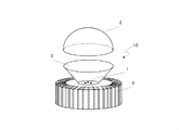
- FIG. 4 is an exploded perspective view showing an example of the light emitting device of the present invention.
- the light emitting device 10 includes an LED light source (LED element) 1 that emits blue light, and a hemispherical dome-shaped wavelength conversion member 2 disposed in front of the LED light source 1 in the light emitting direction.
- LED element LED light source
- hemispherical dome-shaped wavelength conversion member 2 disposed in front of the LED light source 1 in the light emitting direction.
- 3 is a reflector
- 4 is a radiation fin.
- the LED light source needs to include emitted light capable of exciting the phosphor in the wavelength conversion member, and includes blue light, for example, blue light having a peak wavelength of 440 to 470 nm, or light containing the blue light component. What emits is preferable.
- the LED light source 1 it is preferable to use a plurality of LED chips as an illumination LED in terms of light emission efficiency and light flux distribution.
- the wavelength conversion member needs to have a shape in which light from the LED light source enters and emits light efficiently as a light emitting device.
- This member is preferably a self-supporting member independent of the LED light source.
- the shape is not limited to the hemispherical dome shape shown in FIG. 4, but may be a curved surface shape such as an incandescent bulb, an arch shape, or a simple disk shape.
- Integral sphere light transmittance of the wavelength conversion member is preferably 20% or more and 90% or less, and more preferably 30% or more and 70% or less for blue light having a wavelength of 440 to 490 nm, particularly 440 to 470 nm. If the transmittance of the excitation light is less than 20%, the blue light emitted from the light emitting device may be insufficient, and the color balance may be deteriorated. If it exceeds 90%, the yellow light and the red light are insufficient, and the color rendering property is improved. The effect may be insufficient.
- the distance between the LED light source and the wavelength conversion member is preferably 5 mm or more.
- the wavelength conversion member may be easily deformed or deteriorated by heat from the LED light source.
- the distance between the LED light source and the wavelength conversion member may be set to an appropriate distance according to the heat generated from the LED light source.
- interval of a LED light source and a wavelength conversion member is not specifically limited, Usually, it is 5 cm or less.
- the chromaticity of the emitted light from the LED light emitting device can be adjusted by the wavelength of the emitted light, the shape and thickness of the wavelength conversion member, the phosphor content, the arrangement of the wavelength conversion member with respect to the optical axis of the LED light source, and the like.
- the content of the phosphor in the wavelength conversion member is determined in consideration of the amount of incident blue light, the amount of light emitted in the yellow wavelength region, the transmittance of blue light, etc., for example, by a wavelength conversion member having a thickness of 2 mm,
- the phosphor content is preferably 2% by mass for LuYAG phosphors, particularly 3% by mass or more and 4% by mass or less.
- the KSF phosphor is preferably 5% by mass or more, particularly 6% by mass or more, and 8% by mass or less, particularly 7% by mass or less.
- the light-emitting device of the present invention is preferably a remote phosphor type in which the LED element and the wavelength conversion member are arranged apart from each other through an air layer such as a vacuum layer or an air layer.
- 5A and 5B are schematic diagrams for explaining the light emission mode of the LED light-emitting device, in which FIG. 5A shows the light emission mode of the remote phosphor type light-emitting device, and FIG. 5B shows the light emission of the conventional multi-light white LED type light-emitting device. It is a figure which shows an aspect.
- the remote phosphor type light emitting device 10 as shown in FIG.
- a remote phosphor type light emitting device if a remote phosphor type light emitting device is adopted, a desired light emission color can be easily obtained by incorporating a wavelength conversion member that optimizes the light emission color at the final assembly stage of the light emitting device. High stability.
- the LED light source (LED chip) which is a heat generation source in the light emitting device, and the wavelength conversion member are spatially independent, heating of the wavelength conversion member is alleviated, resulting in high luminous efficiency and light emission. Equipment has a long life.
- the wavelength conversion member of the present invention is derived from red light emission having a wavelength of 600 to 660 nm, blue light emission having a wavelength of 440 to 470 nm, and LuYAG that have an effect on color rendering by arranging the LED light source such as a blue LED in the light emission direction.
- x is 0.3100 or more, especially 0.3106 in white light with good color reproducibility, especially in the chromaticity coordinates of the xy chromaticity diagram (CIE 1931).
- white light having an emission color of 0.3850 or less, particularly 0.3820 or less, y of 0.3190 or more, particularly 0.3199 or more, 0.3790 or less, particularly 0.3786 or less is obtained, This makes it possible to obtain light with good color rendering properties even in the region of a color temperature of 5000K.
- Examples 1 to 6 Transparent acrylic resin pellets Delpet (manufactured by Asahi Kasei Co., Ltd.), 0.15% by mass of lycowax E (manufactured by Clariant) as an additive was added and stirred, then heat treated at 90 ° C. for 11 hours, and simultaneously dried A wax layer was formed on the surface.
- the X-ray diffraction profile (measured with an X-ray diffractometer D8 advance (manufactured by Bruker AXS)) of the LuYAG phosphor used here is shown in FIG.
- the LuYAG phosphor used here has an emission (fluorescence) intensity of 550 nm wavelength by excitation light having a wavelength of 420 to 490 nm and an emission (fluorescence) spectrum using blue light having a wavelength of 450 nm as excitation light (both are spectroscopic).
- the photometer FP-6500 (measured by JASCO Corporation) is shown in FIGS. 2 and 3, respectively.
- acrylic resin pellets kneaded with the obtained phosphor were molded into a plate shape having a thickness of 2 mm and a 150 mm square at 250 ° C. using an injection molding machine EC130SX (manufactured by Toshiba Machine Co., Ltd.).
- the obtained resin plate was cut into a disk shape of ⁇ 60 mm to obtain a wavelength conversion member.
- the light source LED of the LED module LMH2 (manufactured by Cree) is replaced with twelve blue LEDs having a peak wavelength of 453 nm, and the flat lens is replaced with the wavelength conversion member.
- the chromaticity of light emission of this light emitting device was measured with a spectral irradiance meter CL-500A (manufactured by Konica Minolta Co., Ltd.), and the color temperature, color rendering properties and color deviation were evaluated.
- Table 1 shows the light emission characteristics of the light emitting device.
- FIG. 6 shows the emission spectrum of the light emitting device of Example 3, and
- FIG. 7 shows the coordinates on the xy chromaticity diagrams of Examples 1 to 6.
- a cerium-activated lutetium aluminum garnet phosphor represented by Lu 3 Al 5 O 12 : Ce 3+ (Ce activation rate 2 mol%), together with KSF phosphor, instead of LuYAG phosphor, Or Y 3 Al 5 O 12 : Ce 3+ (Ce activation rate 2 mol%), except that the cerium activated yttrium aluminum garnet phosphor (YAG phosphor) was used at the content shown in Table 2.
- YAG phosphor cerium activated yttrium aluminum garnet phosphor
- the X-ray diffraction profiles (measured with an X-ray diffractometer D8 advance (manufactured by Bruker AXS)) of the LuAG phosphor and the YAG phosphor used here are shown in FIG.
- the LuAG phosphor and the YAG phosphor used here have an emission (fluorescence) spectrum of 550 nm wavelength emission (fluorescence) by excitation light having a wavelength of 420 to 490 nm and an emission (fluorescence) spectrum using blue light having a wavelength of 450 nm as excitation light
- the spectrophotometer FP-6500 (measured by JASCO Corporation) is shown in FIGS. 2 and 3, respectively.
- the chromaticity of light emission of this light emitting device was measured with a spectral irradiance meter CL-500A (manufactured by Konica Minolta Co., Ltd.), and the color temperature, color rendering properties and color deviation were evaluated.
- Table 1 shows the light emission characteristics of the light emitting device.
- emission spectra of the light emitting devices of Comparative Example 3 and Comparative Example 7 are shown in FIG.
- the duv is suppressed to be small in the color temperature range of 4000 to 6700K, and Ra and R9 are smaller than those of the conventional LED light emitting device. Big light can be obtained. That is, according to the present invention, it is possible to obtain not only high contrast and color reproducibility, but also light emission with high color rendering property that gives a vivid feeling excellent in red reproducibility.
- LED light source (LED element) 1a White LED 2 Wavelength conversion member 3 Reflector 4 Radiating fin 10, 10a Light emitting device Lb Blue light Eg Yellow green light Er Red light Ey Yellow light
Landscapes
- Chemical & Material Sciences (AREA)
- Engineering & Computer Science (AREA)
- Materials Engineering (AREA)
- Organic Chemistry (AREA)
- Inorganic Chemistry (AREA)
- Luminescent Compositions (AREA)
- Led Device Packages (AREA)
- Non-Portable Lighting Devices Or Systems Thereof (AREA)
Abstract
Description
[1] 熱可塑性樹脂に蛍光体を分散させてなる波長変換部材であって、上記蛍光体が、
(A)下記組成式(1)
(Y1-α-βLuαCeβ)3Al5O12 (1)
(式中、αは0.3以上0.8以下の正数、βは0.01以上0.05以下の正数である。)
で表され、青色光で励起することにより黄緑光を発光し、かつCuのKα1線によるX線回折における回折角2θが52.9度以上53.2度以下の範囲内に回折ピークを有するセリウム賦活ルテチウムイットリウムアルミニウムガーネット蛍光体と、
(B)下記組成式(2)
K2(Si1-xMnx)F6 (2)
(式中、xは0.001以上0.3以下の正数である。)で表され、青色光で励起することにより赤色光を発光するマンガン賦活ケイ複フッ化物蛍光体とを含有し、
(B)成分の蛍光体を(A)成分の蛍光体に対して1倍以上5倍以下の質量比で含有することを特徴とする波長変換部材。
[2] 上記(A)成分の蛍光体の外観色が、CIE L*a*b*表色系における色度座標のa*値が-23.0以上-21.0以下、b*値が87.0以上97以下であることを特徴とする[1]記載の波長変換部材。
[3] 上記熱可塑性樹脂が、ポリオレフィン、ポリスチレン、スチレン共重合体、フッ素樹脂、アクリル樹脂、ナイロン、ポリエステル、ポリエチレンテレフタレート、ポリカーボネート、塩化ビニル樹脂及びポリエーテル樹脂の群から選ばれる1種又は2種以上を含むことを特徴とする[1]又は[2]記載の波長変換部材。
[4] ピーク波長440~470nmの青色光成分を含む光を出射する青色LED光源と、該青色LED光源の光軸上に配置された[1]乃至[3]のいずれかに記載の波長変換部材とを備えることを特徴とする発光装置。
[5] 発光色が、xy色度図(CIE 1931)の色度座標において、xが0.3100以上0.3850以下、yが0.3190以上0.3790以下であることを特徴とする[4]記載の発光装置。
[6] リモートフォスファー型であることを特徴とする[4]又は[5]記載の発光装置。
まず、本発明の波長変換部材について説明する。
本発明の波長変換部材には、熱可塑性樹脂と蛍光体とが含まれ、波長変換部材は、熱可塑性樹脂に蛍光体を分散させた樹脂成形体である。蛍光体は、粒子状又は粉状のものが好適に用いられる。
(Y1-α-βLuαCeβ)3Al5O12 (1)
(式中、αは0.3以上0.8以下の正数、βは0.01以上0.05以下の正数である。)
で表され、青色光で励起することにより黄緑光を発光する蛍光体であり、構成元素のLu、Y又はそれら双方のサイトの一部が3価のセリウム(Ce3+)に置換された構造を有している。そのため、LuYAG蛍光体は、(Y,Lu)3Al5O12:Ce又は(Y,Lu)3Al5O12:Ce3+と表記される場合もある。LuYAG蛍光体は、波長420~490nm、好ましくは波長440~470nmの青色光により励起されて、主波長が563~570nmのブロードな発光スペクトルを有する黄緑光を発光する。
K2(Si1-xMnx)F6 (2)
(式中、xは0.001以上で、0.3以下、好ましくは0.1以下の正数である。)で表され、青色光で励起することにより赤色光を発光する蛍光体であり、構成元素のうちSiのサイトの一部が4価のマンガン(Mn4+)に置換された構造を有している。そのため、KSF蛍光体は、K2SiF6:Mn又はK2SiF6:Mn4+と表記される場合もある。KSF蛍光体は、波長420~490nm、好ましくは波長440~470nmの青色光により励起されて、波長630~640nmの範囲内に最大の発光ピークを有する赤色光を発光する。
本発明の発光装置は、ピーク波長440~470nmの青色光成分を含む光を出射する青色LED光源と、青色LED光源の光軸上に配置された波長変換部材とを備える。この青色LED光源としては、青色LEDを用いても、青色LEDを用いた疑似白色LED、即ち、青色成分を含む光を発光する疑似白色LEDを用いてもよい。
透明アクリル樹脂ペレット デルペット(旭化成(株)製)に、添加剤としてリコワックスE(クラリアント社製)を0.15質量%加えて撹拌した後、90℃で11時間熱処理し、乾燥と同時にペレット表面にワックス層を形成した。この添加剤混合アクリル樹脂ペレット8kgに、二軸押出機(東芝機械(株)製)を用い、粒径D50が約15μmのK2(Si0.98Mn0.02)F6で表わされるKSF蛍光体と共に、粒径D50が約12μm、外観色が、CIE L*a*b*表色系における明度L*の値が106.30、色度座標のa*値が-22.28、b*値が93.25である(Y0.294Lu0.686Ce0.02)3Al5O12で表わされるLuYAG蛍光体を、表1に示される含有率で、230℃で混練して、蛍光体を練り込んだアクリル樹脂ペレットを得た。

蛍光体として、KSF蛍光体と共に、LuYAG蛍光体の代わりに、Lu3Al5O12:Ce3+(Ce賦活率2mol%)で表されるセリウム賦活ルテチウムアルミニウムガーネット蛍光体(LuAG蛍光体)、又はY3Al5O12:Ce3+(Ce賦活率2mol%)で表されるセリウム賦活イットリウムアルミニウムガーネット蛍光体(YAG蛍光体)を、表2に示される含有率で用いた以外は、実施例と同様にして、波長変換部材を得、得られた波長変換部材を用いてリモートフォスファー型発光装置を作製した。

1a 白色LED
2 波長変換部材
3 リフレクター
4 放熱フィン
10,10a 発光装置
Lb 青色光
Eg 黄緑光
Er 赤色光
Ey 黄色光
Claims (6)
- 熱可塑性樹脂に蛍光体を分散させてなる波長変換部材であって、上記蛍光体が、
(A)下記組成式(1)
(Y1-α-βLuαCeβ)3Al5O12 (1)
(式中、αは0.3以上0.8以下の正数、βは0.01以上0.05以下の正数である。)
で表され、青色光で励起することにより黄緑光を発光し、かつCuのKα1線によるX線回折における回折角2θが52.9度以上53.2度以下の範囲内に回折ピークを有するセリウム賦活ルテチウムイットリウムアルミニウムガーネット蛍光体と、
(B)下記組成式(2)
K2(Si1-xMnx)F6 (2)
(式中、xは0.001以上0.3以下の正数である。)で表され、青色光で励起することにより赤色光を発光するマンガン賦活ケイ複フッ化物蛍光体とを含有し、
(B)成分の蛍光体を(A)成分の蛍光体に対して1倍以上5倍以下の質量比で含有することを特徴とする波長変換部材。 - 上記(A)成分の蛍光体の外観色が、CIE L*a*b*表色系における色度座標のa*値が-23.0以上-21.0以下、b*値が87.0以上97以下であることを特徴とする請求項1記載の波長変換部材。
- 上記熱可塑性樹脂が、ポリオレフィン、ポリスチレン、スチレン共重合体、フッ素樹脂、アクリル樹脂、ナイロン、ポリエステル、ポリエチレンテレフタレート、ポリカーボネート、塩化ビニル樹脂及びポリエーテル樹脂の群から選ばれる1種又は2種以上を含むことを特徴とする請求項1又は2記載の波長変換部材。
- ピーク波長440~470nmの青色光成分を含む光を出射する青色LED光源と、該青色LED光源の光軸上に配置された請求項1乃至3のいずれか1項記載の波長変換部材とを備えることを特徴とする発光装置。
- 発光色が、xy色度図(CIE 1931)の色度座標において、xが0.3100以上0.3850以下、yが0.3190以上0.3790以下であることを特徴とする請求項4記載の発光装置。
- リモートフォスファー型であることを特徴とする請求項4又は5記載の発光装置。
Priority Applications (2)
| Application Number | Priority Date | Filing Date | Title |
|---|---|---|---|
| US15/534,365 US10450505B2 (en) | 2014-12-09 | 2015-11-27 | Wavelength conversion member and light-emitting device |
| JP2016563611A JP6376225B2 (ja) | 2014-12-09 | 2015-11-27 | 波長変換部材及び発光装置 |
Applications Claiming Priority (2)
| Application Number | Priority Date | Filing Date | Title |
|---|---|---|---|
| JP2014-248972 | 2014-12-09 | ||
| JP2014248972 | 2014-12-09 |
Publications (1)
| Publication Number | Publication Date |
|---|---|
| WO2016093076A1 true WO2016093076A1 (ja) | 2016-06-16 |
Family
ID=56107266
Family Applications (1)
| Application Number | Title | Priority Date | Filing Date |
|---|---|---|---|
| PCT/JP2015/083313 Ceased WO2016093076A1 (ja) | 2014-12-09 | 2015-11-27 | 波長変換部材及び発光装置 |
Country Status (4)
| Country | Link |
|---|---|
| US (1) | US10450505B2 (ja) |
| JP (1) | JP6376225B2 (ja) |
| TW (1) | TWI679780B (ja) |
| WO (1) | WO2016093076A1 (ja) |
Cited By (7)
| Publication number | Priority date | Publication date | Assignee | Title |
|---|---|---|---|---|
| JP2018129450A (ja) * | 2017-02-10 | 2018-08-16 | 信越化学工業株式会社 | 白色光源及びled照明装置 |
| CN108630795A (zh) * | 2017-03-17 | 2018-10-09 | 日亚化学工业株式会社 | 透光性构件的制造方法以及发光装置的制造方法 |
| CN113024253A (zh) * | 2019-12-09 | 2021-06-25 | 上海航空电器有限公司 | 用于激光照明的高显色性包边复合结构波长转换陶瓷及其制备方法 |
| WO2021132330A1 (ja) * | 2019-12-26 | 2021-07-01 | 住友化学株式会社 | 表示装置 |
| US20220153631A1 (en) * | 2019-03-08 | 2022-05-19 | Nippon Electric Glass Co., Ltd. | Wavelength-conversion member and light-emitting device |
| CN116096836A (zh) * | 2021-07-27 | 2023-05-09 | 昕诺飞控股有限公司 | 白光发射装置 |
| CN118630117A (zh) * | 2024-06-03 | 2024-09-10 | 东莞市立德达光电科技有限公司 | 教育照明光谱led光源及其制备方法 |
Families Citing this family (13)
| Publication number | Priority date | Publication date | Assignee | Title |
|---|---|---|---|---|
| DE102014112681A1 (de) * | 2014-09-03 | 2016-03-03 | Osram Opto Semiconductors Gmbh | Optoelektronisches Halbleiterbauteil und Blitzlicht |
| DE102015106995A1 (de) * | 2015-05-05 | 2016-11-10 | Osram Opto Semiconductors Gmbh | Optischer Herzfrequenzsensor |
| DE102018101428A1 (de) | 2018-01-23 | 2019-07-25 | Osram Opto Semiconductors Gmbh | Optoelektronisches Bauelement |
| US10916530B2 (en) * | 2018-04-19 | 2021-02-09 | Innolux Corporation | Electronic device |
| CH715231A1 (de) * | 2018-08-06 | 2020-02-14 | Alpla Werke Alwin Lehner Gmbh & Co Kg | Verfahren zur Aufbereitung von zur Wiederverwendung vorgesehenen Thermoplasten. |
| CN114026201B (zh) * | 2019-06-28 | 2023-10-20 | 电化株式会社 | 荧光体板和使用该荧光体板的发光装置 |
| EP4136187A4 (en) | 2020-04-14 | 2024-06-19 | General Electric Company | GREEN-EMMITTING PHOSPHORS AND DEVICES THEREFOR |
| WO2021211181A1 (en) | 2020-04-14 | 2021-10-21 | General Electric Company | Ink compositions and films with narrow band emission phosphor materials |
| CN116348571B (zh) | 2020-09-01 | 2024-11-29 | 通用电气公司 | 与夜视设备兼容的装置 |
| WO2023107737A1 (en) * | 2021-12-10 | 2023-06-15 | EcoSense Lighting, Inc. | Low-blue light source |
| TW202438643A (zh) * | 2023-03-20 | 2024-10-01 | 美商奇異電器公司 | 用於沉積含磷光體之墨水的系統及方法 |
| WO2025021540A1 (en) * | 2023-07-25 | 2025-01-30 | Signify Holding B.V. | Led device comprising yag phosphor particles and red luminescent particles |
| WO2025257240A1 (en) * | 2024-06-13 | 2025-12-18 | Signify Holding B.V. | A light generating system |
Citations (3)
| Publication number | Priority date | Publication date | Assignee | Title |
|---|---|---|---|---|
| JP2013102078A (ja) * | 2011-11-09 | 2013-05-23 | Stanley Electric Co Ltd | 光源装置および照明装置 |
| WO2013121355A1 (en) * | 2012-02-16 | 2013-08-22 | Koninklijke Philips N.V. | Coated narrow band red-emitting fluorosilicates for semiconductor leds |
| JP2013171844A (ja) * | 2012-02-17 | 2013-09-02 | Stanley Electric Co Ltd | 光源装置および照明装置 |
Family Cites Families (5)
| Publication number | Priority date | Publication date | Assignee | Title |
|---|---|---|---|---|
| MY167700A (en) | 2011-04-08 | 2018-09-21 | Shinetsu Chemical Co | Preparation of complex fluoride and complex fluoride phosphor |
| JP6069890B2 (ja) * | 2012-05-29 | 2017-02-01 | 日亜化学工業株式会社 | 波長変換用無機成形体及び発光装置 |
| RU2639733C2 (ru) * | 2012-11-01 | 2017-12-22 | Люмиледс Холдинг Б.В. | Устройство с широкой цветовой палитрой на основе сид |
| JP6186851B2 (ja) * | 2013-04-26 | 2017-08-30 | 日亜化学工業株式会社 | バックライト光源ユニット及びその製造方法並びに液晶表示装置 |
| JP6036728B2 (ja) * | 2014-02-28 | 2016-11-30 | 信越化学工業株式会社 | 照明装置 |
-
2015
- 2015-11-27 JP JP2016563611A patent/JP6376225B2/ja not_active Expired - Fee Related
- 2015-11-27 US US15/534,365 patent/US10450505B2/en not_active Expired - Fee Related
- 2015-11-27 WO PCT/JP2015/083313 patent/WO2016093076A1/ja not_active Ceased
- 2015-12-09 TW TW104141290A patent/TWI679780B/zh not_active IP Right Cessation
Patent Citations (3)
| Publication number | Priority date | Publication date | Assignee | Title |
|---|---|---|---|---|
| JP2013102078A (ja) * | 2011-11-09 | 2013-05-23 | Stanley Electric Co Ltd | 光源装置および照明装置 |
| WO2013121355A1 (en) * | 2012-02-16 | 2013-08-22 | Koninklijke Philips N.V. | Coated narrow band red-emitting fluorosilicates for semiconductor leds |
| JP2013171844A (ja) * | 2012-02-17 | 2013-09-02 | Stanley Electric Co Ltd | 光源装置および照明装置 |
Cited By (12)
| Publication number | Priority date | Publication date | Assignee | Title |
|---|---|---|---|---|
| JP2018129450A (ja) * | 2017-02-10 | 2018-08-16 | 信越化学工業株式会社 | 白色光源及びled照明装置 |
| CN108630795A (zh) * | 2017-03-17 | 2018-10-09 | 日亚化学工业株式会社 | 透光性构件的制造方法以及发光装置的制造方法 |
| CN108630795B (zh) * | 2017-03-17 | 2023-01-13 | 日亚化学工业株式会社 | 透光性构件的制造方法以及发光装置的制造方法 |
| US20220153631A1 (en) * | 2019-03-08 | 2022-05-19 | Nippon Electric Glass Co., Ltd. | Wavelength-conversion member and light-emitting device |
| CN113024253A (zh) * | 2019-12-09 | 2021-06-25 | 上海航空电器有限公司 | 用于激光照明的高显色性包边复合结构波长转换陶瓷及其制备方法 |
| CN113024253B (zh) * | 2019-12-09 | 2023-09-12 | 上海航空电器有限公司 | 用于激光照明的高显色性包边复合结构波长转换陶瓷及其制备方法 |
| WO2021132330A1 (ja) * | 2019-12-26 | 2021-07-01 | 住友化学株式会社 | 表示装置 |
| JP2021105712A (ja) * | 2019-12-26 | 2021-07-26 | 住友化学株式会社 | 表示装置 |
| CN114902088A (zh) * | 2019-12-26 | 2022-08-12 | 住友化学株式会社 | 显示装置 |
| JP7701147B2 (ja) | 2019-12-26 | 2025-07-01 | 住友化学株式会社 | 表示装置 |
| CN116096836A (zh) * | 2021-07-27 | 2023-05-09 | 昕诺飞控股有限公司 | 白光发射装置 |
| CN118630117A (zh) * | 2024-06-03 | 2024-09-10 | 东莞市立德达光电科技有限公司 | 教育照明光谱led光源及其制备方法 |
Also Published As
| Publication number | Publication date |
|---|---|
| TWI679780B (zh) | 2019-12-11 |
| US10450505B2 (en) | 2019-10-22 |
| TW201633568A (zh) | 2016-09-16 |
| JPWO2016093076A1 (ja) | 2017-09-14 |
| JP6376225B2 (ja) | 2018-08-22 |
| US20170342320A1 (en) | 2017-11-30 |
Similar Documents
| Publication | Publication Date | Title |
|---|---|---|
| JP6376225B2 (ja) | 波長変換部材及び発光装置 | |
| JP6079927B2 (ja) | 波長変換部材及び発光装置の作製方法 | |
| EP2940742A1 (en) | Light emitting device | |
| JP6197908B2 (ja) | 発光装置 | |
| WO2011142127A1 (ja) | Ledモジュール、ledランプおよび照明装置 | |
| JP5920488B2 (ja) | 蛍光体含有樹脂成型体、発光装置、蛍光体含有樹脂成型体用樹脂ペレット、並びに蛍光体含有樹脂成型体及び蛍光体含有樹脂成型体用樹脂ペレットの製造方法 | |
| CN102959312A (zh) | Led灯泡 | |
| CN107461717A (zh) | 一种光源模组及包括该光源模组的照明装置 | |
| JP6098747B2 (ja) | 調整部品及び発光装置 | |
| JP2018129450A (ja) | 白色光源及びled照明装置 |
Legal Events
| Date | Code | Title | Description |
|---|---|---|---|
| 121 | Ep: the epo has been informed by wipo that ep was designated in this application |
Ref document number: 15868512 Country of ref document: EP Kind code of ref document: A1 |
|
| ENP | Entry into the national phase |
Ref document number: 2016563611 Country of ref document: JP Kind code of ref document: A |
|
| WWE | Wipo information: entry into national phase |
Ref document number: 15534365 Country of ref document: US |
|
| NENP | Non-entry into the national phase |
Ref country code: DE |
|
| 122 | Ep: pct application non-entry in european phase |
Ref document number: 15868512 Country of ref document: EP Kind code of ref document: A1 |