WO2016092871A1 - 電動機の診断装置 - Google Patents
電動機の診断装置 Download PDFInfo
- Publication number
- WO2016092871A1 WO2016092871A1 PCT/JP2015/060055 JP2015060055W WO2016092871A1 WO 2016092871 A1 WO2016092871 A1 WO 2016092871A1 JP 2015060055 W JP2015060055 W JP 2015060055W WO 2016092871 A1 WO2016092871 A1 WO 2016092871A1
- Authority
- WO
- WIPO (PCT)
- Prior art keywords
- phase current
- motor
- current
- voltage
- circuit
- Prior art date
Links
Images


Classifications
-
- G—PHYSICS
- G01—MEASURING; TESTING
- G01R—MEASURING ELECTRIC VARIABLES; MEASURING MAGNETIC VARIABLES
- G01R31/00—Arrangements for testing electric properties; Arrangements for locating electric faults; Arrangements for electrical testing characterised by what is being tested not provided for elsewhere
- G01R31/34—Testing dynamo-electric machines
- G01R31/343—Testing dynamo-electric machines in operation
-
- G—PHYSICS
- G01—MEASURING; TESTING
- G01R—MEASURING ELECTRIC VARIABLES; MEASURING MAGNETIC VARIABLES
- G01R31/00—Arrangements for testing electric properties; Arrangements for locating electric faults; Arrangements for electrical testing characterised by what is being tested not provided for elsewhere
- G01R31/34—Testing dynamo-electric machines
- G01R31/346—Testing of armature or field windings
-
- G—PHYSICS
- G01—MEASURING; TESTING
- G01R—MEASURING ELECTRIC VARIABLES; MEASURING MAGNETIC VARIABLES
- G01R29/00—Arrangements for measuring or indicating electric quantities not covered by groups G01R19/00 - G01R27/00
- G01R29/16—Measuring asymmetry of polyphase networks
-
- H—ELECTRICITY
- H02—GENERATION; CONVERSION OR DISTRIBUTION OF ELECTRIC POWER
- H02P—CONTROL OR REGULATION OF ELECTRIC MOTORS, ELECTRIC GENERATORS OR DYNAMO-ELECTRIC CONVERTERS; CONTROLLING TRANSFORMERS, REACTORS OR CHOKE COILS
- H02P23/00—Arrangements or methods for the control of AC motors characterised by a control method other than vector control
Definitions
- the present invention relates to a motor diagnostic apparatus that monitors the state of a motor and protects the motor against an abnormal state.
- constant motor monitoring is based on the premise that measuring devices such as various sensors are attached to each motor. Examples of the measuring device include a torque meter, an encoder, and an acceleration sensor.
- the measuring device include a torque meter, an encoder, and an acceleration sensor.
- application to a motor control center that centrally manages hundreds to thousands of motors increases the number of wirings, so that application is not practical. Therefore, there is a need for a device that simply diagnoses the state of the motor from the current and voltage information measured at the motor control center without using a special sensor, and improves reliability, productivity, and safety.
- the steady-state current setting circuit adjusts the current during steady-state operation, and using this as a reference, the upper and lower limits of the allowable fluctuation range and the pulsation signal value are set.
- the load current of the motor is constantly monitored to monitor the abnormal operation state of the motor (see Patent Document 1).
- a feature amount detecting means for detecting a feature amount from a current flowing through the motor to be diagnosed, and an average and standard deviation of the feature amount obtained by the feature amount detecting means when the motor is in a normal state are derived and stored.
- a detection unit that detects a voltage supplied from a power source to the motor to be diagnosed and a current flowing through the stator winding of the motor, and a time when the voltage detected by the detection unit becomes zero is a start time.
- the stator A motor stator winding short-circuit diagnosis system includes a determination unit that determines that the winding is short-circuited (see Patent Document 3).
- JP-A-62-218883 JP 2012-220485 A Japanese Patent No. 4367784
- the present invention has been made to solve the above-described problems, and is not affected by load torque fluctuation, power supply imbalance, and poor contact failure from voltage and current information obtained online while the motor is operating.
- the present invention provides a motor diagnostic apparatus for the purpose of detecting only a short-circuit fault in a stator winding of an electric motor.
- a motor diagnosis apparatus includes a current detection circuit that detects a current of a motor from a current flowing in a main circuit of a power supply connected to the motor, and a voltage detection circuit that detects a voltage of the motor from a voltage of the main circuit of the power supply And a logic operation unit that inputs the output of the current detection circuit and the voltage detection circuit to determine the winding short-circuit abnormality of the motor, and a display that displays an abnormality when the logic operation unit detects an abnormality of the motor And an external output unit that informs the outside that the abnormality has occurred when the logic operation unit detects an abnormality in the motor.
- the logic operation unit has a negative phase current, a negative phase voltage, a positive phase voltage based on the motor voltage and current analysis. From the phase current and the negative phase admittance, even when the load torque fluctuates while the motor is operating, the power supply imbalance is distinguished and the winding short-circuit is determined and detected.
- the motor diagnosis device includes a current detection circuit that detects a current of a motor from a current flowing in a main circuit of a power source connected to the motor, and an output of the current detection circuit, and the winding of the motor
- a logic operation unit for determining a short circuit abnormality a display unit for displaying an abnormality when the logic operation unit detects an abnormality in the motor, and an abnormality when the logic operation unit detects an abnormality in the motor.
- An external output unit that informs the outside, and the logical operation unit distinguishes power supply imbalances even when the load torque fluctuates while the motor is operating, from the negative phase current and the positive phase current based on the motor voltage and current analysis.
- a short circuit is determined and detected.
- the present invention by calculating the negative phase admittance characteristic, the negative phase current-positive phase current characteristic, and the voltage imbalance rate, in the electric motor with the load torque fluctuation during operation, the winding short-circuit and the voltage imbalance simultaneously Even in this case, it is possible to detect only a winding short circuit without erroneous detection. There is an unprecedented remarkable effect that false detection is not performed in both power supply unbalance and power line contact failure which are causes of voltage unbalance.
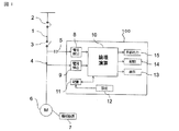
- FIG. 1 is a structural circuit diagram showing an electric motor diagnosis apparatus according to Embodiment 1 of the present invention, which is mainly used in a control center which is a closed switchboard.
- the main circuit 1 of the power source drawn from the power system includes the circuit breaker 2, the magnetic contactor 3, the instrument transformer 4 that detects the load current of the main circuit 1, and the voltage of the main circuit 1.
- An instrument transformer 5 for detection is provided, and an electric motor 6 as a load is further connected, and the mechanical equipment 7 is driven by the electric motor 6.
- An electric motor diagnosis apparatus 100 includes a voltage detection circuit 8 connected to an instrument transformer 5, a current detection circuit 9 connected to an instrument transformer 4, a logic operation circuit (logic operation unit) 10, and a storage circuit 11 and a setting circuit 12.
- the voltage detection circuit 8 detects the line voltage of the main circuit 1 of the power source connected to the electric motor, converts it into a predetermined signal such as the phase voltage and magnitude of the electric motor, detects the voltage of the electric motor, and the logical operation circuit 10 and the memory circuit 11.
- the current detection circuit 9 detects the load current of the main circuit 1 of the power supply connected to the electric motor, converts it into a predetermined signal such as the phase current and magnitude of the electric motor, detects the electric current of the electric motor, and the logical operation circuit 10 And output to the memory circuit 11.
- the logical operation circuit 10 inputs the outputs of the voltage detection circuit 8 and the current detection circuit 9, and calculates a negative phase current, a negative phase voltage, a positive phase current, a negative phase admittance, etc. by analyzing the voltage and current of the motor. Even when the load torque fluctuates while the motor is in operation, the winding short circuit is determined and detected by distinguishing power imbalance and poor contact.
- the setting circuit 12 is connected to the storage circuit 11 and has a set key. When the set key is pressed (for example, long press), the data in the initial normal state is stored and held in the storage circuit 11. Data until the set key is released can be stored.
- the display circuit (display unit) 13 is connected to the logical operation circuit 10 and displays an abnormal state, a warning or the like when the load current or the logical operation circuit 10 detects an abnormality of the electric motor 6.
- the drive circuit 14 is connected to the logic operation circuit 10, and opens and closes the electromagnetic contactor 3 by an output by calculation of a current detection signal from the instrument transformer 4.
- the external output circuit (external output unit) 15 outputs an abnormal state or warning from the logical operation circuit 10 to the outside.
- Fig. 2 shows an image of winding short-circuit failure diagnosed this time.
- the stator winding of the electric motor 6 may cause both the same-layer short circuit and the interlayer short circuit.
- Nf the number of short-circuited turns
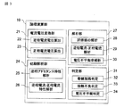
- FIG. 3 shows an internal configuration diagram of a logical operation circuit 10 that performs short-circuit detection determination of the stator winding of the electric motor 6.
- the logical operation circuit 10 includes a current-voltage conversion unit 21, an initial analysis unit 24, an analysis unit 27, and a determination unit. 31 is comprised.
- the current-voltage converter 21 includes a negative-phase current / negative-phase voltage calculator 22 and a positive-phase current / positive-phase voltage calculator 23, and the three-phase voltage and current detected by the voltage detector 8 and the current detector 9. Are converted into the negative-phase current Isn, the negative-phase voltage Vsn, the positive-phase current Isp, and the positive-phase voltage Vsp by the calculation formulas (1) to (4) by the symmetrical coordinate conversion process.
- Isp positive phase current
- Isn reverse phase current
- Iu U phase current
- Iv V phase current
- Iw W phase current
- Vsp positive phase voltage
- Vsn reverse phase voltage
- Vu U phase voltage
- Vv V-phase voltage
- Vw W-phase voltage
- the positive phase voltage and the reverse phase voltage may be obtained from the line voltage in addition to the method obtained from the phase voltage.
- the initial analysis unit 24 includes a normal phase anti-phase admittance characteristic analysis unit 25 and an anti-phase current-normal phase current characteristic analysis unit 26.
- the negative phase admittance characteristic analysis unit 25 stores the normal phase negative admittance value Yn before determining a winding short circuit.
- the negative phase admittance Yn varies depending on the slip. That is, the value varies depending on the magnitude of the load torque.
- the reverse admittance characteristic with respect to the normal phase current value at the normal time is stored.
- the timing for storing is preferably when the motor is in operation. This is because reverse phase admittance data from no load to load can be acquired.
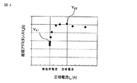
- FIG. 4 is a graph of the characteristics of the negative phase admittance Yn due to the change of the positive phase current Isp.
- the negative phase admittance value Y41 at the time of no load current is small, and the negative phase admittance value Y42 at the time of load is large.
- the amount of data to be stored is small. Therefore, in reverse-phase admittance at a location where data cannot be acquired, for example, the value is determined by complementing with approximate curve processing.
- the negative phase admittance Yn varies depending on the load torque fluctuation, and it is necessary to store at least a negative phase admittance value within a torque range assumed during normal operation.
- the negative-phase current-positive-phase current characteristic analysis unit 26 is implemented to make a contact failure determination.
- the poor contact is assumed to be, for example, a screw tightening portion for connecting the electric motor 6 and the power cable (main circuit 1), other screw locations, or cable deterioration.
- a threshold value is determined from a statistical process such as a least square method based on the normal amount data and an increase amount of the negative phase current Isn with respect to the positive phase current Isp used as an evaluation of the winding short circuit determination. At this time, the increase cannot be calculated unless the positive phase current Isp changes. Usually, it is considered that there is no problem because the load equipment is always in a state where torque is generated.
- the winding short-circuit determination method changes depending on the increase value of the negative-phase current Isn with respect to the positive-phase current Isp. If a resistance component exists due to poor contact, the increase value of the reverse phase current Isn with respect to the positive phase current Isp increases.
- FIG. 5 is a graph of the characteristics of the positive phase current Isp and the negative phase current Isn.
- the increase amount of the reverse phase current Isn with respect to the positive phase current Isp is small, and the inclination thereof is small.
- the characteristic I52 and the characteristic I53 when there is a contact resistance increase the amount of increase of the reverse phase current Isn with respect to the positive phase current Isp, and the inclination thereof increases.
- the characteristic I53 is larger than the characteristic I52.
- a threshold value ⁇ 2 for determining contact failure is determined in advance based on a normal result (for example, characteristic I51).
- the analysis unit 27 includes an evaluation value analysis unit 28, a negative phase current-normal phase current analysis unit 29, and a voltage imbalance rate analysis unit 30, and a winding short-circuit determination unit 32, a contact failure determined by the determination unit 31. Analysis for the determination unit 33 and the voltage imbalance determination unit 34 is performed.
- the current (Iu, Iv, Iw) voltage (Vuv, Vvw, Vwu) is updated from the voltage detection circuit 8 and the current detection circuit 9. Winding short-circuiting is a short-circuiting phenomenon between coil strands.
- Yp, Yn, Ypn Admittance
- ⁇ Power supply angular velocity
- rs Stator resistance
- rr Rotor resistance
- rf Short-circuit resistance
- Ls Stator leakage inductance
- Lr Rotor leakage inductance
- Lm Excitation Inductance
- ⁇ Short-circuit rate.
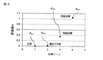
- FIG. 6 is a diagram showing the relationship of the evaluation value A for each failure case.
- the evaluation value A61 at the normal time and the evaluation value A62 at the time of voltage imbalance are small, and the evaluation values A63 and A64 when a short circuit fault occurs are large. Therefore, by setting the threshold value ⁇ 1 of the evaluation value A between the evaluation value A62 and the evaluation value A63, it becomes possible to detect a winding short-circuit fault as distinguished from voltage imbalance.
- the negative phase admittance Yn uses data calculated by the negative phase admittance characteristic analysis unit 25. Then, the evaluation value can be analyzed by substituting the negative phase admittance value in each positive phase current at the time of the evaluation value analysis by the evaluation value analysis unit 28.
- the negative phase current-positive phase current analysis unit 29 analyzes the increase amount of the negative phase current Isn with respect to the positive phase current Isp. Before carrying out the determination, the increase amount of the normal phase negative current-normal phase current characteristic analyzed by the negative phase current-normal phase current characteristic analysis unit 26 is stored, and the threshold value ⁇ 2 is determined by statistical processing. Keep it. Then, the negative-phase current-positive-phase current analysis unit 29 analyzes the increase amount of the negative-phase current Isn with respect to the positive-phase current Isp, and determines the winding of the motor 6 depending on whether the increase amount is larger or smaller than the threshold value ⁇ 2. Make it possible to distinguish between short circuits and poor contacts.
- the voltage imbalance ratio analysis unit 30 calculates the voltage imbalance ratio from the phase voltage of each phase or the line voltage.
- the voltage imbalance rate Vunbal is obtained by the following equation when calculated from the line voltage, for example.
- each analysis result calculated by the analysis unit 27 is compared with the threshold values ⁇ 1, ⁇ 2, etc., so that the winding short circuit determination unit 32 determines the winding short circuit, and the contact failure determination unit 33 performs the contact.
- a failure is determined, and the voltage imbalance determination unit 34 determines the voltage imbalance.
- the determination result is sent to the display circuit 13, the drive circuit 14, and the external output circuit 15 shown in FIG.
- the display circuit 13 displays an abnormal state, a warning or the like when detecting an abnormality such as a winding short circuit or a contact failure of the electric motor 6.
- the drive circuit 14 opens and closes the electromagnetic contactor 3 when detecting an abnormality of the electric motor 6.
- the external output circuit (external output unit) 15 outputs an abnormal state, a warning, or the like of the motor 6 described above.
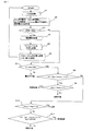
- step S1 the voltage (line voltage or phase voltage) V and current (phase current) I of the motor are acquired.
- step S2 the negative phase current Isn, the negative phase voltage Vsn, the positive phase current Isp, and the voltage unbalance rate Vunbal.
- the power supply voltage Vs is calculated.
- step S3 an initial determination is made, and when it is the first time (Yes), the process proceeds to step S4 to store the power supply voltage Vs. Note that the calculation of the power supply voltage Vs in step S2 and the storage of the power supply voltage Vs in step S4 may be omitted.
- step S5 the negative phase admittance Yn is calculated from the negative phase current-negative phase voltage characteristic, and the positive phase current characteristic of the negative phase admittance Yn is stored.
- step S6 an increase amount ⁇ In / ⁇ Isp of the reverse phase current Isn with respect to the positive phase current Isp is calculated from the reverse phase current-positive phase current characteristics, and an increase amount threshold ⁇ 2 is set. Then return to START.
- step S3 if it is not the first time (No), the process proceeds to step S7, and the voltage unbalance rate Vunbal is compared with a threshold value of 5%.
- This threshold value 5% is not limited to this value, and can be set to a predetermined value at which voltage imbalance appears to have occurred.
- step S7 when the voltage unbalance rate Vunbal is equal to or greater than the threshold value 5% (No), voltage unbalance is displayed.
- the evaluation value A
- step S9 When the evaluation value A is equal to or greater than the threshold value ⁇ 1 (Yes), the process proceeds to step S9, and the increase amount ⁇ In / ⁇ Isp of the reverse phase current Isn with respect to the positive phase current Isp is compared with the threshold value ⁇ 2.
- step S9 when the negative phase current ⁇ Isn / positive phase current ⁇ Isp is less than the threshold value ⁇ 2 (Yes), it is determined that the winding is short-circuited, and the negative phase current ⁇ In / positive phase current ⁇ Isp is the threshold value ⁇ 2. When it is above (No), it determines with a contact failure.
- step S10 If the evaluation value A is less than the threshold value ⁇ 1 in step S8 (No), the process proceeds to step S10, and the increase amount ⁇ In / ⁇ Isp of the reverse phase current Isn with respect to the positive phase current Isp is compared with the threshold value ⁇ 2. To do.
- step S10 when the increase amount of the reverse phase current Isn with respect to the positive phase current Isp is less than the threshold value ⁇ 2 (Yes), it is determined as normal.
- the increase amount ⁇ Isn / ⁇ Isp of the negative phase current Isn with respect to the positive phase current Isp is equal to or greater than the threshold value ⁇ 2 (No) the process proceeds to step S11.
- step S11 the characteristic of the evaluation value A with respect to the positive phase current Isp is calculated, an intercept is obtained by approximating the positive phase current Isp to 0 A (intercept is obtained by a least square method from a plurality of measurement plots), and the value is obtained. Compare with threshold value ⁇ 3. This threshold value ⁇ 3 is slightly smaller than the threshold value ⁇ 1. In step S11, when the evaluation value A is equal to or greater than the threshold value ⁇ 3 (Yes), it is determined that the winding is short-circuited, and when it is less than the threshold value ⁇ 3 (No), it is determined that the contact is poor.
- the invention of the first embodiment determines the abnormal state of the motor by the elements of the negative phase current, the negative phase voltage, the positive phase current, and the negative phase admittance based on the analysis of the voltage and current of the motor. Even when the load torque fluctuates during operation of the electric motor, it is possible to detect and detect the winding short circuit by distinguishing the power imbalance. Further, it is possible to determine a winding short circuit of the electric motor even when the contact of the power supply line is poor.
- FIG. 8 shows a flowchart of the diagnostic process in the second embodiment. Steps S1 to S7 are the same as those in the first embodiment, and a description thereof will be omitted.
- step S8 compares the increase amount of the reverse phase current Isn with respect to the positive phase current Isp with a threshold value ⁇ 2. In step S8, when the increase amount of the reverse phase current Isn with respect to the positive phase current Isp is less than the threshold value ⁇ 2 (Yes), the process proceeds to step S9.
- the evaluation value A is greater than or equal to the threshold value ⁇ 1 (Yes)
- the evaluation value A is less than the threshold value ⁇ 1 (No)
- step S8 when the increase amount of the reverse phase current Isn with respect to the positive phase current Isp is equal to or greater than the threshold value ⁇ 2 (No), the process proceeds to step S10.
- step S10 the characteristic of the evaluation value A with respect to the positive phase current Isp is calculated, an intercept is obtained by approximating the positive phase current Isp to 0A (intercept is obtained by a least square method from a plurality of measurement plots), and the value is obtained. Compare with threshold value ⁇ 3. If the value is equal to or greater than the threshold value ⁇ 3 (Yes), it is determined that the winding is short-circuited, and if it is less than the threshold value ⁇ 3 (No), it is determined that the contact is poor.
- the invention of the second embodiment is similar to the first embodiment in that the abnormality of the motor is caused by the elements of the negative phase current, the negative phase voltage, the positive phase current, and the negative phase admittance by analyzing the voltage and current of the motor.
- the state is determined, even if the determination method is changed to that of the first embodiment, the winding short-circuit can be determined and detected even when the load torque varies while the motor is operating. Further, it is possible to determine a winding short circuit of the electric motor even when the contact of the power supply line is poor.
- Embodiment 3 a motor diagnostic apparatus according to Embodiment 3 of the present invention will be described.
- one logical operation unit 10 is provided for each electric motor 6, but in the third embodiment, a plurality of electric motors are analyzed for voltage and current signals by one logical operation unit 10. The abnormality is determined.
- the abnormal value is stored for the first time.
- by collectively processing the information of a plurality of motors for example, in the case of the same motor, it is possible to determine whether it is normal or abnormal in the first determination.
- FIG. 9 is a structural circuit diagram showing a motor diagnostic apparatus according to Embodiment 4 of the present invention, in which the instrument transformer 5 and the voltage detection circuit 8 are removed from the configuration of FIG.
- the same reference numerals are given to the same or corresponding components as in FIG.
- FIG. 10 shows an internal configuration diagram of the logical operation circuit 10 that performs short circuit detection detection determination of the stator winding of the electric motor 6, and the same or corresponding parts as those in FIG.
- the logical operation circuit 10 includes a current conversion unit 21 a, an initial analysis unit 24, an analysis unit 27, and a determination unit 31.
- the current conversion unit 21a includes a negative phase current calculation unit 22a and a positive phase current calculation unit 23a.
- the current conversion unit 21a converts the negative phase current Isn and the positive phase current Isp into the negative phase current Isn and the positive phase current Isp according to the formulas (1) and (2) by the symmetrical coordinate conversion process. .
- the initial analysis unit 24 includes a reverse phase current-normal phase current characteristic analysis unit 26 that performs a reverse phase current-normal phase current characteristic analysis, and performs contact failure determination. If a resistance component exists due to poor contact, the increase value of the reverse phase current Isn with respect to the positive phase current Isp increases. A threshold value ⁇ 2 for determining contact failure is determined in advance in the same manner as in the first embodiment.
- the analyzing unit 27 includes a negative phase current-positive phase current analyzing unit 29, and analyzes an increase amount of the negative phase current value Isn with respect to the positive phase current Isp.
- the determination unit 31 includes a winding short-circuit determination unit 32 and a contact failure determination unit 33, and determines a winding short-circuit and a contact failure from the analysis result and the negative-phase current value by the negative-phase current-positive-phase current analysis unit 29, respectively.
- FIG. 11 shows a flowchart of the diagnostic process in the fourth embodiment.
- step S1 acquires current I
- step S2 calculates reverse phase current Isn and positive phase current Isp.
- step S3 the initial determination is made, and when it is the first time (Yes), the process proceeds to step S4, and the increase amount of the reverse phase current Isn with respect to the positive phase current Isp is calculated from the negative phase current-positive phase current characteristics.
- the threshold value ⁇ 2 is determined. Then return to START.
- step S3 is not the first determination through step S1 to step S3 (No)
- the process proceeds to step S5, and the increase amount of the reverse phase current Isn with respect to the positive phase current Isp is compared with the threshold value ⁇ 2.
- the increase amount of the reverse phase current Isn with respect to the positive phase current Isp is equal to or greater than the threshold value ⁇ 2 (No)
- the process proceeds to step S6, and the value of the negative phase current Isn is compared with the threshold value ⁇ 4.
- the threshold value ⁇ 4 is determined to be a predetermined value by an actual test or the like. In step S6, when the reverse phase current Isn is equal to or greater than the threshold value ⁇ 4 (Yes), it is determined that the winding is short-circuited, and when it is less than the threshold value ⁇ 4 (No), it is determined as normal.
- the invention of the fourth embodiment is inferior in detection accuracy as compared with the detection by voltage and current as in the first and second embodiments, but when the load torque fluctuates while the motor is operating only by the current.
Abstract
Description
ただし、数百~数千台のモータを集中管理するモータコントロールセンタへの適用は配線の数が多くなることから、その適用は現実的ではない。そのため、特殊なセンサを用いずにモータコントロールセンタで計測される電流と電圧の情報から電動機の状態を簡易的に診断し、信頼性、生産性、安全性を向上する装置が必要である。
以下、この発明の実施の形態1に係る電動機の診断装置を図1から図7に基づいて説明する。
図1はこの発明の実施の形態1における電動機の診断装置を示す構成回路図で、主に閉鎖配電盤であるコントロールセンタで使用されるものである。
図1において、電力系統から引き込まれた電源の主回路1には、配線用遮断器2、電磁接触器3、主回路1の負荷電流を検出する計器用変成器4、主回路1の電圧を検出する計器用変圧器5が設けられ、さらに、負荷である電動機6が接続され、電動機6により機械設備7が運転駆動される。
電圧検出回路8は、電動機に接続される電源の主回路1の線間電圧を検出して、電動機の相電圧や大きさなど所定の信号に変換して電動機の電圧を検出し、論理演算回路10と記憶回路11に出力する。電流検出回路9は、電動機に接続される電源の主回路1の負荷電流を検出して、電動機の相電流や大きさなど所定の信号に変換して電動機の電流を検出し、論理演算回路10と記憶回路11に出力する。
設定回路12は、記憶回路11に接続され、セットキーを有し、そのセットキーを押す(例えば長押しする)ことによって、初期の正常状態のデータを記憶回路11に記憶保持させる。セットキーを解除するまでの間のデータを記憶させることができる。
この発明では、動作開始前に、電動機6の定格情報を入力する必要がない。
電流電圧変換部21は、逆相電流・逆相電圧算出部22と正相電流・正相電圧算出部23で構成され、電圧検出回路8と電流検出回路9で検出した三相の電圧および電流から、対称座標変換処理によって式(1)~式(4)の計算式により、逆相電流Isnおよび逆相電圧Vsnと正相電流Ispおよび正相電圧Vspに変換する。

逆相アドミタンス特性解析部25は、巻線短絡を判定する前に正常時の逆相アドミタンス値Ynを記憶させる。逆相アドミタンスYnはすべりによって変化する。すなわち、負荷トルクの大きさで値が異なる。負荷トルクに依存しない判定方法を確立するために、正常時の正相電流値に対する逆アドミタンス特性を記憶させる。記憶させるタイミングは、電動機稼働時が好ましい。なぜなら無負荷時から有負荷時に至る逆相アドミタンスのデータを取得できるためである。
巻線短絡判定の評価として用いる正相電流Ispに対する逆相電流Isnの増加量を、正常時のデータを基に最小二乗法等の統計処理からしきい値を決定する。このとき、正相電流Ispが変化しなければ増加量を計算できない。通常、負荷設備は常にトルクが発生している状態のため問題ないと考えられる。正相電流Ispに対する逆相電流Isnの増加値で、巻線短絡判定方法が変わる。接触不良で抵抗成分が存在すると正相電流Ispに対する逆相電流Isnの増加値が大きくなる。
評価値の解析部28は、評価値A=|Isn―Yn*Vsn|の値を算出する。
評価値Aの計算について説明する。電圧検出回路8と電流検出回路9から電流(Iu、Iv、Iw)電圧(Vuv、Vvw、Vwu)が更新される。巻線短絡はコイル素線間の短絡現象で、巻線短絡が発生すると3相固定子電流は非対称となるため、逆相成分により検出できる。3相誘導電動機の固定子巻線の一部が巻線短絡した場合の短絡率をμ(=Nf/N。各相の巻数NのうちNfターン分が短絡)とすると、μ≪1を仮定して、正相電圧Vspと逆相電圧Vsn、正相電流Ispと逆相電流Isnの間に以下の関係式が導かれる。

アドミタンスYの非対角成分Ypnは巻線短絡の指標にできるが、実フィールドにおいて非対角成分Ypnを算出することは容易ではない。ここでは逆相電流Isn と逆相電圧Vsn の両方をモニタする方法を採用する。巻線短絡が発生しないとき(μ=0)はアドミタンスYの非対角成分Ypnはゼロであるため、
Isn=Yn・Vsn ・・・(8)
である。巻線短絡が発生すると、
Isn=Yn・Vsn+Ypn・Vsp ・・・(9)
とIsnが変化する。IsnとVsnの両方をモニタすることで、
評価値A=|Isn-Yn・Vsn| ・・・(10)
を指標とすれば、巻線短絡発生と電源電圧の不平衡発生(Vsnの変化)とを区別できると考えられる。導入初期は巻線短絡未発生として初期化(Ynを計算)した後、式(10)の評価値Aを監視することで巻線短絡を判定する。
逆相アドミタンスYnは、逆相アドミタンス特性解析部25で算出されたデータを利用する。そして、評価値解析部28による評価値解析の際に、各正相電流における逆相アドミタンス値を代入することで、評価値を解析できる。
電圧不平衡率Vunbalは、例えば線間電圧から算出する場合は次の式で求める。
電圧不平衡率=((各線間電圧と平均電圧との最大差)/平均電圧)×100%
即ち (Vuv-Vavg)/Vavg×100%
(Vvw-Vavg)/Vavg×100%
(Vwu-Vavg)/Vavg×100% の最大値
但し、平均電圧Vavg=(Vuv+Vvw+Vwu)/3
表示回路13は電動機6の巻線短絡や接触不良などの異常を検出したときに異常状態、警告等を表示する。駆動回路14は電動機6の異常を検出したときに電磁接触器3を開閉する。外部出力回路(外部出力部)15は上記した電動機6の異常状態や警告等を外部に出力する。
ステップS5は、逆相電流―逆相電圧特性から逆相アドミタンスYnを計算し、逆相アドミタンスYnの正相電流特性を記憶する。ステップS6は、逆相電流―正相電流特性から正相電流Ispに対する逆相電流Isnの増加量△Isn/△Ispを計算し、増加量のしきい値δ2を設定する。その後STARTに戻る。
一方、電圧不平衡率Vunbalがしきい値5%未満であった場合(Yes)、ステップS8に進む。ステップS8は、評価値A=|Isn―Yn*Vsn|をしきい値δ1と比較する。評価値Aがしきい値δ1以上であった場合(Yes)、ステップS9に進み、正相電流Ispに対する逆相電流Isnの増加量△Isn/△Ispをしきい値δ2と比較する。ステップS9において、逆相電流△Isn/正相電流△Ispがしきい値δ2未満の場合(Yes)、巻線短絡と判定し、逆相電流△Isn/正相電流△Ispがしきい値δ2以上であった場合(No)、接触不良と判定する。
次に、この発明の実施の形態2に係る電動機の診断装置を図8に基づいて説明する。
図8は実施の形態2における診断処理のフローチャートを示し、ステップS1からステップS7までは実施の形態1と同じであるので、説明を省略する。
図8において、ステップS8は正相電流Ispに対する逆相電流Isnの増加量をしきい値δ2と比較する。ステップS8において、正相電流Ispに対する逆相電流Isnの増加量がしきい値δ2未満であった場合(Yes)、ステップS9に進む。
ステップS8において、正相電流Ispに対する逆相電流Isnの増加量がしきい値δ2以上であった場合(No)、ステップS10に進む。ステップS10は、評価値Aの正相電流Ispに対する特性を計算し、正相電流Ispが0Aに近似して切片を求め(複数の計測プロットから最小二乗法で切片を求め)、その値をしきい値δ3と比較する。その値が、しきい値δ3以上であった場合(Yes)、巻線短絡と判定し、しきい値δ3未満であった場合(No)、接触不良と判定する。
次に、この発明の実施の形態3に係る電動機の診断装置について説明する。
実施の形態1、2では、個々の電動機6に対して1つずつ論理演算部10を備えていたが、実施の形態3では複数の電動機を1つの論理演算部10で電圧および電流信号を解析し異常判定するようにしたものである。
実施の形態1の欠点として、初回の正常値記憶時に仮にすでに不具合の電動機であった場合に、初回に異常値を記憶させてしまう。そこで、複数台の電動機の情報を一括処理することで、例えば同じ電動機の場合には、初回の判定で正常か異常かを判定可能となる。
次に、この発明の実施の形態4に係る電動機の診断装置を図9から図11に基づいて説明する。
実施の形態1では、電動機の電流と電圧を用いた診断判定であった。実施の形態4では、電動機の電流のみで巻線短絡を判定する手法としたものである。図9はこの発明の実施の形態4における電動機の診断装置を示す構成回路図で、図1の構成から計器用変圧器5と電圧検出回路8を取り除いたものである。図9において、図1と同じまたは相当部分の構成には同じ符号を付して説明を省略する。
図10において、論理演算回路10は、電流変換部21a、初期解析部24、解析部27、判定部31で構成されている。
電流変換部21aは逆相電流算出部22aと正相電流算出部23aを備え、対称座標変換処理によって式(1)(2)の計算式により、逆相電流Isnおよび正相電流Ispに変換する。初期解析部24は逆相電流―正相電流特性解析を行なう逆相電流―正相電流特性解析部26を備え、接触不良判定を行う。接触不良で抵抗成分が存在すると正相電流Ispに対する逆相電流Isnの増加値が大きくなる。接触不良判定を行うためのしきい値δ2を実施の形態1と同じ要領で予め決定する。
正相電流Ispに対する逆相電流Isnの増加量がしきい値δ2以上であった場合(No)に、接触不良と判定する。正相電流Ispに対する逆相電流Isnの増加量がしきい値δ2未満であった場合(Yes)に、ステップS6に進んで、逆相電流Isnの値をしきい値δ4と比較する。なお、しきい値δ4は実際の試験などで所定値に決める。ステップS6において、逆相電流Isnがしきい値δ4以上であった場合(Yes)に巻線短絡と判定し、しきい値δ4未満であった場合(No)に正常と判定する。
Claims (9)
- 電動機に接続される電源の主回路に流れる電流から前記電動機の電流を検出する電流検出回路と、前記電源の主回路の電圧から前記電動機の電圧を検出する電圧検出回路と、前記電流検出回路および前記電圧検出回路の出力を入力して、前記電動機の巻線短絡異常を判定する論理演算部と、前記論理演算部が電動機の異常を検出したときに異常であること表示する表示部と、前記論理演算部が電動機の異常を検出したときに異常であることを外部に知らせる外部出力部を備え、
前記論理演算部は、前記電動機の電圧および電流の解析による逆相電流、逆相電圧、正相電流、逆相アドミタンスから、電動機稼働中で負荷トルクが変動する際にも電源不平衡を区別して巻線短絡を判定して検出を行うことを特徴とする電動機の診断装置。 - 前記論理演算部は、逆相電流と逆相電圧と逆相アドミタンスから求めた評価値の評価値解析部、逆相電流と正相電流の増加量の解析部、および電源の電圧不平衡率の解析部を備え、前記電動機の巻線短絡と前記電源の電圧不平衡と接触不良を区別して判定することを特徴とする請求項1に記載の電動機の診断装置。
- 前記論理演算部は、巻線短絡の判定を実施する前に、正常時の逆相アドミタンスの正相電流特性を記憶し、前記評価値解析部による評価値解析の際に、各正相電流における逆相アドミタンス値を代入することを特徴とする請求項2に記載の電動機の診断装置。
- 前記論理演算部の評価値解析部は、評価値A=|逆相電流―逆相アドミタンス*逆相電圧|を算出し、この評価値Aが所定のしきい値δ1を超えた時に前記電動機の巻線短絡と判定するようにした請求項2または請求項3に記載の電動機の診断装置。
- 前記論理演算部の逆相電流と正相電流の増加量の解析部は、判定を実施する前に、正常時の逆相電流―正相電流特性の増加量を記憶して、統計処理によりしきい値δ2を決定し、正相電流に対する逆相電流の増加量が前記しきい値δ2よりも大きいか小さいかにより前記電動機の巻線短絡と接触不良を判別するようにした請求項2から請求項4のいずれか1項に記載の電動機の診断装置。
- 前記論理演算部の電圧不平衡率の解析部は、電源の電圧不平衡率が所定の値より大きい時に電圧不平衡と判定するようにした請求項2から請求項5のいずれか1項に記載の電動機の診断装置。
- 前記論理演算部は、複数台の前記電動機の異常判定を集約して行い、前記電動機の異常判定をすることを特徴とする請求項1から請求項6のいずれか1項に記載の電動機の診断装置。
- 電動機に接続される電源の主回路に流れる電流から前記電動機の電流を検出する電流検出回路と、前記電流検出回路の出力を入力して、前記電動機の巻線短絡異常を判定する論理演算部と、前記論理演算部が電動機の異常を検出したときに異常であることを表示する表示部と、前記論理演算部が電動機の異常を検出したときに異常であることを外部に知らせる外部出力部を備え、
前記論理演算部は、前記電動機の電流解析による逆相電流、正相電流から、電動機稼働中で負荷トルクが変動する際にも電源不平衡を区別して巻線短絡を判定して検出を行うことを特徴とする電動機の診断装置。 - 前記論理演算部は、逆相電流と正相電流の増加量の解析部を備え、判定を実施する前に、正常時の逆相電流―正相電流特性の増加量を記憶して、統計処理によりしきい値δ2を決定し、正相電流に対する逆相電流の増加量が前記しきい値δ2よりも大きいか小さいかにより前記電動機の巻線短絡と接触不良を判別するようにしたことを特徴とする請求項8に記載の電動機の診断装置。
Priority Applications (4)
| Application Number | Priority Date | Filing Date | Title |
|---|---|---|---|
| KR1020177014293A KR101946743B1 (ko) | 2014-12-10 | 2015-03-31 | 전동기의 진단 장치 |
| CN201580065394.1A CN107155353B (zh) | 2014-12-10 | 2015-03-31 | 电动机的诊断装置 |
| JP2016563531A JP6099852B2 (ja) | 2014-12-10 | 2015-03-31 | 電動機の診断装置 |
| EP15867229.5A EP3232215B1 (en) | 2014-12-10 | 2015-03-31 | Electric motor diagnosis device |
Applications Claiming Priority (2)
| Application Number | Priority Date | Filing Date | Title |
|---|---|---|---|
| JP2014-249621 | 2014-12-10 | ||
| JP2014249621 | 2014-12-10 |
Publications (1)
| Publication Number | Publication Date |
|---|---|
| WO2016092871A1 true WO2016092871A1 (ja) | 2016-06-16 |
Family
ID=56107079
Family Applications (1)
| Application Number | Title | Priority Date | Filing Date |
|---|---|---|---|
| PCT/JP2015/060055 WO2016092871A1 (ja) | 2014-12-10 | 2015-03-31 | 電動機の診断装置 |
Country Status (5)
| Country | Link |
|---|---|
| EP (1) | EP3232215B1 (ja) |
| JP (1) | JP6099852B2 (ja) |
| KR (1) | KR101946743B1 (ja) |
| CN (1) | CN107155353B (ja) |
| WO (1) | WO2016092871A1 (ja) |
Cited By (4)
| Publication number | Priority date | Publication date | Assignee | Title |
|---|---|---|---|---|
| WO2020137362A1 (ja) * | 2018-12-26 | 2020-07-02 | 日本電産株式会社 | 判定装置、モータ装置及びプログラム |
| WO2020213265A1 (ja) * | 2019-04-18 | 2020-10-22 | 株式会社日立産機システム | 監視装置、および監視方法 |
| KR20200130405A (ko) * | 2018-04-17 | 2020-11-18 | 미쓰비시덴키 가부시키가이샤 | 전동기의 진단 장치 |
| CN112731204A (zh) * | 2020-12-29 | 2021-04-30 | 哈尔滨宇龙自动化有限公司 | 一种永磁同步电机匝间短路故障定位检测控制方法 |
Families Citing this family (9)
| Publication number | Priority date | Publication date | Assignee | Title |
|---|---|---|---|---|
| CN107395088A (zh) * | 2017-07-01 | 2017-11-24 | 合肥东玖电气有限公司 | 一种倒顺开关报警显控装置 |
| KR101840980B1 (ko) * | 2017-09-29 | 2018-05-04 | 전명수 | 전기기기의 절연열화 진단장치 및 진단방법 |
| CN110837042B (zh) * | 2018-08-17 | 2021-06-22 | 东元电机股份有限公司 | 马达层间短路快筛方法 |
| JP7021130B2 (ja) * | 2019-01-16 | 2022-02-16 | ファナック株式会社 | モータ内の巻線の層間短絡を検出する短絡検出装置、モータ制御装置及び数値制御システム |
| JP2020153965A (ja) * | 2019-03-15 | 2020-09-24 | オムロン株式会社 | 異常診断装置および異常診断方法 |
| CN113647013A (zh) * | 2019-04-10 | 2021-11-12 | 三菱电机株式会社 | 电动机设备的异常诊断装置、电动机设备的异常诊断方法和电动机设备的异常诊断系统 |
| KR102065884B1 (ko) * | 2019-07-02 | 2020-01-13 | 한전케이피에스 주식회사 | 저압 전동기 무부하 시험 장치 및 방법 |
| KR102167770B1 (ko) | 2020-07-29 | 2020-10-19 | (주)오앤엠 코리아 | Sfra 신호분석을 통한 고정자 권선 층간 절연 열화 진단 시스템 |
| KR102518001B1 (ko) | 2022-10-12 | 2023-04-05 | (주)오앤엠 코리아 | Sfra 측정기법을 이용한 고정자 권선의 절연 열화 진단 및 부분방전 측정시스템 |
Citations (4)
| Publication number | Priority date | Publication date | Assignee | Title |
|---|---|---|---|---|
| US5514978A (en) * | 1995-03-20 | 1996-05-07 | General Electric Company | Stator turn fault detector for AC motor |
| US20140117912A1 (en) * | 2011-07-04 | 2014-05-01 | Zoran Gajic | System For Detecting Internal Winding Faults Of A Synchronous Generator, Computer Program Product And Method |
| JP2014117141A (ja) * | 2012-12-07 | 2014-06-26 | Korea Electronics Technology Inst | 直列コイル型永久磁石モータの故障検出方法及びシステム |
| WO2014156386A1 (ja) * | 2013-03-29 | 2014-10-02 | 三菱電機株式会社 | 電動機の診断装置および開閉装置 |
Family Cites Families (4)
| Publication number | Priority date | Publication date | Assignee | Title |
|---|---|---|---|---|
| US5477163A (en) * | 1994-08-03 | 1995-12-19 | General Electric Company | Turn fault detection |
| US5786708A (en) * | 1996-04-01 | 1998-07-28 | General Electric Company | Self-tuning and compensating turn fault detector |
| CN101025434A (zh) * | 2007-03-28 | 2007-08-29 | 华北电力大学 | 异步电动机定子绕组匝间短路故障在线检测方法及装置 |
| US8803461B2 (en) | 2010-12-22 | 2014-08-12 | Arvind Kumar Tiwari | System and method for synchronous machine health monitoring |
-
2015
- 2015-03-31 JP JP2016563531A patent/JP6099852B2/ja active Active
- 2015-03-31 CN CN201580065394.1A patent/CN107155353B/zh active Active
- 2015-03-31 WO PCT/JP2015/060055 patent/WO2016092871A1/ja active Application Filing
- 2015-03-31 KR KR1020177014293A patent/KR101946743B1/ko active IP Right Grant
- 2015-03-31 EP EP15867229.5A patent/EP3232215B1/en active Active
Patent Citations (4)
| Publication number | Priority date | Publication date | Assignee | Title |
|---|---|---|---|---|
| US5514978A (en) * | 1995-03-20 | 1996-05-07 | General Electric Company | Stator turn fault detector for AC motor |
| US20140117912A1 (en) * | 2011-07-04 | 2014-05-01 | Zoran Gajic | System For Detecting Internal Winding Faults Of A Synchronous Generator, Computer Program Product And Method |
| JP2014117141A (ja) * | 2012-12-07 | 2014-06-26 | Korea Electronics Technology Inst | 直列コイル型永久磁石モータの故障検出方法及びシステム |
| WO2014156386A1 (ja) * | 2013-03-29 | 2014-10-02 | 三菱電機株式会社 | 電動機の診断装置および開閉装置 |
Non-Patent Citations (1)
| Title |
|---|
| See also references of EP3232215A4 * |
Cited By (7)
| Publication number | Priority date | Publication date | Assignee | Title |
|---|---|---|---|---|
| KR20200130405A (ko) * | 2018-04-17 | 2020-11-18 | 미쓰비시덴키 가부시키가이샤 | 전동기의 진단 장치 |
| WO2020137362A1 (ja) * | 2018-12-26 | 2020-07-02 | 日本電産株式会社 | 判定装置、モータ装置及びプログラム |
| WO2020213265A1 (ja) * | 2019-04-18 | 2020-10-22 | 株式会社日立産機システム | 監視装置、および監視方法 |
| JP2020178454A (ja) * | 2019-04-18 | 2020-10-29 | 株式会社日立産機システム | 監視装置、および監視方法 |
| TWI759720B (zh) * | 2019-04-18 | 2022-04-01 | 日商日立產機系統股份有限公司 | 監視裝置、監視方法、伺服放大器、產業用控制器及工具機 |
| JP7194069B2 (ja) | 2019-04-18 | 2022-12-21 | 株式会社日立産機システム | 監視装置、および監視方法 |
| CN112731204A (zh) * | 2020-12-29 | 2021-04-30 | 哈尔滨宇龙自动化有限公司 | 一种永磁同步电机匝间短路故障定位检测控制方法 |
Also Published As
| Publication number | Publication date |
|---|---|
| KR101946743B1 (ko) | 2019-02-11 |
| KR20170074986A (ko) | 2017-06-30 |
| CN107155353A (zh) | 2017-09-12 |
| EP3232215A1 (en) | 2017-10-18 |
| EP3232215A4 (en) | 2018-08-15 |
| JPWO2016092871A1 (ja) | 2017-04-27 |
| EP3232215B1 (en) | 2022-05-25 |
| JP6099852B2 (ja) | 2017-03-22 |
| CN107155353B (zh) | 2019-11-15 |
Similar Documents
| Publication | Publication Date | Title |
|---|---|---|
| JP6099852B2 (ja) | 電動機の診断装置 | |
| JP5875734B2 (ja) | 電動機の診断装置および開閉装置 | |
| CN111936874B (zh) | 电动机的诊断装置 | |
| US9625519B2 (en) | Drive failure protection | |
| US8405339B2 (en) | System and method for detecting fault in an AC machine | |
| US9810743B2 (en) | Deterioration diagnosis system | |
| EP3054307A1 (en) | Stator fault detection and diagnosis | |
| US20160103157A1 (en) | Ratio metric current measurement | |
| JP2009204600A (ja) | モータ制御装置及びモータの絶縁劣化検出方法 | |
| RU2014103627A (ru) | Система, компьютерный программный продукт и способ обнаружения внутренних неисправностей обмотки синхронного генератора | |
| US10838007B2 (en) | Piecewise estimation of negative sequence voltage for fault detection in electrical systems | |
| JP7109656B2 (ja) | 電動機設備の異常診断装置、電動機設備の異常診断方法、および電動機設備の異常診断システム | |
| WO2016151708A1 (ja) | 電機品の故障検出装置および故障検出方法 | |
| KR100810979B1 (ko) | 유도전동기의 결함 검출 방법 | |
| CN112098890B (zh) | 动车组并联辅助变流器交流接地故障检测方法 | |
| US20200036321A1 (en) | Motor controller and motor control method | |
| JP2010041830A (ja) | モータ駆動装置 | |
| JP7422896B2 (ja) | 電動機の診断装置 | |
| WO2023084625A1 (ja) | 電動機の診断装置、電動機の診断方法および電動機の異常予兆推論装置 | |
| Kanase et al. | Condition Monitoring and Controlling of Induction Motors based on PIC Microcontroller and GSM System | |
| JPH11304864A (ja) | 巻線機器の監視装置および監視方法 | |
| Yun et al. | Detection and Classification of Stator Turn Faults and High Resistance Electrical Connections for Induction Machines | |
| JP2002131367A (ja) | 電気設備の絶縁劣化診断方法 |
Legal Events
| Date | Code | Title | Description |
|---|---|---|---|
| 121 | Ep: the epo has been informed by wipo that ep was designated in this application |
Ref document number: 15867229 Country of ref document: EP Kind code of ref document: A1 |
|
| ENP | Entry into the national phase |
Ref document number: 2016563531 Country of ref document: JP Kind code of ref document: A |
|
| REEP | Request for entry into the european phase |
Ref document number: 2015867229 Country of ref document: EP |
|
| WWE | Wipo information: entry into national phase |
Ref document number: 2015867229 Country of ref document: EP |
|
| NENP | Non-entry into the national phase |
Ref country code: DE |