WO2016092749A1 - Information processing apparatus, information processing method, and program - Google Patents
Information processing apparatus, information processing method, and program Download PDFInfo
- Publication number
- WO2016092749A1 WO2016092749A1 PCT/JP2015/005745 JP2015005745W WO2016092749A1 WO 2016092749 A1 WO2016092749 A1 WO 2016092749A1 JP 2015005745 W JP2015005745 W JP 2015005745W WO 2016092749 A1 WO2016092749 A1 WO 2016092749A1
- Authority
- WO
- WIPO (PCT)
- Prior art keywords
- target object
- orientation
- information
- contact
- accuracy
- Prior art date
Links
Images


Classifications
-
- B—PERFORMING OPERATIONS; TRANSPORTING
- B25—HAND TOOLS; PORTABLE POWER-DRIVEN TOOLS; MANIPULATORS
- B25J—MANIPULATORS; CHAMBERS PROVIDED WITH MANIPULATION DEVICES
- B25J19/00—Accessories fitted to manipulators, e.g. for monitoring, for viewing; Safety devices combined with or specially adapted for use in connection with manipulators
- B25J19/02—Sensing devices
- B25J19/021—Optical sensing devices
- B25J19/023—Optical sensing devices including video camera means
-
- B—PERFORMING OPERATIONS; TRANSPORTING
- B25—HAND TOOLS; PORTABLE POWER-DRIVEN TOOLS; MANIPULATORS
- B25J—MANIPULATORS; CHAMBERS PROVIDED WITH MANIPULATION DEVICES
- B25J13/00—Controls for manipulators
- B25J13/08—Controls for manipulators by means of sensing devices, e.g. viewing or touching devices
- B25J13/081—Touching devices, e.g. pressure-sensitive
- B25J13/082—Grasping-force detectors
-
- B—PERFORMING OPERATIONS; TRANSPORTING
- B25—HAND TOOLS; PORTABLE POWER-DRIVEN TOOLS; MANIPULATORS
- B25J—MANIPULATORS; CHAMBERS PROVIDED WITH MANIPULATION DEVICES
- B25J9/00—Programme-controlled manipulators
- B25J9/16—Programme controls
- B25J9/1612—Programme controls characterised by the hand, wrist, grip control
-
- G—PHYSICS
- G01—MEASURING; TESTING
- G01B—MEASURING LENGTH, THICKNESS OR SIMILAR LINEAR DIMENSIONS; MEASURING ANGLES; MEASURING AREAS; MEASURING IRREGULARITIES OF SURFACES OR CONTOURS
- G01B11/00—Measuring arrangements characterised by the use of optical techniques
- G01B11/002—Measuring arrangements characterised by the use of optical techniques for measuring two or more coordinates
-
- G—PHYSICS
- G05—CONTROLLING; REGULATING
- G05B—CONTROL OR REGULATING SYSTEMS IN GENERAL; FUNCTIONAL ELEMENTS OF SUCH SYSTEMS; MONITORING OR TESTING ARRANGEMENTS FOR SUCH SYSTEMS OR ELEMENTS
- G05B2219/00—Program-control systems
- G05B2219/30—Nc systems
- G05B2219/39—Robotics, robotics to robotics hand
- G05B2219/39527—Workpiece detector, sensor mounted in, near hand, gripper
-
- G—PHYSICS
- G05—CONTROLLING; REGULATING
- G05B—CONTROL OR REGULATING SYSTEMS IN GENERAL; FUNCTIONAL ELEMENTS OF SUCH SYSTEMS; MONITORING OR TESTING ARRANGEMENTS FOR SUCH SYSTEMS OR ELEMENTS
- G05B2219/00—Program-control systems
- G05B2219/30—Nc systems
- G05B2219/40—Robotics, robotics mapping to robotics vision
- G05B2219/40575—Camera combined with tactile sensors, for 3-D
-
- G—PHYSICS
- G05—CONTROLLING; REGULATING
- G05B—CONTROL OR REGULATING SYSTEMS IN GENERAL; FUNCTIONAL ELEMENTS OF SUCH SYSTEMS; MONITORING OR TESTING ARRANGEMENTS FOR SUCH SYSTEMS OR ELEMENTS
- G05B2219/00—Program-control systems
- G05B2219/30—Nc systems
- G05B2219/40—Robotics, robotics mapping to robotics vision
- G05B2219/40576—Multisensory object recognition, surface reconstruction
Definitions
- the present invention relates to a technique of measuring a position and an orientation of an object having a three-dimensional shape recognized in advance.
- the robot grasps a component after measuring a relative position and a relative orientation between the component to be grasped and the robot (a hand thereof).
- a method for measuring a position and an orientation include a measurement method using model fitting in which a three-dimensional model of an object is fitted to features detected in an image captured by a camera attached to the robot or installed in an environment and a range image obtained by a noncontact sensor (refer to NPL 1).
- an image suitable for obtaining a position-orientation of the component may not be captured.
- the component when the robot grasps the component, the component is hidden by the robot hand, and therefore, features required for calculating the position-orientation of the component are lacked, and accordingly, the calculation of the position-orientation may fail.
- only a portion of the object may be captured by the camera installed near the robot hand, and therefore, it is likely that the calculation of the position-orientation of the component fails. Therefore, in general, the number of measurement apparatuses is required to be increased or an image capturing position is required to be adjusted so that the features required for the calculation of the position-orientation are sufficiently captured.
- PTL1 discloses a method for obtaining a position of a target object by a detection unit using a captured image and correcting the obtained position in accordance with a position touched by a robot hand.
- the present invention provides an information processing apparatus including a data holding unit configured to hold information on a shape of a target object, an approximate position-orientation obtaining unit configured to obtain an approximate position-orientation of the target object, a positional information obtaining unit configured to obtain positional information of the target object by measuring the target object by a noncontact sensor, a contact position information obtaining unit configured to obtain positional information of contact positions touched by a contact sensor when the contact sensor is brought into contact with the target object, and a position-orientation obtaining unit configured to obtain a position-orientation of the target object by associating the shape information of the target object held in the data holding unit with at least one of the positional information of the target object and the positional information of the contact positions.
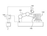
- Fig. 1 is a diagram illustrating the relationship between an information processing apparatus and a target object according to a first embodiment.
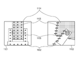
- Fig. 2 is a diagram schematically illustrating contact positions of the information processing apparatus and range measurement data according to the first embodiment.
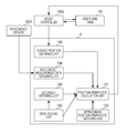
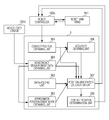
- Fig. 3 is a diagram illustrating a configuration of the information processing apparatus according to the first embodiment.
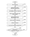
- Fig. 4 is a flowchart illustrating a procedure of a process according to the first embodiment.
- Fig. 5 is a diagram schematically illustrating the contact positions of the information processing apparatus and two-dimensional measurement data according to the first embodiment.
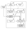
- Fig. 6 is a diagram illustrating a configuration of an information processing apparatus according to a second embodiment.
- Fig. 7 is a diagram illustrating a configuration of an information processing apparatus according to a third embodiment.
- Fig. 1 is a diagram illustrating the relationship between an information processing apparatus and a target object according to a first embodiment.
- Fig. 2 is a diagram schematically illustrating contact positions of the information processing apparatus and
- FIG. 8 is a flowchart illustrating a procedure of a process according to the third embodiment.
- Fig. 9 is a diagram illustrating the relationship between an information processing apparatus and a target object according to a fourth embodiment.
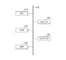
- Fig. 10 is a diagram illustrating a hardware configuration of the information processing apparatuses according to the present invention.
- Fig. 10 is a diagram illustrating a hardware configuration of information processing apparatuses according to the embodiments of the present invention.
- a CPU 1010 integrally controls devices connected to the CPU 1010 through a bus 1000.
- the CPU 1010 reads and executes processing steps and programs stored in a read only memory (ROM) 1020.
- ROM read only memory
- various processing programs, various device drivers, and the like of the embodiments which are stored in the ROM 1020 are temporarily stored in a random access memory (RAM) 1030, and executed by the CPU 1010 where appropriate.
- an input I/F 1040 receives input signals from external apparatuses (a display apparatus, an operation apparatus, and the like) in a format which may be processed by an information processing apparatus 1.
- an input I/F 1050 outputs signals to the external apparatus (the display apparatus) in a format which may be processed by the display apparatus.
- a method for measuring a position-orientation of a target object in accordance with accuracy information of contact positions of a robot hand and accuracy information of noncontact measurement data of a noncontact sensor is described.
- a position-orientation is calculated focusing on the noncontact measurement data and the contact positions which have small error distributions taking characteristic of the error distributions which are the accuracy information of the noncontact measurement data and the accuracy information of the contact positions into consideration.
- the position-orientation of the target object may be calculated with high accuracy.
- a noncontact sensor 1003 is attached to a robot arm 1001 having a robot hand 1002 attached thereto so as to measure a distance to a target object 1104 as illustrated in Fig. 1.
- a target object 1104 is grasped by the robot hand 1002
- an aggregation of range measurement points 1105 is measured as represented by a captured image 1101 of Fig. 2.
- the captured image 1101 is captured by an imaging device included in the noncontact sensor 1003.
- the noncontact sensor 1003 is positioned near the target object 1104, and therefore, it is highly likely that only a portion of the target object 1104 is measured as represented by the captured image 1101.
- the position-orientation of the target object 1104 having six degrees of freedom is to be calculated, it is likely that components of a position-orientation which are orthogonal to a surface of the captured image 1101 are not determined. Therefore, the calculation of a position-orientation of the target object 1104 is enabled using information on contact positions of the robot hand 1002 in addition to range measurement points 1105 in this embodiment. Furthermore, the position-orientation may be calculated with higher accuracy by calculating a position-orientation focusing on the noncontact measurement data and the contact positions having small error distributions taking the error distributions representing measurement accuracies of the range measurement points 1105 and contact points 1106 into consideration.
- Fig. 3 is a block diagram illustrating a configuration of the information processing apparatus 1. The configuration of the information processing apparatus 1 of this embodiment will be described hereinafter.
- a scene in which a target object 1104 installed in a predetermined position-orientation is grasped is simulated.
- a position-orientation of the target object 1104 is shifted. Therefore, the position-orientation of the target object 1104 is calculated in accordance with noncontact measurement data and contact positions of the robot hand 1002.
- the information processing apparatus 1 includes a data holding unit 102, an approximate position-orientation obtaining unit 103, a noncontact measurement data obtaining unit 104, a contact position obtaining unit 105, an accuracy obtaining unit 106, and a position-orientation calculation unit 107. Then a position-orientation of the target object 1104 is measured with high accuracy in accordance with accuracy of the contact positions of the robot hand 1102 and accuracy of the measurement data obtained by the noncontact sensor 1003. Furthermore, the information processing apparatus 1 transmits the calculated position-orientation to a robot controller 1005 and controls the robot arm hand 101 so that the robot arm hand 101 grasps the target object 1104. Note that the robot hand 1002 and the robot arm 1001 illustrated in Fig. 1 correspond to the robot arm hand 101 illustrated in Fig. 3.
- the robot arm hand 101 includes the six-axis robot arm 1001 and the robot hand 1002 attached to a tip end of the robot arm 1001.
- the tip end of the robot arm 1001 may be moved in an input arbitrary position-orientation under control of the robot controller 1005.
- position-orientations of joints of the robot arm 1001 and a position-orientation of the robot hand 1002 in a reference coordinate system of the robot arm 1001 are output in accordance with information on joint angles of the robot arm 1001 and information on a shape of the robot arm hand 101.
- the robot hand 1002 opens and closes the robot hand 1002 in accordance with an instruction so as to grasp an object.
- the robot hand 1002 includes a contact sensor attached thereto which obtains information on contact positions of the grasping robot hand.
- the noncontact sensor 1003 measures information on a distance to a point of a surface of the object to be measured.
- a noncontact sensor which outputs a range image having range values stored in individual pixels is used in this embodiment.
- the range image includes the pixels having depth information.
- an active noncontact sensor which captures reflection light of pattern light emitted by a projector or the like to the target object 1104 by a camera so as to measure a distance by triangulation is used.
- the noncontact sensor 1003 is not limited to this, and a noncontact sensor employing a time-of-flight method using flight time of light may be used. These active noncontact sensors may be suitably employed when an object having less roughness on a surface thereof is to be measured.
- a noncontact sensor employing a passive method for calculating depths of pixels by triangulation from an image captured by a stereo camera may be employed.
- the passive noncontact sensor is suitably employed in a case where an object having large roughness on a surface thereof is to be measured.
- any noncontact sensor may be used as long as the noncontact sensor measures a range image since such a noncontact sensor does not run the essence of the present invention.
- the data holding unit 102 holds information on a shape of the target object 1104 to be used when a position-orientation of the target object 1104 is estimated.
- an aggregation of three-dimensional points on a surface of the target object 1104 corresponds to the shape information.
- the shape information of the target object 1104 is to be used by the position-orientation calculation unit 107.
- the data holding unit 102 further holds following information: (1) an approximate position-orientation of the target object 1104 in the reference coordinate of the robot arm 1001; (2) a relative position-orientation between the robot arm 1001 and the noncontact sensor 1003; (3) a relative position-orientation between a contact sensor attached to the robot hand 1002 and the robot hand 1002; and (4) calibration information, such as accuracy information of noncontact measurement data and accuracy information of the contact positions.
- the calibration information is measured in advance.
- the approximate position-orientation obtaining unit 103 obtains an approximate position-orientation of the target object 1104 in the reference coordinate of the robot arm 1001.
- the approximate position-orientation of the target object 1104 is to be used by the position-orientation calculation unit 107. Furthermore, the approximate position-orientation of the target object 1104 is transmitted to the robot controller 1005 so as to be used for control of the robot arm hand 101.
- the noncontact measurement data obtaining unit 104 obtains an aggregation of three-dimensional points in the reference coordinate of the robot arm 1001 as noncontact measurement data measured by the noncontact sensor 1003 attached to the robot arm 1001.
- the noncontact measurement data is to be used by the position-orientation calculation unit 107.
- the contact position obtaining unit 105 obtains an aggregation of three-dimensional positions of contact positions of the robot hand 1002 obtained when contact is detected by the contact sensor attached to the robot hand 1002 in the reference coordinate of the robot arm 1001 (obtainment of contact position information).
- the obtained contact positions are to be used by the position-orientation calculation unit 107.
- the accuracy obtaining unit 106 obtains accuracy information of a group of the three-dimensional points (the noncontact measurement data) obtained by the noncontact measurement data obtaining unit 104 and accuracy information of the three-dimensional positions of the contact positions obtained by the contact position obtaining unit 105.
- the accuracy information corresponds to error distribution (variation values) of the three-dimensional points.
- a normalized covariance matrix is used as the error distribution.
- the error distribution is obtained by performing measurement on an object in which a three-dimensional position thereof is recognized in advance a plurality of times in advance by the noncontact sensor 1003 and the contact sensor.
- error distribution tables using a three-dimensional coordinate as a key are generated individually for noncontact measurement data and contact position data and are held in the data holding unit 102 as accuracy information. The held accuracy is to be used by the position-orientation calculation unit 107.
- the position-orientation calculation unit 107 calculates a position-orientation of the target object 1104 (position orientation obtainment). Specifically, a position-orientation of the target object 1104 is calculated in accordance with the following information: (1) the shape information of the target object 1104 held by the data holding unit 102; (2) the approximate position-orientation of the target object 1104 obtained by the approximate position-orientation obtaining unit 103; (3) the noncontact measurement data obtained by the noncontact measurement data obtaining unit 104; (4) the contact positions of the robot hand 1002 obtained by the contact position obtaining unit 105; and (5) the accuracy of the noncontact measurement data and the accuracy of the contact positions of the robot hand 1002 obtained by the accuracy obtaining unit 106.
- a position-orientation of the target object 1104 is calculated in accordance with a general iterative closest points (ICP) algorithm using the approximate position-orientation as an initial value.
- the calculated position-orientation is transmitted to the robot controller 1005 so that the robot arm hand 101 is controlled. In this way, assembly and arrangement of the target object 1104 are realized with high accuracy.
- the functional units are realized when the CPU 1010 develops the programs stored in the ROM 1020 in the RAM 1030 and executes processes in accordance with flowcharts described below. Furthermore, in a case where hardware is configured as replacement of a software process using the CPU 1010, a calculation unit and circuits corresponding to processes of the functional units described herein are configured.
- step S1010 the shape information of the target object 1104 held in the data holding unit 102, that is, the aggregation of the three-dimensional points on the surface of the target object 1104, is obtained.
- the three-dimensional points are included in a reference coordinate system of the target object 1104.
- step S1020 the approximate position-orientation obtaining unit 103 obtains an approximate position-orientation of the target object 1104 in the reference coordinate of the robot arm 1001. Specifically, the approximate position-orientation obtaining unit 103 reads the approximate position-orientation of the target object 1104 in the reference coordinate of the robot arm 1001 held in the data holding unit 102. ⁇ Step S1030>
- step S1030 the approximate position-orientation obtaining unit 103 transmits the approximate position-orientation of the target object 1104 obtained in step S1020 to the robot controller 1005.
- the robot controller 1005 controls the robot arm hand 101 so that the target object 1104 is grasped in predetermined positions.
- step S1040 the noncontact measurement data obtaining unit 104 obtains an aggregation of three-dimensional points in the reference coordinate of the robot arm 1001 as noncontact measurement data.
- the noncontact measurement data obtaining unit 104 obtains the group of the three-dimensional points from the noncontact sensor 1003 attached to the robot arm 1001.
- the group of the three-dimensional points obtained from the noncontact sensor 1003 is in a local coordinate system of the noncontact sensor 1003. Therefore, coordinates of the three-dimensional points in the local coordinate system of the noncontact sensor 1003 are transformed into those in the reference coordinate system of the robot arm 1001 in accordance with a relative position-orientation between the noncontact sensor 1003 and the robot arm 1001 and a position-orientation of the robot arm 1001 including the noncontact sensor 1003 attached thereto.
- the contact position obtaining unit 105 obtains an aggregation of three-dimensional coordinates in positions in which the robot hand 1001 is in contact with the target object 1104 in the reference coordinate of the robot arm 1001 as contact positions. Specifically, the contact position obtaining unit 105 obtains positions in which the robot hand 1002 is in contact with the target object 1104 from the contact sensor, not illustrated, attached to the robot hand 1002. The contact positions obtained by the contact sensor correspond to three-dimensional points in a local coordinate system of the contact sensor.
- step S1060 the accuracy obtaining unit 106 obtains accuracy information of the noncontact measurement data obtained in step S1040 and the accuracy information of the contact positions obtained in step S1050.
- error distribution corresponding to the three-dimensional points included in the aggregation of the three-dimensional points of the noncontact measurement data obtained in step S1040 is obtained as accuracy information of the three-dimensional points from the error distribution table of the noncontact measurement data which is accuracy information held by the data holding unit 102.
- the contact positions error distribution corresponding to the three-dimensional points included in the aggregation of the three-dimensional points of the contact positions obtained in step S1050 is obtained as accuracy information of the three-dimensional points from the error distribution table of the contact positions held by the data holding unit 102.
- the error distribution of the contact positions of the contact sensor spreads in a direction substantially orthogonal to normal lines on surfaces in the contact positions.
- step S1070 the position-orientation calculation unit 107 calculates a position-orientation of the target object 1104 in the reference coordinate of the robot arm 1001.
- the general ICP algorism is used for the position-orientation calculation.
- the ICP algorithm is a method for calculating a relative position-orientation between two groups of N-dimensional points by repeatedly performing association and position-orientation calculation.
- the noncontact measurement data and the contact positions in the reference coordinate of the robot arm 1001 which are obtained in step S1040 and step S1050, respectively, are determined as one of the groups of three-dimensional points. Furthermore, it is assumed that the group of the three-dimensional points in the reference coordinate system of the target object 1104 obtained in step S1010 is determined as the other of the groups of three-dimensional points.
- a position-orientation of the target object 1104 in the reference coordinate system of the robot arm 1001 may be calculated. Specifically, the calculation is performed by the following procedure.
- a three-dimensional point aggregation Q on the surface of the target object 1104 in the reference coordinate system of the target object 1104 obtained in step S1010 is subjected to coordinate transformation using the transformation matrix M.
- a three-dimensional point aggregation obtained after the transformation is denoted by "MQ”.
- N(e, ⁇ ) denotes normalized distributions of the normalized covariance matrices ⁇ .
- the transformation matrix M used for the transformation from the reference coordinate system of the target object 1104 to the reference coordinate system of the robot arm 1001, that is, a position-orientation of the target object 1104 in the reference coordinate system of the robot arm 1001, is calculated.
- the position-orientation of the target object 1104 may be calculated with high accuracy since characteristics of the accuracy information (the error distributions) are mutually compensated for.
- the noncontact measurement data obtaining unit 104 obtains a group of three-dimensional points measured by the noncontact sensor 1003.
- the noncontact measurement data obtaining unit 104 may obtain an image feature extracted from an image captured by a camera.
- the image feature is edge points
- the present invention is particularly effective in a scene illustrated in Fig. 5.
- accuracy of edge points is low in an edge direction detected from the image, the accuracy is high in a direction orthogonal to the edge direction as represented by ovals of the edge points 1205 illustrated in a side view 1202 of Fig. 5.
- no information is determined from a single edge point and error distribution infinitely spreads in the depth direction.
- a noncontact sensor 1003 and a camera are attached to a robot arm 1001 so that both of a three-dimensional point group supplied from the noncontact sensor 1003 and an image feature supplied from the camera may be obtained as noncontact measurement data by a noncontact measurement data obtaining unit 104.
- a position-orientation of the target object 1104 is calculated with high accuracy simultaneously using the noncontact measurement data and the contact positions using the maximum likelihood estimation utilizing the error distributions is illustrated in the foregoing configuration.
- the maximum likelihood estimation may not be used as a method for calculating a position-orientation of the target object 1104 simultaneously using the noncontact measurement data and the contact positions.
- a position-orientation of the target object 1104 may be calculated by weighted least-squares or the like using distribution of errors of the noncontact measurement data and distribution of errors of the contact points as weights.
- the weights may be determined in accordance with, in addition to the distribution, reliability of detection of image features and geometric features, such as range measurement points, signal intensity for detecting the contact points, or the number of detected points.
- a position-orientation is calculated focusing on the noncontact measurement data and the contact positions having small error distributions taking the accuracy information (the error distribution) of the noncontact measurement data and the accuracy information (the error distribution) of the contact positions of the robot hand 1002 having different tendencies into consideration.
- a position-orientation of the target object 1104 may be calculated with high accuracy while characteristics of the accuracy information (the error distributions) are mutually compensated for.
- a method for calculating a position-orientation of a target object 1104 by changing measurement data in accordance with accuracy information of contact positions of a robot hand 1002 and accuracy information of noncontact measurement data of a noncontact sensor 1003 so that only data having high accuracy is used will be described.
- Measurement accuracy of the noncontact sensor 1003 is likely to be degraded in a case where an object having low reflection luminance, a moving object, or an object out of a measurement available range is measured. Furthermore, measurement accuracy of a contact sensor attached to the robot hand 1002 may also be degraded in a case where a grasped object is slipped or flexible. If a position-orientation of the target object 1104 is calculated using unreliable measurement data of low accuracy, an inappropriate position-orientation may be calculated. Therefore, in this embodiment, a method for calculating a position-orientation of the target object 1104 with high accuracy by changing data to be used in accordance with accuracy of contact positions and accuracy of noncontact measurement data obtained by the noncontact sensor 1003 even if measurement data of low accuracy is mixed will be described.
- FIG. 6 A configuration of this embodiment is illustrated in Fig. 6. Only differences from the first embodiment will be described.
- a noncontact measurement data obtaining unit 204 obtains an aggregation of three-dimensional points in a reference coordinate of a robot arm 1001 and an aggregation of measurement reliabilities thereof as noncontact measurement data measured by the noncontact sensor 1003 attached to the robot arm 1001.
- a time-of-flight (TOF) sensor for example, is capable of calculating the measurement reliabilities in accordance with reflection intensity or the like
- a stereo sensor for example, is capable of calculating the measurement reliabilities in accordance with a matching degree of pattern matching or the like.
- a contact position obtaining unit 205 obtains an aggregation of three-dimensional points of the contact positions of the robot hand 1002 in the reference coordinate of the robot arm 1001 and an aggregation of measurement reliabilities obtained when contact is detected by the contact sensor attached to the robot hand 1002.
- the reliability of the contact sensor may be calculated in accordance with intensity, distribution, or the like of signals detected by the contact sensor.
- An accuracy obtaining unit 206 sets the measurement reliability obtained by the noncontact measurement data obtaining unit 204 as accuracy of a group of the three-dimensional points obtained by the noncontact measurement data obtaining unit 204. Similarly, the accuracy obtaining unit 206 sets the measurement reliability obtained by the contact position obtaining unit 205 as accuracy of the three-dimensional positions of the contact positions obtained by the contact position obtaining unit 205.
- a position-orientation calculation unit 207 calculates a position-orientation of the target object 1104. Specifically, as with the first embodiment, the position-orientation calculation unit 207 calculates a position-orientation of the target object 1104 in accordance with the following information: (1) shape information of the target object 1104 held by a data holding unit 202; (2) an approximate position-orientation of the target object 1104 obtained by an approximate position-orientation obtaining unit 203; (3) the noncontact measurement data obtained by the noncontact measurement data obtaining unit 204; (4) the contact positions of the robot hand 1002 obtained by the contact position obtaining unit 205; and (5) the accuracy of the noncontact measurement data and the accuracy of the contact positions of the robot hand 1002 obtained by the accuracy obtaining unit 206. Note that, here, the position-orientation calculation unit 207 calculates a position-orientation of the target object 1104 by selecting data to be used for the calculation of a position-orientation in accordance with the accuracy obtained by the accuracy obtaining unit 206.
- a processing flow of this embodiment is similar to the flowchart of the first embodiment illustrated in Fig. 4, and only differences are described hereinafter.
- Step S1040 The process from step S1010 to step S1030 of the first embodiment is similarly performed. ⁇ Step S1040>
- the noncontact measurement data obtaining unit 204 obtains an aggregation of three-dimensional points in the reference coordinate of the robot arm 1001 and an aggregation of measurement reliabilities thereof as noncontact measurement data.
- coordinates of the three-dimensional points in a local coordinate system of the noncontact sensor 1003 are transformed into those in the reference coordinate system of the robot arm 1001 in accordance with a relative position-orientation between the noncontact sensor 1003 and the robot arm 1001 and a position-orientation of the robot arm 1001 including the noncontact sensor 1003 attached thereto.
- step S1050 the contact position obtaining unit 205 obtains an aggregation of three-dimensional coordinates in positions in which the robot hand 1002 is in contact with the target object 1104 in the reference coordinate of the robot arm 1001 as contact positions and an aggregation of measurement reliabilities thereof.
- the three-dimensional points of the contact positions in the local coordinate system are transformed into those in the reference coordinate system of the robot arm 1001 in accordance with a relative position-orientation between the contact sensor and the robot hand 1002, a relative position-orientation between the robot arm 1001 and the robot hand 1002, and a position-orientation of the robot hand 1002.
- step S1060 the accuracy obtaining unit 206 sets measurement reliabilities as accuracy of the noncontact measurement data obtained in step S1040 and accuracy of the contact positions obtained in step S1050.
- step S1070 the position-orientation calculation unit 207 calculates a position-orientation of the target object 1104 in the reference coordinate of the robot arm 1001.
- the ICP algorism is used for the position-orientation calculation. Note that only noncontact measurement data having accuracy larger than a predetermined threshold value t1 is used for the position-orientation calculation. Furthermore, only contact points having accuracy larger than a predetermined threshold value t2 are used.
- a position-orientation of the target object 1104 may be calculated with high accuracy by changing data to be used in accordance with accuracy of contact positions and accuracy of noncontact measurement data obtained by the noncontact sensor 1003 even if measurement data of low accuracy is mixed.
- points to be used for the position-orientation calculation are selected by checking accuracy for each noncontact measurement data and each contact point.
- a position-orientation may be calculated only using contact points without using entire noncontact measurement data if mean accuracy, minimum accuracy, and maximum accuracy of the noncontact measurement data which have been checked are larger than a predetermined threshold value.
- a position-orientation may be calculated only using the noncontact measurement data.
- both of the accuracy of the noncontact measurement data and the accuracy of the contact points are smaller than the respective threshold values, at least one of the noncontact measurement data and the contact positions may be measured again so that the accuracy is obtained again and a position-orientation is calculated again.
- only one of the noncontact measurement data and the contact points which has higher accuracy may be used.
- a position-orientation of the target object 1104 may be calculated with high accuracy by changing data so that only data having high accuracy is used in accordance with the accuracy of the noncontact measurement data and the accuracy of contact positions of the robot hand 1002 even if measurement data of low accuracy is mixed.
- a method for calculating a position-orientation of a target object 1104 with higher accuracy by determining positions where the target object 1104 is grasped such that ambiguity of a position-orientation calculated in accordance with contact positions of a robot hand 1002 and noncontact measurement data of a noncontact sensor 1003 is reduced will be described.
- An apparatus configuration of this embodiment is the same as that of the first embodiment illustrated in Fig. 1.
- the target object 1104 is grasped and touched after grasping positions on the target object 1104 are determined such that smaller ambiguity of a calculated position-orientation is obtained and measurement accuracy of range measurement points 1105 and measurement accuracy of contact points 1106 are taken into consideration.
- a scene in which one of piled objects is grasped as a target object 1104 is estimated.
- An approximate position-orientation of the object to be grasped is obtained by performing noncontact measurement on the piled objects, and grasping positions are determined before the target object 1104 is grasped.
- a position-orientation of the target object 1104 is shifted. Therefore, the position-orientation of the target object 1104 is calculated in accordance with noncontact measurement data and contact positions of the robot hand 1002.
- Fig. 7 is a block diagram illustrating a configuration of an information processing apparatus 3 according to this embodiment. The configuration of the information processing apparatus 3 of this embodiment will now be described.
- the information processing apparatus 3 transmits a calculated position-orientation to a robot controller 1005 and controls a robot arm hand 101 so that the robot arm hand 101 grasps a target object 1104.
- the information processing apparatus 3 includes a contact position determination unit 308 in addition to a data holding unit 302, an approximate position-orientation obtaining unit 303, a noncontact measurement data obtaining unit 304, a contact position obtaining unit 305, an accuracy obtaining unit 306, and a position-orientation calculation unit 307.
- the approximate position-orientation obtaining unit 303 obtains an approximate position-orientation of the target object 1104 in a reference coordinate of the robot arm 1001.
- the noncontact sensor 1003 attached to the robot arm 1001 performs three-dimensional measurement on a scene including the target object 1104 so that a position-orientation of the target object 1104 is detected from an aggregation of obtained three-dimensional points in the reference coordinate of the robot arm 1001.
- the contact position determination unit 308 determines grasping positions of the target object 1104. Information on the determined grasping positions is supplied to the robot controller 1005 so as to be used for control of the grasping of the target object 1104.
- a process from step S3040 to step S3070 is the same as the process from step S1040 to step S1070 in the first embodiment. ⁇ Step S3010>
- step S3010 the approximate position-orientation obtaining unit 303 obtains information on a shape of the target object 1104 held in the data holding unit 302, that is, an aggregation of three-dimensional points and normal lines on a surface of the target object 1104.
- the three-dimensional points are included in a reference coordinate system of the target object 1104.
- a dictionary to be used for recognition of the target object 1104 to be performed in step S3020 is generated.
- a recognition method using spin images is utilized for detection of the target object 1104.
- a spin-images feature value is a local feature value calculated using a range image and a group of three-dimensional points. Therefore, the spin-images feature value is extracted from the shape information of the target object 1104 and held as the dictionary.
- a dictionary which is generated in advance and stored in the data holding unit 302 may be read.
- the recognition method using the spin images are disclosed in NPL 2. ⁇ Step S3020>
- step S3020 the approximate position-orientation obtaining unit 303 obtains an approximate position-orientation of the target object 1104 in the reference coordinate of the robot arm 1001.
- the noncontact sensor 1003 attached to the robot arm 1001 performs three-dimensional measurement on a scene including the target object 1104 and a position-orientation of the target object 1104 is detected from an aggregation of obtained three-dimensional points in the reference coordinate of the robot arm 1001.
- the recognition method using spin images is utilized for detection of the target object 1104.
- a spin-images feature value is extracted from the aggregation of the measured three-dimensional points and compared with the dictionary generated in step S3010 so that a position-orientation of the target object 1104 is calculated.
- the calculated position-orientation is used as an initial value and the position-orientation of the target object 1104 is refined by applying the ICP algorism to the shape information the target object 1104 and the aggregation of the measured three-dimensional points so that an approximate position-orientation is obtained.
- the three-dimensional points and the normal lines on the surface of the target object 1104 are determined as a local plane, distances between the measured three-dimensional points and the plane which are associated with each other are minimized so that a position-orientation of the target object 1104 is calculated.
- step S3025 the contact position determination unit 308 determines grasping positions of the target object 1104. Using the aggregation (measurement data) of the three-dimensional points obtained through the three-dimensional measurement performed by the noncontact sensor 1003 used when the approximate position-orientation is calculated in step S3020, ambiguity of the approximate position-orientation is calculated, and grasping positions which attain disambiguation is determined.
- the ambiguity of the approximate position-orientation is calculated by obtaining a Jacobian matrix from the shape information of the target object 1104 (the aggregation of the three-dimensional points and the normal lines on the surface of the target object 1104) and the aggregation (measurement data) of the measured three-dimensional points.
- the Jacobian matrix is a value indicating a degree of change of parameters of six degrees of freedom of a position-orientation obtained when a correspondence distance of geometric features which are focused on when a position-orientation of the target object 1104 is to be calculated is changed.
- the Jacobian matrix uses first-order partial derivatives of elements of a position and an orientation as elements in a case where distances between points in a three-dimensional space and a plane are set as functions of the position and the orientation.
- the Jacobian matrix of the geometric feature is checked, one of the parameters of the six degrees of freedom of the position-orientation which is likely to be affected by the geometric feature is recognized.
- influence on the parameter is small, that is, positioning fails since the parameter is not determined or positioning may not be performed with sufficient accuracy.
- a method for obtaining the Jacobian matrix of a geometric feature will be described.
- step S3020 the calculation of a position-orientation is performed in accordance with the ICP algorism in which the three-dimensional points and the normal lines (shape information) on the surface of the target object 1104 are determined as a local plane and a distance between the local plane and the associated measured three-dimensional points (measurement data) is minimized.
- the measurement data is data of the reference coordinate system of the robot arm 1001 and the shape information of the target object 1104 is data of the reference coordinate system of the target object 1104.
- a transformation parameter s (s1, s2, s3, s4, s5, s6) T for transformation from the reference coordinate system of the target object 1104 to the reference coordinate system of the robot arm 1001 so that a Jacobian matrix J 3D is calculated as follows.
- Expression 5 indicates an orientation transformation matrix for transformation from the reference coordinate system of the target object 1104 to the reference coordinate system of the robot arm 1001, and "(x m , y m , z m ) T " represents coordinates of the three-dimensional points of the shape information in the reference coordinate system of the target object 1104.
- a Jacobian matrix J of m rows by 6 columns obtained by connecting the m Jacobian matrices J 3D of 1 row by 6 columns (m is the number of correspondence points) is used
- a minor change between the position-orientation and the observation data may be represented as an error function of a first-order approximation of (a minor change ⁇ of) the position-orientation as represented by Math. 7.
- This is a relational expression representing a minor change of an observation data position caused by a minor change of a position-orientation.
- a covariance matrix Cov( ⁇ ) of the position-orientation is calculated from a covariance matrix Cov(e) of the measurement data in accordance with a framework of error back propagation.
- Standard deviations of the three-dimensional points of the measurement data are obtained from the accuracy obtaining unit 306 as accuracy of the measurement data and are set as " ⁇ range j ".
- the covariance matrix Cov(e) is represented by Math. 8 below using " ⁇ range j ".
- the covariance Cov( ⁇ ) of the position-orientation is calculated using the covariance Cov(e) of the measurement data and the Jacobian matrices J corresponding to the measurement data as follows.
- the covariance matrix Cov( ⁇ ) representing ambiguity of an estimated position-orientation parameter is calculated.
- a maximum eigenvector u of the covariance matrix Cov( ⁇ ) represents the most ambiguous direction of a position-orientation among position-orientations calculated as approximate position-orientations.
- the grasping positions of the target object 1104, that is, the contact points used for the position-orientation calculation in step S3070, have error distribution which spreads in directions orthogonal to normal lines of a surface of a robot hand 1002 as represented by the range measurement points 1105 in Fig. 2. Therefore, to reduce the ambiguity of the position-orientation calculation, points having normal lines nearest to the maximum eigenvector u are selected from the shape information of the target object 1104 so as to be determined as the grasping positions.
- step S3030 the contact position determination unit 308 supplies the grasping positions determined in step S3025 and the approximate position-orientation of the target object 1104 obtained in step S3020 to the robot controller 1005 which controls the robot arm hand 101 so that the target object 1104 is grasped.
- step S3070 the position-orientation calculation unit 307 calculates a position-orientation of the target object 1104 by the same process as step S3010.
- a transformation matrix M' which maximizes Math. 3 is calculated by the maximum likelihood estimation using the correspondence distance e as a measured three-dimensional point (measurement data) associated with the local plane represented by the three-dimensional points and the normal lines (the shape information) on the surface of the target object 1104.
- step S3080 the position-orientation calculation unit 307 calculates a covariance matrix representing the ambiguity of the position-orientation calculated in step S3070 by the method described in step S3025. Note that, in step S3070, both of the noncontact measurement data and the contact points are used as the measurement data for calculation of the position-orientation, and therefore, both of the noncontact measurement data and the contact points are used also for calculation the ambiguity. If the maximum eigenvalue (representing distribution in a direction of the largest variation of the calculated position-orientation) of the calculated covariance matrix is equal to or smaller than a predetermined threshold value, the calculation of the position-orientation is terminated, and otherwise, the process returns to step S3020 so that the measurement is performed again.
- the target object 1104 is grasped and touched after the grasping positions on the target object 1104 are determined such that smaller ambiguity of a calculated position-orientation is obtained and the position-orientation of the target object 1104 may be calculated with high accuracy taking accuracy of the noncontact measurement data and accuracy of the contact positions of the robot hand 1002 having different tendencies into consideration.
- grasping positions are determined only using ambiguity of a calculated position-orientation.
- the shape information of the robot hand 1002 may be additionally used so that it is determined whether the target object 1104 may be grasped in the determined grasping positions.
- simulation may be performed using the shape information of the robot hand 1002, the position-orientation of the target object 1104, the shape information of the target object 1104, and the three-dimensional measurement data of the scene so as to determine whether the target object 1104 may be grasped in the calculated grasping positions, and the normal lines of the aggregation of the surface points of the target object 1104 may be checked starting from one of the normal lines which is nearest to the maximum eigenvector u.
- the target object 1104 is grasped in the grasping positions such that smaller ambiguity of a calculated position-orientation is obtained, the noncontact measurement data and the contact positions of the robot hand 1002 which have different tendencies may be reliably obtained, and accordingly, the position-orientation of the target object 1104 may be calculated with high accuracy.
- a contact position is added by controlling a robot hand 1002 such that ambiguity of a position-orientation calculated from the contact positions of the robot hand 1002 and noncontact measurement data of a noncontact sensor 1003 is reduced after a target object 1104 is grasped.
- FIG. 9 A configuration of an apparatus of this embodiment is illustrated in Fig. 9.
- a point or a plane on a surface of a target object 1104 is determined such that smaller ambiguity of a calculated position-orientation of the target object 1104 is obtained and the target object 1104 is touched by a contact finger 3007 included in the robot hand 1002 in the point or the plane, so that a contact position is added.
- a position-orientation is calculated again using an aggregation of the added contact position and contact positions obtained before the addition and noncontact measurement data obtained by a noncontact sensor 1003 so that a position-orientation of the target object 1104 is calculated with higher accuracy.
- a scene in which one of piled objects is grasped as a target object 1104 is estimated.
- An approximate position-orientation of the object to be grasped is obtained by performing noncontact measurement on the piled objects, and grasping positions are determined before the target object 1104 is grasped.
- a position-orientation of the target object 1104 is shifted. Therefore, the position-orientation of the target object 1104 is calculated in accordance with noncontact measurement data and contact positions of the robot hand 1002.
- a configuration of this embodiment is the same as that of the third embodiment illustrated in Fig. 7, and only differences are described hereinafter.
- the contact position determination unit 308 determines grasping positions of the target object 1104. Furthermore, the contact position determination unit 308 determines a position to be touched by the contact finger 3007 so as to additionally obtain a contact position. Information on the determined grasping positions and information on the contact position is supplied to the robot controller 1005 so as to be used for control of the grasping and touching of the target object 1104.
- a process in step S3010 is the same as that of the third embodiment.
- a first loop of a process from step S3020 to step S3080 is the same as that of the third embodiment.
- a target object 1104 is not grasped again but a contact position is additionally determined by bringing the contact finger 3007 to contact with the target object 1104. Processes in steps in the second loop onwards will be described hereinafter.
- step S3020 the approximate position-orientation obtaining unit 303 obtains an approximate position-orientation of a target object 1104 in a reference coordinate of a robot arm 1001. Specifically, a position-orientation of the target object 1104 calculated in step S3070 in a preceding loop is set as an approximate position-orientation.
- step S3025 the contact position determination unit 308 determines a contact position of the target object 1104.
- the contact position determination unit 308 calculates ambiguity of the position-orientation of the target object 1104 calculated in step S3070 in the preceding loop which is set as the approximate position-orientation and determines a contact position which attains disambiguation. That is, a Jacobian matrix is obtained from noncontact measurement data, the contact positions, and shape information of the target object 1104 (an aggregation of three-dimensional points and normal lines on a surface of the target object 1104) which have been used for calculation of a position-orientation of the target object 1104 so that the ambiguity is calculated.
- a method for calculating the contact position is the same as the method for calculating the grasping positions in step S3025 according to the third embodiment.
- step S3030 the contact position determined in step S3025 and the approximate position-orientation of the target object 1104 obtained in step S3020 are supplied to the robot controller 1005 which controls the robot arm hand 101 so that a finger of the robot hand 1002 touches the surface of the target object 1104.
- step S3040 the noncontact measurement data obtaining unit 304 obtains an aggregation of three-dimensional points in the reference coordinate of the robot arm 1001 as noncontact measurement data. Note that noncontact measurement data obtained in the preceding processing loop may be stored so as to be utilized again. ⁇ Step S3050>
- step S3050 the contact position obtaining unit 305 obtains a position which is touched by the robot hand 1002 in step S3030.
- An aggregation of three-dimensional coordinates obtained by adding the obtained contact position to the contact positions obtained in the preceding loop is output as contact positions to be used in the following steps.
- step S3060 the accuracy obtaining unit 306 obtains accuracy of the noncontact measurement data obtained in step S3040 and accuracy of the contact positions obtained in step S3050.
- step S3070 as with the third embodiment, the position-orientation calculation unit 307 calculates a position-orientation of the target object 1104. ⁇ Step S3080>
- step S3080 the position-orientation calculation unit 307 calculates a covariance matrix representing the ambiguity of the position-orientation calculated in step S3070 by the method described in step S3025. If the maximum eigenvalue (representing distribution in a direction of the largest variation of the calculated position-orientation) of the calculated covariance matrix is equal to or smaller than a predetermined threshold value, the calculation of a position-orientation is terminated, and otherwise, the process returns to step S3020 so that another contact position is measured.
- a position-orientation of the target object 1104 may be calculated by successively adding contact positions on the target object 1104 such that smaller ambiguity of the calculated position-orientation is obtained and a position-orientation of the target object 1104 may be calculated with high accuracy.
- a contact position is added using the contact finger 3007 as illustrated in Fig. 8.
- a device to be used to add a contact position is not limited to this. If a plurality of robot arms 1002 are used, one of the robot arms 1002 which is not grasping a target object 1104 may be used to add a contact position. Furthermore, if the target object 1104 is not moved when being touched, a contact position may be added without grasping the target object 1104.
- a contact position on the target object 1104 is successively added such that smaller ambiguity of a calculated position-orientation is obtained.
- the noncontact measurement data and the contact positions of the robot hand 1002 which have different tendencies may be reliably obtained, and accordingly, a position-orientation of the target object 1104 may be calculated with high accuracy.
- the present invention may also be realized by executing the following process. Specifically, software (programs) which realizes the functions of the foregoing embodiments is supplied to a system or an apparatus through a network or various storage media, and a computer (or a CPU, an MPU, or the like) of the system or the apparatus reads and executes the programs.
- a position-orientation is calculated focusing on the noncontact measurement data and the contact positions having small error distributions taking the accuracy (error distribution) of the noncontact measurement data and the accuracy (error distribution) of the contact positions of the robot hand 1002 having different tendencies into consideration.
- a position-orientation of the target object 1104 may be calculated with high accuracy without increasing the number of measurement apparatuses while characteristics of the accuracy information (the error distributions) are mutually compensated for.
- the measurement data is changed so that only data having high accuracy is used in accordance with the accuracy of the noncontact measurement data and the accuracy of the contact positions of the robot hand 1002.
- a position-orientation of the target object 1104 may be calculated with high accuracy without increasing the number of measurement apparatuses even if measurement data of low accuracy is mixed.
- the target object 1104 is grasped in positions on the target object 1104 such that smaller ambiguity of a calculated position-orientation is obtained.
- the noncontact measurement data and the contact positions of the robot hand 1002 which have different tendencies may be reliably obtained, and accordingly, the position-orientation of the target object 1104 may be calculated with high accuracy without increasing the number of measurement apparatuses.
- a contact position on the target object 1104 is successively added such that smaller ambiguity of a calculated position-orientation is obtained.
- the robot controller 1005 at least controls a movement of the robot arm 1001 and the robot hand 1002 to an arbitrary position-orientation and a grasping operation and outputs a state of a robot including position-orientations and joint angles of the robot arm 1001 and the robot hand 1002.
- the robot controller 1005 may control the robot arm hand 101 by receiving a position-orientation of a tip end of the robot arm 1001, a position-orientation of an object to be grasped, and information on joint angles of the robot arm 1001.
- Any shape of the robot arm 1001 may be employed as long as the robot has at least one operation portion.
- a plurality of arms may be provided or a plurality of robots may be provided.
- a six-axis robot, a scholar robot, or a parallel link robot may be used, and a shape of the robot is not restricted.
- an unsubstantial robot in simulation may be used.
- the robot hand 1002 has a mechanism for grasping a component, and the mechanism may have any configuration as long as the mechanism detects grasping and contacting.
- a mechanism of two fingers or multi-fingers may be used or a mechanism of a suction hand may be employed.
- a finger for contact measurement may be provided.
- an unsubstantial robot hand in simulation may be used.
- the data holding unit at least holds information on a shape of the target object 1104, information on a shape of the robot arm 1001, and calibration information which are to be used for estimation of a position-orientation of the target object 1104.
- the information on the shape of the target object 1104 may be an aggregation of geometric features, such as three-dimensional points and normal lines.
- the information on the shape of the target object 1104 may represent a three-dimensional mesh model or an analytic curved surface model, such as a CAD model.
- the calibration information may be the following information: an approximate position-orientation of the target object 1104 in the reference coordinate of the robot arm 1001; a relative position-orientation between the robot arm 1001 and the noncontact sensor 1003; a relative position-orientation between the contact sensor attached to the robot hand 1002 and the robot hand 1002; and information on accuracy of noncontact measurement data, information on accuracy of contact positions, a camera parameter of the measurement apparatus, and the like.
- the data holding unit may be any form, such as an HDD, an SSD, a memory, and a tape drive, as long as the data holding unit is capable of holding data.
- the approximate position-orientation obtaining unit at least obtains an approximate position-orientation of the target object 1104 in the reference coordinate of the robot arm 1001.
- the approximate position-orientation obtaining unit may read a position-orientation from the data holding unit or may obtain a position-orientation of the target object 1104 from measurement data obtained by measuring the target object 1104 by the noncontact sensor 1003 or a camera attached to the robot arm 1001 or installed in an environment.
- a recognition method based on feature values, such as spin images, or a method based on template matching may be used for calculation of a position-orientation using measurement data.
- a model fitting method using the ICP algorithm or the like may be used.
- the noncontact measurement data obtaining unit at least obtains noncontact measurement data of the target object 1104 in the reference coordinate of the robot arm 1001.
- the noncontact measurement data may be measured by the noncontact sensor 1003 attached to the robot arm 1001 or installed in the environment or data which is measured in advance may be read from a storage device as the noncontact measurement data.
- the noncontact measurement data may be a two-dimensional image or a range image, or may be an aggregation of three-dimensional points, normal lines of the three-dimensional points, and three-dimensional features.
- the noncontact measurement data may be an aggregation of geometric features, such as edges or feature points detected in a two-dimensional image, as long as the noncontact measurement data is information obtained by measuring the target object 1104 in a noncontact manner. If the obtained noncontact measurement data is a local coordinate system, the noncontact measurement data may be transformed into that in the reference coordinate of the robot arm 1001 using the calibration information held in the data holding unit.
- the contact position obtaining unit at least obtains contact positions in the target object 1104 in the reference coordinate of the robot arm 1001.
- the contact positions may be obtained by directly detecting touches by the contact sensor or may be obtained indirectly detecting touches by detecting loads applied to the robot hand 1002 or fingers. Data measured in advance may be read from the storage device. If the obtained contact positions are in a local coordinate system, the contact positions may be transformed into those in the reference coordinate of the robot arm 1001 using the calibration information held in the data holding unit.
- the accuracy obtaining unit at least obtains accuracy information of the noncontact measurement data obtained by the noncontact measurement data obtaining unit and accuracy information of the contact positions obtained by the contact position obtaining unit.
- Data measured in advance may be read from the storage device. Any expression may be used for representing the accuracy information as long as the accuracy of the noncontact measurement data and the accuracy of the contact position are represented. Error distribution or measurement reliability may be used. Furthermore, a degree of accuracy may be set high when the number of similar measurement points is large, or brightness of a captured image or intensity of geometric features may be used.
- the error distribution may be a normalized covariance matrix or a variance of normal distribution.
- a table of error distributions which is generated by performing measurement a plurality of times in advance using a three-dimensional coordinate as a key may be used, a function may be assigned to the table, or the table may be modeled and used as a parameter.
- the key of the table and the function is not limited to the three-dimensional coordinate but also brightness of pixels, intensity of geometric features, or a direction of a plane.
- the position orientation calculation unit at least obtains a position-orientation of the target object 1104 in the reference coordinate of the robot arm 1001 in accordance with the following information: (1) information on a shape of the target object 1104 held by the data holding unit; (2) the approximate position-orientation of the target object 1104 obtained by the approximate position-orientation obtaining unit; (3) the noncontact measurement data obtained by the noncontact measurement data obtaining unit; (4) the contact positions of the robot hand 1002 obtained by the contact position obtaining unit; and (5) the accuracy of the noncontact measurement data and the accuracy of the contact positions of the robot hand 1002 obtained by the accuracy obtaining unit.
- the position-orientation may be calculated by the ICP algorithm.
- a similarity degree between a geometric feature extracted from the information on the shape of the target object 1104 and a geometric feature extracted from the noncontact measurement data and the contact positions is measured and a position-orientation may be calculated in accordance with a distance between geometric features having similarity.
- a distance between points or a distance between a point and a plane may be used as a distance between shape information of the target object 1104 and the noncontact measurement data and the contact positions.
- an optimization method such as the maximum likelihood estimation or the least-squares estimation, may be used for the calculation of a position-orientation, or a position-orientation which has the highest evaluation value based on a distance may be searched for by full search.
- the accuracy of the noncontact measurement data and the accuracy of the contact positions may be used as a covariance matrix in the maximum likelihood estimation or a weight of the least-squares estimation, or may be used as a weight of the evaluation value.
- data having accuracy which is equal to or smaller than a predetermined threshold value may not be used for the calculation of a position-orientation.
- a position-orientation may be calculated only using the contact points without using the entire noncontact measurement data if mean accuracy, minimum accuracy, and maximum accuracy of the noncontact measurement data which have been checked are larger than a predetermined threshold value.
- the position-orientation may be calculated only using the noncontact measurement data if the mean accuracy and the like of the contact points are larger than a predetermined threshold value.
- both of the accuracy of the noncontact measurement data and the accuracy of the contact points are smaller than the respective threshold values, at least one of the noncontact measurement data and the contact positions may be measured again so that the accuracy is obtained again and the position-orientation is calculated again.
- only one of the noncontact measurement data and the contact points which has higher accuracy may be used.
- the contact position determination unit at least determines at least one of the grasping positions and the contact positions of the target object 1104 so that smaller ambiguity of a calculated position-orientation is obtained.
- the grasping positions and the contact positions may be determined by selecting points or planes having normal lines which extend in a direction the most similar to the most ambiguous direction of the calculated position-orientation of the target object 1104. Moreover, it is determined whether the grasping positions and the contact positions are available for touching using the shape information of the robot hand 1002 and only touchable positions may be selected.
- Embodiments of the present invention can also be realized by a computer of a system or apparatus that reads out and executes computer executable instructions recorded on a storage medium (e.g., non-transitory computer-readable storage medium) to perform the functions of one or more of the above-described embodiments of the present invention, and by a method performed by the computer of the system or apparatus by, for example, reading out and executing the computer executable instructions from the storage medium to perform the functions of one or more of the above-described embodiments.
- the computer may comprise one or more of a central processing unit (CPU), micro processing unit (MPU), or other circuitry, and may include a network of separate computers or separate computer processors.
- the computer executable instructions may be provided to the computer, for example, from a network or the storage medium.
- the storage medium may include, for example, one or more of a hard disk, a random-access memory (RAM), a read only memory (ROM), a storage of distributed computing systems, an optical disk (such as a compact disc (CD), digital versatile disc (DVD), or Blu-ray Disc (BD) TM ), a flash memory device, a memory card, and the like.
Landscapes
- Engineering & Computer Science (AREA)
- Robotics (AREA)
- Mechanical Engineering (AREA)
- Human Computer Interaction (AREA)
- Multimedia (AREA)
- General Physics & Mathematics (AREA)
- Physics & Mathematics (AREA)
- Health & Medical Sciences (AREA)
- General Health & Medical Sciences (AREA)
- Orthopedic Medicine & Surgery (AREA)
- Manipulator (AREA)
- Length Measuring Devices By Optical Means (AREA)
- Length Measuring Devices With Unspecified Measuring Means (AREA)
Priority Applications (1)
| Application Number | Priority Date | Filing Date | Title |
|---|---|---|---|
| US15/533,960 US10335963B2 (en) | 2014-12-09 | 2015-11-17 | Information processing apparatus, information processing method, and program |
Applications Claiming Priority (2)
| Application Number | Priority Date | Filing Date | Title |
|---|---|---|---|
| JP2014-249426 | 2014-12-09 | ||
| JP2014249426A JP6415291B2 (ja) | 2014-12-09 | 2014-12-09 | 情報処理装置、情報処理方法、プログラム |
Publications (1)
| Publication Number | Publication Date |
|---|---|
| WO2016092749A1 true WO2016092749A1 (en) | 2016-06-16 |
Family
ID=56106983
Family Applications (1)
| Application Number | Title | Priority Date | Filing Date |
|---|---|---|---|
| PCT/JP2015/005745 WO2016092749A1 (en) | 2014-12-09 | 2015-11-17 | Information processing apparatus, information processing method, and program |
Country Status (3)
| Country | Link |
|---|---|
| US (1) | US10335963B2 (ja) |
| JP (1) | JP6415291B2 (ja) |
| WO (1) | WO2016092749A1 (ja) |
Families Citing this family (27)
| Publication number | Priority date | Publication date | Assignee | Title |
|---|---|---|---|---|
| JP6415026B2 (ja) * | 2013-06-28 | 2018-10-31 | キヤノン株式会社 | 干渉判定装置、干渉判定方法、コンピュータプログラム |
| JP6415291B2 (ja) * | 2014-12-09 | 2018-10-31 | キヤノン株式会社 | 情報処理装置、情報処理方法、プログラム |
| JP6582530B2 (ja) * | 2015-05-11 | 2019-10-02 | 富士通株式会社 | 支援プログラム、支援方法および支援装置 |
| CN106945034B (zh) * | 2016-01-07 | 2021-09-03 | 鸿富锦精密电子(郑州)有限公司 | 机器人点位调节方法与系统 |
| JP6657132B2 (ja) | 2017-02-27 | 2020-03-04 | 富士フイルム株式会社 | 画像分類装置、方法およびプログラム |
| JP2018161700A (ja) * | 2017-03-24 | 2018-10-18 | キヤノン株式会社 | 情報処理装置、システム、情報処理方法、製造方法 |
| EP3639167A4 (en) * | 2017-06-16 | 2021-02-17 | Bayerische Motoren Werke Aktiengesellschaft | METHOD AND DEVICE FOR SELECTING A CARD FOR A MOVING OBJECT, SYSTEM AND VEHICLE / ROBOT |
| US11065761B2 (en) * | 2017-07-25 | 2021-07-20 | Dematic Corp. | Robotic picking training technique |
| JP6880457B2 (ja) * | 2017-11-14 | 2021-06-02 | オムロン株式会社 | 把持方法、把持システム及びプログラム |
| US10792809B2 (en) * | 2017-12-12 | 2020-10-06 | X Development Llc | Robot grip detection using non-contact sensors |
| JP6587195B2 (ja) * | 2018-01-16 | 2019-10-09 | 株式会社Preferred Networks | 触覚情報推定装置、触覚情報推定方法、プログラム及び非一時的コンピュータ可読媒体 |
| JP6988531B2 (ja) * | 2018-02-06 | 2022-01-05 | トヨタ自動車株式会社 | ロボット |
| JP7052564B2 (ja) * | 2018-05-29 | 2022-04-12 | オムロン株式会社 | 視覚センサシステム、制御方法およびプログラム |
| JP7163116B2 (ja) * | 2018-09-14 | 2022-10-31 | 株式会社東芝 | 情報処理装置及びピッキングシステム |
| US11241795B2 (en) * | 2018-09-21 | 2022-02-08 | Beijing Jingdong Shangke Information Technology Co., Ltd. | Soft package, robot system for processing the same, and method thereof |
| JP6697204B1 (ja) | 2019-01-25 | 2020-05-20 | 株式会社Mujin | ロボットシステムの制御方法、非一過性のコンピュータ読取可能な記録媒体及びロボットシステムの制御装置 |
| US10456915B1 (en) * | 2019-01-25 | 2019-10-29 | Mujin, Inc. | Robotic system with enhanced scanning mechanism |
| US10870204B2 (en) | 2019-01-25 | 2020-12-22 | Mujin, Inc. | Robotic system control method and controller |
| WO2020184678A1 (ja) | 2019-03-14 | 2020-09-17 | 株式会社東京精密 | 三次元測定システム及び三次元測定方法 |
| JP7400183B2 (ja) | 2020-03-04 | 2023-12-19 | 株式会社東京精密 | 三次元測定システム及び三次元測定方法 |
| JP6725862B1 (ja) | 2019-03-14 | 2020-07-22 | 株式会社東京精密 | 三次元測定システム及び三次元測定方法 |
| JP7458578B2 (ja) | 2020-03-04 | 2024-04-01 | 株式会社東京精密 | 三次元測定システム及び三次元測定方法 |
| EP3738725B1 (en) | 2019-05-15 | 2022-02-16 | Omron Corporation | Measurement system, measurement device, measurement method, and measurement program |
| JP7307592B2 (ja) * | 2019-05-24 | 2023-07-12 | キヤノン株式会社 | 計測装置、撮像装置、制御方法及びプログラム |
| CN114051443A (zh) * | 2019-07-03 | 2022-02-15 | 首选网络株式会社 | 信息处理装置、机器人系统以及信息处理方法 |
| WO2021064925A1 (ja) * | 2019-10-02 | 2021-04-08 | 富士通株式会社 | 生成方法、生成プログラムおよび情報処理装置 |
| JP7388970B2 (ja) | 2020-04-06 | 2023-11-29 | ファナック株式会社 | ロボットシステム |
Citations (4)
| Publication number | Priority date | Publication date | Assignee | Title |
|---|---|---|---|---|
| JPH05288543A (ja) * | 1992-04-07 | 1993-11-02 | Fujitsu Ltd | 視覚情報と触覚情報とを統合した認識装置 |
| JP2008014691A (ja) * | 2006-07-04 | 2008-01-24 | Japan Aerospace Exploration Agency | ステレオ画像計測方法とそれを実施する装置 |
| JP2008309671A (ja) * | 2007-06-15 | 2008-12-25 | Ihi Corp | 物体認識方法および装置 |
| JP2013032922A (ja) * | 2011-08-01 | 2013-02-14 | Hitachi Ltd | 3次元寸法測定方法 |
Family Cites Families (8)
| Publication number | Priority date | Publication date | Assignee | Title |
|---|---|---|---|---|
| KR20060015557A (ko) * | 2003-04-28 | 2006-02-17 | 스티븐 제임스 크램톤 | 외골격을 구비한 cmm 암 |
| JP5105147B2 (ja) * | 2006-08-28 | 2012-12-19 | 株式会社安川電機 | ロボットおよび制御方法 |
| JP5505138B2 (ja) | 2010-07-05 | 2014-05-28 | 株式会社安川電機 | ロボット装置およびロボット装置による把持方法 |
| US9437005B2 (en) * | 2011-07-08 | 2016-09-06 | Canon Kabushiki Kaisha | Information processing apparatus and information processing method |
| JP6000579B2 (ja) * | 2012-03-09 | 2016-09-28 | キヤノン株式会社 | 情報処理装置、情報処理方法 |
| JP6415291B2 (ja) * | 2014-12-09 | 2018-10-31 | キヤノン株式会社 | 情報処理装置、情報処理方法、プログラム |
| GB201509341D0 (en) * | 2015-05-29 | 2015-07-15 | Cambridge Medical Robotics Ltd | Characterising robot environments |
| JP2017177294A (ja) * | 2016-03-31 | 2017-10-05 | キヤノン株式会社 | ロボット制御装置、ロボット制御方法、ロボットシステムおよびコンピュータプログラム |
-
2014
- 2014-12-09 JP JP2014249426A patent/JP6415291B2/ja active Active
-
2015
- 2015-11-17 WO PCT/JP2015/005745 patent/WO2016092749A1/en active Application Filing
- 2015-11-17 US US15/533,960 patent/US10335963B2/en active Active
Patent Citations (4)
| Publication number | Priority date | Publication date | Assignee | Title |
|---|---|---|---|---|
| JPH05288543A (ja) * | 1992-04-07 | 1993-11-02 | Fujitsu Ltd | 視覚情報と触覚情報とを統合した認識装置 |
| JP2008014691A (ja) * | 2006-07-04 | 2008-01-24 | Japan Aerospace Exploration Agency | ステレオ画像計測方法とそれを実施する装置 |
| JP2008309671A (ja) * | 2007-06-15 | 2008-12-25 | Ihi Corp | 物体認識方法および装置 |
| JP2013032922A (ja) * | 2011-08-01 | 2013-02-14 | Hitachi Ltd | 3次元寸法測定方法 |
Also Published As
| Publication number | Publication date |
|---|---|
| JP2016109630A (ja) | 2016-06-20 |
| JP6415291B2 (ja) | 2018-10-31 |
| US10335963B2 (en) | 2019-07-02 |
| US20170326739A1 (en) | 2017-11-16 |
Similar Documents
| Publication | Publication Date | Title |
|---|---|---|
| WO2016092749A1 (en) | Information processing apparatus, information processing method, and program | |
| US20200230821A1 (en) | Information processing apparatus, information processing method, and storage medium | |
| JP6271953B2 (ja) | 画像処理装置、画像処理方法 | |
| JP6573354B2 (ja) | 画像処理装置、画像処理方法、及びプログラム | |
| US20150283704A1 (en) | Information processing apparatus and information processing method | |
| JP5671281B2 (ja) | 位置姿勢計測装置、位置姿勢計測装置の制御方法及びプログラム | |
| US20130245828A1 (en) | Model generation apparatus, information processing apparatus, model generation method, and information processing method | |
| JP5746477B2 (ja) | モデル生成装置、3次元計測装置、それらの制御方法及びプログラム | |
| US10325336B2 (en) | Information processing apparatus, information processing method, and program | |
| US9639942B2 (en) | Information processing apparatus, information processing method, and storage medium | |
| US10203197B2 (en) | Range measurement apparatus and range measurement method | |
| JP6677522B2 (ja) | 情報処理装置、情報処理装置の制御方法およびプログラム | |
| WO2011148596A1 (ja) | 顔特徴点位置補正装置、顔特徴点位置補正方法および顔特徴点位置補正プログラム | |
| JP2011027724A (ja) | 3次元計測装置、その計測方法及びプログラム | |
| US20180247150A1 (en) | Information processing device, information processing method, and article manufacturing method | |
| US9914222B2 (en) | Information processing apparatus, control method thereof, and computer readable storage medium that calculate an accuracy of correspondence between a model feature and a measurement data feature and collate, based on the accuracy, a geometric model and an object in an image | |
| JP6626338B2 (ja) | 情報処理装置、情報処理装置の制御方法、およびプログラム | |
| JP5976089B2 (ja) | 位置姿勢計測装置、位置姿勢計測方法、およびプログラム | |
| US20120076355A1 (en) | 3d object tracking method and apparatus | |
| WO2016084316A1 (en) | Information processing apparatus, information processing method, and program | |
| CN111742349B (zh) | 信息处理装置、信息处理方法以及信息处理存储介质 | |
| US20240083038A1 (en) | Assistance system, image processing device, assistance method and non-transitory computer-readable storage medium | |
| US20230011093A1 (en) | Adjustment support system and adjustment support method | |
| TWI730482B (zh) | 平面動態偵測系統及偵測方法 | |
| US20230154162A1 (en) | Method For Generating Training Data Used To Learn Machine Learning Model, System, And Non-Transitory Computer-Readable Storage Medium Storing Computer Program |
Legal Events
| Date | Code | Title | Description |
|---|---|---|---|
| 121 | Ep: the epo has been informed by wipo that ep was designated in this application |
Ref document number: 15867499 Country of ref document: EP Kind code of ref document: A1 |
|
| WWE | Wipo information: entry into national phase |
Ref document number: 15533960 Country of ref document: US |
|
| NENP | Non-entry into the national phase |
Ref country code: DE |
|
| 122 | Ep: pct application non-entry in european phase |
Ref document number: 15867499 Country of ref document: EP Kind code of ref document: A1 |