WO2016092736A1 - 金属帯の安定装置および溶融めっき金属帯の製造方法 - Google Patents
金属帯の安定装置および溶融めっき金属帯の製造方法 Download PDFInfo
- Publication number
- WO2016092736A1 WO2016092736A1 PCT/JP2015/005436 JP2015005436W WO2016092736A1 WO 2016092736 A1 WO2016092736 A1 WO 2016092736A1 JP 2015005436 W JP2015005436 W JP 2015005436W WO 2016092736 A1 WO2016092736 A1 WO 2016092736A1
- Authority
- WO
- WIPO (PCT)
- Prior art keywords
- metal
- metal strip
- electromagnet
- plate width
- metal band
- Prior art date
- Legal status (The legal status is an assumption and is not a legal conclusion. Google has not performed a legal analysis and makes no representation as to the accuracy of the status listed.)
- Ceased
Links
Images






Classifications
-
- C—CHEMISTRY; METALLURGY
- C23—COATING METALLIC MATERIAL; COATING MATERIAL WITH METALLIC MATERIAL; CHEMICAL SURFACE TREATMENT; DIFFUSION TREATMENT OF METALLIC MATERIAL; COATING BY VACUUM EVAPORATION, BY SPUTTERING, BY ION IMPLANTATION OR BY CHEMICAL VAPOUR DEPOSITION, IN GENERAL; INHIBITING CORROSION OF METALLIC MATERIAL OR INCRUSTATION IN GENERAL
- C23C—COATING METALLIC MATERIAL; COATING MATERIAL WITH METALLIC MATERIAL; SURFACE TREATMENT OF METALLIC MATERIAL BY DIFFUSION INTO THE SURFACE, BY CHEMICAL CONVERSION OR SUBSTITUTION; COATING BY VACUUM EVAPORATION, BY SPUTTERING, BY ION IMPLANTATION OR BY CHEMICAL VAPOUR DEPOSITION, IN GENERAL
- C23C2/00—Hot-dipping or immersion processes for applying the coating material in the molten state without affecting the shape; Apparatus therefor
- C23C2/003—Apparatus
-
- C—CHEMISTRY; METALLURGY
- C23—COATING METALLIC MATERIAL; COATING MATERIAL WITH METALLIC MATERIAL; CHEMICAL SURFACE TREATMENT; DIFFUSION TREATMENT OF METALLIC MATERIAL; COATING BY VACUUM EVAPORATION, BY SPUTTERING, BY ION IMPLANTATION OR BY CHEMICAL VAPOUR DEPOSITION, IN GENERAL; INHIBITING CORROSION OF METALLIC MATERIAL OR INCRUSTATION IN GENERAL
- C23C—COATING METALLIC MATERIAL; COATING MATERIAL WITH METALLIC MATERIAL; SURFACE TREATMENT OF METALLIC MATERIAL BY DIFFUSION INTO THE SURFACE, BY CHEMICAL CONVERSION OR SUBSTITUTION; COATING BY VACUUM EVAPORATION, BY SPUTTERING, BY ION IMPLANTATION OR BY CHEMICAL VAPOUR DEPOSITION, IN GENERAL
- C23C2/00—Hot-dipping or immersion processes for applying the coating material in the molten state without affecting the shape; Apparatus therefor
- C23C2/14—Removing excess of molten coatings; Controlling or regulating the coating thickness
- C23C2/16—Removing excess of molten coatings; Controlling or regulating the coating thickness using fluids under pressure, e.g. air knives
- C23C2/18—Removing excess of molten coatings from elongated material
- C23C2/20—Strips; Plates
-
- C—CHEMISTRY; METALLURGY
- C23—COATING METALLIC MATERIAL; COATING MATERIAL WITH METALLIC MATERIAL; CHEMICAL SURFACE TREATMENT; DIFFUSION TREATMENT OF METALLIC MATERIAL; COATING BY VACUUM EVAPORATION, BY SPUTTERING, BY ION IMPLANTATION OR BY CHEMICAL VAPOUR DEPOSITION, IN GENERAL; INHIBITING CORROSION OF METALLIC MATERIAL OR INCRUSTATION IN GENERAL
- C23C—COATING METALLIC MATERIAL; COATING MATERIAL WITH METALLIC MATERIAL; SURFACE TREATMENT OF METALLIC MATERIAL BY DIFFUSION INTO THE SURFACE, BY CHEMICAL CONVERSION OR SUBSTITUTION; COATING BY VACUUM EVAPORATION, BY SPUTTERING, BY ION IMPLANTATION OR BY CHEMICAL VAPOUR DEPOSITION, IN GENERAL
- C23C2/00—Hot-dipping or immersion processes for applying the coating material in the molten state without affecting the shape; Apparatus therefor
- C23C2/34—Hot-dipping or immersion processes for applying the coating material in the molten state without affecting the shape; Apparatus therefor characterised by the shape of the material to be treated
- C23C2/36—Elongated material
- C23C2/40—Plates; Strips
Definitions
- the present invention relates to a stabilizer that stably maintains a pass line of a metal strip and a method for producing a hot-dip coated metal strip using the same.
- metal band pass line In a metal band production line, it is important to keep the metal band pass line stable by suppressing the metal band warping (crossbow), vibration, or bias in the metal band front and back direction (plate thickness direction). This not only improves the quality of the product, but also contributes to improving the efficiency of the production line.
- the metal strip adheres to the surface of the metal strip by passing it while being immersed in a molten metal bath (through (a hot-dip metal bath).
- a hot-dip metal bath There is a process to do.
- the excess molten metal adhering to the metal band is wiped off by the wiping gas ejected from the gas wiper provided after the molten metal bath. Adjustments are made.
- the distance between the gas wiper and the metal band is constant, such as when the metal band is vibrating, when the metal band is warped, or when the pass line of the metal band is biased to either the front side or the back side. Otherwise, the pressure of the wiping gas is not uniform in the plate width direction and the plate passing direction. As a result, there arises a problem that uneven adhesion of the molten metal occurs in the front and back of the metal band, the plate width direction, and the sheet passing direction.
- the metal band is a magnetic metal band (for example, steel band)
- the warp and vibration of the metal band are suppressed non-contact using an electromagnet, and the metal band A technique for stabilizing the band pass line is known.
- a pair of electromagnets are arranged so as to face each other with respect to a target pass line to be passed through a metal band, and the attraction force of each electromagnet is switched between each other according to a signal from a separately provided position detector
- a method of acting on a metal strip is known (see Patent Document 1).
- the warp of the metal band is often in a shape called C warp warped in the width direction of the metal band as shown in FIG.
- the electromagnet has a central portion in the plate width direction of the metal strip and both edge portions. It is desirable to install in three places.
- products with various plate widths are usually produced in one line.
- a production line for a hot dip galvanized steel strip products with a plate width in the range of 500 to 1850 mm are produced.
- the range in which the magnetic force is generated can be instantaneously switched with respect to the change in the plate width of the metal band, so even if the plate width of the metal band changes, the warp and vibration of the metal band can be prevented. It is said that it can be effectively suppressed.
- the metal band is continuously passed by joining the tail end of the preceding metal band and the tip of the subsequent metal band by welding.
- the rigidity of both edges in the plate width direction changes compared to the steady part in the same metal band, and the attractive force of the electromagnet The degree of deformation of the metal band with respect to changes.
- the present invention has been made in view of the above problems, and the object of the present invention is to provide a metal strip that can stably control the passage position (pass line) of the metal strip even at the joint between the metal strips. It is to provide a stabilizer and a method for producing a hot-dip metal strip using the same.
- the present inventors have intensively studied to solve the above problems. As a result, in the metal band stabilizer that controls the passing position (pass line) of the metal band, when the joint between the metal bands passes, the electromagnet to be used is selectively switched, so that the control is stably performed. I found that I can continue.
- the present invention has been made based on the above findings, and the gist thereof is as follows.
- an electromagnet that is installed in a metal band production line that joins and continuously passes a plurality of metal bands, and the positions of the metal bands that are traveling in the line are arranged in the width direction of the metal band
- a metal band stabilizer controlled without contact A displacement sensor for measuring the position of the metal strip in a non-contact manner;
- An electromagnet selection device that performs electromagnet selection based on plate width information before and after the joint of the metal strip;
- a joint position information input means for acquiring timing for performing electromagnet selection and instructing the electromagnet selection device;
- An operation amount calculation device for determining a current to be passed through the selected electromagnet based on at least information on the displacement sensor and information on the selected electromagnet; When the joint between metal strips passes, it is selectively used only from electromagnets arranged within a narrower range than the narrower plate width of the preceding metal strip and the trailing metal strip.
- Metal band stabilizer to control.
- the metal band passage position (pass line) can be stably controlled even at the joint between the metal bands.
- FIG. 1 is a schematic diagram showing the configuration of a metal strip stabilizer according to Embodiment 1 of the present invention.
- FIG. 2 is a view of the metal strip stabilizer according to the first embodiment of the present invention as viewed from the direction of the metal strip.
- FIG. 3 is a block diagram showing a configuration of a control unit in a conventional metal strip stabilizer.
- FIG. 4 is a schematic diagram showing the force acting on the metal band when the position of the metal band is stably controlled.
- FIG. 5 is a schematic diagram showing the force acting on the metal band when the position of the metal band is not stably controlled.
- FIG. 6 is a schematic diagram for explaining a method of controlling the joint in the metal strip stabilizer according to the first embodiment of the present invention.
- FIG. 1 is a schematic diagram showing the configuration of a metal strip stabilizer according to Embodiment 1 of the present invention.
- FIG. 2 is a view of the metal strip stabilizer according to the first embodiment of the present invention as viewed from the direction of
- FIG. 7 is a block diagram illustrating a configuration of a control unit in the metal strip stabilizer according to the first embodiment of the present invention.
- FIG. 8 is a schematic view showing a part of a production line for a general hot-dip metal strip.
- FIG. 9 is an enlarged view of the vicinity of the gas wiper of the production line for the hot-dip metal strip.
- FIG. 10 is a diagram illustrating the warp shape of the metal strip.
- 11A and 11B are diagrams for explaining the vibration mode of the metal band.
- FIG. 11A shows a bending mode (string vibration)
- FIG. 11B shows a torsion mode.
- a magnetic metal band (steel band or the like) is used as the metal band.
- Embodiment 1 A metal band stabilizer according to Embodiment 1 of the present invention will be described.
- FIG. 1 is a diagram showing a configuration of a metal strip stabilizer 1 according to Embodiment 1 of the present invention.
- the metal band stabilizer 1 receives a signal from the non-contact displacement sensor 3 arranged in the plate width direction of the metal band 2 moving upward in FIG. It comprises a control unit 4 that outputs, and a plurality of electromagnets 5 that control the position of the metal strip by a control signal from the control unit 4.
- FIG. 2 is a view showing the arrangement of the electromagnets 5 as viewed from the plate passing direction of the metal strip 2.
- W min represents the minimum plate width of the metal strip that is passed through the metal strip production line in which the metal strip stabilizer 1 is installed
- W max represents the maximum plate width.
- the maximum plate width W max and the minimum plate width W min are respectively the maximum plate width and the minimum plate width of the metal strip that are continuously passed between the planned stop and the planned stop in the metal strip production line.
- the ratio between the maximum plate width W max and the minimum plate width W min is 4 or less.
- the electromagnets 5 are arranged so as to face each other with the metal strip 2 sandwiched between the center portion and both edge portions of the minimum plate width W min (in FIG. 2, 5a-5b, 5c-5d, 5e-). 3 pairs of 5f). Further, a plurality of pairs of electromagnets are arranged in a range wider than the minimum plate width and narrower than the maximum plate width so as to sandwich the metal band 2 (in FIG. 2, 5g-5h, 5i-5j, 6 pairs of 5k-5l, 5m-5n, 5o-5p, 5q-5r).
- the non-contact displacement sensor 3 is disposed on one side of the metal strip 2 in the vicinity of each electromagnet pair (in FIG. 2, nine pieces 3a, 3b, 3c, 3d, 3e, 3f, 3g, 3h, and 3i). . This is because when the distance is measured from both sides of the metal band 2, the distance to the metal band 2 is not uniquely determined, and it becomes difficult to determine the magnitude of the current, resulting in hindrance to the control of the electromagnet 5. Because it comes.
- the non-contact displacement sensor 3 can be of any type such as an eddy current type or an optical type such as a laser as long as the distance from the metal strip 2 can be measured appropriately.
- the non-contact displacement sensor 3 is easier to control if it is installed in each electromagnet pair. However, you may install the non-contact displacement sensor 3 of the number different from the number of electromagnet pairs. For example, a plurality of pairs of electromagnets may be controlled based on the distance measured by one non-contact displacement sensor 3, or conversely, a pair of electromagnets may be controlled based on the distance measured by a plurality of non-contact displacement sensors 3. The electromagnet may be controlled.
- controller 4X in the conventional metal band stabilizer will be described.
- FIG. 3 is a block diagram showing the configuration of the control unit 4X in the conventional metal band stabilizer. Here, only the control of the electromagnet pairs 5a and 5b at the center in the plate width direction is shown, but the control of the other electromagnet pairs is the same.
- control unit 4X of the conventional metal band stabilizer includes an operation amount calculation device 6, a front / back distribution device 7, and amplifiers 8a and 8b.
- the manipulated variable calculation device 6 is proportional, differential, and integral with respect to the deviation signal (difference signal) between the measured value of the displacement of the metal strip 2 by the non-contact displacement sensor 3a and the target value input / set by the input means 9.
- Etc. for example, PID control
- PID control Proportional-Integral-Derivative Controller
- the front / back distribution device 7 distributes the control signal calculated by the operation amount calculation device 6 to the electromagnet 5a for the surface of the metal band 2 and the electromagnet 5b for the back surface.
- the amplifier 8a sends current to the electromagnet 5a in accordance with the front surface control signal distributed by the front / back distribution device 7, and the amplifier 8b supplies current to the electromagnet 5b in accordance with the back surface control signal distributed by the front / back distribution device 7. Shed. As described above, an attractive force is generated when current flows through the electromagnet 5a or 5b, and the warp and / or vibration of the metal band 2 is suppressed, and the passing position of the metal band 2 is controlled.
- FIG. 4 shows a case where the metal band 2 is drawn to the target position using the electromagnet 5a because the metal band 2 has moved away from the non-contact displacement sensor 3a in FIG.
- the metal band 2 moves toward the electromagnet 5a by the attractive force of the electromagnet 5a, but the attractive force of the electromagnet 5a increases as the metal band 2 approaches the electromagnet 5a, and the current flowing through the electromagnet 5a increases. growing. That is, as the current supplied to the electromagnet 5a increases, the attractive force increases as A ⁇ B ⁇ C in FIG.
- the metal band 2 has a restoring force that returns to the position before the movement due to the attractive force of the electromagnet 5a in proportion to the amount of movement of the metal band 2.
- the restoring force acts in the direction opposite to the moving direction of the metal strip 2 by the electromagnet 5a, that is, the direction opposite to the attractive force of the electromagnet 5a.
- a current is supplied to the electromagnet 5a in accordance with the difference in distance between the position of the metal band 2 measured by the non-contact displacement sensor 3a and the target position, and current is supplied to the electromagnet 5a until the metal band 2 reaches the target position by feedback control.
- the metal strip 2 is moved to the target position while gradually increasing the current.
- a control method such as PID control can be used as appropriate.
- the metal band 2 moves in the direction approaching the electromagnet 5a at this balance point, the restoring force of the metal band 2 increases, the metal band 2 tries to return to the balance point, and the metal band 2 moves away from the electromagnet 5a.
- the attractive force of the electromagnet 5a increases, and the metal strip 2 tries to return to the balance point. That is, the metal band 2 can be stably held at this balance point.
- the metal band 2 in the case where the restoring force of the metal band 2 is small, if the current supplied to the electromagnet 5a is increased by feedback control, the restoring force and the attractive force are exceeded when a certain current value is exceeded. There is no balance point. Therefore, the metal band 2 cannot be stabilized, and there is a risk that the metal band 2 is attracted to the electromagnet 5a as it is and contacted. In order to avoid this, if the current supply to the electromagnet 5a is stopped, the metal band 2 returns to its original position by its restoring force, and contact with the electromagnet 5a can be prevented, but the amount of adhesion of the molten metal is uneven. turn into.
- the ideal control is to follow the current flowing through the electromagnet as the metal band moves, but the electromagnet's response speed is limited and fast control is not possible, so the metal band's restoring force and electromagnet's attractive force at the target position. In an unstable state where there is no balance point, control using an electromagnet is difficult.
- the prior metal strip 2a is a plate width W a, the plate width direction central portion of the electromagnet 5a-5b, and plate width direction edge portions of the electromagnet 5k-5l, an electromagnet pairs 3 positions of 5 m-5n it is desirable to control, the trailing metal strip 2b is narrow W b plate width than W a, the plate width direction central portion of the electromagnet 5a-5b, and plate width direction edge portions of the electromagnet 5g-5h, 5i-5j It is desirable to control with three electromagnet pairs.
- the control unit 4A receives the positional information of the joint 10 and is a region that is not affected by the shape change of the edge portion in the plate width direction at the timing when the joint 10 passes through the metal strip stabilizer 1.
- the electromagnet 5 is selected and used so as to be controlled by the electromagnet located in the position.
- the electromagnet 5 is selected and used so as to be controlled by three electromagnet pairs: electromagnets 5a-5b at the center in the plate width direction and electromagnets 5g-5h, 5i-5j at the edge in the plate width direction.
- the timing for selectively switching the electromagnet 5 at the joint 10 may be appropriately set based on the step size or notching dimension at the joint 10 of the preceding metal band 2a and the subsequent metal band 2b.
- the step size or notching size of the joint portion 10 between the preceding metal band 2a and the following metal band 2b is large, the range in which the rigidity of the metal band changes is large, so the range in which the electromagnet 5 is selectively used is also large. It is necessary to switch the electromagnet to be used before the joint 10 passes through the metal band stabilizer 1, and it is necessary to continue for a certain range after the passage.
- the rigidity of the metal strip can be achieved if the control position is farther from the joint 10 in the longitudinal direction than the minimum plate width. Since it is possible to stably control without being affected by the shape change, the joint 10 passes through the metal band stabilizer 1 as a timing for selectively switching the electromagnet 5. If the length before and after is set to be equal to or greater than the minimum plate width, stable control is always possible.
- the position information of the joint 10 may be received from the operation control of the production line from the upper control unit, or may be received from a detector of the joint installed separately.
- FIG. 7 is a block diagram of the control unit 4A in the first embodiment of the present invention. Here, only the control of the electromagnets 5a and 5b in the center portion in the plate width direction is shown, but the control of the other electromagnet pairs is the same.
- control unit 4A includes an operation amount calculation device 6, a front / back distribution device 7, amplifiers 8a and 8b, and an electromagnet selection device 11.
- the operation amount is calculated from the deviation signal between the measured value of the displacement of the metal strip 2 by the non-contact displacement sensor 3a and the target value input / set by the input means 9, as in the conventional control unit 4X described above.
- the electromagnet selection device 11 determines whether or not the electromagnet 5a, 5b is used based on the position information of the joint 10 from the joint position information input means 9a. Is output to control the passing position of the metal strip 2.
- the electromagnets 5a and 5b are taken as an example. However, in practice, the electromagnets 5a and 5b are always used, and it is substantially determined whether or not they are used. It will be 5c-5r.
- the control unit 4A uses the electromagnet selection device 11 that performs electromagnet selection based on the plate width information before and after the joint portion 10, and at least information on the non-contact displacement sensor 3 and the electromagnet selection device 11. Based on information on the selected electromagnet, an operation amount calculation device 6 that determines a current value to be passed through the selected electromagnet, and a control signal of the current value calculated by the operation amount calculation device 6 is used as an electromagnet for the surface of the metal band 2.
- the front / back distribution device 7 that distributes the electromagnets for the back surface
- the amplifier 8a that sends current to the electromagnets for the front surface according to the control signal for the surface distributed by the front / back distribution device 7, and the back surface distributed by the front / back distribution device 7
- an amplifier 8b for passing a current to the back electromagnet.
- the electromagnet selection device 11 selects an electromagnet to be used at that time based on information on the minimum plate width.
- an input means to the control unit 4A the displacement of the metal strip 2 is measured, the non-contact displacement sensor 3 that inputs the measured value to the electromagnet selection device 11, and the target value of the displacement of the metal strip 2 is calculated.
- An input means 9 for inputting to the device 6 and a joint position information input means 9a for acquiring timing for performing electromagnet selection corresponding to the joint 10 and inputting position information of the joint 10 to the electromagnet selecting device 11 are provided.
- the metal band 2 and the electromagnet 5 do not contact, without being influenced by the shape change of the edge part of a plate width direction, and the passage position of a metal band Can be stably controlled.
- FIG. 8 is a schematic view showing a part of a general hot-dip metal strip production line.
- the metal strip 2 is transported from a previous process such as a cold rolling process and annealed in an annealing furnace 12 maintained in a non-oxidizing or reducing atmosphere. After that, it is cooled to approximately the same temperature as the molten metal and is introduced into the molten metal bath 13.
- the metal strip 2 is passed while immersed in the molten metal, and the molten metal adheres to the surface. Thereafter, the metal strip 2 drawn out from the molten metal bath 13 is wiped with excess molten metal by the gas ejected from the gas wiper 14, and the amount of adhesion of the molten metal is adjusted.
- the metal strip 2 is reheated using an alloying furnace 15, In some cases, an alloying process is performed to produce a homogeneous alloy layer.
- the metal strip 2 is subjected to a special rust prevention and corrosion resistance treatment in the chemical conversion treatment section 17, wound around a coil, and shipped as a hot dipped metal strip 2A.
- FIG. 9 is an enlarged view of the vicinity of the gas wiper 14 in the production line for the hot-dip metal strip (broken area in FIG. 8).
- a drawing roller 18 draws the metal strip 2 into the molten metal bath 13 in the vicinity of the gas wiper 14 in the production line of the hot-dip metal strip, and the metal strip in the molten metal bath 13. Molten metal is adhered to 2, and a pull-up roller 19 pulls the metal strip 2 out of the molten metal bath 13.
- the gas wiper 14 is disposed in a pass line in the middle of the pulling roller 19 pulling up the metal band 2, and adjusts the amount of molten metal attached by wiping off excess molten metal adhering to the metal band 2.
- the electromagnet 5 and the non-contact displacement sensor 3 of the metal strip stabilizer 1 according to the first embodiment of the present invention are arranged in a pass line immediately above the gas wiper 14, that is, the metal strip 2 is stabilized when the gas wiper 14 is wiped. It is arranged close to the gas wiper 14 within a common sense range (preferably within 2 m), and the warp and / or vibration of the metal band 2 is suppressed and the passing position of the metal band 2 is controlled. As a result of the arrangement, the distance between the gas wiper 14 and the metal strip 2 becomes constant, so that the pressure of the wiping gas becomes uniform, and unevenness in the amount of molten metal adhering to the metal strip 2 can be suppressed.
- Embodiment 2 of the present invention has been described by taking the production line of the hot-dip metal strip as an example, the control according to the present invention is applied to any production line that uses an electromagnet to control the position of the metal strip. Needless to say, you can.
- the plate direction of the metal strip 2 is not limited to the vertical direction but may be a horizontal direction.
- Embodiment 1 As mentioned above, although this invention was demonstrated based on Embodiment 1, 2, this invention is not limited by description and drawing which make a part of indication of this invention by said Embodiment 1,2.
- the present invention is useful for a line for producing a metal strip, and is particularly suitable for a production line for a hot dipped metal strip.
Landscapes
- Chemical & Material Sciences (AREA)
- Chemical Kinetics & Catalysis (AREA)
- Engineering & Computer Science (AREA)
- Materials Engineering (AREA)
- Mechanical Engineering (AREA)
- Metallurgy (AREA)
- Organic Chemistry (AREA)
- Coating With Molten Metal (AREA)
Abstract
本発明の金属帯の安定装置は、複数の金属帯を接合して連続的に通板する金属帯の製造ラインに設置され、ライン内を走行中の金属帯の位置を金属帯板幅方向に並べられた電磁石を用いて非接触で制御するものであって、金属帯間の接合部が通過する場合に、先行金属帯の板幅と後行金属帯の板幅の狭いほうの板幅よりも狭い範囲内に並べられた電磁石のみから選択的に使用して制御する。
Description
本発明は、金属帯のパスライン(pass line)を安定に保つ安定装置(stabilizer)およびそれを用いた溶融めっき(hot-dip coated)金属帯の製造方法に関するものである。
金属帯を製造するラインにおいて、金属帯の反り(crossbow)や振動あるいはパスラインの金属帯表裏方向(板厚方向)の偏りを抑制して金属帯のパスラインを安定に保つことは、金属帯の品質を向上させるばかりでなく、その製造ラインの能率を向上させることにも寄与する。
例えば、溶融めっき金属帯の製造ラインにおいては、金属帯を溶融金属浴中(through a hot-dip metal bath)に浸漬しながら通板(pass)することにより、金属帯の表面に溶融金属を付着する工程がある。この工程では、溶融金属の付着量のムラ(unevenness)が発生することを抑制するために、溶融金属浴の後に設けられたガスワイパから噴出するワイピングガスにより金属帯に付着した過剰の溶融金属を払拭する調整が行われる。
このガスワイパによる溶融金属の付着量の調整では、金属帯の表裏面に板幅方向および通板方向で均一に圧力がかかるようにガスワイパからワイピングガスを噴出することが必要である。したがって、金属帯が振動している場合、金属帯が反っている場合、あるいは金属帯のパスラインが表面側・裏面側のどちらかに偏っている場合など、ガスワイパと金属帯との距離が一定でないときは、ワイピングガスの圧力が板幅方向および通板方向に均一にならない。その結果、金属帯の表裏や板幅方向および通板方向に溶融金属の付着量のムラが発生するという問題が生じる。
このような問題点を解決する方法として、金属帯が磁性金属帯(例えば、鋼帯)の場合に、電磁石を用いて金属帯の反りや振動を非接触(non-contact)で抑制し、金属帯のパスラインを安定化する技術が知られている。
例えば、金属帯を通板させるべき目標のパスラインに対して一対の電磁石を互いに対向するように配置し、別途設けた位置検出器からの信号に応じて各電磁石の吸引力を相互に切り替えながら金属帯に作用させる方法が知られている(特許文献1参照)。
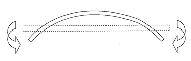
その際に、一般的に、金属帯の反りは、図10のような、金属帯の幅方向に反ったC反りと呼ばれる形状の場合が多く、また金属帯の振動は、金属帯を長手方向から見て、図11(a)に示す曲げモード(弦振動)と図11(b)に示す捩れモードの組み合わせの場合が多いことから、電磁石は金属帯の板幅方向中央部と両エッジ部の3個所に設置することが望まれる。
一方、金属帯の製造ラインでは、通常、一つのラインで様々な板幅の製品を製造している。例えば、ある溶融亜鉛めっき鋼帯の製造ラインでは、板幅が500~1850mmの範囲の製品を製造している。
このような様々な板幅の金属帯に対応するため、金属帯の板幅方向に複数の電磁石を並べ、金属帯の板幅に応じて使用する電磁石を電気的に切り替える技術が提案されている(特許文献2参照)。
この技術によれば、金属帯の板幅変化に対して磁力を発生する範囲を電気的に即座に切り替えることができるため、金属帯の板幅が変化しても、金属帯の反りや振動を効果的に抑制することができるとされている。
金属帯の連続製造ラインにおいては、先行金属帯の尾端と後行金属帯の先端とを溶接により接合することで、金属帯を連続的に通板する。
よって、先行金属帯の板幅と後行金属帯の板幅が異なる場合には、先行金属帯と後行金属帯の接合部で板幅方向に段差(difference in level)が生じる。そこで、製造ラインによっては、その段差部分から金属帯が破断するのを防止するために、接合部の板幅方向両エッジ部を含むように、円弧状等の切欠きを形成するノッチングを行う場合がある。
いずれにせよ、二つの金属帯(先行金属帯と後行金属帯)間の接合部では、同一金属帯内の定常部に比べて板幅方向両エッジ部の剛性が変化し、電磁石の吸引力に対する金属帯の変形度合いが変化する。
よって、特許文献1、2に記載の技術を用いて、二つの金属帯間の接合部を同一金属帯内の定常部と同様に制御しようとしても、安定的に制御することができず、金属帯が電磁石に接触する危険性がある。
本発明は、上記問題に鑑みてなされたものであって、その目的は、金属帯間の接合部においても、金属帯の通過位置(パスライン)を安定的に制御することができる金属帯の安定装置およびそれを用いた溶融めっき金属帯の製造方法を提供することである。
本発明者らは上記課題を解決すべく鋭意検討を重ねた。その結果、金属帯の通過位置(パスライン)を制御する金属帯の安定装置において、金属帯間の接合部が通過する場合に、使用する電磁石を選択的に切り替えることで、安定的に制御を続けることができることを見出した。
本発明は上記知見に基づきなされたものであり、その要旨は以下のとおりである。
[1]複数の金属帯を接合して連続的に通板する金属帯の製造ラインに設置され、ライン内を走行中の金属帯の位置を金属帯板幅方向に並べられた電磁石を用いて非接触で制御する金属帯の安定装置であって、
前記金属帯の位置を非接触で測定する変位センサと、
前記金属帯の接合部前後の板幅情報に基づき電磁石選択を行う電磁石選択装置と、
電磁石選択を行うタイミングを取得し電磁石選択装置に指示する接合部位置情報入力手段と、
少なくとも変位センサの情報と選択された電磁石の情報に基づき、選択された電磁石に流す電流を決定する操作量演算装置とを有し、
金属帯間の接合部が通過する場合に、先行金属帯の板幅と後行金属帯の板幅の狭いほうの板幅よりも狭い範囲内に並べられた電磁石のみから選択的に使用して制御する金属帯の安定装置。
前記金属帯の位置を非接触で測定する変位センサと、
前記金属帯の接合部前後の板幅情報に基づき電磁石選択を行う電磁石選択装置と、
電磁石選択を行うタイミングを取得し電磁石選択装置に指示する接合部位置情報入力手段と、
少なくとも変位センサの情報と選択された電磁石の情報に基づき、選択された電磁石に流す電流を決定する操作量演算装置とを有し、
金属帯間の接合部が通過する場合に、先行金属帯の板幅と後行金属帯の板幅の狭いほうの板幅よりも狭い範囲内に並べられた電磁石のみから選択的に使用して制御する金属帯の安定装置。
[2]前記金属帯の定常部の板幅情報と、当該製造ラインで通板される一連の金属帯の最小板幅の情報に基づき電磁石選択を行う電磁石選択装置とを有し、
金属帯間の接合部が通過する場合に、当該製造ラインで通板される一連の金属帯の最小板幅よりも狭い範囲内に並べられた電磁石のみから選択的に使用して制御する前記[1]に記載の金属帯の安定装置。
金属帯間の接合部が通過する場合に、当該製造ラインで通板される一連の金属帯の最小板幅よりも狭い範囲内に並べられた電磁石のみから選択的に使用して制御する前記[1]に記載の金属帯の安定装置。
[3]製造ラインを通板中の金属帯に溶融金属を付着させる付着工程と、前記金属帯に付着した過剰の溶融金属を払拭するガスワイパによって溶融金属の付着量を調整する調整工程と、前記[1]または[2]に記載の金属帯の安定装置により、前記金属帯の位置を非接触で制御する制御工程とを有する溶融めっき金属帯の製造方法。
本発明によれば、金属帯間の接合部においても、金属帯の通過位置(パスライン)を安定的に制御することができる。
本発明の実施形態について、図面を参照して説明する。なお、ここでは、金属帯として磁性金属帯(鋼帯等)を対象にしている。
[実施形態1]
本発明の実施形態1に係る金属帯の安定装置について説明する。
本発明の実施形態1に係る金属帯の安定装置について説明する。
図1は、本発明の実施形態1に係る金属帯の安定装置1の構成を示す図である。金属帯の安定装置1は、図1中の上方に向かって移動する金属帯2の板幅方向に配された非接触変位センサ3、この非接触変位センサ3からの信号を受けて制御信号を出力する制御部4、制御部4からの制御信号によって金属帯の位置を制御する複数の電磁石5で構成されている。
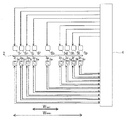
図2は、金属帯2の通板方向から見た電磁石5の配置を示す図である。ここで、Wminは、この金属帯の安定装置1が設置される金属帯の製造ラインで通板される金属帯の最小板幅を示し、Wmaxは最大板幅を示している。
なお、最大板幅Wmaxと最小板幅Wminは、それぞれ、当該金属帯の製造ラインにおける計画休止から計画休止までの間に連続的に通板される金属帯の最大板幅と最小板幅であり、最大板幅Wmaxと最小板幅Wminの比は4以下としている。
電磁石5は、最小板幅Wminの中央部と両エッジ部の3個所に、金属帯2を挟むように対向して配置されている(図2では、5a-5b、5c-5d、5e-5fの3対)。さらに、最小板幅よりも広く、最大板幅よりも狭い範囲に、金属帯2を挟むように対向して複数対の電磁石が配置されている(図2では、5g-5h、5i-5j、5k-5l、5m-5n、5o-5p、5q-5rの6対)。
非接触変位センサ3は、それぞれの電磁石対の近傍の金属帯2片面側に配置されている(図2では、3a、3b、3c、3d、3e、3f、3g、3h、3iの9個)。これは、金属帯2の両面側から距離を測定すると、金属帯2との距離が一意に求まらず、電流の大きさを決定することが難しくなり、結果として電磁石5の制御に支障をきたすからである。
また、非接触変位センサ3は、金属帯2との距離を適切に測定できれば、渦電流式、レーザーなどの光学式など、任意の方式のものが使用できる。
なお、非接触変位センサ3は、図2に示すように、それぞれの電磁石対に1個設置するほうが、制御が容易になる。ただし、電磁石対の数と異なる数の非接触変位センサ3を設置してもよい。例えば、1個の非接触変位センサ3で測定した距離をもとに複数対の電磁石を制御してもよいし、逆に複数の非接触変位センサ3で測定した距離をもとに1対の電磁石を制御するようにしてもよい。
ここで、まず、従来の金属帯の安定装置における制御部4Xについて述べる。
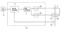
図3は、従来の金属帯の安定装置における制御部4Xの構成を示すブロック図である。ここでは、板幅方向中央部の電磁石対5a、5bの制御のみについて示しているが、他の電磁石対の制御も同様である。
図3に示されるように、従来の金属帯の安定装置の制御部4Xは、操作量演算装置6と、表裏分配装置7と、アンプ8a、8bとを備えている。
操作量演算装置6は、非接触変位センサ3aによる金属帯2の変位の測定値と入力手段9により入力・設定された目標値との偏差信号(difference signal)に対して、比例、微分、積分などの処理(例えばPID制御)(Proportional-Integral-Derivative Controller)を実施して、金属帯2の位置を制御するための制御信号を出力する。
表裏分配装置7は、操作量演算装置6により演算された制御信号を、金属帯2の表面用の電磁石5aおよび裏面用の電磁石5bに分配する。
アンプ8aは、表裏分配装置7により分配された表面用の制御信号に従い、電磁石5aに電流を流し、アンプ8bは、表裏分配装置7により分配された裏面用の制御信号に従い、電磁石5bに電流を流す。以上のように、電磁石5aまたは5bに電流が流されることで吸引力が発生して、金属帯2の反りおよび/または振動を抑制して、金属帯2の通過位置の制御が行われる。
ここで、電磁石5の吸引力で金属帯2を移動させる場合、金属帯2には図4に示すような力が作用する。図4中、A、B、Cは電磁石5aの吸引力を、Dは金属帯2の復元力(restoring force)をそれぞれ示す。なお、図4では、図3における非接触変位センサ3aからみて、金属帯2が離れていく方向に移動したために、電磁石5aを使用して金属帯2を目標位置に引き寄せる場合を示す。
図4において、金属帯2は電磁石5aの吸引力により電磁石5aの方に移動するが、電磁石5aの吸引力は、金属帯2が電磁石5aに近づくほど大きくなり、電磁石5aに流れる電流が大きくなるほど大きくなる。すなわち、電磁石5aに供給される電流が大きくなるにつれて、図4のA→B→Cのように吸引力が大きくなる。
一方、金属帯2には、金属帯2の剛性および通板方向の張力により、電磁石5aの吸引力により移動する前の位置に戻ろうとする復元力が金属帯2の移動量に比例して作用する。復元力は電磁石5aによる金属帯2の移動方向とは反対の方向、すなわち電磁石5aの吸引力とは反対の方向に作用する。電磁石5aの吸引力と金属帯2の復元力がつり合ったところで金属帯2の移動は停止し、このつり合い点で金属帯2は安定する。
非接触変位センサ3aで測定した金属帯2の位置と目標位置までとの距離の差に応じて電磁石5aへ電流を流し、フィードバック制御によって金属帯2が目標位置に達するまで電磁石5aに電流供給する電流を徐々に大きくしながら、金属帯2を目標位置に移動させる。フィードバック制御には、PID制御などの制御方法を適宜使用することができる。
このつり合い点において、金属帯2が電磁石5aに近づく方向に移動した場合は、金属帯2の復元力が大きくなり、金属帯2はつり合い点に戻ろうとし、金属帯2が電磁石5aから遠ざかる方向に移動した場合は、電磁石5aの吸引力が大きくなり、金属帯2はつり合い点に戻ろうとする。つまり、このつり合い点において金属帯2を安定的に保持することが可能となる。
しかし、前述したように、先行金属帯と後行金属帯の間の接合部では、板幅方向エッジ部において板幅変化による段差や円弧状等の切欠きが存在する等のために、金属帯の剛性が部分的に低下し、また、通板方向の張力が不均一になり、金属帯2の復元力と電磁石5aの吸引力が目標位置でつり合わない場合がある。
例えば、図5に示すように、金属帯2の復元力が小さい条件の場合、フィードバック制御により電磁石5aへ供給する電流を大きくしていくと、ある電流値を超えたところで復元力と吸引力とのつり合い点が存在しない状態になる。そのため、金属帯2を安定させることができなくなり、金属帯2がそのまま電磁石5aまで吸引され、接触してしまう危険性がある。それを回避するために、電磁石5aへの電流供給を停止すれば、金属帯2はその復元力によって元の位置に戻り、電磁石5aへの接触は防げるが、溶融金属の付着量が不均一になってしまう。
金属帯の移動にあわせて電磁石に流す電流を追随させる制御が理想であるが、電磁石の応答速度には限界があり、速い制御はできないため、目標位置で金属帯の復元力と電磁石の吸引力のつり合い点が存在しない不安定な状態では、電磁石を用いた制御は困難である。
そこで、この実施形態1では、金属帯間の接合部において、板幅方向エッジ部の形状変化(板幅変化による段差、円弧状等の切欠き)の影響のない領域の電磁石から選択した電磁石のみを用いて制御を行うことで、安定的に制御を行う。
ここで、先行金属帯2aと後行金属帯2bとが接合部10によりつなぎ合わされて連続的に通板される場合について、図6を参照して説明する。
図6において、先行金属帯2aは板幅がWaであり、板幅方向中央部の電磁石5a-5b、および板幅方向エッジ部の電磁石5k-5l、5m-5nの3個所の電磁石対で制御するのが望ましく、後行金属帯2bは板幅がWaより狭いWbであり、板幅方向中央部の電磁石5a-5b、および板幅方向エッジ部の電磁石5g-5h、5i-5jの3個所の電磁石対で制御するのが望ましい。
一方、先行金属帯2aと後行金属帯2bの接合部10の板幅方向エッジ部については、板幅変化による段差があるため、どの電磁石を用いるかが重要になる。
そこで、この実施形態1では、制御部4Aが接合部10の位置情報を受け取り、接合部10が金属帯の安定装置1を通過するタイミングで、板幅方向エッジ部の形状変化の影響のない領域に位置する電磁石で制御するように、電磁石5を選択して使用する。例えば、板幅方向中央部の電磁石5a-5b、および板幅方向エッジ部の電磁石5g-5h、5i-5jの3個所の電磁石対で制御するように、電磁石5を選択して使用する。
このように、先行金属帯2aの板幅と後行金属帯2bの板幅の狭いほうの板幅よりも狭い範囲内に位置する電磁石を用いれば、板幅方向エッジ部の形状変化の影響を受けずに安定的に制御を行うことができる。
なお、接合部10が金属帯の安定装置1を通過するタイミングで、最小板幅Wminよりも狭い領域に位置する電磁石から選択した電磁石のみで制御するように、電磁石5を選択して使用してもよい。すなわち、ここでは、板幅方向中央部の電磁石5a-5b、および板幅方向エッジ部よりも中央部側の電磁石5c-5d、5e-5fの3個所の電磁石対で制御するように、電磁石5を選択して使用してもよい。
その際、先行金属帯2aと後行金属帯2bのどちらも最小板幅Wminより広い場合については、金属帯2を制御する位置が板幅方向エッジ部から遠くなるため、金属帯2の反りや振動の抑制能力は若干低下するが、板幅方向エッジ部の形状変化の影響を受けずに安定的に制御を行うという基本的な制御は可能であり、金属帯2の板幅によらずに、電磁石5を切り替えるため、制御が容易になるというメリットがある。
接合部10において電磁石5を選択的に切り替えるタイミングは、先行金属帯2aと後行金属帯2bの接合部10における段差寸法やノッチング寸法に基づいて適宜設定すればよい。先行金属帯2aと後行金属帯2bの接合部10の段差寸法やノッチング寸法が大きい場合には、金属帯の剛性が変化する範囲が大きくなるため、電磁石5を選択的に使用する範囲も大きくする必要があり、接合部10が金属帯の安定装置1を通過する前から使用する電磁石を切り替え、通過後もある一定範囲継続する必要がある。ただし、先行金属帯2aと後行金属帯2bの接合部10における段差寸法やノッチング寸法が大きい場合でも、接合部10から制御位置が長手方向に最小板幅の長さよりも離れれば金属帯の剛性が変化する範囲を外れ、形状変化の影響を受けずに安定的に制御を行うことは可能であるため、電磁石5を選択的に切り替えるタイミングとして、接合部10が金属帯の安定装置1を通過する前後の長さが最小板幅以上になるように設定すると常に安定的に制御が可能である。
なお、接合部10の位置情報は、製造ラインの操業情報を上位の制御部から受け取っても良いし、別途設置した接合部の検出器等から受け取ってもよい。
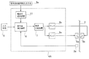
図7は、本発明の実施形態1における制御部4Aのブロック図である。ここでは、板幅方向中央部の電磁石5a、5bの制御のみについて示しているが、他の電磁石対の制御も同様である。
図7に示されるように、本発明の実施形態1における制御部4Aは、操作量演算装置6と、表裏分配装置7と、アンプ8a、8bと、電磁石選択装置11とを備えている。
非接触変位センサ3aによる金属帯2の変位の測定値と入力手段9により入力・設定された目標値との偏差信号により操作量を演算するのは、上述した従来の制御部4Xと同様であるが、接合部位置情報入力手段9aからの接合部10の位置情報に基づいて電磁石選択装置11により電磁石5a、5bの使用有無を判断した上で、電磁石5aまたは電磁石5bを使用する場合のみ制御信号を出力して、金属帯2の通過位置の制御を行う。
なお、ここでは、説明の都合上、電磁石5a、5bを例にしたが、実際には、電磁石5a、5bは常に使用されることになり、実質的に使用有無が判断されるのは、電磁石5c~5rということになる。
このように、この実施形態1においては、制御部4Aが、接合部10前後の板幅情報に基づき電磁石選択を行う電磁石選択装置11と、少なくとも非接触変位センサ3の情報と電磁石選択装置11により選択された電磁石の情報に基づき、選択された電磁石に流す電流値を決定する操作量演算装置6と、操作量演算装置6により演算された電流値の制御信号を金属帯2の表面用の電磁石および裏面用の電磁石に分配する表裏分配装置7と、表裏分配装置7により分配された表面用の制御信号に従い、表面用の電磁石に電流を流すアンプ8aと、表裏分配装置7により分配された裏面用の制御信号に従い、裏面用の電磁石に電流を流すアンプ8bを備えている。
なお、上述したように、接合部10が金属帯の安定装置1を通過するタイミングで、最小板幅Wminよりも狭い領域に位置する電磁石から選択した電磁石のみで制御する場合は、電磁石選択装置11は、その際に使用する電磁石を最小板幅の情報に基づいて選択することになる。
そして、制御部4Aへの入力手段として、金属帯2の変位を測定し、その測定値を電磁石選択装置11に入力する非接触変位センサ3と、金属帯2の変位の目標値を作量演算装置6に入力する入力手段9と、接合部10対応の電磁石選択を行うタイミングを取得し、接合部10の位置情報を電磁石選択装置11に入力する接合部位置情報入力手段9aを備えている。
このような実施形態1によって、金属帯間の接合部10においても、板幅方向エッジ部の形状変化の影響を受けずに、金属帯2と電磁石5が接触することなく、金属帯の通過位置を安定的に制御することが可能となる。
[実施形態2]
本発明の実施形態2として、上記の本発明の実施形態1に係る金属帯の安定装置1を溶融めっき金属帯の製造ラインに配置する際の構成例について説明する。
本発明の実施形態2として、上記の本発明の実施形態1に係る金属帯の安定装置1を溶融めっき金属帯の製造ラインに配置する際の構成例について説明する。
図8は、一般的な溶融めっき金属帯の製造ラインの一部を示す概略図である。
図8に示される溶融めっき金属帯の製造ラインにおいて、金属帯2は、冷間圧延プロセスなどの前工程から運搬され、無酸化性あるいは還元性の雰囲気に保たれた焼鈍炉12において焼鈍処理をされた後、溶融金属の温度とほぼ同程度まで冷却されて、溶融金属浴13内に導かれる。
溶融金属浴13内において、金属帯2は、溶融金属中を浸漬しながら通板し、その表面に溶融金属が付着する。その後、溶融金属浴13から引き出された金属帯2は、ガスワイパ14から噴出されるガスにより過剰な溶融金属が払拭され、溶融金属の付着量の調整が行われる。
その後、用途に応じて、例えばその金属帯2が自動車用外板(automotive exterior panels)として使用される場合には、合金化炉(alloying furnace)15を使用して金属帯2を再加熱し、均質な合金層を作り出す合金化処理を施す場合がある。
そして、金属帯2は冷却帯16を通過した後、化成処理部17で特殊な防錆、耐食処理が施され、コイルに巻き取られて、溶融めっき金属帯2Aとして出荷される。
図9は、溶融めっき金属帯の製造ラインのガスワイパ14の近傍(図8中の破線領域)の拡大図である。
図9に示されるように、溶融めっき金属帯の製造ラインのガスワイパ14の近傍では、引き込みローラー(drawing roller)18が金属帯2を溶融金属浴13中に引き込み、溶融金属浴13中で金属帯2に溶融金属を付着させ、引き上げローラー(pull-up roller)19が金属帯2を溶融金属浴13外に引き上げる。ガスワイパ14は、引き上げローラー19が金属帯2を引き上げる途中のパスラインに配置され、金属帯2に付着した過剰の溶融金属を払拭することによって溶融金属の付着量を調整する。
本発明の実施形態1に係る金属帯の安定装置1の電磁石5および非接触変位センサ3は、ガスワイパ14の直上のパスラインに配置され、すなわち、ガスワイパ14のワイピング時に金属帯2が安定するように常識的な範囲でガスワイパ14に近接して配置され(2m以内が好ましい)、金属帯2の反りおよび/または振動を抑制して、金属帯2の通過位置を制御する。当該配置により、ガスワイパ14と金属帯2との距離が一定となる結果、ワイピングガスの圧力が均一になり、金属帯2に対する溶融金属の付着量のムラを抑えることができる。
なお、本発明の実施形態2として、溶融めっき金属帯の製造ラインを例に説明したが、電磁石を使用して金属帯の位置制御を行う製造ラインであれば、本発明による制御を適用することができることは言うまでもない。
また、金属帯2の通板方向も、鉛直方向に限らず水平方向であってもよい。
以上、本発明を実施形態1、2に基づいて説明したが、本発明は、上記の実施形態1、2による本発明の開示の一部をなす記述及び図面により限定されることはない。
本発明は、金属帯を製造するラインに有用であり、特に溶融めっき金属帯の製造ラインに適している。
1 金属帯の安定装置
2 金属帯
2A 溶融めっき金属帯
3 非接触変位センサ
4 制御部
4A 制御部
4X 制御部
5 電磁石
6 操作量演算装置
7 表裏分配装置
8 アンプ
9 入力手段
9a 接合部位置情報入力手段
10 接合部
11 電磁石選択装置
12 焼鈍炉
13 溶融金属浴
14 ガスワイパ
15 合金化炉
16 冷却帯
17 化成処理部
18 引き込みローラー
19 引き上げローラー
2 金属帯
2A 溶融めっき金属帯
3 非接触変位センサ
4 制御部
4A 制御部
4X 制御部
5 電磁石
6 操作量演算装置
7 表裏分配装置
8 アンプ
9 入力手段
9a 接合部位置情報入力手段
10 接合部
11 電磁石選択装置
12 焼鈍炉
13 溶融金属浴
14 ガスワイパ
15 合金化炉
16 冷却帯
17 化成処理部
18 引き込みローラー
19 引き上げローラー
Claims (3)
- 複数の金属帯を接合して連続的に通板する金属帯の製造ラインに設置され、ライン内を走行中の金属帯の位置を金属帯板幅方向に並べられた電磁石を用いて非接触で制御する金属帯の安定装置であって、
前記金属帯の位置を非接触で測定する変位センサと、
前記金属帯の接合部前後の板幅情報に基づき電磁石選択を行う電磁石選択装置と、
電磁石選択を行うタイミングを取得し電磁石選択装置に指示する接合部位置情報入力手段と、
少なくとも変位センサの情報と選択された電磁石の情報に基づき、選択された電磁石に流す電流を決定する操作量演算装置とを有し、
金属帯間の接合部が通過する場合に、先行金属帯の板幅と後行金属帯の板幅の狭いほうの板幅よりも狭い範囲内に並べられた電磁石のみから選択的に使用して制御する金属帯の安定装置。 - 前記金属帯の定常部の板幅情報と、当該製造ラインで通板される一連の金属帯の最小板幅の情報に基づき電磁石選択を行う電磁石選択装置とを有し、
金属帯間の接合部が通過する場合に、当該製造ラインで通板される一連の金属帯の最小板幅よりも狭い範囲内に並べられた電磁石のみから選択的に使用して制御する請求項1に記載の金属帯の安定装置。 - 製造ラインを通板中の金属帯に溶融金属を付着させる付着工程と、前記金属帯に付着した過剰の溶融金属を払拭するガスワイパによって溶融金属の付着量を調整する調整工程と、請求項1または2に記載の金属帯の安定装置により、前記金属帯の位置および/または振動を非接触で制御する制御工程とを有する溶融めっき金属帯の製造方法。
Priority Applications (1)
| Application Number | Priority Date | Filing Date | Title |
|---|---|---|---|
| JP2016502544A JPWO2016092736A1 (ja) | 2014-12-12 | 2015-10-29 | 金属帯の安定装置および溶融めっき金属帯の製造方法 |
Applications Claiming Priority (2)
| Application Number | Priority Date | Filing Date | Title |
|---|---|---|---|
| JPPCT/JP2014/006203 | 2014-12-12 | ||
| PCT/JP2014/006203 WO2016092601A1 (ja) | 2014-12-12 | 2014-12-12 | 金属帯の安定装置および溶融めっき金属帯の製造方法 |
Publications (1)
| Publication Number | Publication Date |
|---|---|
| WO2016092736A1 true WO2016092736A1 (ja) | 2016-06-16 |
Family
ID=56106855
Family Applications (2)
| Application Number | Title | Priority Date | Filing Date |
|---|---|---|---|
| PCT/JP2014/006203 Ceased WO2016092601A1 (ja) | 2014-12-12 | 2014-12-12 | 金属帯の安定装置および溶融めっき金属帯の製造方法 |
| PCT/JP2015/005436 Ceased WO2016092736A1 (ja) | 2014-12-12 | 2015-10-29 | 金属帯の安定装置および溶融めっき金属帯の製造方法 |
Family Applications Before (1)
| Application Number | Title | Priority Date | Filing Date |
|---|---|---|---|
| PCT/JP2014/006203 Ceased WO2016092601A1 (ja) | 2014-12-12 | 2014-12-12 | 金属帯の安定装置および溶融めっき金属帯の製造方法 |
Country Status (2)
| Country | Link |
|---|---|
| JP (1) | JPWO2016092736A1 (ja) |
| WO (2) | WO2016092601A1 (ja) |
Citations (2)
| Publication number | Priority date | Publication date | Assignee | Title |
|---|---|---|---|---|
| JP2009179834A (ja) * | 2008-01-30 | 2009-08-13 | Mitsubishi-Hitachi Metals Machinery Inc | 帯板の形状矯正・制振方法及び溶融金属めっき鋼板の製造方法 |
| JP2014201798A (ja) * | 2013-04-05 | 2014-10-27 | Jfeスチール株式会社 | 溶融亜鉛めっき鋼帯の製造方法 |
Family Cites Families (1)
| Publication number | Priority date | Publication date | Assignee | Title |
|---|---|---|---|---|
| JP2004091831A (ja) * | 2002-08-30 | 2004-03-25 | Jfe Steel Kk | 溶融めっき金属帯の製造装置及び製造方法 |
-
2014
- 2014-12-12 WO PCT/JP2014/006203 patent/WO2016092601A1/ja not_active Ceased
-
2015
- 2015-10-29 WO PCT/JP2015/005436 patent/WO2016092736A1/ja not_active Ceased
- 2015-10-29 JP JP2016502544A patent/JPWO2016092736A1/ja active Pending
Patent Citations (2)
| Publication number | Priority date | Publication date | Assignee | Title |
|---|---|---|---|---|
| JP2009179834A (ja) * | 2008-01-30 | 2009-08-13 | Mitsubishi-Hitachi Metals Machinery Inc | 帯板の形状矯正・制振方法及び溶融金属めっき鋼板の製造方法 |
| JP2014201798A (ja) * | 2013-04-05 | 2014-10-27 | Jfeスチール株式会社 | 溶融亜鉛めっき鋼帯の製造方法 |
Also Published As
| Publication number | Publication date |
|---|---|
| WO2016092601A1 (ja) | 2016-06-16 |
| JPWO2016092736A1 (ja) | 2017-04-27 |
Similar Documents
| Publication | Publication Date | Title |
|---|---|---|
| US20090191360A1 (en) | Strip crossbow reduction and strip vibration reduction method and hot dip coated strip manufacturing method using the strip stabilization method | |
| JP5979323B1 (ja) | 金属帯の安定装置およびこれを用いた溶融めっき金属帯の製造方法 | |
| KR20200058465A (ko) | 금속판의 형상 계측 장치, 판 휘어짐 교정 장치 및 연속 도금 처리 설비 그리고 금속판의 판 휘어짐 교정 방법 | |
| JP5444706B2 (ja) | 金属帯の制御方法及び溶融めっき金属帯の製造方法 | |
| WO2016092736A1 (ja) | 金属帯の安定装置および溶融めっき金属帯の製造方法 | |
| JP5842855B2 (ja) | 溶融亜鉛めっき鋼帯の製造方法 | |
| JP5644141B2 (ja) | 金属帯の制振及び位置矯正装置、および該装置を用いた溶融めっき金属帯製造方法 | |
| JP5263433B2 (ja) | 金属帯の安定装置および溶融めっき金属帯の製造方法 | |
| JP6274279B2 (ja) | 鋼板の通板位置制御装置および方法 | |
| JP6381858B1 (ja) | 金属板の板反り矯正装置及び金属板の連続めっき処理設備 | |
| JPH1060614A (ja) | 電磁力を利用しためっき付着量調整方法及び装置 | |
| JP4525105B2 (ja) | 金属帯の制御装置および溶融めっき金属帯の製造方法 | |
| JP5223451B2 (ja) | 溶融めっき金属帯の製造方法 | |
| JP6187577B2 (ja) | 金属帯の安定装置および溶融めっき金属帯の製造方法 | |
| JP6648650B2 (ja) | 金属帯の安定装置および溶融めっき金属帯の製造方法 | |
| JP3482024B2 (ja) | 鋼板の形状制御及び制振装置 | |
| JP2004124191A (ja) | 金属帯の制振装置及び金属帯の製造方法 | |
| JP5169089B2 (ja) | 連続溶融金属めっき方法 | |
| JP4450662B2 (ja) | 鋼板の制振装置 | |
| JP6112040B2 (ja) | 金属帯の非接触制御装置および溶融めっき金属帯の製造方法 | |
| JPH07277559A (ja) | 金属帯の支持装置 | |
| WO2000077272A1 (en) | A method and a device for applying a coating onto an elongated object | |
| JP2016151032A (ja) | 溶融金属めっき鋼板の製造設備および製造方法 |
Legal Events
| Date | Code | Title | Description |
|---|---|---|---|
| ENP | Entry into the national phase |
Ref document number: 2016502544 Country of ref document: JP Kind code of ref document: A |
|
| 121 | Ep: the epo has been informed by wipo that ep was designated in this application |
Ref document number: 15867357 Country of ref document: EP Kind code of ref document: A1 |
|
| NENP | Non-entry into the national phase |
Ref country code: DE |
|
| 122 | Ep: pct application non-entry in european phase |
Ref document number: 15867357 Country of ref document: EP Kind code of ref document: A1 |