WO2016092729A1 - 車両用空調装置 - Google Patents
車両用空調装置 Download PDFInfo
- Publication number
- WO2016092729A1 WO2016092729A1 PCT/JP2015/005257 JP2015005257W WO2016092729A1 WO 2016092729 A1 WO2016092729 A1 WO 2016092729A1 JP 2015005257 W JP2015005257 W JP 2015005257W WO 2016092729 A1 WO2016092729 A1 WO 2016092729A1
- Authority
- WO
- WIPO (PCT)
- Prior art keywords
- cooling water
- vehicle
- heat
- casing
- air
- Prior art date
- Legal status (The legal status is an assumption and is not a legal conclusion. Google has not performed a legal analysis and makes no representation as to the accuracy of the status listed.)
- Ceased
Links
Images






Classifications
-
- B—PERFORMING OPERATIONS; TRANSPORTING
- B60—VEHICLES IN GENERAL
- B60H—ARRANGEMENTS OF HEATING, COOLING, VENTILATING OR OTHER AIR-TREATING DEVICES SPECIALLY ADAPTED FOR PASSENGER OR GOODS SPACES OF VEHICLES
- B60H1/00—Heating, cooling or ventilating devices
-
- B—PERFORMING OPERATIONS; TRANSPORTING
- B60—VEHICLES IN GENERAL
- B60H—ARRANGEMENTS OF HEATING, COOLING, VENTILATING OR OTHER AIR-TREATING DEVICES SPECIALLY ADAPTED FOR PASSENGER OR GOODS SPACES OF VEHICLES
- B60H1/00—Heating, cooling or ventilating devices
- B60H1/00507—Details, e.g. mounting arrangements, desaeration devices
- B60H1/00514—Details of air conditioning housings
- B60H1/00521—Mounting or fastening of components in housings, e.g. heat exchangers, fans, electronic regulators
-
- B—PERFORMING OPERATIONS; TRANSPORTING
- B60—VEHICLES IN GENERAL
- B60H—ARRANGEMENTS OF HEATING, COOLING, VENTILATING OR OTHER AIR-TREATING DEVICES SPECIALLY ADAPTED FOR PASSENGER OR GOODS SPACES OF VEHICLES
- B60H1/00—Heating, cooling or ventilating devices
- B60H1/00507—Details, e.g. mounting arrangements, desaeration devices
- B60H1/00514—Details of air conditioning housings
-
- B—PERFORMING OPERATIONS; TRANSPORTING
- B60—VEHICLES IN GENERAL
- B60H—ARRANGEMENTS OF HEATING, COOLING, VENTILATING OR OTHER AIR-TREATING DEVICES SPECIALLY ADAPTED FOR PASSENGER OR GOODS SPACES OF VEHICLES
- B60H1/00—Heating, cooling or ventilating devices
- B60H1/32—Cooling devices
-
- B—PERFORMING OPERATIONS; TRANSPORTING
- B60—VEHICLES IN GENERAL
- B60H—ARRANGEMENTS OF HEATING, COOLING, VENTILATING OR OTHER AIR-TREATING DEVICES SPECIALLY ADAPTED FOR PASSENGER OR GOODS SPACES OF VEHICLES
- B60H1/00—Heating, cooling or ventilating devices
- B60H1/32—Cooling devices
- B60H1/3204—Cooling devices using compression
- B60H1/3228—Cooling devices using compression characterised by refrigerant circuit configurations
- B60H1/32284—Cooling devices using compression characterised by refrigerant circuit configurations comprising two or more secondary circuits, e.g. at evaporator and condenser side
-
- B—PERFORMING OPERATIONS; TRANSPORTING
- B60—VEHICLES IN GENERAL
- B60H—ARRANGEMENTS OF HEATING, COOLING, VENTILATING OR OTHER AIR-TREATING DEVICES SPECIALLY ADAPTED FOR PASSENGER OR GOODS SPACES OF VEHICLES
- B60H1/00—Heating, cooling or ventilating devices
- B60H1/32—Cooling devices
- B60H1/3233—Cooling devices characterised by condensed liquid drainage means
- B60H1/32331—Cooling devices characterised by condensed liquid drainage means comprising means for the use of condensed liquid, e.g. for humidification or for improving condenser performance
Definitions
- the present disclosure relates to an air conditioner used for a vehicle.
- Patent Document 1 discloses a refrigerant / coolant heat exchanger that cools and heats a coolant by exchanging heat between the refrigerant and the coolant in the refrigeration cycle, and air by exchanging heat between the coolant and air.
- An air conditioning apparatus for an automobile is provided that includes a coolant / air heat exchanger that cools and heats the vehicle.
- the refrigerant of the refrigeration cycle cools and heats the cabin by cooling and heating the air via the coolant.
- the refrigerant / coolant heat exchanger is disposed in the engine room, and the coolant / air heat exchanger is disposed in the cabin.
- the refrigerant / coolant heat exchanger reduces the buffer space of the engine room (the space that is crushed at the time of a vehicle collision), which may cause the cabin to be compressed when the vehicle collides.
- the air temperature controllability may be impaired. That is, since the coolant has a large heat capacity, it takes time to change the coolant and air to the target temperature, which may impair the air conditioning comfort of the passenger.
- the present disclosure aims to improve both the collision safety and the air temperature controllability.
- a vehicle air conditioner includes a first heat exchanger that exchanges heat between a refrigerant of a refrigeration cycle and a heat medium, and a second that exchanges heat between air blown into the vehicle interior space and the heat medium.
- the first heat exchanger is disposed on the lower side of the casing, and a partition wall that partitions the vehicle interior space and the engine room is interposed between the first heat exchanger and the casing.
- the first heat exchanger since the first heat exchanger is not sandwiched between the engine and the casing in the vehicle front-rear direction, a buffer space at the time of a vehicle collision can be secured between the engine and the casing. For this reason, even if the vehicle collides, the engine can be prevented from pushing the casing into the vehicle interior space, so that it is possible to prevent the vehicle interior space from being pressed and the passengers cannot be sufficiently protected at the time of the vehicle collision.
- the heat medium pipe between the first heat exchanger and the second heat exchanger can be shortened.
- the amount of the heat medium can be reduced, so that the heat capacity of the heat medium can be kept small, and the air temperature controllability can be suppressed from being impaired by the heat capacity of the heat medium.
- collision safety can be improved, and air temperature controllability can be improved at the same time.
- FIG. 3 is a partially enlarged view of FIG. 2. It is explanatory drawing explaining the mounting position of the vehicle air conditioner in 1st Embodiment. It is sectional drawing of the vehicle carrying the vehicle air conditioner in a comparative example. It is explanatory drawing explaining the mounting position of the vehicle air conditioner in a comparative example. It is a graph which shows an example of the time transition of the blowing air temperature in 1st Embodiment. It is sectional drawing of the vehicle carrying the vehicle air conditioner in 2nd Embodiment. It is a partial schematic diagram of the vehicle air conditioner in 2nd Embodiment.
- the vehicle air conditioner 10 shown in FIG. 1 includes a first pump 11, a second pump 12, a chiller 13, a condenser 14, a cooler core 15, a heater core 16 and a radiator 17.
- the first pump 11 and the second pump 12 are electric pumps that suck and discharge cooling water (heat medium).
- the cooling water is a fluid as a heat medium.
- a liquid containing at least ethylene glycol, dimethylpolysiloxane or nanofluid, or an antifreeze liquid is used as the cooling water.
- the chiller 13, the condenser 14, the cooler core 15, the heater core 16, and the radiator 17 are cooling water distribution devices (heat medium distribution devices) through which cooling water flows.
- the chiller 13 and the condenser 14 are refrigerant coolant heat exchangers (first heat exchangers) that exchange heat between the refrigerant of the refrigeration cycle 20 and the coolant.
- the chiller 13 exchanges heat between the low-pressure side refrigerant of the refrigeration cycle 20 and the cooling water, thereby absorbing the heat of the cooling water into the low-pressure side refrigerant and cooling the cooling water (heat exchanger cooling heat exchange). ).
- the condenser 14 is a high-pressure side heat exchanger (heat dissipating device) that radiates heat of the high-pressure side refrigerant to the cooling water by exchanging heat between the high-pressure side refrigerant of the refrigeration cycle 20 and the cooling water.
- heat dissipating device heat dissipating device
- the refrigeration cycle 20 is a vapor compression refrigerator that includes a compressor 21, a condenser 14, a receiver 22, an expansion valve 23, and a chiller 13.
- a chlorofluorocarbon refrigerant is used as the refrigerant, and a subcritical refrigeration cycle in which the high-pressure side refrigerant pressure does not exceed the critical pressure of the refrigerant is configured.
- the compressor 21 is an electric compressor driven by electric power supplied from a battery, or a variable capacity compressor driven by an engine, and sucks, compresses and discharges the refrigerant of the refrigeration cycle 20.
- the condenser 14 is a condenser that condenses the high-pressure side refrigerant by exchanging heat between the high-pressure side refrigerant (gas phase refrigerant) discharged from the compressor 21 and the cooling water.
- the receiver 22 is a gas-liquid separator that separates the gas-liquid two-phase refrigerant that has flowed out of the capacitor 14 into a gas-phase refrigerant and a liquid-phase refrigerant, and causes the separated liquid-phase refrigerant to flow out to the expansion valve 23 side.
- the expansion valve 23 is a decompression device that decompresses and expands the liquid-phase refrigerant that has flowed out of the receiver 22.
- the chiller 13 is an evaporator that evaporates the low-pressure side refrigerant by exchanging heat between the low-pressure side refrigerant decompressed and expanded by the expansion valve 23 and the cooling water.
- the cooler core 15 and the heater core 16 are air cooling water heat exchangers (second heat exchangers) that exchange heat between the air blown into the vehicle interior space and the cooling water.
- the cooler core 15 is an air cooling heat exchanger that cools air by exchanging heat between the cooling water cooled by the chiller 13 and the air blown into the vehicle interior.
- the heater core 16 is an air heating heat exchanger that heats air by exchanging heat between the cooling water heated by the condenser 14 and the air blown into the vehicle interior.
- the radiator 17 is a radiator (heat medium air heat exchanger) that radiates heat of the cooling water to the outside air by exchanging heat between the cooling water and outside air (air outside the passenger compartment).
- the first pump 11, the chiller 13, and the cooler core 15 constitute a first cooling water circuit C1 (first heat medium circuit).
- the cooling water (first heat medium) circulates in the order of the first pump 11, the chiller 13, the cooler core 15, and the first pump 11.
- the second pump 12, the condenser 14 and the heater core 16 constitute a second cooling water circuit C2 (second heat medium circuit).
- the cooling water (second heat medium) circulates in the order of the second pump 12, the condenser 14, the heater core 16, and the second pump 12.
- the radiator 17 is connected to both the first cooling water circuit C1 and the second cooling water circuit C2.
- the radiator 17 is arranged in parallel with the cooler core 15 and the heater core 16 in the flow of cooling water.
- Switching valves 25 and 26 are arranged at the connection between the radiator 17 and the first cooling water circuit C1 and the second cooling water circuit C2.
- the switching valves 25 and 26 are configured such that the radiator 17 is connected to the first cooling water circuit C1 and the cooling water of the first cooling water circuit C1 flows to the radiator 17, and the radiator 17 is connected to the second cooling water circuit C2. The state in which the cooling water of the second cooling water circuit C2 flows to the radiator 17 is switched.
- the 1st on-off valve 27 is arrange
- the first on-off valve 27 opens and closes the cooling water passage on the cooler core 15 side.
- the switching valves 25 and 26 connect the radiator 17 to the first cooling water circuit C1
- the first on-off valve 27 closes the cooling water flow path on the cooler core 15 side, so that the cooling water in the first cooling water circuit C1 is cooled to the cooler core 15 Can be bypassed to flow through the radiator 17.
- the second on-off valve 28 is disposed in the second cooling water circuit C2.
- the second on-off valve 28 opens and closes the cooling water passage on the heater core 16 side.
- the switching valves 25, 26 connect the radiator 17 to the second cooling water circuit C 2
- the second on-off valve 28 closes the cooling water flow path on the heater core 16 side, so that the cooling water in the second cooling water circuit C 2 becomes the heater core 16. Can be bypassed to flow through the radiator 17.
- the operations of the switching valves 25 and 26, the first on-off valve 27, and the second on-off valve 28 are controlled by a control device (not shown).
- a reserve tank 29 is connected to the first cooling water circuit C1 and the second cooling water circuit C2.
- the reserve tank 29 is a cooling water storage unit that stores excess cooling water.
- the reserve tank 29 is connected to the first cooling water circuit C ⁇ b> 1 on the cooling water suction side of the first pump 11.
- the reserve tank 29 is connected to the second cooling water circuit C ⁇ b> 2 on the cooling water suction side of the second pump 12.
- the radiator 17 is disposed at the forefront of the engine room 2 of the vehicle 1.
- the engine room 2 is an engine housing space for housing the engine 3, and is formed on the vehicle front side with respect to the firewall 4.
- the engine 3 is disposed behind the radiator 17.
- the firewall 4 is a partition wall that partitions the engine room 2 and the vehicle interior space 5. Outside air is blown to the radiator 17 by the outdoor blower 18. A traveling wind can be applied to the radiator 17 when the vehicle is traveling.
- An instrument panel 6 (instrument panel) is arranged at the forefront of the vehicle interior space 5.
- An indoor air conditioning unit 30 is disposed inside the instrument panel 6.
- the indoor air conditioning unit 30 has a casing 31.
- the casing 31 forms an outer shell of the indoor air conditioning unit 30 and forms an air passage through which air blown by an indoor blower (not shown) flows.
- the casing 31 is formed of a resin (for example, polypropylene) having a certain degree of elasticity and excellent in strength.
- the indoor blower is an electric blower that drives a centrifugal multiblade fan (sirocco fan) with an electric motor.
- the cooler core 15 and the heater core 16 are accommodated in the casing 31.
- the cooler core 15 and the heater core 16 are arranged in this order in the air flow direction in the air passage in the casing 31.
- an inside / outside air switching box (not shown) is arranged as an inside / outside air switching device for switching between the inside air (vehicle compartment air) and the outside air (vehicle compartment outside air).
- a heater core passage 31 a through which the air after passing the cooler core 15 flows through the heater core 16
- a bypass passage 31 b through which the air after passing through the cooler core 15 bypasses the heater core 16.
- a mixing space 31c is formed on the downstream side of the air flow of the heater core passage 31a and the bypass passage 31b to mix the hot air flowing out of the heater core passage 31a and the cold air flowing out of the bypass passage 31b.
- an air mix door 32 is disposed on the downstream side of the air flow of the cooler core 15 and on the inlet side of the heater core passage 31a and the bypass passage 31b.
- the air mix door 32 is an air volume ratio adjusting device that continuously changes the air volume ratio between the heater core passage 31a and the bypass passage 31b.
- the temperature of the blown air mixed in the mixing space 31c varies depending on the air volume ratio between the air passing through the heater core passage 31a and the air passing through the bypass passage 31b. Therefore, the air mix door 32 constitutes a temperature adjusting unit that adjusts the air temperature in the mixing space 31c (the temperature of the blown air blown into the vehicle interior).
- the air mix door 32 is configured by a so-called cantilever door configured to include a rotary shaft driven by an electric actuator (not shown) and a plate-like door main body connected to the common rotary shaft. Has been.
- the blower outlet 31d is formed in the most downstream part of the air flow of the casing 31.
- the air outlet 31d blows out the air whose temperature is adjusted in the mixing space 31c to the vehicle interior space 5 that is an air-conditioning target space.
- the face air outlet is an upper body side air outlet that blows air-conditioned air toward the upper body of an occupant in the passenger compartment.
- the foot air outlet is a foot air outlet (lower body air outlet) that blows air-conditioned air toward the feet (lower body) of the occupant.
- the defroster air outlet is a window glass side air outlet that blows out conditioned air toward the inner side surface of the vehicle front window glass.
- An air outlet mode door (not shown) is arranged on the upstream side of the air flow of the face air outlet, the foot air outlet, and the defroster air outlet.
- a blower outlet mode door is a blower outlet mode switching device which switches a blower outlet mode by adjusting the opening area of a face blower outlet, a foot blower outlet, and a defroster blower outlet.
- the air outlet mode door is rotated by an electric actuator (not shown).
- the face air outlet In the face mode, the face air outlet is fully opened and air is blown out from the face air outlet toward the upper body of the passengers in the passenger compartment. In the bi-level mode, both the face air outlet and the foot air outlet are opened and air is blown out toward the upper body and feet of the passengers in the passenger compartment.
- the foot outlet In the foot mode, the foot outlet is fully opened and the defroster outlet is opened by a small opening so that air is mainly blown out from the foot outlet.
- the foot outlet and the defroster outlet In the foot defroster mode, the foot outlet and the defroster outlet are opened to the same extent, and air is blown out from both the foot outlet and the defroster outlet.
- the defroster outlet is fully opened and air is blown out from the defroster outlet to the inner surface of the front window glass of the vehicle.
- a drain water discharge port 31e is formed in the lower portion of the cooler core 15 in the casing 31.
- the drain water discharge port 31e is a condensed water discharge unit that discharges the condensed water (drain water) generated in the cooler core 15 to the outside of the vehicle.
- a drain hose (not shown) that guides condensed water to the outside of the vehicle is connected to the drain water discharge port 31e.
- the drain hose is a condensed water discharge hose for discharging condensed water generated in the casing 31 to the outside of the vehicle.
- the fire wall 4 is formed with a protrusion 4 a that swells in a tunnel shape directly below the indoor air-conditioning unit 30 at the center in the vehicle left-right direction.
- the space formed on the lower side of the protrusion 4 a is a vehicle exterior space that communicates with the engine room 2.
- a cooling water circuit unit WU composed of the first pump 11, the second pump 12, the chiller 13, the condenser 14 and the like is disposed in the space outside the passenger compartment (engine room 2) below the protrusion 4a.
- the protrusion 4a is an interposed portion interposed between the indoor air conditioning unit 30 and the cooling water circuit unit WU.
- the cooling water circuit unit WU is disposed in a vehicle exterior space located below the indoor air conditioning unit 30.
- the coolant circuit unit WU is separated from the indoor air conditioning unit 30 by a firewall 4.
- the cooling water circuit unit WU is disposed at a position not sandwiched between the engine 3 and the indoor air conditioning unit 30 in the vehicle longitudinal direction. Thereby, a buffer space 2 a at the time of a vehicle collision is formed between the engine 3 and the indoor air conditioning unit 30.
- the chiller 13 and the capacitor 14 are arranged below the casing 31, and the firewall 4 is interposed between the chiller 13 and the capacitor 14 and the casing 31.
- condenser 14 are arrange
- the coolant circuit unit WU is disposed in the engine room 2 so as to be sandwiched between the engine 3 and the indoor air conditioning unit 30 in the vehicle front-rear direction.
- a sufficient buffer space at the time of a vehicle collision cannot be formed between the engine 3 and the indoor air conditioning unit 30.
- the engine 3 may push the indoor air conditioning unit 30 into the vehicle interior space 5, so that the vehicle interior space 5 may be pressed at the time of the vehicle collision and the passengers may not be sufficiently protected.
- the cooling water circuit unit WU is not sandwiched between the engine 3 and the indoor air conditioning unit 30 in the vehicle front-rear direction, so that the vehicle is interposed between the engine 3 and the indoor air conditioning unit 30.
- the buffer space 2a at the time of collision can be secured (FIG. 2). Therefore, even if the vehicle collides, the engine 3 can be suppressed from pushing the indoor air conditioning unit 30 into the vehicle interior space 5, so that it is possible to suppress the vehicle interior space 5 from being pressed and unable to sufficiently protect the occupant when the vehicle collides. .
- FIG. 7 is a graph showing an example of time transition of the blown air temperature in the present embodiment.
- the dashed-two dotted line in FIG. 7 has shown an example of the time transition of the blowing air temperature in the comparative example shown in FIG. 5, FIG. That is, in this comparative example, since the cooling water circuit unit WU is disposed in the engine room 2 located on the front side of the indoor air conditioning unit 30, the cooling water between the cooling water circuit unit WU and the indoor air conditioning unit 30 is used. The piping becomes longer. For this reason, the amount of cooling water increases and the heat capacity of the cooling water increases, so the air temperature controllability is impaired by the heat capacity of the cooling water.
- the cooling water circuit unit WU is arrange
- the cooling water piping between the cooling water circuit unit WU and the indoor air conditioning unit 30 is shortened. be able to. Therefore, the amount of cooling water can be reduced and the heat capacity of the cooling water can be kept small, so that the air temperature controllability can be prevented from being impaired by the heat capacity of the cooling water.
- the cooling water circuit unit WU (the chiller 13 and the condenser 14) is disposed at the center in the vehicle left-right direction. According to this, the cooling water circuit unit WU is arranged avoiding the front seat occupant when viewed from the front-rear direction of the vehicle, so that collision safety can be improved.
- one end of a drain hose (not shown) is connected to the drain water discharge port 31 e of the casing 31, and the other end of the drain hose is connected to the capacitor 14.
- the condensed water guided to the condenser 14 by the drain hose flows inside or on the surface of the condenser 14. Thereby, at least one of the refrigerant and the cooling water flowing inside the condenser 14 is cooled by the condensed water led to the condenser 14.
- the condenser 14 is disposed at a position where the condensed water generated in the casing 31 falls due to gravity. Thereby, the refrigerant
- At least one of the refrigerant and the cooling water flowing inside the condenser 14 is cooled by the condensed water from the drain water discharge port 31e.
- the drain water is used.
- the condensed water from the discharge port 31e cools the high-pressure side refrigerant of the refrigeration cycle 20 or the cooling water of the second cooling water circuit C2.
- the pipe 41 is in contact with the drain hose 40 so as to conduct heat.
- the high pressure side refrigerant of the refrigeration cycle 20 or the cooling water of the second cooling water circuit C2 flows through the pipe 41.
- the drain hose 40 and the pipe 41 exchange heat between the condensed water refrigerant heat exchange unit that exchanges heat between the condensed water generated in the casing 31 and the refrigerant, or the condensed water generated in the casing 31 and the cooling water (heat medium). It is a condensed water cooling water heat exchange part (3rd heat exchanger) to be made.
- the portion of the pipe 41 that is in contact with the drain hose 40 is formed of a material having a high thermal conductivity such as aluminum.
- the part of the drain hose 40 that is in contact with the pipe 41 is also formed of a high heat conductivity such as aluminum.
- a spiral groove or a spiral projection is formed on the inner wall surface of this part.
- the condensed water which flows inside becomes easy to spread on an inner wall surface.
- heat transfer fins inner fins that promote heat exchange may be formed inside the drain hose 40.
- the drain hose 40 and the pipe 41 are arranged at a position where the condensed water in the casing 31 falls due to gravity. Thereby, a high pressure side refrigerant
- the protrusion 4 a of the firewall 4 is formed so as to be divided with respect to other parts of the firewall 4.
- the protrusion 4a is fixed to another part of the firewall 4 by fastening means such as a bolt 45.
- the indoor air conditioning unit 30 and the cooling water circuit unit WU are fixed to the protrusion 4a by fastening means such as bolts.
- the indoor air conditioning unit 30 and the cooling water circuit unit WU are assembled to the projection 4a, and then the projection 4a is assembled to another part of the firewall 4.
- the protrusion 4a of the firewall 4 is divided and formed with respect to the remaining portion of the firewall 4, and the indoor air conditioning unit 30 (casing 31) and the cooling water circuit unit WU (chiller 13 and The capacitor 14) is fixed to the protrusion 4a.
- the indoor air conditioning unit 30 and the cooling water circuit unit WU can be integrally mounted on the vehicle, the vehicle mounting workability of the indoor air conditioning unit 30 and the cooling water circuit unit WU can be improved.
- the first cooling water discharge hose 46 and the second cooling water discharge hose 47 join the drain hose 40 that discharges condensed water from the casing 31.
- the first cooling water discharge hose 46 is a cooling water discharge hose (heat medium discharge hose) for discharging the cooling water (heat medium) of the first cooling water circuit C1.
- the second cooling water discharge hose 47 is a cooling water discharge hose (heat medium discharge hose) that discharges the cooling water (heat medium) of the second cooling water circuit C2.
- a first discharge valve 48 is disposed in the first cooling water discharge hose 46.
- the first discharge valve 48 opens and closes the cooling water flow path in the first cooling water discharge hose 46.
- the second cooling water discharge hose 47 is provided with a second discharge valve 49.
- the second discharge valve 49 opens and closes the cooling water flow path in the second cooling water discharge hose 47.
- the first cooling water discharge hose 46, the second cooling water discharge hose 47, the first discharge valve 48 and the second discharge valve 49 are supplied from the first cooling water circuit C1 and the second cooling water circuit C2 during maintenance work or the like. Used when discharging.
- first cooling water discharge hose 46 and the second cooling water discharge hose 47 are joined to the drain hose 40.
- FIG. 13 includes the first cooling water circuit C1
- the example of FIG. 14 includes the second cooling water circuit C2.
- a high-pressure side heat exchanger 50 that exchanges heat between the high-pressure side refrigerant of the refrigeration cycle 20 and air is provided instead of the capacitor 14 of the above embodiment. Therefore, the high-pressure side refrigerant discharged from the compressor 21 is cooled by exchanging heat with air.
- a low-pressure side heat exchanger 51 that exchanges heat between the low-pressure side refrigerant of the refrigeration cycle 20 and air is provided.
- cooling water is used as the heat medium flowing through the first cooling water circuit C1 and the second cooling water circuit C2, but various media such as oil may be used as the heat medium.
- heat medium ethylene glycol antifreeze, water, air maintained at a certain temperature or higher may be used.
- Nanofluid may be used as the heat medium.
- a nanofluid is a fluid in which nanoparticles having a particle size of the order of nanometers are mixed.
- antifreeze liquid ethylene glycol
- the effect of improving the thermal conductivity in a specific temperature range the effect of increasing the heat capacity of the heat medium, the effect of preventing the corrosion of metal pipes and the deterioration of rubber pipes, and the heat medium at an extremely low temperature
- liquidity of can be acquired.
- Such an effect varies depending on the particle configuration, particle shape, blending ratio, and additional substance of the nanoparticles.
- the thermal conductivity can be improved, it is possible to obtain the same cooling efficiency even with a small amount of heat medium as compared with the cooling water using ethylene glycol.
- the amount of heat stored in the heat medium itself can be increased.
- the aspect ratio of the nanoparticles is preferably 50 or more. This is because sufficient thermal conductivity can be obtained.
- the aspect ratio is a shape index that represents the ratio of the vertical and horizontal dimensions of the nanoparticles.
- Nanoparticles containing any of Au, Ag, Cu and C can be used. Specifically, Au nanoparticle, Ag nanowire, CNT (carbon nanotube), graphene, graphite core-shell nanoparticle (a structure such as a carbon nanotube surrounding the above atom is included as a constituent atom of the nanoparticle. Particles), Au nanoparticle-containing CNTs, and the like can be used.
- a chlorofluorocarbon refrigerant is used as the refrigerant, but the type of the refrigerant is not limited to this, and natural refrigerant such as carbon dioxide, hydrocarbon refrigerant, or the like is used. May be.
- the refrigeration cycle 20 of the above embodiment constitutes a subcritical refrigeration cycle in which the high-pressure side refrigerant pressure does not exceed the critical pressure of the refrigerant, but the supercritical refrigeration cycle in which the high-pressure side refrigerant pressure exceeds the critical pressure of the refrigerant. You may comprise.
Landscapes
- Engineering & Computer Science (AREA)
- Physics & Mathematics (AREA)
- Thermal Sciences (AREA)
- Mechanical Engineering (AREA)
- Air-Conditioning For Vehicles (AREA)
- Chemical & Material Sciences (AREA)
- Combustion & Propulsion (AREA)
Abstract
車両用空調装置は、冷凍サイクル(20)の冷媒と熱媒体とを熱交換させる第1熱交換器(13、14)と、車室内空間(5)へ送風される空気と熱媒体とを熱交換させる第2熱交換器(15、16)と、車室内空間(5)に配置され、空気が流れる空気通路を形成し、第2熱交換器(15、16)を収容するケーシング(31)とを備える。第1熱交換器(13、14)は、ケーシング(31)の下方側に配置されており、第1熱交換器(13、14)とケーシング(31)との間には、車室内空間(5)とエンジンルーム(2)とを仕切る隔壁(4)が介在している。
Description
本出願は、当該開示内容が参照によって本出願に組み込まれた、2014年12月10日に出願された日本特許出願2014-249628号を基にしている。
本開示は、車両に用いられる空調装置に関する。
従来、特許文献1には、冷凍サイクルの冷媒と冷却剤とを熱交換させることによって冷却剤を冷却・加熱する冷媒/冷却剤熱交換器と、冷却剤と空気とを熱交換させることによって空気を冷却・加熱する冷却剤/空気熱交換器とを備える自動車の冷暖房装置が記載されている。
この従来技術では、冷凍サイクルの冷媒が冷却剤を介して空気を冷却・加熱することによって、キャビンを冷暖房するようになっている。
この従来技術では、冷媒/冷却剤熱交換器がエンジンルーム内に配置され、冷却剤/空気熱交換器がキャビン内に配置されている。
しかしながら、本開示の発明者らの検討によると、上記従来技術では、エンジンルーム内に冷媒/冷却剤熱交換器が配置されることによって衝突安全性が損なわれるおそれがある。すなわち、冷媒/冷却剤熱交換器がエンジンルームの緩衝空間(車両衝突時に潰れる空間)を減少させてしまうので、車両衝突時にキャビンが圧迫されるおそれがある。
また、上記従来技術では、冷凍サイクルの冷媒が冷却剤を介して空気を冷却・加熱するので、空気温度制御性が損なわれるおそれがある。すなわち、冷却剤が大きな熱容量を持つので、冷却剤および空気を狙いの温度に変化させるまでに時間がかかってしまい、乗員の空調快適性が損なわれるおそれがある。
本開示は上記点に鑑みて、衝突安全性を向上することと、空気温度制御性を向上することとを両立することを目的とする。
本開示の一つの態様による車両用空調装置は、冷凍サイクルの冷媒と熱媒体とを熱交換させる第1熱交換器と、車室内空間へ送風される空気と熱媒体とを熱交換させる第2熱交換器と、車室内空間に配置され、空気が流れる空気通路を形成し、第2熱交換器を収容するケーシングとを備える。第1熱交換器は、ケーシングの下方側に配置されており、第1熱交換器とケーシングとの間には、車室内空間とエンジンルームとを仕切る隔壁が介在している。
これによると、第1熱交換器が、車両前後方向においてエンジンとケーシングの間に挟まれないので、エンジンとケーシングとの間に車両衝突時の緩衝空間を確保できる。そのため、車両が衝突してもエンジンがケーシングを車室内空間に押し出すことを抑制できるので、車両衝突時に車室内空間が圧迫されて乗員を十分に保護できなくなることを抑制できる。
また、第1熱交換器がケーシングの下方側に配置されているので、第1熱交換器と第2熱交換器との間の熱媒体配管を短くすることができる。そのため、熱媒体を少量化できるので、熱媒体の熱容量を小さく抑えることができ、ひいては熱媒体の熱容量によって空気温度制御性が損なわれることを抑制できる。
したがって、衝突安全性を向上でき、同時に空気温度制御性を向上できる。
以下、実施形態について図に基づいて説明する。なお、以下の各実施形態相互において、互いに同一もしくは均等である部分には、図中、同一符号を付してある。
(第1実施形態)
以下、第1実施形態を図1~図7に基づいて説明する。図中、上下前後左右の矢印は、車両の上下前後左右方向を示している。
以下、第1実施形態を図1~図7に基づいて説明する。図中、上下前後左右の矢印は、車両の上下前後左右方向を示している。
図1に示す車両用空調装置10は、第1ポンプ11、第2ポンプ12、チラー13、コンデンサ14、クーラコア15、ヒータコア16およびラジエータ17を備えている。
第1ポンプ11および第2ポンプ12は、冷却水(熱媒体)を吸入して吐出する電動ポンプである。冷却水は、熱媒体としての流体である。本実施形態では、冷却水として、少なくともエチレングリコール、ジメチルポリシロキサンもしくはナノ流体を含む液体、または不凍液体が用いられている。
チラー13、コンデンサ14、クーラコア15、ヒータコア16およびラジエータ17は、冷却水が流通する冷却水流通機器(熱媒体流通機器)である。
チラー13およびコンデンサ14は、冷凍サイクル20の冷媒と冷却水とを熱交換させる冷媒冷却水熱交換器(第1熱交換器)である。
チラー13は、冷凍サイクル20の低圧側冷媒と冷却水とを熱交換させることによって冷却水の熱を低圧側冷媒に吸熱させて冷却水を冷却する低圧側熱交換器(熱媒体冷却用熱交換器)である。
コンデンサ14は、冷凍サイクル20の高圧側冷媒と冷却水とを熱交換させることによって高圧側冷媒の熱を冷却水に放熱させる高圧側熱交換器(放熱機器)である。
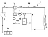
冷凍サイクル20は、圧縮機21、コンデンサ14、レシーバ22、膨張弁23およびチラー13を備える蒸気圧縮式冷凍機である。本実施形態の冷凍サイクル20では、冷媒としてフロン系冷媒を用いており、高圧側冷媒圧力が冷媒の臨界圧力を超えない亜臨界冷凍サイクルを構成している。
圧縮機21は、電池から供給される電力によって駆動される電動圧縮機、またはエンジンによって駆動される可変容量圧縮機であり、冷凍サイクル20の冷媒を吸入して圧縮して吐出する。
コンデンサ14は、圧縮機21から吐出された高圧側冷媒(気相冷媒)と冷却水とを熱交換させることによって高圧側冷媒を凝縮させる凝縮器である。レシーバ22は、コンデンサ14から流出した気液2相冷媒を気相冷媒と液相冷媒とに分離して、分離された液相冷媒を膨張弁23側に流出させる気液分離器である。
膨張弁23は、レシーバ22から流出した液相冷媒を減圧膨張させる減圧装置である。チラー13は、膨張弁23で減圧膨張された低圧側冷媒と冷却水とを熱交換させることによって低圧側冷媒を蒸発させる蒸発器である。
クーラコア15およびヒータコア16は、車室内空間へ送風される空気と冷却水とを熱交換させる空気冷却水熱交換器(第2熱交換器)である。
クーラコア15は、チラー13で冷却された冷却水と、車室内へ送風される空気とを熱交換させることによって空気を冷却する空気冷却用熱交換器である。
ヒータコア16は、コンデンサ14で加熱された冷却水と、車室内へ送風される空気とを熱交換させることによって空気を加熱する空気加熱用熱交換器である。
ラジエータ17は、冷却水と外気(車室外空気)とを熱交換することによって冷却水の熱を外気に放熱させる放熱器(熱媒体空気熱交換器)である。
第1ポンプ11、チラー13およびクーラコア15は、第1冷却水回路C1(第1熱媒体回路)を構成している。第1冷却水回路C1では、冷却水(第1熱媒体)が第1ポンプ11、チラー13、クーラコア15、第1ポンプ11の順に循環する。
第2ポンプ12、コンデンサ14およびヒータコア16は、第2冷却水回路C2(第2熱媒体回路)を構成している。第2冷却水回路C2では、冷却水(第2熱媒体)が第2ポンプ12、コンデンサ14、ヒータコア16、第2ポンプ12の順に循環する。
ラジエータ17は、第1冷却水回路C1および第2冷却水回路C2の両方に接続されている。ラジエータ17は、冷却水の流れにおいて、クーラコア15およびヒータコア16と並列に配置されている。
ラジエータ17と第1冷却水回路C1および第2冷却水回路C2との接続部には、切替弁25、26が配置されている。切替弁25、26は、ラジエータ17が第1冷却水回路C1に接続されてラジエータ17に第1冷却水回路C1の冷却水が流れる状態と、ラジエータ17が第2冷却水回路C2に接続されてラジエータ17に第2冷却水回路C2の冷却水が流れる状態とを切り替える。
第1冷却水回路C1には、第1開閉弁27が配置されている。第1開閉弁27は、クーラコア15側の冷却水流路を開閉する。切替弁25、26がラジエータ17を第1冷却水回路C1に接続したときに第1開閉弁27がクーラコア15側の冷却水流路を閉じることによって、第1冷却水回路C1の冷却水がクーラコア15をバイパスしてラジエータ17を流れるようにすることができる。
第2冷却水回路C2には、第2開閉弁28が配置されている。第2開閉弁28は、ヒータコア16側の冷却水流路を開閉する。切替弁25、26がラジエータ17を第2冷却水回路C2に接続したときに第2開閉弁28がヒータコア16側の冷却水流路を閉じることによって、第2冷却水回路C2の冷却水がヒータコア16をバイパスしてラジエータ17を流れるようにすることができる。
切替弁25、26、第1開閉弁27および第2開閉弁28の作動は、制御装置(図示せず)によって制御される。
第1冷却水回路C1および第2冷却水回路C2にはリザーブタンク29が接続されている。リザーブタンク29は、余剰冷却水を貯留する冷却水貯留部である。リザーブタンク29は、第1ポンプ11の冷却水吸入側において第1冷却水回路C1に接続されている。リザーブタンク29は、第2ポンプ12の冷却水吸入側において第2冷却水回路C2に接続されている。
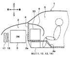
図2に示すように、ラジエータ17は、車両1のエンジンルーム2の最前部に配置されている。エンジンルーム2は、エンジン3を収容するエンジン収容空間であり、ファイヤーウォール4よりも車両前方側に形成されている。
エンジン3は、ラジエータ17の後方に配置されている。ファイヤーウォール4は、エンジンルーム2と車室内空間5とを仕切る隔壁である。ラジエータ17には、室外送風機18によって外気が送風される。車両の走行時にはラジエータ17に走行風を当てることができるようになっている。
車室内空間5の最前部には計器盤6(インストルメントパネル)が配置されている。計器盤6の内側には室内空調ユニット30が配置されている。
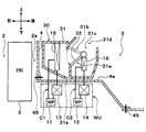
図3に示すように、室内空調ユニット30はケーシング31を有している。ケーシング31は、室内空調ユニット30の外殻を形成しているとともに、室内送風機(図示せず)によって送風された空気が流れる空気通路を形成している。
ケーシング31は、ある程度の弾性を有し、強度的にも優れた樹脂(例えば、ポリプロピレン)にて成形されている。室内送風機は、遠心多翼ファン(シロッコファン)を電動モータにて駆動する電動送風機である。
ケーシング31の内部には、クーラコア15およびヒータコア16が収容されている。クーラコア15およびヒータコア16は、ケーシング31内の空気通路における空気流れ方向にこの順番で配置されている。
ケーシング31内の送風空気流れ最上流側には、内気(車室内空気)と外気(車室外空気)とを切替導入する内外気切替装置としての内外気切替箱(図示せず)が配置されている。
ケーシング31内において、クーラコア15の空気流れ下流側には、クーラコア15通過後の空気がヒータコア16を流れるヒータコア通路31aと、クーラコア15通過後の空気がヒータコア16をバイパスして流れるバイパス通路31bとが並列に形成されている。
ケーシング31内において、ヒータコア通路31aおよびバイパス通路31bの空気流れ下流側には、ヒータコア通路31aから流出した温風とバイパス通路31bから流出した冷風とを混合させる混合空間31cが形成されている。
ケーシング31内において、クーラコア15の空気流れ下流側であって、ヒータコア通路31aおよびバイパス通路31bの入口側には、エアミックスドア32が配置されている。
エアミックスドア32は、ヒータコア通路31aとバイパス通路31bとの風量割合を連続的に変化させる風量割合調整装置である。ヒータコア通路31aを通過する空気とバイパス通路31bを通過する空気との風量割合によって、混合空間31cにて混合された送風空気の温度が変化する。したがって、エアミックスドア32は、混合空間31c内の空気温度(車室内へ送風される送風空気の温度)を調整する温度調整部を構成する。
エアミックスドア32は、電動アクチュエータ(図示せず)によって駆動される回転軸と、その共通の回転軸に連結された板状のドア本体部を有して構成される、いわゆる片持ちドアで構成されている。
ケーシング31の空気流れ最下流部には吹出口31dが形成されている。吹出口31dは、混合空間31cの温度調整された空気を、空調対象空間である車室内空間5へ吹き出す。
吹出口31dとしては、フェイス吹出口、フット吹出口およびデフロスタ吹出口が設けられている。フェイス吹出口は、車室内の乗員の上半身に向けて空調風を吹き出す上半身側吹出口である。フット吹出口は、乗員の足元(下半身)に向けて空調風を吹き出す足元側吹出口(下半身側吹出口)である。デフロスタ吹出口は、車両前面窓ガラス内側面に向けて空調風を吹き出す窓ガラス側吹出口である。
フェイス吹出口、フット吹出口およびデフロスタ吹出口の空気流れ上流側には、吹出口モードドア(図示せず)が配置されている。吹出口モードドアは、フェイス吹出口、フット吹出口およびデフロスタ吹出口の開口面積を調整することによって吹出口モードを切り替える吹出口モード切替装置である。吹出口モードドアは、電動アクチュエータ(図示せず)によって回転操作される。
吹出口モードとしては、フェイスモード、バイレベルモード、フットモード、フットデフロスタモードおよびデフロスタモードがある。
フェイスモードでは、フェイス吹出口を全開してフェイス吹出口から車室内乗員の上半身に向けて空気を吹き出す。バイレベルモードでは、フェイス吹出口とフット吹出口の両方を開口して車室内乗員の上半身と足元に向けて空気を吹き出す。
フットモードでは、フット吹出口を全開するとともにデフロスタ吹出口を小開度だけ開口して、フット吹出口から主に空気を吹き出す。フットデフロスタモードでは、フット吹出口およびデフロスタ吹出口を同程度開口して、フット吹出口およびデフロスタ吹出口の双方から空気を吹き出す。
デフロスタモードでは、デフロスタ吹出口を全開してデフロスタ吹出口から車両前面窓ガラス内面に空気を吹き出す。
ケーシング31のうちクーラコア15の下方側部位には、ドレン水排出口31eが形成されている。ドレン水排出口31eは、クーラコア15で発生した凝縮水(ドレン水)を車外へ排出する凝縮水排出部である。ドレン水排出口31eには、凝縮水を車外へ導くドレンホース(図示せず)が接続されている。ドレンホースは、ケーシング31内で発生した凝縮水を車外へ排出するための凝縮水排出ホースである。
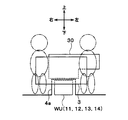
図2、図3、図4に示すように、ファイヤーウォール4には、車両左右方向中央部において室内空調ユニット30の直下に向かってトンネル状に膨らむ突起部4aが形成されている。突起部4aの下方側に形成される空間は、エンジンルーム2と連通する車室外空間である。
突起部4aの下方側における車室外空間(エンジンルーム2)には、第1ポンプ11、第2ポンプ12、チラー13およびコンデンサ14等で構成される冷却水回路ユニットWUが配置されている。突起部4aは、室内空調ユニット30と冷却水回路ユニットWUとの間に介在する介在部である。
冷却水回路ユニットWUは、室内空調ユニット30の下方側に位置する車室外空間に配置されている。冷却水回路ユニットWUは、室内空調ユニット30に対してファイヤーウォール4で隔てられている。
冷却水回路ユニットWUは、車両前後方向においてエンジン3と室内空調ユニット30の間に挟まれない位置に配置されている。これにより、エンジン3と室内空調ユニット30との間に車両衝突時の緩衝空間2aが形成されている。
換言すれば、チラー13およびコンデンサ14は、ケーシング31の下方側に配置されており、チラー13およびコンデンサ14とケーシング31との間にはファイヤーウォール4が介在している。これにより、チラー13およびコンデンサ14は、車両前後方向においてエンジン3とケーシング31との間に挟まれないように車室外空間(エンジンルーム2)に配置されている。
図5、図6に示す比較例では、冷却水回路ユニットWUは、車両前後方向においてエンジン3と室内空調ユニット30の間に挟まれるようにエンジンルーム2に配置されている。この比較例によると、エンジン3と室内空調ユニット30との間に車両衝突時の緩衝空間を十分に形成することができない。そのため、車両が衝突するとエンジン3が室内空調ユニット30を車室内空間5に押し出してしまうおそれがあるので、車両衝突時に車室内空間5が圧迫されて乗員を十分に保護できなくなるおそれがある。
これに対して、本実施形態では、冷却水回路ユニットWUが、車両前後方向においてエンジン3と室内空調ユニット30との間に挟まれていないので、エンジン3と室内空調ユニット30との間に車両衝突時の緩衝空間2aを確保できる(図2)。そのため、車両が衝突してもエンジン3が室内空調ユニット30を車室内空間5に押し出すことを抑制できるので、車両衝突時に車室内空間5が圧迫されて乗員を十分に保護できなくなることを抑制できる。
図7は、本実施形態における吹出空気温度の時間推移の一例を示すグラフである。図7中の二点鎖線は、図5、図6に示す比較例における吹出空気温度の時間推移の一例を示している。すなわち、この比較例では、冷却水回路ユニットWUが室内空調ユニット30の前方側に位置するエンジンルーム2内に配置されているので、冷却水回路ユニットWUと室内空調ユニット30との間の冷却水配管が長くなってしまう。そのため、冷却水の量が多くなり、冷却水の熱容量が大きくなってしまうので、冷却水の熱容量によって空気温度制御性が損なわれてしまう。
これに対して、本実施形態では、冷却水回路ユニットWUが室内空調ユニット30の下方側に配置されているので、冷却水回路ユニットWUと室内空調ユニット30との間の冷却水配管を短くすることができる。そのため、冷却水を少量化して、冷却水の熱容量を小さく抑えることができるので、冷却水の熱容量によって空気温度制御性が損なわれることを抑制できる。
したがって、本実施形態によると、衝突安全性の悪化を抑制することと、空気温度制御性の悪化を抑制することとを両立できる。
本実施形態では、冷却水回路ユニットWU(チラー13およびコンデンサ14)は、車両左右方向の中央部に配置されている。これによると、車両前後方向から見たときに冷却水回路ユニットWUが前席の乗員を避けて配置されることになるので、衝突安全性を向上できる。
(第2実施形態)
本実施形態では、図8、図9に示すように、ケーシング31のドレン水排出口31eから排出された凝縮水がコンデンサ14に導かれるようになっている。図8、図9の太矢印は、凝縮水の流れを模式的に示している。
本実施形態では、図8、図9に示すように、ケーシング31のドレン水排出口31eから排出された凝縮水がコンデンサ14に導かれるようになっている。図8、図9の太矢印は、凝縮水の流れを模式的に示している。
具体的には、ケーシング31のドレン水排出口31eにドレンホース(図示せず)の一端が接続されており、ドレンホースの他端がコンデンサ14に接続されている。ドレンホースによってコンデンサ14に導かれた凝縮水は、コンデンサ14の内部または表面を流れる。これにより、コンデンサ14に導かれた凝縮水によって、コンデンサ14の内部を流れる冷媒および冷却水のうち少なくとも一方が冷却される。
本実施形態では、コンデンサ14は、ケーシング31内で発生した凝縮水が重力で落下する位置に配置されている。これにより、凝縮水を利用してコンデンサ14の冷媒冷却能力を向上できる。
(第3実施形態)
上記第2実施形態では、ドレン水排出口31eからの凝縮水によって、コンデンサ14の内部を流れる冷媒および冷却水のうち少なくとも一方が冷却されるようになっているが、本実施形態では、ドレン水排出口31eからの凝縮水によって、冷凍サイクル20の高圧側冷媒または第2冷却水回路C2の冷却水が冷却されるようになっている。
上記第2実施形態では、ドレン水排出口31eからの凝縮水によって、コンデンサ14の内部を流れる冷媒および冷却水のうち少なくとも一方が冷却されるようになっているが、本実施形態では、ドレン水排出口31eからの凝縮水によって、冷凍サイクル20の高圧側冷媒または第2冷却水回路C2の冷却水が冷却されるようになっている。
具体的には、図10に示すように、ドレンホース40に配管41が熱伝導可能に接触している。配管41には、冷凍サイクル20の高圧側冷媒または第2冷却水回路C2の冷却水が流れる。
ドレンホース40および配管41は、ケーシング31内で発生した凝縮水と冷媒とを熱交換させる凝縮水冷媒熱交換部、またはケーシング31内で発生した凝縮水と冷却水(熱媒体)とを熱交換させる凝縮水冷却水熱交換部(第3熱交換器)である。
配管41のうちドレンホース40と接触している部位は、アルミなどの熱伝導率の高い伝属で形成されている。
ドレンホース40のうち配管41と接触している部位も、アルミなどの熱伝導率の高い伝属で形成されている。この部位の内壁面には螺旋状の溝または螺旋状の突起が形成されている。これにより、内部を流れる凝縮水が内壁面に広がりやすくなる。ドレンホース40の内部に、熱交換を促進する伝熱フィン(インナーフィン)が形成されていてもよい。
本実施形態では、ドレンホース40および配管41は、ケーシング31内の凝縮水が重力で落下する位置に配置されている。これにより、凝縮水を利用して高圧側冷媒または冷却水を冷却できる。
(第4実施形態)
本実施形態では、図11に示すように、ファイヤーウォール4の突起部4aが、ファイヤーウォール4の他の部位に対して分割して形成されている。
本実施形態では、図11に示すように、ファイヤーウォール4の突起部4aが、ファイヤーウォール4の他の部位に対して分割して形成されている。
突起部4aは、ボルト45等の締結手段によって、ファイヤーウォール4の他の部位に固定されている。突起部4aには、室内空調ユニット30および冷却水回路ユニットWUがボルト等の締結手段によって固定されている。
これらの組付手順を説明すると、まず室内空調ユニット30および冷却水回路ユニットWUが突起部4aに組み付けられた後、突起部4aがファイヤーウォール4の他の部位に組み付けられる。
本実施形態では、ファイヤーウォール4の突起部4aは、ファイヤーウォール4の残余の部位に対して分割されて形成されており、室内空調ユニット30(ケーシング31)および冷却水回路ユニットWU(チラー13およびコンデンサ14)は、突起部4aに固定されている。
これにより、室内空調ユニット30および冷却水回路ユニットWUを一体的に車両に搭載することができるので、室内空調ユニット30および冷却水回路ユニットWUの車両搭載作業性を向上できる。
(第5実施形態)
本実施形態では、図12に示すように、ケーシング31から凝縮水を排出するドレンホース40に、第1冷却水排出ホース46および第2冷却水排出ホース47が合流している。
本実施形態では、図12に示すように、ケーシング31から凝縮水を排出するドレンホース40に、第1冷却水排出ホース46および第2冷却水排出ホース47が合流している。
第1冷却水排出ホース46は、第1冷却水回路C1の冷却水(熱媒体)を排出する冷却水排出ホース(熱媒体排出ホース)である。第2冷却水排出ホース47は、第2冷却水回路C2の冷却水(熱媒体)を排出する冷却水排出ホース(熱媒体排出ホース)である。
第1冷却水排出ホース46には、第1排出バルブ48が配置されている。第1排出バルブ48は、第1冷却水排出ホース46内の冷却水流路を開閉する。
第2冷却水排出ホース47には、第2排出バルブ49が配置されている。第2排出バルブ49は、第2冷却水排出ホース47内の冷却水流路を開閉する。
第1冷却水排出ホース46、第2冷却水排出ホース47、第1排出バルブ48および第2排出バルブ49は、メンテナンス作業時等、第1冷却水回路C1および第2冷却水回路C2から冷却水を排出する際に用いられる。
本実施形態では、第1冷却水排出ホース46および第2冷却水排出ホース47は、ドレンホース40に合流されている。
これによると、車両のアンダーパネル7の下に出るホースの本数を最小にすることができるので、ホースによる車両空力性能の悪化を抑制できるとともに部品点数を削減することができる。
(第6実施形態)
上記実施形態では、第1冷却水回路C1および第2冷却水回路C2の両方を備えるが、図13、14に示すように、第1冷却水回路C1および第2冷却水回路C2のうちいずれか一方の回路を備えていてもよい。
上記実施形態では、第1冷却水回路C1および第2冷却水回路C2の両方を備えるが、図13、14に示すように、第1冷却水回路C1および第2冷却水回路C2のうちいずれか一方の回路を備えていてもよい。
図13の例では第1冷却水回路C1を備えており、図14の例では第2冷却水回路C2を備えている。
図13の例では、上記実施形態のコンデンサ14の代わりに、冷凍サイクル20の高圧側冷媒と空気とを熱交換させる高圧側熱交換器50が設けられている。そのため、圧縮機21から吐出された高圧側冷媒は、空気と熱交換され冷却される。
図14の例では、上記実施形態のチラー13の代わりに、冷凍サイクル20の低圧側冷媒と空気とを熱交換させる低圧側熱交換器51が設けられている。
図13,図14の例で、その他の部分は、前の実施例の同一記号の部分と同じ機能を果たすように構成されている。
(他の実施形態)
上記実施形態を適宜組み合わせ可能である。上記実施形態を例えば以下のように種々変形可能である。
上記実施形態を適宜組み合わせ可能である。上記実施形態を例えば以下のように種々変形可能である。
(1)上記実施形態では、第1冷却水回路C1および第2冷却水回路C2を流れる熱媒体として冷却水を用いているが、油などの各種媒体を熱媒体として用いてもよい。熱媒体として、エチレングリコール系の不凍液、水、または一定の温度以上に維持された空気等を用いてもよい。
熱媒体として、ナノ流体を用いてもよい。ナノ流体とは、粒子径がナノメートルオーダーのナノ粒子が混入された流体のことである。ナノ粒子を熱媒体に混入させることで、エチレングリコールを用いた冷却水(いわゆる不凍液)のように凝固点を低下させる作用効果に加えて、次のような作用効果を得ることができる。
すなわち、特定の温度帯での熱伝導率を向上させる作用効果、熱媒体の熱容量を増加させる作用効果、金属配管の防食効果やゴム配管の劣化を防止する作用効果、および極低温での熱媒体の流動性を高める作用効果を得ることができる。
このような作用効果は、ナノ粒子の粒子構成、粒子形状、配合比率、付加物質によって様々に変化する。
これによると、熱伝導率を向上させることができるので、エチレングリコールを用いた冷却水と比較して少ない量の熱媒体であっても同等の冷却効率を得ることが可能になる。
また、熱媒体の熱容量を増加させることができるので、熱媒体自体の蓄冷熱量(顕熱による蓄冷熱)を増加させることができる。
ナノ粒子のアスペクト比は50以上であるのが好ましい。十分な熱伝導率を得ることができるからである。なお、アスペクト比は、ナノ粒子の縦×横の比率を表す形状指標である。
ナノ粒子としては、Au、Ag、CuおよびCのいずれかを含むものを用いることができる。具体的には、ナノ粒子の構成原子として、Auナノ粒子、Agナノワイヤー、CNT(カーボンナノチューブ)、グラフェン、グラファイトコアシェル型ナノ粒子(上記原子を囲むようにカーボンナノチューブ等の構造体があるような粒子体)、およびAuナノ粒子含有CNTなどを用いることができる。
(2)上記実施形態の冷凍サイクル20では、冷媒としてフロン系冷媒を用いているが、冷媒の種類はこれに限定されるものではなく、二酸化炭素等の自然冷媒や炭化水素系冷媒等を用いてもよい。
また、上記実施形態の冷凍サイクル20は、高圧側冷媒圧力が冷媒の臨界圧力を超えない亜臨界冷凍サイクルを構成しているが、高圧側冷媒圧力が冷媒の臨界圧力を超える超臨界冷凍サイクルを構成していてもよい。
Claims (7)
- 冷凍サイクル(20)の冷媒と熱媒体とを熱交換させる第1熱交換器(13、14)と、
車室内空間(5)へ送風される空気と前記熱媒体とを熱交換させる第2熱交換器(15、16)と、
前記車室内空間(5)に配置され、前記空気が流れる空気通路を形成し、前記第2熱交換器(15、16)を収容するケーシング(31)とを備え、
前記第1熱交換器(13、14)は、前記ケーシング(31)の下方側に配置されており、
前記第1熱交換器(13、14)と前記ケーシング(31)との間には、前記車室内空間(5)とエンジンルーム(2)とを仕切る隔壁(4)が介在している車両用空調装置。 - 前記隔壁(4)のうち、前記ケーシング(31)と前記第1熱交換器(13、14)との間に介在する介在部(4a)は、前記隔壁(4)の残余の部位に対して分割されて形成されており、
前記ケーシング(31)および前記第1熱交換器(13、14)は、前記介在部(4a)に固定されていることを特徴とする請求項1に記載の車両用空調装置。 - 前記第1熱交換器(14)は、前記ケーシング(31)内で発生した凝縮水が重力で落下する位置に配置されていることを特徴とする請求項1または2に記載の車両用空調装置。
- 前記ケーシング(31)内で発生した凝縮水と前記冷媒とを熱交換させる凝縮水冷媒熱交換部(40、41)を備え、
前記凝縮水冷媒熱交換部(40、41)は、前記ケーシング(31)内の凝縮水が重力で落下する位置に配置されていることを特徴とする請求項1ないし3のいずれか1つに記載の車両用空調装置。 - 前記ケーシング(31)内で発生した凝縮水と前記熱媒体とを熱交換させる第3熱交換器(40、41)を備え、
前記第3熱交換器(40、41)は、前記ケーシング(31)内の凝縮水が重力で落下する位置に配置されていることを特徴とする請求項1ないし3のいずれか1つに記載の車両用空調装置。 - 前記ケーシング(31)内で発生した凝縮水を車外へ排出するための凝縮水排出ホース(40)と、
前記熱媒体を車外へ排出するための熱媒体排出ホース(46、47)とを備え、
前記熱媒体排出ホース(46、47)は、前記凝縮水排出ホース(40)に合流されていることを特徴とする請求項1ないし5のいずれか1つに記載の車両用空調装置。 - 前記第1熱交換器(13、14)は、車両左右方向の中央部に配置されていることを特徴とする請求項1ないし6のいずれか1つに記載の車両用空調装置。
Priority Applications (3)
| Application Number | Priority Date | Filing Date | Title |
|---|---|---|---|
| DE112015005578.9T DE112015005578T5 (de) | 2014-12-10 | 2015-10-19 | Klimaanlage für ein Fahrzeug |
| CN201580066635.4A CN107000540B (zh) | 2014-12-10 | 2015-10-19 | 车辆用空调装置 |
| US15/527,355 US10358016B2 (en) | 2014-12-10 | 2015-10-19 | Air conditioner for vehicle |
Applications Claiming Priority (2)
| Application Number | Priority Date | Filing Date | Title |
|---|---|---|---|
| JP2014249628A JP6287793B2 (ja) | 2014-12-10 | 2014-12-10 | 車両用空調装置 |
| JP2014-249628 | 2014-12-10 |
Publications (1)
| Publication Number | Publication Date |
|---|---|
| WO2016092729A1 true WO2016092729A1 (ja) | 2016-06-16 |
Family
ID=56106970
Family Applications (1)
| Application Number | Title | Priority Date | Filing Date |
|---|---|---|---|
| PCT/JP2015/005257 Ceased WO2016092729A1 (ja) | 2014-12-10 | 2015-10-19 | 車両用空調装置 |
Country Status (5)
| Country | Link |
|---|---|
| US (1) | US10358016B2 (ja) |
| JP (1) | JP6287793B2 (ja) |
| CN (1) | CN107000540B (ja) |
| DE (1) | DE112015005578T5 (ja) |
| WO (1) | WO2016092729A1 (ja) |
Cited By (1)
| Publication number | Priority date | Publication date | Assignee | Title |
|---|---|---|---|---|
| CN108569126A (zh) * | 2017-03-13 | 2018-09-25 | 本田技研工业株式会社 | 燃料电池搭载车辆 |
Families Citing this family (7)
| Publication number | Priority date | Publication date | Assignee | Title |
|---|---|---|---|---|
| US10350961B2 (en) * | 2017-02-23 | 2019-07-16 | Mahle International Gmbh | Multi-mode cabin heating system with dual heating source |
| JP6921731B2 (ja) * | 2017-12-19 | 2021-08-18 | 株式会社ヴァレオジャパン | 車両用空調装置 |
| JP7341011B2 (ja) * | 2019-09-27 | 2023-09-08 | サンデン株式会社 | 車両用熱媒体加熱装置及び車両用空調装置 |
| CN112477543B (zh) * | 2020-01-09 | 2024-01-26 | 株式会社电装 | 分体式汽车空调器 |
| JP7388956B2 (ja) * | 2020-03-13 | 2023-11-29 | 三菱重工サーマルシステムズ株式会社 | 車両用空調装置 |
| JP2024166959A (ja) * | 2023-05-19 | 2024-11-29 | サンデン株式会社 | 車両用空調装置 |
| JPWO2024257437A1 (ja) * | 2023-06-13 | 2024-12-19 |
Citations (2)
| Publication number | Priority date | Publication date | Assignee | Title |
|---|---|---|---|---|
| JPH11301254A (ja) * | 1998-04-16 | 1999-11-02 | Tgk Co Ltd | 自動車用空調装置 |
| JP2009113610A (ja) * | 2007-11-06 | 2009-05-28 | Honda Motor Co Ltd | 車両用空調システム |
Family Cites Families (18)
| Publication number | Priority date | Publication date | Assignee | Title |
|---|---|---|---|---|
| US2134724A (en) * | 1936-02-29 | 1938-11-01 | Houde Eng Corp | Heating and cooling system for vehicles |
| US3834451A (en) * | 1973-04-13 | 1974-09-10 | Gen Motors Corp | Air conditioning system with multiple function heat exchanger |
| GB1510779A (en) * | 1974-05-24 | 1978-05-17 | Ass Eng Ltd | Air-conditioning systems |
| US5265437A (en) * | 1990-11-26 | 1993-11-30 | Modine Manufacturing Co. | Automotive refrigeration system requiring minimal refrigerant |
| JPH10238870A (ja) * | 1997-02-24 | 1998-09-08 | Zexel Corp | 冷凍サイクル能力向上装置 |
| US5797277A (en) * | 1997-11-06 | 1998-08-25 | Chrysler Corporation | Condensate cooler for increasing refrigerant density |
| FR2808738B1 (fr) | 2000-05-15 | 2002-08-23 | Peugeot Citroen Automobiles Sa | Dispositif de regulation thermique perfectionne a pompe a chaleur pour vehicule automobile |
| FR2808741B1 (fr) | 2000-05-15 | 2002-12-27 | Peugeot Citroen Automobiles Sa | Dispositif de regulation thermique pour vehicule automobile et procedes pour la mise en oeuvre de ce dispositif |
| FR2808739B1 (fr) | 2000-05-15 | 2004-04-02 | Peugeot Citroen Automobiles Sa | Dispositif de regulation thermique a pompe a chaleur, pour vehicule automobile |
| FR2808740B1 (fr) | 2000-05-15 | 2004-06-11 | Peugeot Citroen Automobiles Sa | Procede et dispositif de regulation thermique d'un habitacle de vehicule automobile |
| FR2808742B1 (fr) | 2000-05-15 | 2003-03-21 | Peugeot Citroen Automobiles Sa | Dispositif optimise de regulation thermique a pompe a chaleur pour vehicule automobile |
| FR2812243B1 (fr) * | 2000-07-28 | 2003-05-09 | Valeo Climatisation | Dispositif de chauffage-climatisation de l'habitacle d'un vehicule automobile |
| US6422301B1 (en) * | 2000-08-14 | 2002-07-23 | Delphi Technologies, Inc. | Dual functional drain for a heating, ventilating, and air conditioning assembly |
| US6889762B2 (en) | 2002-04-29 | 2005-05-10 | Bergstrom, Inc. | Vehicle air conditioning and heating system providing engine on and engine off operation |
| US9694651B2 (en) | 2002-04-29 | 2017-07-04 | Bergstrom, Inc. | Vehicle air conditioning and heating system providing engine on and off operation |
| JP5880863B2 (ja) | 2012-02-02 | 2016-03-09 | 株式会社デンソー | 車両用熱管理システム |
| EP2631099B1 (de) * | 2012-02-23 | 2014-07-16 | Weidmann Plastics Technology AG | Kraftfahrzeug mit einem Wasserkasten und einer Klimaanlage |
| JP2013180628A (ja) * | 2012-02-29 | 2013-09-12 | Mitsubishi Heavy Ind Ltd | 自動車用空調装置 |
-
2014
- 2014-12-10 JP JP2014249628A patent/JP6287793B2/ja not_active Expired - Fee Related
-
2015
- 2015-10-19 US US15/527,355 patent/US10358016B2/en not_active Expired - Fee Related
- 2015-10-19 DE DE112015005578.9T patent/DE112015005578T5/de not_active Withdrawn
- 2015-10-19 WO PCT/JP2015/005257 patent/WO2016092729A1/ja not_active Ceased
- 2015-10-19 CN CN201580066635.4A patent/CN107000540B/zh not_active Expired - Fee Related
Patent Citations (2)
| Publication number | Priority date | Publication date | Assignee | Title |
|---|---|---|---|---|
| JPH11301254A (ja) * | 1998-04-16 | 1999-11-02 | Tgk Co Ltd | 自動車用空調装置 |
| JP2009113610A (ja) * | 2007-11-06 | 2009-05-28 | Honda Motor Co Ltd | 車両用空調システム |
Cited By (2)
| Publication number | Priority date | Publication date | Assignee | Title |
|---|---|---|---|---|
| CN108569126A (zh) * | 2017-03-13 | 2018-09-25 | 本田技研工业株式会社 | 燃料电池搭载车辆 |
| CN108569126B (zh) * | 2017-03-13 | 2021-12-31 | 本田技研工业株式会社 | 燃料电池搭载车辆 |
Also Published As
| Publication number | Publication date |
|---|---|
| DE112015005578T5 (de) | 2017-09-28 |
| JP6287793B2 (ja) | 2018-03-07 |
| US10358016B2 (en) | 2019-07-23 |
| CN107000540B (zh) | 2020-01-10 |
| JP2016107931A (ja) | 2016-06-20 |
| US20170326949A1 (en) | 2017-11-16 |
| CN107000540A (zh) | 2017-08-01 |
Similar Documents
| Publication | Publication Date | Title |
|---|---|---|
| JP6287793B2 (ja) | 車両用空調装置 | |
| JP5949668B2 (ja) | 車両用熱管理システム | |
| JP6052222B2 (ja) | 車両用熱管理システム | |
| CN108369042B (zh) | 制冷循环装置 | |
| JP6555112B2 (ja) | 冷凍サイクル装置 | |
| JP6083339B2 (ja) | 車両用空調装置 | |
| JP6167892B2 (ja) | 車両用空調装置 | |
| JP5626194B2 (ja) | 熱交換システム | |
| JP6380455B2 (ja) | 冷凍サイクル装置 | |
| WO2015194107A1 (ja) | 冷凍サイクル装置 | |
| JP6083304B2 (ja) | 車両用熱管理システム | |
| WO2014196138A1 (ja) | 車両用熱管理システム | |
| JP6365434B2 (ja) | 車両用熱管理装置 | |
| WO2015097988A1 (ja) | 車両用空調装置 | |
| WO2015015726A1 (ja) | 車両用空調装置 | |
| JP2014218211A (ja) | 車両用熱管理システム | |
| WO2018042859A1 (ja) | 冷凍サイクル装置 | |
| JP6197642B2 (ja) | 車両用空調装置 | |
| JP6060799B2 (ja) | 車両用空調装置 | |
| JP6341118B2 (ja) | 冷凍サイクル装置 | |
| JP2009002598A (ja) | 超臨界冷凍サイクル | |
| JP2010036737A (ja) | 車両用空調装置 | |
| WO2017010239A1 (ja) | 冷凍サイクル装置 |
Legal Events
| Date | Code | Title | Description |
|---|---|---|---|
| 121 | Ep: the epo has been informed by wipo that ep was designated in this application |
Ref document number: 15866513 Country of ref document: EP Kind code of ref document: A1 |
|
| WWE | Wipo information: entry into national phase |
Ref document number: 15527355 Country of ref document: US |
|
| WWE | Wipo information: entry into national phase |
Ref document number: 112015005578 Country of ref document: DE |
|
| 122 | Ep: pct application non-entry in european phase |
Ref document number: 15866513 Country of ref document: EP Kind code of ref document: A1 |