WO2016084479A1 - 車両の走行制御装置、走行制御方法、及び走行制御プログラム - Google Patents
車両の走行制御装置、走行制御方法、及び走行制御プログラム Download PDFInfo
- Publication number
- WO2016084479A1 WO2016084479A1 PCT/JP2015/078154 JP2015078154W WO2016084479A1 WO 2016084479 A1 WO2016084479 A1 WO 2016084479A1 JP 2015078154 W JP2015078154 W JP 2015078154W WO 2016084479 A1 WO2016084479 A1 WO 2016084479A1
- Authority
- WO
- WIPO (PCT)
- Prior art keywords
- vehicle
- preceding vehicle
- host vehicle
- host
- travel control
- Prior art date
- Legal status (The legal status is an assumption and is not a legal conclusion. Google has not performed a legal analysis and makes no representation as to the accuracy of the status listed.)
- Ceased
Links
Images



Classifications
-
- B—PERFORMING OPERATIONS; TRANSPORTING
- B60—VEHICLES IN GENERAL
- B60K—ARRANGEMENT OR MOUNTING OF PROPULSION UNITS OR OF TRANSMISSIONS IN VEHICLES; ARRANGEMENT OR MOUNTING OF PLURAL DIVERSE PRIME-MOVERS IN VEHICLES; AUXILIARY DRIVES FOR VEHICLES; INSTRUMENTATION OR DASHBOARDS FOR VEHICLES; ARRANGEMENTS IN CONNECTION WITH COOLING, AIR INTAKE, GAS EXHAUST OR FUEL SUPPLY OF PROPULSION UNITS IN VEHICLES
- B60K31/00—Vehicle fittings, acting on a single sub-unit only, for automatically controlling vehicle speed, i.e. preventing speed from exceeding an arbitrarily established velocity or maintaining speed at a particular velocity, as selected by the vehicle operator
- B60K31/0008—Vehicle fittings, acting on a single sub-unit only, for automatically controlling vehicle speed, i.e. preventing speed from exceeding an arbitrarily established velocity or maintaining speed at a particular velocity, as selected by the vehicle operator including means for detecting potential obstacles in vehicle path
-
- G—PHYSICS
- G01—MEASURING; TESTING
- G01S—RADIO DIRECTION-FINDING; RADIO NAVIGATION; DETERMINING DISTANCE OR VELOCITY BY USE OF RADIO WAVES; LOCATING OR PRESENCE-DETECTING BY USE OF THE REFLECTION OR RERADIATION OF RADIO WAVES; ANALOGOUS ARRANGEMENTS USING OTHER WAVES
- G01S13/00—Systems using the reflection or reradiation of radio waves, e.g. radar systems; Analogous systems using reflection or reradiation of waves whose nature or wavelength is irrelevant or unspecified
- G01S13/86—Combinations of radar systems with non-radar systems, e.g. sonar, direction finder
-
- G—PHYSICS
- G01—MEASURING; TESTING
- G01S—RADIO DIRECTION-FINDING; RADIO NAVIGATION; DETERMINING DISTANCE OR VELOCITY BY USE OF RADIO WAVES; LOCATING OR PRESENCE-DETECTING BY USE OF THE REFLECTION OR RERADIATION OF RADIO WAVES; ANALOGOUS ARRANGEMENTS USING OTHER WAVES
- G01S13/00—Systems using the reflection or reradiation of radio waves, e.g. radar systems; Analogous systems using reflection or reradiation of waves whose nature or wavelength is irrelevant or unspecified
- G01S13/86—Combinations of radar systems with non-radar systems, e.g. sonar, direction finder
- G01S13/867—Combination of radar systems with cameras
-
- G—PHYSICS
- G01—MEASURING; TESTING
- G01S—RADIO DIRECTION-FINDING; RADIO NAVIGATION; DETERMINING DISTANCE OR VELOCITY BY USE OF RADIO WAVES; LOCATING OR PRESENCE-DETECTING BY USE OF THE REFLECTION OR RERADIATION OF RADIO WAVES; ANALOGOUS ARRANGEMENTS USING OTHER WAVES
- G01S13/00—Systems using the reflection or reradiation of radio waves, e.g. radar systems; Analogous systems using reflection or reradiation of waves whose nature or wavelength is irrelevant or unspecified
- G01S13/88—Radar or analogous systems specially adapted for specific applications
- G01S13/93—Radar or analogous systems specially adapted for specific applications for anti-collision purposes
- G01S13/931—Radar or analogous systems specially adapted for specific applications for anti-collision purposes of land vehicles
-
- G—PHYSICS
- G06—COMPUTING OR CALCULATING; COUNTING
- G06V—IMAGE OR VIDEO RECOGNITION OR UNDERSTANDING
- G06V20/00—Scenes; Scene-specific elements
- G06V20/50—Context or environment of the image
- G06V20/56—Context or environment of the image exterior to a vehicle by using sensors mounted on the vehicle
-
- G—PHYSICS
- G08—SIGNALLING
- G08G—TRAFFIC CONTROL SYSTEMS
- G08G1/00—Traffic control systems for road vehicles
- G08G1/16—Anti-collision systems
- G08G1/166—Anti-collision systems for active traffic, e.g. moving vehicles, pedestrians, bikes
-
- G—PHYSICS
- G08—SIGNALLING
- G08G—TRAFFIC CONTROL SYSTEMS
- G08G1/00—Traffic control systems for road vehicles
- G08G1/16—Anti-collision systems
- G08G1/167—Driving aids for lane monitoring, lane changing, e.g. blind spot detection
-
- B—PERFORMING OPERATIONS; TRANSPORTING
- B60—VEHICLES IN GENERAL
- B60T—VEHICLE BRAKE CONTROL SYSTEMS OR PARTS THEREOF; BRAKE CONTROL SYSTEMS OR PARTS THEREOF, IN GENERAL; ARRANGEMENT OF BRAKING ELEMENTS ON VEHICLES IN GENERAL; PORTABLE DEVICES FOR PREVENTING UNWANTED MOVEMENT OF VEHICLES; VEHICLE MODIFICATIONS TO FACILITATE COOLING OF BRAKES
- B60T2201/00—Particular use of vehicle brake systems; Special systems using also the brakes; Special software modules within the brake system controller
- B60T2201/02—Active or adaptive cruise control system; Distance control
-
- B—PERFORMING OPERATIONS; TRANSPORTING
- B60—VEHICLES IN GENERAL
- B60T—VEHICLE BRAKE CONTROL SYSTEMS OR PARTS THEREOF; BRAKE CONTROL SYSTEMS OR PARTS THEREOF, IN GENERAL; ARRANGEMENT OF BRAKING ELEMENTS ON VEHICLES IN GENERAL; PORTABLE DEVICES FOR PREVENTING UNWANTED MOVEMENT OF VEHICLES; VEHICLE MODIFICATIONS TO FACILITATE COOLING OF BRAKES
- B60T2260/00—Interaction of vehicle brake system with other systems
- B60T2260/09—Complex systems; Conjoint control of two or more vehicle active control systems
-
- G—PHYSICS
- G01—MEASURING; TESTING
- G01S—RADIO DIRECTION-FINDING; RADIO NAVIGATION; DETERMINING DISTANCE OR VELOCITY BY USE OF RADIO WAVES; LOCATING OR PRESENCE-DETECTING BY USE OF THE REFLECTION OR RERADIATION OF RADIO WAVES; ANALOGOUS ARRANGEMENTS USING OTHER WAVES
- G01S13/00—Systems using the reflection or reradiation of radio waves, e.g. radar systems; Analogous systems using reflection or reradiation of waves whose nature or wavelength is irrelevant or unspecified
- G01S13/88—Radar or analogous systems specially adapted for specific applications
- G01S13/93—Radar or analogous systems specially adapted for specific applications for anti-collision purposes
- G01S13/931—Radar or analogous systems specially adapted for specific applications for anti-collision purposes of land vehicles
- G01S2013/93185—Controlling the brakes
-
- G—PHYSICS
- G01—MEASURING; TESTING
- G01S—RADIO DIRECTION-FINDING; RADIO NAVIGATION; DETERMINING DISTANCE OR VELOCITY BY USE OF RADIO WAVES; LOCATING OR PRESENCE-DETECTING BY USE OF THE REFLECTION OR RERADIATION OF RADIO WAVES; ANALOGOUS ARRANGEMENTS USING OTHER WAVES
- G01S13/00—Systems using the reflection or reradiation of radio waves, e.g. radar systems; Analogous systems using reflection or reradiation of waves whose nature or wavelength is irrelevant or unspecified
- G01S13/88—Radar or analogous systems specially adapted for specific applications
- G01S13/93—Radar or analogous systems specially adapted for specific applications for anti-collision purposes
- G01S13/931—Radar or analogous systems specially adapted for specific applications for anti-collision purposes of land vehicles
- G01S2013/9319—Controlling the accelerator
-
- G—PHYSICS
- G01—MEASURING; TESTING
- G01S—RADIO DIRECTION-FINDING; RADIO NAVIGATION; DETERMINING DISTANCE OR VELOCITY BY USE OF RADIO WAVES; LOCATING OR PRESENCE-DETECTING BY USE OF THE REFLECTION OR RERADIATION OF RADIO WAVES; ANALOGOUS ARRANGEMENTS USING OTHER WAVES
- G01S13/00—Systems using the reflection or reradiation of radio waves, e.g. radar systems; Analogous systems using reflection or reradiation of waves whose nature or wavelength is irrelevant or unspecified
- G01S13/88—Radar or analogous systems specially adapted for specific applications
- G01S13/93—Radar or analogous systems specially adapted for specific applications for anti-collision purposes
- G01S13/931—Radar or analogous systems specially adapted for specific applications for anti-collision purposes of land vehicles
- G01S2013/932—Radar or analogous systems specially adapted for specific applications for anti-collision purposes of land vehicles using own vehicle data, e.g. ground speed, steering wheel direction
-
- G—PHYSICS
- G01—MEASURING; TESTING
- G01S—RADIO DIRECTION-FINDING; RADIO NAVIGATION; DETERMINING DISTANCE OR VELOCITY BY USE OF RADIO WAVES; LOCATING OR PRESENCE-DETECTING BY USE OF THE REFLECTION OR RERADIATION OF RADIO WAVES; ANALOGOUS ARRANGEMENTS USING OTHER WAVES
- G01S13/00—Systems using the reflection or reradiation of radio waves, e.g. radar systems; Analogous systems using reflection or reradiation of waves whose nature or wavelength is irrelevant or unspecified
- G01S13/88—Radar or analogous systems specially adapted for specific applications
- G01S13/93—Radar or analogous systems specially adapted for specific applications for anti-collision purposes
- G01S13/931—Radar or analogous systems specially adapted for specific applications for anti-collision purposes of land vehicles
- G01S2013/9321—Velocity regulation, e.g. cruise control
-
- G—PHYSICS
- G01—MEASURING; TESTING
- G01S—RADIO DIRECTION-FINDING; RADIO NAVIGATION; DETERMINING DISTANCE OR VELOCITY BY USE OF RADIO WAVES; LOCATING OR PRESENCE-DETECTING BY USE OF THE REFLECTION OR RERADIATION OF RADIO WAVES; ANALOGOUS ARRANGEMENTS USING OTHER WAVES
- G01S13/00—Systems using the reflection or reradiation of radio waves, e.g. radar systems; Analogous systems using reflection or reradiation of waves whose nature or wavelength is irrelevant or unspecified
- G01S13/88—Radar or analogous systems specially adapted for specific applications
- G01S13/93—Radar or analogous systems specially adapted for specific applications for anti-collision purposes
- G01S13/931—Radar or analogous systems specially adapted for specific applications for anti-collision purposes of land vehicles
- G01S2013/9327—Sensor installation details
- G01S2013/93271—Sensor installation details in the front of the vehicles
Definitions
- the present disclosure relates to a vehicle travel control technique for controlling the travel of the host vehicle based on the predicted course of the host vehicle.
- tracking control in which the host vehicle travels following the preceding vehicle traveling on the same lane as the host vehicle among the preceding vehicles traveling in front of the host vehicle is known. ing.
- follow-up control for example, it is important to accurately identify a vehicle traveling on the same lane as the own vehicle from among preceding vehicles detected by a sensor, a camera, or the like. Therefore, conventionally, a future travel route of the host vehicle is obtained by calculation, and a preceding vehicle existing on the future travel route is set as a target for follow-up control.
- Various methods for calculating the future travel route of the host vehicle have been proposed (see, for example, Patent Document 1).
- Patent Document 1 discloses that a travel locus of a preceding vehicle traveling ahead of the host vehicle is stored, and a future travel route of the host vehicle is calculated using the stored travel track.
- Patent Document 1 follows the preceding vehicle existing on the same lane as the own vehicle, and when the own vehicle is traveling, estimates the shape of the road from the movement locus of the preceding vehicle, The estimation result is used as a future travel route of the host vehicle.
- the technology of this Patent Document 1 no consideration is given to the case where the host vehicle or the preceding vehicle changes the course, and there is a concern that the predicted course of the host vehicle may be calculated in the wrong direction under such circumstances.
- An object of the present disclosure is to provide a vehicle travel control technology capable of suppressing a decrease in the prediction accuracy of the travel route of the host vehicle.
- This disclosure employs the following means.
- the present disclosure relates to a travel control device for a vehicle that controls travel of the host vehicle based on a predicted course that is a future travel path of the host vehicle.
- the travel control device according to the present disclosure is based on a position storage unit that stores a preceding vehicle position that is a position of a preceding vehicle that travels ahead of the host vehicle in time series, and a locus of the preceding vehicle position that is stored in the position storage unit.
- Route calculating means for calculating a predicted route. Furthermore, it is determined whether or not either the host vehicle or the preceding vehicle is estimated to be off the road, and the situation is that either the host vehicle or the preceding vehicle is estimated to be off the road. And invalidating means for invalidating the preceding vehicle position stored in the position storage means when determined.
- the travel control device determines the position of the preceding vehicle indicating the movement trajectory of the preceding vehicle when it is determined that either the host vehicle or the preceding vehicle is estimated to be off the road.
- the configuration is invalidated. If either the host vehicle or the preceding vehicle deviates from the current road and moves along the lane or road, it is possible that the prediction accuracy will be reduced if the route of the host vehicle is predicted using that data.
- the travel control device can suppress in advance that the prediction accuracy of the route of the host vehicle is lowered due to the above configuration.
- the travel control device includes a position storage unit that stores a value of a preceding vehicle position that is a position of a preceding vehicle that travels ahead of the host vehicle in a time series, and a preceding vehicle that is stored in the position storage unit in a time series.
- Route calculation means for calculating a predicted route based on the locus of the position.
- position updating means is provided for updating the value of the preceding vehicle position stored in time series in the position storage means as the previous value.
- the position update means performs coordinate conversion of the preceding vehicle position stored in time series in the position storage means based on the vehicle speed and yaw rate of the host vehicle, and sets the value of the preceding vehicle position after the coordinate conversion as 1 Update as previous value.
- the travel control device of the present disclosure performs coordinate conversion of the preceding vehicle position for each time series based on the vehicle speed and yaw rate of the host vehicle, and sets the value of the preceding vehicle position after the coordinate conversion to 1
- the configuration was updated as the previous value.
- FIG. 1 is a block diagram showing a schematic configuration of a vehicle travel control device.
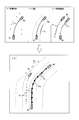
- FIG. 2 is a diagram for explaining a method of calculating the predicted course of the host vehicle.
- FIG. 3 is a diagram illustrating a preceding vehicle position and a movement locus in a preceding vehicle.
- FIG. 4 is a diagram for explaining the process for updating the preceding vehicle position.
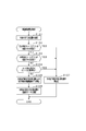
- FIG. 5 is a flowchart showing a processing procedure for calculating the movement trajectory of the preceding vehicle.
- the travel control device according to the present embodiment is mounted on a vehicle, and the host vehicle travels following the preceding vehicle traveling on the same lane as the host vehicle among the preceding vehicles traveling in front of the host vehicle.
- Follow-up control is performed.
- the follow-up control the inter-vehicle distance between the host vehicle and the preceding vehicle is controlled.
- a travel control device 10 is a computer having a CPU, ROM, RAM, I / O, and the like.
- the travel control apparatus 10 includes a course prediction unit 20, a follow-up vehicle setting unit 35, and a control target value calculation unit 36.
- the CPU executes each of these functions by executing a program installed in the ROM. Is realized.
- the vehicle (own vehicle) is equipped with object detection means for detecting an object existing around the vehicle.
- the travel control device 10 inputs object detection information from the object detection means, and executes tracking control for the preceding vehicle based on the input information.
- the own vehicle is provided with an imaging device 11 and a radar device 12 as object detection means.
- the imaging device 11 is an in-vehicle camera, and is composed of a CCD camera, a CMOS image sensor, a near infrared camera, and the like.
- the imaging device 11 captures the surrounding environment including the traveling road of the host vehicle, generates image data representing the captured image, and sequentially outputs the image data to the traveling control device 10.
- the imaging device 11 is installed, for example, in the vicinity of the upper end of the windshield of the host vehicle, and captures an area that extends in the range of the predetermined angle ⁇ 1 toward the front of the vehicle with the imaging axis as the center.
- the imaging device 11 may be a monocular camera or a stereo camera.
- the radar device 12 is a detection device that detects an object by transmitting an electromagnetic wave as a transmission wave (probing wave) and receiving the reflected wave, and is configured by a millimeter wave radar in this embodiment.
- the radar device 12 is attached to the front portion of the host vehicle, and scans an area that spreads over a range of a predetermined angle ⁇ 2 ( ⁇ 2 ⁇ 1) around the optical axis toward the front of the vehicle using a radar signal. Then, distance measurement data is created based on the time from transmission of electromagnetic waves toward the front of the vehicle until reception of the reflected wave, and the created distance measurement data is sequentially output to the travel control device 10.
- the distance measurement data includes information on the direction in which the object exists, the distance to the object, and the relative speed.
- the radar device 12 corresponds to a “vehicle distance sensor”.
- the imaging device 11 and the radar device 12 each have an imaging axis that is the reference axis of the imaging device 11 and an optical axis that is the reference axis of the radar device 12 parallel to the traveling road surface of the host vehicle. It is attached so as to be in the same direction as any other direction. At least a part of the detectable region of the imaging device 11 and the detectable region of the radar device 12 overlap each other.
- the traveling control device 10 inputs image data from the imaging device 11 and distance measurement data from the radar device 12, and also inputs detection signals from various sensors provided in the vehicle.
- a yaw rate sensor 13 for detecting an angular velocity (hereinafter referred to as “yaw rate”) in a turning direction of the vehicle a vehicle speed sensor 14 for detecting a vehicle speed, and the like are provided.
- a steering angle sensor 15 that detects the steering angle
- an ACC switch 16 that is operated when the driver selects the follow-up control mode, and the like are provided.
- the vehicle is also provided with a direction indicator 17 that is a device that displays the traveling direction of the vehicle outside the vehicle.
- the direction indicator 17 includes an operation lever that is operated by the driver to any one of the left instruction position, the neutral position, and the right instruction position, and inputs an operation signal corresponding to the position of the operation lever to the travel control device 10. .
- the course prediction unit 20 is a calculation unit that predicts a future travel course of the host vehicle, and includes a stationary object information acquisition unit 23, a white line information acquisition unit 24, another vehicle movement trajectory acquisition unit 25, a curve radius estimation unit 26, a predicted course. A calculation unit 21 and an invalidation determination unit 27 are provided.
- the course prediction unit 20 predicts the travel course of the host vehicle based on the movement trajectory of the preceding vehicle that travels in front of the host vehicle.
- the stationary object information acquisition unit 23 calculates position information regarding a roadside stationary object (for example, a guardrail or a wall) existing along the road on the traveling road of the host vehicle based on the distance measurement data from the radar device 12.
- the position information is output to the predicted course calculation unit 21 as stationary object information.
- the white line information acquisition unit 24 calculates information on road lane markings (white lines) included in the image captured by the imaging device 11 based on the image data from the imaging device 11, and uses the calculated information as white line information.
- the white line information calculation method extracts edge points as white line candidates from the image data based on, for example, the luminance change rate in the horizontal direction of the image. Then, the extracted edge points are sequentially stored for each frame, and white line information is calculated based on the stored history of white line edge points.
- the other vehicle movement trajectory acquisition unit 25 determines the position of the preceding vehicle (coordinates representing the passing point of the preceding vehicle) based on the distance measurement data from the radar device 12 (distance information and lateral position information between the host vehicle and the preceding vehicle).
- the preceding vehicle position is calculated at a predetermined cycle, and the calculated preceding vehicle position is stored in time series.
- the movement trajectory of the preceding vehicle is calculated based on the stored time-series data of the preceding vehicle position, and the calculated movement trajectory is output to the predicted course calculation unit 21 as other vehicle movement trajectory information.
- the other-vehicle movement trajectory acquisition unit 25 calculates the movement trajectory information of not only a vehicle traveling on the same lane as the host vehicle but also a vehicle traveling on a lane adjacent to the host vehicle among preceding vehicles. This may be used for the course prediction of the host vehicle.
- the curve radius estimation unit 26 calculates a curve radius (hereinafter referred to as “estimated R”) of the traveling road of the host vehicle from the yaw angle detected by the yaw rate sensor 13 and the vehicle speed detected by the vehicle speed sensor 14. Note that the calculation method of the estimated R is not limited to this, and may be calculated using, for example, image data, or may be calculated from the steering angle detected by the steering angle sensor 15 and the vehicle speed detected by the vehicle speed sensor 14. May be.
- the predicted course calculation unit 21 receives the stationary object information from the stationary object information acquisition unit 23, the white line information from the white line information acquisition unit 24, and the other vehicle movement locus information from the other vehicle movement locus acquisition unit 25. Thereby, the predicted course RA which is a predicted value of the future traveling course of the own vehicle is calculated by combining the input information. Note that the predicted course calculation unit 21 can predict the course of the host vehicle independent of the yaw rate of the host vehicle.
- FIG. 2 shows an outline of a procedure for calculating the predicted route RA in the predicted route calculation unit 21.
- 2A shows a plurality of stationary object detection points Pa as a result of recognizing a three-dimensional obstacle (for example, a guard rail) as a roadside stationary object by the radar device 12.
- (b) shows white line information Pb which is a result of recognizing the white line by the imaging apparatus 11.
- (C) shows the history of a plurality of vehicle detection points Pc, which is the result of recognizing the preceding vehicle M2 by the radar device 12.
- FIG. 2 (c) shows, as the preceding vehicle M2, a vehicle traveling on the same lane as the own vehicle M1 and a vehicle traveling on a lane adjacent to the own vehicle M1.
- (d) shows the predicted course RA calculated using the stationary object detection point Pa, the white line information Pb, and the vehicle detection point Pc.
- the predicted course calculation unit 21 first, the movement trajectory of the preceding vehicle M2 calculated from the vehicle detection point Pc is compared with the white line and the three-dimensional obstacle, respectively, and the preceding vehicle M2 that does not match the shape of the white line and the three-dimensional obstacle is detected. Exclude (disable) the movement trajectory. Subsequently, when there is only one moving locus of the preceding vehicle M2 that is not excluded, the predicted route RA is calculated by weighted averaging the moving locus of the preceding vehicle M2 and the white line information Pb using the movement locus. To do.
- the predicted trajectory RA is obtained by weighted averaging the movement trajectory of the preceding vehicle M2 and the white line information Pb using the movement trajectory obtained by averaging them. Is calculated.
- the predicted course calculation unit 21 corresponds to a “course calculation unit”.
- the following vehicle setting unit 35 uses the predicted route RA of the host vehicle M1 input from the route prediction unit 20, and follows the preceding vehicle M2 existing on the predicted track among the preceding vehicles M2 traveling in front of the host vehicle M1.
- the control target value calculation unit 36 controls the traveling speed of the host vehicle M1, thereby obtaining a control target value for maintaining the inter-vehicle distance between the tracking vehicle set by the tracking vehicle setting unit 35 and the host vehicle M1. calculate.
- the control target value calculation unit 36 calculates a control target value for maintaining the inter-vehicle distance at a preset target interval. Specifically, the target output of the vehicle-mounted engine, the required brake force, and the like are calculated and output to the engine electronic control unit (engine ECU 41).
- the travel control device 10 is configured to output a control signal to the engine ECU 41 and to output a control signal from the engine ECU 41 to the brake electronic control unit (brake ECU 42).
- brake ECU 42 the brake electronic control unit
- the other vehicle movement locus acquisition unit 25 includes a preceding vehicle position storage unit 25a, a movement locus calculation unit 25b, and a preceding vehicle position update unit 25c.
- the preceding vehicle position storage unit 25a calculates the preceding vehicle position in a predetermined cycle based on the distance measurement data from the radar device 12, and stores the calculated preceding vehicle position in a predetermined storage area (storage device) in time series. .
- a value obtained by averaging the vehicle detection points Pc for each predetermined section is set as the value of the preceding vehicle position Pd.
- FIG. 3 shows the preceding vehicle position Pd and the movement locus RT of the preceding vehicle M2 traveling ahead of the host vehicle M1.
- a plurality of sections are set, for example, at an interval of 10 m in front of the host vehicle M1, and the preceding vehicle position Pd is calculated for each section.
- the preceding vehicle position storage unit 25a calculates the preceding vehicle position Pd by averaging the vehicle detection points Pc in each unit section with each of the sections K1 to K5 as one unit section.
- the calculated preceding vehicle position Pd for each unit section is stored in time series in association with the section.
- the preceding vehicle position storage unit 25a corresponds to “position storage means”.
- the movement locus calculation unit 25b reads time-series data of the preceding vehicle position Pd from the preceding vehicle position storage unit 25a. Further, the axis of the trajectory that each vehicle has moved is extracted from the read preceding vehicle position Pd, and this is taken as the moving trajectory RT of the preceding vehicle M2.
- the preceding vehicle position Pd of the adjacent unit sections is connected by, for example, a straight line, and a locus generated by connecting the straight lines is defined as a movement locus RT of the preceding vehicle M2.
- the preceding vehicle position update unit 25c calculates the movement trajectory RT of the preceding vehicle M2, the value of the preceding vehicle position Pd stored in time series in the preceding vehicle position storage unit 25a is set as the previous value.
- Update Specifically, the vehicle speed of the host vehicle M1 detected by the vehicle speed sensor 14 and the yaw rate of the host vehicle M1 detected by the yaw rate sensor 13 are input to the preceding vehicle position update unit 25c.
- the preceding vehicle position update unit 25c performs coordinate conversion of the preceding vehicle position Pd stored in time series in the preceding vehicle position storage unit 25a based on the input vehicle speed and yaw rate. Then, the value of the preceding vehicle position after coordinate conversion is updated as the previous value.
- the updated value is stored in time series as the previous value in the preceding vehicle position storage unit 25a.
- the procedure for updating the preceding vehicle position Pd by coordinate conversion will be described with reference to FIG.
- two points of the position Q (i) and the position R (i) are shown as the preceding vehicle position Pd before the update.
- the preceding vehicle position update unit 25c uses the estimated R calculated based on the vehicle speed and yaw rate of the host vehicle M1, and each of the position Q (i) and the position R (i) by a rotation matrix having the virtual center O as the origin. Is transformed. Further, the respective values of the position Q (i ⁇ 1) and the position R (i ⁇ 1) after the coordinate conversion are updated as the values one time before the preceding vehicle position Pd.
- the position Q (i) approaches the host vehicle M1 by x1 in the X axis direction along with the coordinate conversion.
- the vehicle approaches the vehicle M1 by y1 in the Y-axis direction.
- the position R (i) approaches the host vehicle M1 by x2 in the X-axis direction and approaches the host vehicle M1 by y2 in the Y-axis direction along with the coordinate conversion.
- the preceding vehicle position update unit 25c corresponds to “position update means”.
- the course is arbitrarily changed according to the intention of the driver of each vehicle, and a situation inappropriate for the calculation of the movement trajectory RT of the preceding vehicle M2 may occur.
- the movement trajectory RT of the preceding vehicle M2 is calculated using the preceding vehicle position Pd acquired under such an inappropriate situation and the course prediction of the host vehicle M1 is performed, a highly accurate prediction result cannot be obtained. There is a concern that the controllability of the driving support is lowered.
- the preceding vehicle position Pd stored in the preceding vehicle position storage unit 25a Is going to be disabled.
- the travel control apparatus 10 uses an invalidation determination unit 27 as a means for invalidating the preceding vehicle position Pd stored in the preceding vehicle position storage unit 25a.
- the invalidation determination unit 27 includes a course out determination unit 27a and a sensor accuracy determination unit 27b.
- the course-out determination unit 27a determines whether one of the host vehicle M1 and the preceding vehicle M2 is estimated to turn right or left based on the vehicle speeds of the host vehicle M1 and the preceding vehicle M2. Specifically, the preceding vehicle M2 is traveling at a low speed (hereinafter referred to as “first estimation condition”), and the host vehicle M1 is traveling at a low speed (hereinafter referred to as “second estimation condition”). It is determined whether at least one of the above holds.
- the reason why the above estimation condition is adopted as the determination method is that there is a possibility that the vehicle M1 and the preceding vehicle M2 that are following the vehicle are in a state of preparing to turn right or left when the vehicle M1 enters low speed. Because there is.
- the first estimation condition is determined based on distance measurement data from the radar device 12, and the second estimation condition is determined based on the detection value of the vehicle speed sensor 14.
- the course-out determination unit 27a outputs an invalidation signal to the other vehicle movement locus acquisition unit 25 when it is determined that at least one of the first estimation condition and the second estimation condition is satisfied.
- the sensor accuracy determination unit 27b determines whether or not the positional relationship between the host vehicle M1 and the preceding vehicle M2 is a positional relationship in which the detection accuracy of the radar device 12 decreases, based on distance measurement data from the radar device 12. To do. Specifically, it is determined whether at least one of the following estimation conditions is satisfied.
- the estimation condition is that the inter-vehicle distance between the host vehicle M1 and the preceding vehicle M2 is extremely long (greater than a predetermined distance) (hereinafter referred to as “third estimation condition”). Further, the preceding vehicle M2 deviates from the front position of the host vehicle M1 and exists in the wide-angle region of the sensor (hereinafter referred to as “fourth estimation condition”).
- the sensor accuracy determination unit 27b outputs an invalidation signal to the other vehicle movement locus acquisition unit 25 when at least one of these estimation conditions is satisfied.
- the invalidation determination unit 27 corresponds to “invalidation means”.
- the other vehicle movement locus acquisition unit 25 is stored in the preceding vehicle position storage unit 25a.
- the preceding vehicle position Pd is invalidated.
- all of the preceding vehicle positions Pd stored in time series in the preceding vehicle position storage unit 25a may be invalidated, but deviate from the current running path. Only the preceding vehicle position Pd related to the preceding vehicle M2 that is estimated to be invalid may be invalidated.
- the process which erases the information, the process which prohibits use of information, etc. are mentioned.
- This process is a process performed by the other vehicle movement locus acquisition unit 25 and the invalidation determination unit 27. Further, when the vehicle is traveling and the ACC switch 16 is in the ON state, the ECU is executed at predetermined intervals by the ECU of the traveling control device 10.
- FIG. 5 is a flowchart showing a processing procedure for calculating the movement trajectory of the preceding vehicle M2.
- the travel control device 10 acquires the preceding vehicle position Pd calculated in the current calculation cycle in step S101.
- step S102 it is determined whether or not the preceding vehicle M2 is in a situation where it is estimated that the preceding vehicle M2 deviates from the current running path (the preceding vehicle M2 goes out of the course).
- the determination condition here is determined by whether or not the preceding vehicle M2 is traveling at a low speed (whether or not the first estimation condition is satisfied).
- step S102 when it is determined that the course out of the preceding vehicle M2 is estimated (when affirmative determination is made in step S102), the process proceeds to step S107 and is stored in the preceding vehicle position storage unit 25a in time series.
- the previous and previous preceding vehicle positions Pd are invalidated.
- the preceding vehicle M2 is in a decelerating state or traveling at a low vehicle speed (for example, several km / h to several tens of km / h) continues for a predetermined time (for example, several seconds), It is determined that the preceding vehicle M2 is traveling at a low speed, and it is determined that the course out of the preceding vehicle M2 is estimated.
- step S102 when it is determined that the course of the preceding vehicle M2 is not estimated to be in a situation (when a negative determination is made in step S102), the process proceeds to step S103, and the host vehicle M1 deviates from the current travel path ( It is determined whether or not it is estimated that the vehicle M1 is going out of the course.
- the determination condition here is determined by whether or not the host vehicle M1 is traveling at a low speed (whether or not the second estimation condition is satisfied).
- step S107 when it is determined that the course out of the host vehicle M1 is estimated (when affirmative determination is made in step S103), the process proceeds to step S107, and is stored in time series in the preceding vehicle position storage unit 25a.
- the previous and previous preceding vehicle positions Pd are invalidated. If the host vehicle M1 is in a decelerating state or if traveling at a low speed continues for a predetermined time, it is determined that the host vehicle M1 is traveling at a low speed, and the vehicle M1 is out of course. Is determined to be the estimated situation.
- step S104 the process proceeds to step S104, and the positions of the host vehicle M1 and the preceding vehicle M2 are determined. It is determined whether or not the relationship is a positional relationship at which the detection accuracy of the radar device 12 decreases.
- the determination condition here is one of the following. First, it is determined whether or not the distance between the host vehicle M1 and the preceding vehicle M2 is extremely long (whether or not the third estimation condition is satisfied). Second, it is determined whether or not the preceding vehicle M2 deviates from the front position of the host vehicle M1 and exists in the wide-angle region of the sensor (whether or not the fourth estimation condition is satisfied).
- the third is determined by whether or not the relative speed between the preceding vehicle M2 and the host vehicle M1 is high (whether or not the fifth estimation condition is satisfied).
- the process proceeds to step S107 and is stored in time series in the preceding vehicle position storage unit 25a.
- the previous and previous preceding vehicle positions Pd are invalidated.
- step S104 the traveling control device 10 validates the current and past preceding vehicle positions Pd stored in the preceding vehicle position storage unit 25a in time series, and based on the time series data of the preceding vehicle position Pd.
- the movement trajectory RT of the preceding vehicle M2 is calculated.
- step S106 the current and past preceding vehicle positions Pd are coordinate-converted using a rotation matrix, and the value of the preceding vehicle position Pd after the coordinate conversion is updated as the previous value.
- the traveling control device 10 when it is determined that one of the host vehicle M1 and the preceding vehicle M2 is estimated to be out of the current traveling path, the travel locus RT of the preceding vehicle M2.
- the preceding vehicle position Pd which is information indicating that is invalidated.
- the prediction accuracy may be reduced if the route of the host vehicle M1 is predicted using the data. Conceivable.
- the traveling control apparatus 10 which concerns on this embodiment can suppress beforehand that the prediction precision of the course of the own vehicle M1 falls by setting it as the said structure.
- the travel control apparatus 10 determines that either the host vehicle M1 or the preceding vehicle M2 is in a situation where it is estimated that the vehicle will make a right turn or a left turn. As a result, when it is determined that a right turn or left turn is estimated, the preceding vehicle position Pd stored in time series in the preceding vehicle position storage unit 25a is invalidated. When the course prediction of the host vehicle M1 is performed using the preceding vehicle position Pd after the right turn or the left turn is started, the prediction accuracy of the course prediction of the host vehicle M1 is likely to be reduced.
- the travel control apparatus 10 has the above-described configuration to suppress a decrease in the accuracy of the course prediction of the host vehicle M1 due to the right turn or the left turn of the preceding vehicle M2 or the host vehicle M1. it can.
- the traveling control apparatus 10 determines that either the host vehicle M1 or the preceding vehicle M2 is traveling at a low speed, and the current and past preceding vehicles. The position Pd is invalidated. In this configuration, it is preferable to avoid performing the course prediction of the host vehicle M1 using data that may cause a decrease in prediction accuracy.
- the traveling control device 10 is configured to invalidate the preceding vehicle position Pd stored in the preceding vehicle position storage unit 25a in such a situation. Thereby, it can suppress that the prediction precision of the movement track
- the travel control apparatus 10 performs coordinate conversion of the preceding vehicle position Pd for each time series based on the estimated R calculated from the vehicle speed and yaw rate of the host vehicle M1.
- the value of the preceding vehicle position after the coordinate conversion is updated as the previous value.
- the predicted route calculation unit 21 is configured to input stationary object information, white line information, and other vehicle movement trajectory information, and calculate the predicted route RA using these input information.
- the method of calculating the predicted course RA is not limited to this, and for example, the predicted course RA may be calculated using only other vehicle movement trajectory information. Further, the predicted course RA may be calculated from the other vehicle movement locus information and the stationary object information, or the predicted course RA may be calculated from the other vehicle movement locus information and the white line information.
- the host vehicle M1 and the preceding vehicle M2 travels at a low speed.
- the configuration is made by determining whether or not the situation is in progress.
- the method for determining whether one of the host vehicle M1 and the preceding vehicle M2 is in a situation where it is estimated that the vehicle turns right or left is not limited to the method based on the vehicle speed.
- the determination method sets determination conditions such as recognition of lighting of the brake lamp of the preceding vehicle M2 and recognition of lighting of the direction indicator of the preceding vehicle M2, and makes a determination based on whether or not the condition is met. May be.
- the brake operation for deceleration is performed in the own vehicle M1 and the direction indicator 17 is operated in the own vehicle M1 based on the success or failure of the condition. May be. Further, by combining these determination conditions and the determination condition that the vehicle is traveling at a low speed, it is determined that either the host vehicle M1 or the preceding vehicle M2 is in a situation where it is estimated that the vehicle will turn right or left. It is good. Note that when the determination condition is that the brake lamp of the preceding vehicle M2 is lit and the direction indicator of the preceding vehicle M2 is lit, image data captured by the imaging device 11 may be used.
- the current and past preceding vehicle positions Pd are invalidated. Also good. This is because if the lane change is performed, the preceding vehicle M2 deviates from the front position of the host vehicle M1 (enters the wide-angle region of the sensor), and the detection accuracy may be reduced. Note that whether one of the host vehicle M1 and the preceding vehicle M2 is in a situation where it is estimated that the lane is changed is, for example, the fact that the turn indicator of the preceding vehicle M2 has been recognized, or the host vehicle M1. In this case, the determination may be made based on the operation of the direction indicator 17 or the like.
- the configuration for invalidating the acquired preceding vehicle position Pd is not limited to the configuration for deleting the preceding vehicle position Pd stored in the preceding vehicle position storage unit 25a or prohibiting its use.
- a configuration for deleting the movement locus RT calculated using the preceding vehicle position Pd stored in the preceding vehicle position storage unit 25a or a configuration for prohibiting the use of the movement locus RT calculated using the preceding vehicle position Pd.
- a value obtained by averaging the vehicle detection points Pc for each predetermined section is set as the preceding vehicle position Pd, and a track connecting the preceding vehicle positions Pd of adjacent unit sections with a straight line is defined as the moving track RT of the preceding vehicle M2. It was set as the structure to do.
- the preceding vehicle position Pd is not limited to an averaged value for each predetermined section of the vehicle detection point Pc.
- the preceding vehicle position Pd may be the vehicle detection point Pc itself.
- the movement trajectory RT of the preceding vehicle M2 is not limited to a trajectory that connects the preceding vehicle positions Pd of adjacent unit sections with a straight line.
- the moving locus RT may be calculated by averaging the vehicle detection points Pc.
- the imaging device 11 and the radar device 12 are provided as the object detection means.
- the present invention is not limited thereto.
- the invention is applied to a configuration including a sonar that detects an object using an ultrasonic wave as a transmission wave. Also good.
- the technology of the present disclosure may be applied to a vehicle that does not include the imaging device 11.
- the present invention is applied to follow-up control that travels following the preceding vehicle M2 that travels on the same lane as the host vehicle M1.
- the technology of the present disclosure may be applied to the course prediction of the host vehicle M1 for avoiding a collision between the host vehicle M1 and another vehicle.
- the present disclosure includes various programs such as a program for causing a computer to execute each functional unit (each unit) constituting the travel control device 10, a medium on which the program is recorded, and a vehicle travel control method. It can also be realized in the form.
Landscapes
- Engineering & Computer Science (AREA)
- Remote Sensing (AREA)
- Radar, Positioning & Navigation (AREA)
- Physics & Mathematics (AREA)
- General Physics & Mathematics (AREA)
- Computer Networks & Wireless Communication (AREA)
- Electromagnetism (AREA)
- Theoretical Computer Science (AREA)
- Multimedia (AREA)
- Mechanical Engineering (AREA)
- Transportation (AREA)
- Combustion & Propulsion (AREA)
- Chemical & Material Sciences (AREA)
- Traffic Control Systems (AREA)
- Control Of Driving Devices And Active Controlling Of Vehicle (AREA)
- Controls For Constant Speed Travelling (AREA)
Abstract
Description
本開示は上記実施形態に限定されず、例えば次のように実施してもよい。
Claims (11)
- 自車両(M1)の将来の走行進路である予測進路に基づいて車両の走行を制御する車両の走行制御装置(10)であって、
前記自車両の前方を走行する先行車両(M2)の位置である先行車位置を時系列で記憶する位置記憶手段(25a)と、
前記位置記憶手段に記憶されている前記先行車位置の軌跡に基づいて前記予測進路を算出する進路算出手段(21)と、
前記自車両及び前記先行車両のいずれかが走路から外れることが推定される状況であるか否かを判定し、前記自車両及び前記先行車両のいずれかが走路から外れることが推定される状況であると判定された場合に、前記位置記憶手段に記憶されている前記先行車位置を無効にする無効化手段(27)と、
を備える車両の走行制御装置。 - 前記無効化手段は、前記自車両及び前記先行車両のいずれかが、右折、左折、又は車線変更することが推定される状況である場合に、前記自車両及び前記先行車両のいずれかが走路から外れることが推定される状況であるものと判定する請求項1に記載の車両の走行制御装置。
- 前記無効化手段は、前記自車両及び前記先行車両のいずれかが低速走行している状況である場合に、前記自車両及び前記先行車両のいずれかが走路から外れることが推定される状況であるものと判定する請求項1又は2に記載の車両の走行制御装置。
- 前記自車両には、探査波の送信及び受信により前記自車両と前記先行車両との車間距離を検出する車間距離センサ(12)が備えられており、
前記位置記憶手段は、前記車間距離センサの検出値に基づき算出した前記先行車位置を記憶し、
前記無効化手段は、前記自車両と前記先行車両との位置関係が、前記車間距離センサの検出精度が低下する位置関係にあるか否かを判定し、前記位置関係にあると判定された場合に、前記位置記憶手段に記憶されている前記先行車位置を無効にする請求項1乃至3のいずれか一項に記載の車両の走行制御装置。 - 前記無効化手段は、前記自車両と前記先行車両との車間距離が所定距離より長い場合に、前記自車両と前記先行車両との位置関係が、前記車間距離センサの検出精度が低下する位置関係にあると判定する請求項4に記載の車両の走行制御装置。
- 前記無効化手段は、前記先行車両が前記自車両の正面位置から外れ、前記車間距離センサの広角領域に存在している場合に、前記自車両と前記先行車両との位置関係が、前記車間距離センサの検出精度が低下する位置関係にあると判定する請求項4又は5に記載の車両の走行制御装置。
- 前記無効化手段は、前記先行車両と前記自車両との相対速度が大きい場合に、前記自車両と前記先行車両との位置関係が、前記車間距離センサの検出精度が低下する位置関係にあると判定する請求項4乃至6のいずれか一項に記載の車両の走行制御装置。
- 前記無効化手段により前記自車両及び前記先行車両のいずれも走路から外れることが推定される状況でないと判定され、前記位置記憶手段に記憶されている前記先行車位置を有効にする場合に、前記先行車両の移動軌跡を算出するたびに、前記位置記憶手段に記憶されている先行車位置をそれぞれ1回前の値として更新する位置更新手段(25c)を備え、
前記位置更新手段は、前記自車両の車速とヨーレートとに基づいて前記位置記憶手段に記憶されている先行車位置の座標変換を実施し、該座標変換後の先行車位置の値を1回前の値として更新する請求項1乃至7のいずれか一項に記載の車両の走行制御装置。 - 自車両(M1)の将来の走行進路である予測進路に基づいて自車両の走行を制御する車両の走行制御装置(10)であって、
前記自車両の前方を走行する先行車両(M2)の位置である先行車位置を時系列で記憶する位置記憶手段(25a)と、
前記位置記憶手段に記憶されている前記先行車位置の軌跡に基づいて前記予測進路を算出する進路算出手段(21)と、
前記先行車両の移動軌跡を算出するたびに、前記位置記憶手段に記憶されている先行車位置の値をそれぞれ1回前の値として更新する位置更新手段(25c)と、を備え、
前記位置更新手段は、前記自車両の車速とヨーレートとに基づいて、前記位置記憶手段に記憶されている先行車位置の座標変換を実施し、該座標変換後の先行車位置の値を1回前の値として更新する車両の走行制御装置。 - 自車両(M1)の将来の走行進路である予測進路に基づいて車両の走行を制御する車両の走行制御方法であって、
前記自車両の前方を走行する先行車両(M2)の位置である先行車位置を所定の記憶装置に時系列で記憶する工程(25a)と、
前記記憶装置に記憶されている前記先行車位置の軌跡に基づいて前記予測進路を算出する工程(21)と、
前記自車両及び前記先行車両のいずれかが走路から外れることが推定される状況であるか否かを判定し、前記自車両及び前記先行車両のいずれかが走路から外れることが推定される状況であると判定された場合に、前記記憶装置に記憶されている前記先行車位置を無効にする工程(27)と、
を含む車両の走行制御方法。 - 自車両(M1)の将来の走行進路である予測進路に基づいて車両の走行を制御する車両の走行制御プログラムであって、
前記自車両の前方を走行する先行車両(M2)の位置である先行車位置を所定の記憶装置に時系列で記憶する位置記憶ステップ(25a)と、
前記記憶装置に記憶されている前記先行車位置の軌跡に基づいて前記予測進路を算出する進路算出ステップ(21)と、
前記自車両及び前記先行車両のいずれかが走路から外れることが推定される状況であるか否かを判定し、前記自車両及び前記先行車両のいずれかが走路から外れることが推定される状況であると判定された場合に、前記記憶装置に記憶されている前記先行車位置を無効にする無効化ステップ(27)と、
をコンピュータに実行させる車両の走行制御プログラム。
Priority Applications (3)
| Application Number | Priority Date | Filing Date | Title |
|---|---|---|---|
| CN201580064901.XA CN107004368B (zh) | 2014-11-28 | 2015-10-05 | 车辆的行驶控制装置以及行驶控制方法 |
| US15/529,915 US10350999B2 (en) | 2014-11-28 | 2015-10-05 | Vehicle cruise control apparatus and vehicle cruise control method |
| DE112015005329.8T DE112015005329B4 (de) | 2014-11-28 | 2015-10-05 | Fahrzeuggeschwindigkeitsregelungsvorrichtung, fahrzeuggeschwindigkeitsregelungsverfahren und fahrzeuggeschwindigkeitsregelungsprogramm |
Applications Claiming Priority (2)
| Application Number | Priority Date | Filing Date | Title |
|---|---|---|---|
| JP2014-242235 | 2014-11-28 | ||
| JP2014242235A JP6356585B2 (ja) | 2014-11-28 | 2014-11-28 | 車両の走行制御装置 |
Publications (1)
| Publication Number | Publication Date |
|---|---|
| WO2016084479A1 true WO2016084479A1 (ja) | 2016-06-02 |
Family
ID=56074057
Family Applications (1)
| Application Number | Title | Priority Date | Filing Date |
|---|---|---|---|
| PCT/JP2015/078154 Ceased WO2016084479A1 (ja) | 2014-11-28 | 2015-10-05 | 車両の走行制御装置、走行制御方法、及び走行制御プログラム |
Country Status (5)
| Country | Link |
|---|---|
| US (1) | US10350999B2 (ja) |
| JP (1) | JP6356585B2 (ja) |
| CN (1) | CN107004368B (ja) |
| DE (1) | DE112015005329B4 (ja) |
| WO (1) | WO2016084479A1 (ja) |
Cited By (2)
| Publication number | Priority date | Publication date | Assignee | Title |
|---|---|---|---|---|
| JP2018083587A (ja) * | 2016-11-25 | 2018-05-31 | 株式会社デンソー | 車両制御装置 |
| WO2020059068A1 (ja) * | 2018-09-20 | 2020-03-26 | 三菱電機株式会社 | 車両位置処理装置、車両制御装置、車両位置処理方法、及び車両制御方法 |
Families Citing this family (21)
| Publication number | Priority date | Publication date | Assignee | Title |
|---|---|---|---|---|
| JP6327719B2 (ja) * | 2016-02-04 | 2018-05-23 | 株式会社Subaru | 車両の走行制御装置 |
| DE102016202951A1 (de) * | 2016-02-25 | 2017-08-31 | Continental Teves Ag & Co. Ohg | Verfahren für einen Geschwindigkeitsregler |
| JP6747405B2 (ja) * | 2017-08-25 | 2020-08-26 | トヨタ自動車株式会社 | 自車位置自信度演算装置 |
| TWI665114B (zh) * | 2017-08-25 | 2019-07-11 | Institute For Information Industry | 車輛行駛偵測方法及車輛行駛偵測系統 |
| JP7116355B2 (ja) | 2017-09-28 | 2022-08-10 | トヨタ自動車株式会社 | 運転支援装置 |
| JP6946972B2 (ja) * | 2017-11-24 | 2021-10-13 | トヨタ自動車株式会社 | 車両制御装置 |
| US11068735B2 (en) | 2017-12-05 | 2021-07-20 | Denso Corporation | Reliability calculation apparatus |
| KR102464607B1 (ko) * | 2017-12-27 | 2022-11-08 | 현대자동차주식회사 | 차량 및 그 제어 방법 |
| JP6602418B1 (ja) * | 2018-05-09 | 2019-11-06 | 三菱電機株式会社 | 車両動き予測装置及び車両動き予測方法 |
| JP7132057B2 (ja) * | 2018-09-27 | 2022-09-06 | 株式会社Subaru | 車両用通信装置、並びにこれを用いる車両制御システムおよび交通システム |
| DE102018008624A1 (de) * | 2018-10-31 | 2020-04-30 | Trw Automotive Gmbh | Steuerungssystem und Steuerungsverfahren zum samplingbasierten Planen möglicher Trajektorien für Kraftfahrzeuge |
| CN109782754B (zh) * | 2018-12-25 | 2022-05-06 | 东软睿驰汽车技术(沈阳)有限公司 | 一种车辆控制方法及装置 |
| US12304487B2 (en) * | 2019-03-21 | 2025-05-20 | The Regents Of The University Of Michigan | Safe autonomous overtaking with intention estimation |
| KR102673140B1 (ko) * | 2019-11-29 | 2024-06-10 | 현대모비스 주식회사 | 주변 차량을 활용한 곡률 정보 보정 시스템 및 방법 |
| US20230031419A1 (en) * | 2020-01-27 | 2023-02-02 | Mitsubishi Electric Corporation | Preceding vehicle determination system and preceding vehicle determination method |
| JP2023012067A (ja) * | 2021-07-13 | 2023-01-25 | パナソニックIpマネジメント株式会社 | 測定装置、測定方法、および測定プログラム |
| US12125222B1 (en) | 2023-03-31 | 2024-10-22 | Geotab Inc. | Systems for determining and reporting vehicle following distance |
| US12586230B2 (en) | 2023-03-31 | 2026-03-24 | Geotab Inc. | Systems and methods for training a model for determining vehicle following distance |
| US11989949B1 (en) | 2023-03-31 | 2024-05-21 | Geotab Inc. | Systems for detecting vehicle following distance |
| US12456305B2 (en) | 2023-03-31 | 2025-10-28 | Geotab Inc. | Systems and methods for identifying tailgating |
| US12423864B2 (en) | 2023-03-31 | 2025-09-23 | Geotab Inc. | Systems for detecting vehicle following distance |
Citations (4)
| Publication number | Priority date | Publication date | Assignee | Title |
|---|---|---|---|---|
| JP2002099904A (ja) * | 2000-07-18 | 2002-04-05 | Honda Motor Co Ltd | 車両用走行区分線検出装置 |
| JP2002211270A (ja) * | 2000-11-16 | 2002-07-31 | Honda Motor Co Ltd | オートクルーズ装置 |
| JP2004078333A (ja) * | 2002-08-12 | 2004-03-11 | Nissan Motor Co Ltd | 走行経路生成装置 |
| JP2008276689A (ja) * | 2007-05-07 | 2008-11-13 | Mitsubishi Electric Corp | 車両用障害物認識装置 |
Family Cites Families (11)
| Publication number | Priority date | Publication date | Assignee | Title |
|---|---|---|---|---|
| US6768944B2 (en) * | 2002-04-09 | 2004-07-27 | Intelligent Technologies International, Inc. | Method and system for controlling a vehicle |
| DE19855400A1 (de) | 1998-12-01 | 2000-06-15 | Bosch Gmbh Robert | Verfahren und Vorrichtung zur Bestimmung eines zukünftigen Kursbereichs eines Fahrzeugs |
| US6871145B2 (en) * | 2002-11-26 | 2005-03-22 | General Motors Corporation | Method and system for vehicle impact assessment using driver braking estimation |
| JP4453468B2 (ja) * | 2004-07-16 | 2010-04-21 | 日産自動車株式会社 | 先行車追従走行制御装置 |
| JP4720355B2 (ja) * | 2005-08-11 | 2011-07-13 | トヨタ自動車株式会社 | 車両制御装置 |
| EP2068120B1 (en) * | 2007-12-04 | 2010-08-11 | Research In Motion Limited | Mobile tracking |
| DE102010023196A1 (de) | 2010-06-09 | 2011-12-15 | Gm Global Technology Operations Llc (N.D.Ges.D. Staates Delaware) | Verfahren und Vorrichtung zur Vordermannerkennung |
| JP5672822B2 (ja) * | 2010-07-29 | 2015-02-18 | トヨタ自動車株式会社 | 車両制御システム |
| JP5829585B2 (ja) * | 2012-08-07 | 2015-12-09 | 株式会社デンソー | 制御システム及び車両操舵制御システム |
| CN103640622B (zh) * | 2013-11-13 | 2016-01-20 | 南京航空航天大学 | 一种基于驾驶员模型的汽车方向智能控制方法及控制系统 |
| CN103646298B (zh) * | 2013-12-13 | 2018-01-02 | 中国科学院深圳先进技术研究院 | 一种自动驾驶方法及系统 |
-
2014
- 2014-11-28 JP JP2014242235A patent/JP6356585B2/ja active Active
-
2015
- 2015-10-05 DE DE112015005329.8T patent/DE112015005329B4/de active Active
- 2015-10-05 US US15/529,915 patent/US10350999B2/en active Active
- 2015-10-05 CN CN201580064901.XA patent/CN107004368B/zh active Active
- 2015-10-05 WO PCT/JP2015/078154 patent/WO2016084479A1/ja not_active Ceased
Patent Citations (4)
| Publication number | Priority date | Publication date | Assignee | Title |
|---|---|---|---|---|
| JP2002099904A (ja) * | 2000-07-18 | 2002-04-05 | Honda Motor Co Ltd | 車両用走行区分線検出装置 |
| JP2002211270A (ja) * | 2000-11-16 | 2002-07-31 | Honda Motor Co Ltd | オートクルーズ装置 |
| JP2004078333A (ja) * | 2002-08-12 | 2004-03-11 | Nissan Motor Co Ltd | 走行経路生成装置 |
| JP2008276689A (ja) * | 2007-05-07 | 2008-11-13 | Mitsubishi Electric Corp | 車両用障害物認識装置 |
Cited By (8)
| Publication number | Priority date | Publication date | Assignee | Title |
|---|---|---|---|---|
| JP2018083587A (ja) * | 2016-11-25 | 2018-05-31 | 株式会社デンソー | 車両制御装置 |
| WO2018097026A1 (ja) * | 2016-11-25 | 2018-05-31 | 株式会社デンソー | 車両制御装置 |
| CN109982909A (zh) * | 2016-11-25 | 2019-07-05 | 株式会社电装 | 车辆控制装置 |
| CN109982909B (zh) * | 2016-11-25 | 2022-05-10 | 株式会社电装 | 车辆控制装置 |
| US11373533B2 (en) | 2016-11-25 | 2022-06-28 | Denso Corporation | Vehicle control apparatus |
| WO2020059068A1 (ja) * | 2018-09-20 | 2020-03-26 | 三菱電機株式会社 | 車両位置処理装置、車両制御装置、車両位置処理方法、及び車両制御方法 |
| JPWO2020059068A1 (ja) * | 2018-09-20 | 2021-02-15 | 三菱電機株式会社 | 車両位置処理装置、車両制御装置、車両位置処理方法、及び車両制御方法 |
| US11970207B2 (en) | 2018-09-20 | 2024-04-30 | Mitsubishi Electric Corporation | Vehicle control apparatus and vehicle control method |
Also Published As
| Publication number | Publication date |
|---|---|
| US20170326981A1 (en) | 2017-11-16 |
| DE112015005329B4 (de) | 2025-12-04 |
| CN107004368A (zh) | 2017-08-01 |
| CN107004368B (zh) | 2020-10-02 |
| DE112015005329T5 (de) | 2017-08-31 |
| JP2016103224A (ja) | 2016-06-02 |
| US10350999B2 (en) | 2019-07-16 |
| DE112015005329T8 (de) | 2017-09-21 |
| JP6356585B2 (ja) | 2018-07-11 |
Similar Documents
| Publication | Publication Date | Title |
|---|---|---|
| JP6356585B2 (ja) | 車両の走行制御装置 | |
| JP6321532B2 (ja) | 車両の走行制御装置 | |
| JP6356586B2 (ja) | 車両の走行制御装置 | |
| CN107004367B (zh) | 车辆的行驶控制装置以及行驶控制方法 | |
| JP6363518B2 (ja) | 区画線認識装置 | |
| CN106080597B (zh) | 自动驾驶车辆系统 | |
| JP6344275B2 (ja) | 車両制御装置 | |
| US9688272B2 (en) | Surroundings monitoring apparatus and drive assistance apparatus | |
| JP6551525B2 (ja) | 駐車支援装置及び駐車支援方法 | |
| JP7225400B2 (ja) | 車両制御装置 | |
| CN107209997B (zh) | 车辆的行驶控制装置以及行驶控制方法 | |
| WO2018097026A1 (ja) | 車両制御装置 | |
| CN105835886A (zh) | 驾驶辅助装置 | |
| JP6544168B2 (ja) | 車両制御装置、及び車両制御方法 | |
| JP6609292B2 (ja) | 車外環境認識装置 | |
| JP2019059449A (ja) | 車両運転支援装置 | |
| JP2017073059A (ja) | 車線変更支援装置 | |
| JP6330868B2 (ja) | 車両制御装置 |
Legal Events
| Date | Code | Title | Description |
|---|---|---|---|
| 121 | Ep: the epo has been informed by wipo that ep was designated in this application |
Ref document number: 15862175 Country of ref document: EP Kind code of ref document: A1 |
|
| WWE | Wipo information: entry into national phase |
Ref document number: 15529915 Country of ref document: US |
|
| WWE | Wipo information: entry into national phase |
Ref document number: 112015005329 Country of ref document: DE |
|
| 122 | Ep: pct application non-entry in european phase |
Ref document number: 15862175 Country of ref document: EP Kind code of ref document: A1 |
|
| WWG | Wipo information: grant in national office |
Ref document number: 112015005329 Country of ref document: DE |