WO2016084442A1 - Winding device - Google Patents
Winding device Download PDFInfo
- Publication number
- WO2016084442A1 WO2016084442A1 PCT/JP2015/074443 JP2015074443W WO2016084442A1 WO 2016084442 A1 WO2016084442 A1 WO 2016084442A1 JP 2015074443 W JP2015074443 W JP 2015074443W WO 2016084442 A1 WO2016084442 A1 WO 2016084442A1
- Authority
- WO
- WIPO (PCT)
- Prior art keywords
- bending
- coil
- wire
- winding device
- coil wire
- Prior art date
Links
Images


Classifications
-
- H—ELECTRICITY
- H01—ELECTRIC ELEMENTS
- H01F—MAGNETS; INDUCTANCES; TRANSFORMERS; SELECTION OF MATERIALS FOR THEIR MAGNETIC PROPERTIES
- H01F41/00—Apparatus or processes specially adapted for manufacturing or assembling magnets, inductances or transformers; Apparatus or processes specially adapted for manufacturing materials characterised by their magnetic properties
- H01F41/02—Apparatus or processes specially adapted for manufacturing or assembling magnets, inductances or transformers; Apparatus or processes specially adapted for manufacturing materials characterised by their magnetic properties for manufacturing cores, coils, or magnets
- H01F41/04—Apparatus or processes specially adapted for manufacturing or assembling magnets, inductances or transformers; Apparatus or processes specially adapted for manufacturing materials characterised by their magnetic properties for manufacturing cores, coils, or magnets for manufacturing coils
- H01F41/06—Coil winding
-
- H—ELECTRICITY
- H02—GENERATION; CONVERSION OR DISTRIBUTION OF ELECTRIC POWER
- H02K—DYNAMO-ELECTRIC MACHINES
- H02K15/00—Methods or apparatus specially adapted for manufacturing, assembling, maintaining or repairing of dynamo-electric machines
- H02K15/04—Methods or apparatus specially adapted for manufacturing, assembling, maintaining or repairing of dynamo-electric machines of windings, prior to mounting into machines
Definitions
- the present invention relates to a winding device for non-circular coils.
- winding is performed in a non-circular shape close to a rectangle by a winding method called an edgewise method using a wire having a flat cross section.
- the edgewise method has an advantage that it can be thinned by winding a rectangular wire in the vertical direction, but has a disadvantage that the winding process is not easy.
- Patent Document 1 shows a manufacturing method in which a rectangular wire is formed into a rectangular coil.
- a rotating table is rotated around a roller-shaped member, and is bent by pressing along a bending guide. Thereafter, the turntable is rotated backward to return the bending guide to the original position, the coil is pushed out for a predetermined length, and further bent along the bending guide again.
- the rectangular coil is manufactured by repeating the above steps.
- Patent Document 2 discloses an edgewise winding device using a plurality of bending jigs formed so as to be rotatable around a sandwiching shaft while maintaining an equal interval.
- This invention solves the above-mentioned subject, and it aims at obtaining the apparatus which winds a rectangular coil at high speed with a simple structure.
- the winding device is a winding device for a non-circular coil having a bending portion and a non-bending portion, and a wire rod supplying means for feeding and gripping the coil wire rod, and a bending portion provided in a part of the wire rod supplying device.
- a guide and a bending means for bending the coil wire in contact with the bending guide, and the bending means has a center of rotation outside the coil at a position after the coil wire is bent and repeats rotation in one direction to supply the wire
- the coil wire is delivered by the means, and the rotating bending means is brought into contact with the bending guide to produce a non-circular coil.
- the configuration is such that the outer periphery of the coil at the position after the coil wire is bent and the locus of the bending means by the rotation mechanism do not intersect.
- the coils are laminated in the direction opposite to the direction in which the rotation mechanism of the winding device according to the present invention is installed. Further, in the winding device according to the present invention, after the bending means abuts on the coil wire and bends the coil wire, the wire supply means does not return the coil wire until it returns to the bending position of the coil wire.
- the coil wire is bent continuously by sending a predetermined length from the bending position.
- the bending means of the winding device performs bending by lowering or stopping the rotation speed when the coil wire is in contact.
- the bending position detecting means for detecting the position of the bending means is installed at a position before the bending means comes into contact with the coil wire, and the bending means is moved when the bending means reaches the position of the position detecting means. Is to slow down.
- a position changing means for changing the center position of rotation of the bending means of the winding device according to the present invention is provided, and the bending angle is adjusted. Specifically, the position changing means is operated during the bending of the coil wire by the bending means to further bend the coil wire at an acute angle.
- the wire rod supply means of the winding device according to the present invention is provided at a drive mechanism for sandwiching and feeding the coil wire rod, a wire rod guide for guiding the coil wire rod fed from the drive mechanism, and an end portion of the wire rod guide.
- a bending guide is provided.
- the bending means of the winding device includes a plurality of bending pressing bodies that contact the coil wire and bend the coil wire, and sequentially contact the plurality of bending pressing bodies to the coil wire. Are bent, and a plurality of bending processes are performed by one rotation of the bending means.
- the plurality of bending pressing bodies differ in at least one of the size and the radius of rotation, and change the bending angle in accordance with the coil shape.
- the bending means includes a turning radius changing means, and the bending radius is changed to perform an optimum bending process according to the coil size.
- the winding device according to the present invention can switch the rotation direction of the rotation mechanism, and can manufacture coils having different winding directions by switching the rotation direction of the rotation mechanism.
- the winding device according to the present invention repeatedly performs bending by a bending means while changing the supply length of the coil wire, and inserts a coil having a small coil circumference inside a coil having a large coil circumference, thereby providing a non-circular spiral coil. Is to be manufactured.
- the bending device is provided with a bending means for bending by bringing the coil wire into contact with the bending guide, and the bending means has a rotation center on the outer side of the coil formed by winding the coil wire, and is unidirectional. Therefore, a non-circular coil can be manufactured with a simple configuration. In addition, it is not necessary to reversely rotate the bending means or move the bending means in the coil stacking direction, and non-circular coils can be wound at a high speed, resulting in an increase in production per hour and reduction in processing costs. Can do.
- the schematic diagram which shows the manufacturing method of the coil by the winding method which concerns on Example 11 of this invention The schematic diagram which shows the manufacturing method of the coil by the winding method which concerns on Example 11 of this invention.
- the schematic diagram which shows the manufacturing method of the coil by the winding method which concerns on Example 11 of this invention The schematic diagram which shows the manufacturing method of the coil by the winding method which concerns on Example 11 of this invention.
- the schematic diagram which shows the manufacturing method of the coil by the winding method which concerns on Example 11 of this invention. The schematic diagram which shows the manufacturing method of the coil by the winding method which concerns on Example 11 of this invention.
- the external view of the coil manufactured with the winding method which concerns on Example 11 of this invention Sectional drawing of the coil manufactured with the winding method which concerns on Example 11 of this invention.
- the external view of the coil manufactured with the winding method which concerns on Example 12 of this invention Sectional drawing of the coil manufactured with the winding method which concerns on Example 12 of this invention.
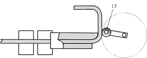
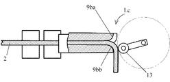
- FIG. 1 is a perspective view of a winding apparatus A according to the first embodiment.
- the wire supply means B is for sending or stopping and holding the coil wire 2 having a flat cross section, and for sending the coil wire 2 wound around a bobbin (not shown) in the direction of arrow J in the figure. It is.
- the wire supply means B is provided with two sets of drive mechanisms in which a motor and a drive roller are combined. That is, a first drive mechanism that sandwiches the coil wire 2 between the first motor 3 and the first drive roller 4 that transmits the rotation of the first motor 3 and the first drive roller 4 and the first passive roller 5 that passively rotates.
- a second drive mechanism that sandwiches the coil wire 2 by the second motor 6, the second drive roller 7, and the second passive roller 8 that passively rotates, and the drive roller and the passive roller are respectively indicated by arrows K 1.
- the coil wire 2 is sent out by rotating in the directions of arrows K2, K3, and K4.
- the coil wire 2 is first fed by the first drive roller 4 and the first passive roller 5, guided by the wire guide 9a, and further driven by the second drive roller 7 and the second passive roller 8 to reach the wire guide 9b.
- a bending guide 9ba is provided at the end of the wire guide 9b as described later. Further, the coil wire 2 is gripped by stopping the rotation of each motor.
- Each motor can be provided with a speed reducer to make the rotation speed appropriate, and has a control device (not shown) for starting and stopping the rotation of the motor.
- a control device not shown
- the motor A linear motion conversion mechanism using a screw and a screw may be used.
- the bending means C is provided with a bending pressing body 13 via a lever 12 on a rotating shaft 11 of a bending motor 10 which is a rotating mechanism, and rotates (revolves) in an arrow L direction (clockwise).
- the coil wire 2 is bent upward (counterclockwise) with the bending guide 9ba, which will be described later, in contact as a fulcrum.
- the distal end of the bending pressing body 13 is circular, and is bent while smoothly rotating on the coil wire 2 at the time of bending.
- the bending press body 13 shows the structure which bends the coil wire 2 while rotating like a roller which is free to rotate with respect to the lever 12, the bending press body 1 is fixed to the lever 12 and is coiled while sliding. The structure which bends the wire 2 may be sufficient.
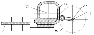
- the coil 14 is formed as shown in FIG. 2 by bending the coil wire 2 by the bending means C rotating several times.
- the lamination direction of the coil 14 is opposite to the direction in which the bending motor 10 is installed as shown in FIG.
- the center line of the coil at the position where the bending of the coil wire 2 by the bending pressing body 13 of the bending means C is completed is Z1
- the center line of the rotating shaft 11 of the bending pressing body 12 of the bending means C is Z2
- the center line Z2 is located away from the center line Z1 of the coil 14, and the coil wire 2 is positioned outside the outer peripheral surface of the coil 14 at a position after bending.
- the bending motor 10 may drive the rotary shaft 11 from a position separated by driving a belt or the like.
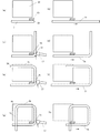
- FIGS. 3 to 10 are views from the XX direction shown in FIG.
- FIG. 3 shows step 1 and shows a state before the coil wire 2 starts winding, the rotating shaft 11 and the bending pressing body 13 are stopped, and the coil wire 2 is moved in the direction of arrow J. It is fed from the wire guide 9b.
- a circular two-dot chain line indicates a rotation locus of the bending pressing body 13.
- the feeding length of the coil wire 2 is controlled by the number of rotations and the rotation angle of the motor of the wire supply means B.
- the bending pressing body 13 rotating in the direction of the arrow L approaches the coil wire 2 and the bending pressing body 13 comes into contact with the coil wire 2, and the coil wire 2 Bending is started around the curved bending guide 9ba at the end of the wire guide 9b.
- FIG. 5 shows Step 3 and shows a state in which the coil wire 2 is bent at approximately 90 degrees through the curved portion 2a.
- the bending pressing body 13 is rotated clockwise and moved to the most leftmost position, and the coil wire 2 is rotated about 90 degrees counterclockwise or 90 degrees in consideration of the effect of springback in some cases. Bend deeply into the following acute angles.
- the bending pressing body 13 further rotates, bends the coil wire 2, and gradually moves away from the coil wire 2. 4 to 6, the coil wire 2 does not move and maintains its position.
- the supply of the coil wire 2 is thereafter performed by the wire supply means B. Is started.
- the bending pressing body 13 also continues to rotate, and the bending pressing body 13 moves faster, so that the linear portion 2b of the coil wire 2 contacts the bending pressing body 13 as shown in FIG. There is no.
- the timing which sends the coil wire 2 may be made after the bending press body 13 leaves
- a sensor for detecting the rotational position of the bending pressing body may be provided.
- the wire supply means B stops sending and holding the coil wire 2 as shown in step 5 of FIG.
- the bending pressing body 13 continues to rotate and approaches the coil wire 2. At this time, since the driving load applied to the bending pressing body 13 is small, the speed can be increased to save time. In particular, useless time can be eliminated when one side of the rectangular shape is short.
- FIG. 8 shows step 6 in which the bending pressing body 13 abuts on the coil wire 2 and bending is started around the end 9ba of the bending guide 9b, and the second bending is completed in step 7 of FIG. To do.
- bending is performed by decreasing the rotational speed and increasing the motor torque.
- the coil wire 2 is fed by the length of the other side of the rectangular coil, and the third bending process is performed in step 8 of FIG.
- rectangular coils 14 stacked as shown in FIG. 2 are manufactured.
- the coil wire 2 is bent by the bending pressing body 13 of the bending means C, and the center Z1 of the coil and the center Z2 of the rotating shaft 11 when the coil 14 is formed as shown in FIG. Z2 is located further outside the outer periphery of the coil 14. Further, the rotation locus W of the bending pressing body 13 does not intersect the outer periphery of the coil 14 at this position.
- the bending pressing body 13 and the coil wire 2 are not in contact except during bending, and the bending pressing body 13 needs to be rotated in the reverse direction or moved in the coil stacking direction. You can see that there is no. Further, when the bending pressing body 13 is started, the bending motor 10 can be controlled easily and can be rotated at high speed because the bending motor 10 can be continuously rotated in one direction without moving the central axis in the axial direction. is there.
- an induction motor, a synchronous motor, a stepping motor or the like generally called a servo motor is used, and if a position detector that detects the rotational position of the bending pressing body 13 is provided, higher-precision control is possible. Become.
- a rectangular laminated coil that is close to a square made up of four bent portions and a straight non-bent portion connecting between the bent portions is shown.
- the wire rod It can be applied by adjusting the feed amount of the supply means B.
- a quadrangular laminated coil composed of four bent portions and a linear portion communicating between them, but also other polygonal coils can be applied.
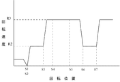
- FIG. 1 An example of the rotation speed control of the bending pressing body 13 is shown by a graph in FIG.
- the horizontal axis indicates the rotational position of the bending pressing body 13, and the vertical axis indicates the rotational speed of the bending pressing body 13.
- the bending pressing body 13 is stationary at the initial position S1 point of Step 1 in FIG. 3 and the coil wire 2 is supplied, and the bending pressing body 13 starts rotating from the S2 point (Step 2 in FIG. 4). Since the load is large due to the bending, the rotation speed is decreased (rotation speed R2) and the driving torque of the bending motor 10 is increased to perform bending.
- Point S3 is the state of step 3 in FIG.
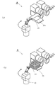
- FIG. 12 to 13 are perspective views showing the configuration of the second embodiment of the present invention.
- the difference from the first embodiment is that the direction of the entire winding device A is changed.
- the coil 14 is rotated and bent horizontally with respect to gravity, and the coil 14 is laminated in the direction of gravity.
- FIG. 13A there is a coil support 20 that supports the coil 14 that is bent, and an inclined guide 20 a is provided on a part of the coil support 20.
- FIG. 13B the coil 14 is bent and guided on the inclined guide 20 a and laminated on the coil support 20.
- the bending motor 10 is installed in a direction opposite to the direction in which the coils 14 are laminated (downward in FIG. 13), and prevents the bending motor 10 from being contacted by the lamination of the coils 14.
- FIG. 14 is a perspective view showing the configuration of the third embodiment of the present invention.
- the difference from the first embodiment is that a position changing means D in the horizontal direction is provided.
- the position changing means D comprises a moving motor 15, a linear conversion mechanism 16 and a drive shaft 17, and converts the rotational motion of the mobile motor 15 into a linear motion by a linear conversion mechanism 16 constituted by a screw mechanism. Is driven in the direction indicated by arrow N.
- the drive shaft 17 can be moved in contact with the table 18 and the bending means C fixed to the table 18 can be moved.
- the other position changing means E is moved at right angles to the moving direction of the position changing means D, and can be moved in two dimensions by two position changing means, and a moving device (not shown) that moves vertically.
- the bending angle can be adjusted by the movement of the bending means C.
- the bending angle can be adjusted by changing the position of the bending pressing body 13 in the state of step 3 in FIG.
- the table 18 is moved to the bending guide 9b side by the position changing means D, the bending amount is increased and the table 18 is bent at an acute angle.
- the position changing means D is operated to move the bending pressing body 13 and bend it at an acute angle as shown in the coil wire 2c.
- FIG. 16 shows a schematic diagram of the operation of the fourth embodiment of the present invention.
- the difference from the first embodiment is that a plurality of bending pressing bodies are provided. That is, apart from the bending pressing body 13 attached to the rotating shaft 11 via the lever 12, the bending pressing body 13a is provided symmetrically with respect to the rotating shaft 11 via the lever 12a.
- two bending pressing bodies it is possible to bend twice by one rotation of the rotating shaft 11 and to reduce the coil manufacturing time even if the rotating shaft is at a low speed.
- the case where two bending pressing bodies are used is shown, but three or more bending pressing bodies are also possible.
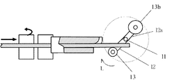
- FIG. 17 shows a schematic diagram of the operation of the fifth embodiment of the present invention.
- the difference from the fourth embodiment is that two bending pressing bodies 13 and 13b having different sizes are provided.
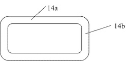
- the ratio of the long side 14a and the short side 14b is greatly different in a rectangular coil as shown in FIG. 18, the amount of springback generated during bending is different, and the coil shape may be distorted. .
- the bending pressing body 13b having a size different from that of the bending pressing body 13 can be provided to reduce the influence of the spring back, and an accurate dimension can be obtained even in a rectangular coil having different long sides and short sides.
- the coil can be manufactured.
- the position of the bending pressing body 13b in the rotational direction is 180 degrees with respect to the bending pressing body 13 in the embodiment, but can be changed to an appropriate position depending on the shape of the rectangular coil.
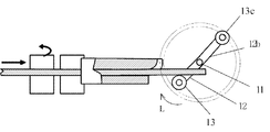
- FIG. 19 shows a schematic diagram of the operation of the sixth embodiment of the present invention.
- the difference from the fifth embodiment is that two bending pressing bodies having different rotation radii are provided.
- the bending pressing body 13 c is attached to the bending pressing body 13 attached to the lever 12 and the lever 12 b having a longer radius than the lever 12.
- the bending pressing body 13 bends the coil wire 2 and then further bends to a more acute angle by the bending pressing body 13c, so that dimensional accuracy can be maintained even when the springback is large.
- the position of the bending pressing body 13c in the rotation direction is 180 degrees with respect to the bending pressing body 13 in the embodiment, but can be changed depending on the shape of the rectangular coil.
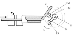
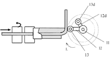
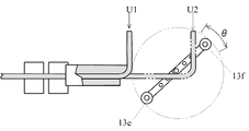
- FIG. 20 and 21 are schematic diagrams showing the operation of the seventh embodiment of the present invention.
- the bending pressing body 13d apart from the bending pressing body 13, the bending pressing body 13d is provided on a lever 12d having a small rotation radius.
- the bending pressing body 13d bends the coil wire 2 at a predetermined angle, and then the bending pressing body 13 bends the coil wire 2 by 90 degrees as shown in FIG.
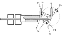
- FIG. 22 is a schematic diagram showing the operation
- FIG. 23 is a block diagram of the bending position detecting means
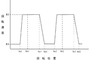
- FIG. 24 is a graph showing the rotational speed of the bending pressing body 13.
- the bending motor 10 increases the rotational speed from the position Sa where the bending pressing body 13 has finished bending the coil wire 2, and when reaching the position Sb, the coil wire 2 is sent from the position U 1 to the position U 2. It is done.
- the bending pressing body 13 further rotates and reaches the position Sc before the bending pressing body 13 bends the coil wire 2, the bending pressing body 13 is detected by the bending position detecting means 19 as shown in FIG.
- the bending motor 10 decelerates and reaches the position Sd where the bending pressing body 13 contacts the coil wire 2 in a state where the rotational speed of the bending pressing body 13 is reduced.
- the bending pressing body 13 touches softly without damaging the surface of the coil wire 2, and thereafter bends the coil wire 2 at a low speed.
- the generated torque is large, and the bending motor 10 can rotate with a sufficient margin during bending with a large load.
- the bending position detection means 19 may be a reflection type optical sensor, a metal proximity sensor, or the like in addition to the transmission type optical sensor as shown in the embodiment.
- the rotational position Sa1 indicates the state of the rotational position Sa in FIG. 22, and the rotational speed is the low speed R4. Since the coil wire 2 has already been bent at this position, the rotational speed is increased to R5.
- the bending pressing body 13 passes through the position of Sb in FIG. 22 (Sb1 in FIG. 24) at high speed, and continues to rotate at a high speed even after the coil wire 2 is sent and reaches the position of Sc as described above.
- the position is detected by the means 19, and the rotation speed is decelerated from R5 (rotation position Sc1) to R4 (rotation position Sd). Thereafter, this operation is repeated to stack the nonlinear coils.
- the positions Sa and Sb can be determined from the rotational speed of the bending motor 10 according to time, but may be detected using a position detection sensor. Further, the bending position detecting means 19 can count the number of times the coil wire 2 is bent, and can detect a predetermined number of times of bending, that is, the number of laminated coils.
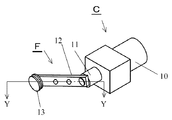
- FIG. 25 is a perspective view showing the configuration of the ninth embodiment.
- the turning radius changing means F is changed by changing the attachment position of the lever 12 attached to the rotating shaft 11 of the bending means C and changing the length of the lever 12 to act.
- Form. 26 is a cross-sectional view taken along the line YY of FIG. 25.
- the lever 12 is provided with a plurality of mounting holes 12a, 12b, and 12c, and the rotation radius can be changed depending on the mounting position on the rotary shaft 11.
- FIG. 26 and FIG. 27 show a state in which the rotation radius is attached to the hole 12a which is the longest position.
- the rotation radius By increasing the rotation radius, it is possible to perform a bending process at a high speed by providing a plurality of bending pressing bodies 13 even for a large coil shape as shown in FIG. Even if one side of the coil wire 2 is lengthened from the position U1 to the position U3, the bending pressing bodies 13e and 13f can be provided to be opposed to each other by 180 degrees, so that the number of bendings per rotation can be made twice. That is, the bending pressing body 13f can send the wire coil 2 to the position U3. At this time, the bending motor 13e has not yet reached the bending position. If the coil wire 2 can be sent from U1 to U3 between the angles ⁇ in the figure, it can be bent continuously, and the winding speed of the coil increases.
- the position of the fulcrum is set to the position of the hole 12c, and the bending pressing body 13 is rotated with a small turning radius. If the generated torque of the bending motor is the same, the force acting on the bending pressing body 13 at this time becomes large, and processing can be performed even with a coil with a small curvature radius or a coil wire with a high hardness material.
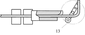
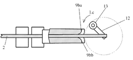
- FIG. 29 and FIG. 30 are operation schematic diagrams showing Embodiment 10 of the present invention.
- a wire rod guide 9bb is provided oppositely, the rotation direction of the bending pressing body is rotated in the counterclockwise Lc direction opposite to the conventional one, and the coil wire 2 as shown in FIG. Is bent downward in the figure.
- the coil support 20 shown in FIG. 1 is also provided in the opposite direction to FIG. It is also possible to create a parallel type coil by initially rotating the bending pressing body 13 clockwise and then rotating it counterclockwise from the middle.
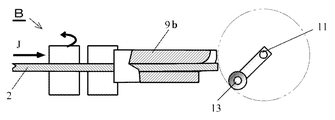
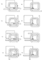
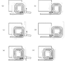
- FIGS. 31 to 36 show an eleventh embodiment of the present invention, in which a rectangular coil of 7.6 mm ⁇ 2 mm is wound edgewise, and the operation of a rectangular spiral coil having an outermost circumference of 84 mm ⁇ 84 mm and an innermost circumference of 28 mm ⁇ 28 mm is shown. It is a schematic diagram.
- a specific dimension is an example, Comprising: This invention is not limited to this dimension. The process of winding from a coil with a large circumference as a first winding process and winding a coil with a small circumference in order will be described.
- FIG. 31A shows the state of the initial position before winding the coil, and the coil wire 2 is sent out from the end 2d along the wire guide 9b by the wire supply means B (FIG. 1).
- Reference numeral 20 denotes a coil support as coil moving means.
- the coil wire 2 stops when it is fed a predetermined length (straight line portion 2e), and the bending roller 13 rotates and the bent portion 2f of the coil wire 2 rotates as shown in FIG. 31 (c).
- the first bend is performed along the wire guide 9b at the portion.
- the terminal is taken out in this first bending, for example, in the case of a rectangular coil having a length of one side of the outermost periphery of 84 mm, it is set to be slightly longer, for example, about 110 mm.
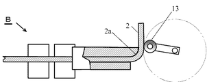
- the coil wire 2 is sent by the wire rod supply means B in the direction of the arrow, for example, 60 mm (straight line portion 2g), and stopped.
- the bending roller 13 continues to rotate during this time, and as shown in FIG. 31E, after the coil wire 2 completes feeding, the second bending is performed again at the bending portion 2h. At this time, the coil wire rod tip 2d and the straight line portion 2e run on the coil support 20 and rotate while being guided.
- the coil wire 2 Since the straight portion 2h is guided by the guide surface 20a (see FIG. 13) of the coil support 20, the coil wire 2 is deformed by moving in a direction perpendicular to the bending coil surface.
- the inclination of the coil support 20 is set so that the deformation amount is equal to or less than the elastic limit of 2.
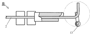
- the coil wire 2 is sent to the same length (60 mm) of the straight portion 2g as the second delivery (FIG. 31 (d)) as the third delivery.
- the bending roller 13 performs bending at the bent portion 2j.
- the wire from the straight portion 2e to the straight portion 2g is guided by the coil support 20 and rotates.
- the linear portion 2e is guided to the outside of the wire rod guide 9b (FIG. 3) by the coil support 20 and intersects the coil wire rod 2 passing through the inside of the wire rod guide 9b in three dimensions, so that they do not interfere with each other.
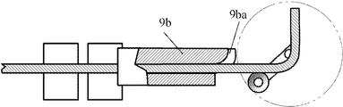
- the wire coil 2 is sent out shorter than the third feed amount 60mm than the width of the coil wire 2 (7.6 mm in this embodiment), for example, the length of the straight portion 2k.
- the length is set to 52 mm, and the fourth feeding is performed.
- the fourth bending is performed at the bending portion 2m. Since the straight portion 2e is guided to the outside of the wire guide 9b as described above, it intersects the supplied coil wire 2 three-dimensionally.
- the fifth delivery of the coil wire 2 is set to the same length as the fourth as shown in FIG. 32 (b), and the bent portion 2p is bent as shown in FIG. 32 (c).
- the bent portion 2g is guided to the outside of the wire guide 9b, the bent portion 2e and the bending roller 13 do not interfere with each other, and the fifth turn is performed at the bent portion 2p.
- the sixth delivery is made shorter than the fifth delivery amount of 52 mm and shorter than the width of the coil wire 2 and the length of the straight portion 2q is set to 44 mm, for example.
- a sixth turn is performed by the bent portion 2r.
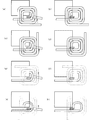
- the seventh time (FIGS. 32 (f) and 32 (g)) is 44 mm
- the eighth time (FIGS. 32 (h) and 33 (a)) and the ninth time (FIG. 33 (b) and FIG. 33 (c)) is the delivery amount 36 mm
- the 10th time (FIGS. 33 (d) and 33 (e)) and the 11th time (FIGS. 33 (f) and 33 (g)) are the delivery amount 28mm
- the 13th time (FIG. 34 (b) and FIG. 8 (c)) are the winding and bending of the coil wire 2 having a feed amount of 20 mm.
- a rectangular spiral coil is formed from the larger circumference to the smaller circumference.
- the coil wire of the practical part is described with a small width so that it does not overlap with the broken line, but since it is actually one wire with the same diameter, the width of the wire is the same as in the first step .
- the 16th time (FIGS. 34 (h) and 35 (a)) and the 17th time (FIGS. 35 (b) and 35 (c)) are the delivery amount 28 mm, and the 18th time (FIGS. 35 (d) and 35 (e)).
- ) And 19th time (FIGS. 35 (f) and 35 (g) show a delivery amount of 36 mm, and 20th time (FIGS. 35 (h), 36 (a) and 21st times (FIGS. 36 (b) and 36)).
- Feeding amount 44 mm, 22nd time (FIGS. 36D and 36E are sent and bent at a feeding amount of 52 mm, and the coil wire 2 is cut and as shown in FIG. 36F.
- a rectangular spiral coil that overlaps two layers (a part is one layer) is formed.
- the first winding step and the second winding step constitute one winding unit, and the connection terminal can be taken out from the outermost periphery.
- the connection terminal can be taken out from the outermost periphery.
- a coil laminated in three or more layers can be manufactured.
- the bending roller 13 is continuously rotated, the coil wire 2 is continuously supplied, and the coil wire can be cut halfway or wound from the other end. There is no so-called one-stroke writing.
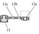
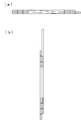
- FIG. 37 and 38 show a spiral coil produced by the manufacturing method of Example 11.
- FIG. 37 (a) is a front view
- (b) is a rear view
- (c) is a right side view
- (d) is a left side view
- (e) is a plan view
- (f) is a bottom view
- FIG. (A) and (b) of FIG. 37 are an AA sectional view and a BB sectional view, respectively, shown in the front view of FIG.
- the rectangular spiral coil shown in FIG. 37 has a maximum of four turns formed in two layers. The coil already wound when the coil wire 2 is bent is guided by the coil support 20 and deformed in a direction perpendicular to the surface around which the coil is wound.
- the size of the coil support guide 20 needs to be selected to an optimum value depending on the elastic coefficient of the coil wire, the winding length of the coil, etc. If it is the size shown in Example 11 with the copper wire rod obtained, there will be no problem in particular and manufacture is possible.
- the coil wire is continuously wound from one end by providing a portion where the wire does not overlap in the winding unit on the innermost peripheral portion and the outermost peripheral portion of the spiral coil. Is possible.
- winding is started from one end 2a of the coil wire, wound from one having a large coil circumference to one having a small coil circumference, and continuously wound from one having a small coil circumference to one having a large coil circumference. Since it rotates, the outermost periphery and innermost periphery of a coil are comprised so that the number of turns may decrease. That is, many are wound in two layers, but by providing one layer portion on the innermost and outermost circumferences, it is possible to manufacture by winding continuously from the end 2a of the coil wire in the same direction. it can. Since one side of the non-linear coil is shortened in the inner peripheral portion of the spiral, it is conceivable that the amount of coil movement exceeds the elastic limit. However, slight deformation is acceptable as long as it is within an allowable range for thin dimensions. Particularly in the innermost circumference, there is a portion where there is no overlap in one turn unit, so that the thin dimensions can be maintained.
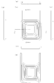
- 39 and 40 show a coil of Example 12 of the present invention.
- the difference from Example 11 is that the coil wire is round.
- 39 (a) is a front view
- (b) is a rear view
- (c) is a right side view
- (d) is a left side view
- (e) is a plan view
- (f) is a bottom view.
- (A) and (b) are a CC sectional view and a DD sectional view, respectively, shown in the front view of FIG. 39 (a).
- the coil by a round wire has the fault that a coil size will become large when an electric current density is equivalent, since it is a coil wire material generally manufactured, there exists an advantage which can manufacture a coil at low cost.
Abstract
In order to obtain a device that has a simple configuration and that rapidly winds a non-circular coil such as a rectangular coil, this winding device is equipped with: a wire material supply means that feeds and grips a coil wire material; a bending guide provided on a portion of the wire material supply means; and a bending means that causes the coil wire material to make contact with the bending guide, thereby bending the coil wire material. The bending means has a center of rotation at a position on the outside of the coil after the coil wire material has been bent, and repeatedly rotates in one direction, and the feeding of the coil wire material by the wire material supply means causes the rotating bending means to make contact with the bending guide, thereby manufacturing a non-circular coil. Therefore, a non-circular coil can be manufactured rapidly by repeatedly rotating the bending means without moving the bending means in the stacking direction of the coil.
Description
本発明は、非円形コイルの巻線装置に関するものである。
The present invention relates to a winding device for non-circular coils.
近年、回転機の小型化と高性能化のため、断面が平角の線材を用いて、エッジワイズ法と称する巻線方法により長方形に近い非円形の形状に巻回することが行われている。エッジワイズ法は平角線を縦方向に巻くことで薄型にできる利点を有するが、巻線工程が容易でないという欠点があった。
In recent years, in order to reduce the size and increase the performance of rotating machines, winding is performed in a non-circular shape close to a rectangle by a winding method called an edgewise method using a wire having a flat cross section. The edgewise method has an advantage that it can be thinned by winding a rectangular wire in the vertical direction, but has a disadvantage that the winding process is not easy.
特許文献1は平角線を矩形状コイルにする製造方法を示したもので、ローラ状部材を中心にして回転台を回転し、曲げガイドに沿って押圧して曲折する。その後回転台を逆回転させて曲げガイドを元の位置に戻し、コイルを所定長押し出し、さらに再度曲げガイドに沿って曲折させる。以上の工程を繰り返し矩形のコイルを製造するものである。
また特許文献2には、挟持シャフトの周囲に等間隔を維持したまま回動可能に形成された複数の曲げ治具による、エッジワイズ巻線装置が開示されている。 Patent Document 1 shows a manufacturing method in which a rectangular wire is formed into a rectangular coil. A rotating table is rotated around a roller-shaped member, and is bent by pressing along a bending guide. Thereafter, the turntable is rotated backward to return the bending guide to the original position, the coil is pushed out for a predetermined length, and further bent along the bending guide again. The rectangular coil is manufactured by repeating the above steps.
Further,Patent Document 2 discloses an edgewise winding device using a plurality of bending jigs formed so as to be rotatable around a sandwiching shaft while maintaining an equal interval.
また特許文献2には、挟持シャフトの周囲に等間隔を維持したまま回動可能に形成された複数の曲げ治具による、エッジワイズ巻線装置が開示されている。 Patent Document 1 shows a manufacturing method in which a rectangular wire is formed into a rectangular coil. A rotating table is rotated around a roller-shaped member, and is bent by pressing along a bending guide. Thereafter, the turntable is rotated backward to return the bending guide to the original position, the coil is pushed out for a predetermined length, and further bent along the bending guide again. The rectangular coil is manufactured by repeating the above steps.
Further,
特許文献1の巻線装置においては、線材を曲折後に回転台を逆回転させなければならず高速で巻回することが困難である。また特許文献2の巻線装置においては、曲げ治具を曲げ動作を行うたびにコイルの積層方向に進退させなければならず、複雑な構成となっていた。
In the winding apparatus of Patent Document 1, it is difficult to wind at high speed because the turntable must be rotated in reverse after bending the wire. Further, in the winding device of Patent Document 2, every time a bending jig is bent, the winding device has to be moved back and forth in the coil stacking direction, resulting in a complicated configuration.
本発明は、上述の課題を解決するもので、簡単な構成で矩形コイルを高速で巻回する装置を得ることを目的とする。
This invention solves the above-mentioned subject, and it aims at obtaining the apparatus which winds a rectangular coil at high speed with a simple structure.
本発明に係る巻線装置は、曲げ部と非曲げ部とを有する非円形コイルの巻線装置において、コイル線材を送出および把持する線材供給手段と、線材供給手段の一部に設けられた曲げガイドと、曲げガイドにコイル線材を当接させて曲折する曲げ手段とを備え、曲げ手段はコイル線材の曲折後の位置におけるコイルの外側に回転中心を有し一方向に回転を繰り返し、線材供給手段によってコイル線材を送出し、回転する曲げ手段を曲げガイドに当接させて非円形のコイルを製造するものである。
上記構成としてより具体的には、コイル線材の曲折後の位置におけるコイルの外周と、回転機構による曲げ手段の軌跡とが交わらないように回転させるものである。
また、本発明に係る巻線装置の回転機構の設置された方向と逆方向にコイルが積層されるものである。
また、本発明に係る巻線装置は曲げ手段が、コイル線材に当接してコイル線材を曲折させた後、コイル線材の曲折位置に再び戻って来るまでの間に、線材供給手段がコイル線材を曲折位置から所定長さを送出し継続してコイル線材を曲折するものである。 The winding device according to the present invention is a winding device for a non-circular coil having a bending portion and a non-bending portion, and a wire rod supplying means for feeding and gripping the coil wire rod, and a bending portion provided in a part of the wire rod supplying device. A guide and a bending means for bending the coil wire in contact with the bending guide, and the bending means has a center of rotation outside the coil at a position after the coil wire is bent and repeats rotation in one direction to supply the wire The coil wire is delivered by the means, and the rotating bending means is brought into contact with the bending guide to produce a non-circular coil.
More specifically, the configuration is such that the outer periphery of the coil at the position after the coil wire is bent and the locus of the bending means by the rotation mechanism do not intersect.
Further, the coils are laminated in the direction opposite to the direction in which the rotation mechanism of the winding device according to the present invention is installed.
Further, in the winding device according to the present invention, after the bending means abuts on the coil wire and bends the coil wire, the wire supply means does not return the coil wire until it returns to the bending position of the coil wire. The coil wire is bent continuously by sending a predetermined length from the bending position.
また、本発明に係る巻線装置の曲げ手段は、コイル線材の当接時には回転速度を低下又は停止させて曲げ加工を行うものである。
上記構成として具体的には、曲げ手段の位置を検出する曲げ位置検出手段を曲げ手段がコイル線材に当接する前の位置に設置し、曲げ手段が位置検出手段の位置に達したときに曲げ手段を減速させるものである。
また、本発明に係る巻線装置の曲げ手段の回転の中心位置を変更する位置変更手段を備え、曲げ角度の調節を行うものである。
上記構成として具体的には、曲げ手段によるコイル線材の曲折中に位置変更手段を動作させ、コイル線材をさらに鋭角に曲折するものである。 Further, the bending means of the winding device according to the present invention performs bending by lowering or stopping the rotation speed when the coil wire is in contact.
Specifically, the bending position detecting means for detecting the position of the bending means is installed at a position before the bending means comes into contact with the coil wire, and the bending means is moved when the bending means reaches the position of the position detecting means. Is to slow down.
Further, a position changing means for changing the center position of rotation of the bending means of the winding device according to the present invention is provided, and the bending angle is adjusted.
Specifically, the position changing means is operated during the bending of the coil wire by the bending means to further bend the coil wire at an acute angle.
また、本発明に係る巻線装置の線材供給手段は、コイル線材を挟持して送出する駆動機構と、駆動機構から送出されたコイル線材を案内する線材ガイドと、線材ガイドの端部に設けられた曲げガイドを備えたものである。
In addition, the wire rod supply means of the winding device according to the present invention is provided at a drive mechanism for sandwiching and feeding the coil wire rod, a wire rod guide for guiding the coil wire rod fed from the drive mechanism, and an end portion of the wire rod guide. A bending guide is provided.
また、本発明に係る巻線装置の曲げ手段は、コイル線材に当接しコイル線材を曲折させる複数個の曲げ押圧体を備えたもので、複数個の曲げ押圧体を順次コイル線材に当接させて曲折させ、曲げ手段の1回転で複数の曲げ加工を行うものである。
上記構成として具体的には、複数個の曲げ押圧体は、大きさまたは回転半径の少なくとも一方が異なっているもので、コイル形状に合わせて曲げ角度を変更するものである。
また、本発明に係る巻線装置は、曲げ手段が回転半径変更手段を備え、回転半径の大きさを変更してコイルサイズに応じて最適な曲げ加工を行うものである。
また、本発明に係る巻線装置は、回転機構の回転方向の切り換えが可能であり、回転機構の回転方向を切り換えることによって巻方向の異なるコイルを製作できるものである。
また本発明に係る巻線装置は、コイル線材の供給長さを変えながら曲げ手段による曲折を繰り返し行い、コイル周長の大きいコイルの内側にコイル周長の小さなコイルを挿入して非円形渦巻コイルを製造するものである。 Further, the bending means of the winding device according to the present invention includes a plurality of bending pressing bodies that contact the coil wire and bend the coil wire, and sequentially contact the plurality of bending pressing bodies to the coil wire. Are bent, and a plurality of bending processes are performed by one rotation of the bending means.
Specifically, the plurality of bending pressing bodies differ in at least one of the size and the radius of rotation, and change the bending angle in accordance with the coil shape.
Further, in the winding device according to the present invention, the bending means includes a turning radius changing means, and the bending radius is changed to perform an optimum bending process according to the coil size.
Moreover, the winding device according to the present invention can switch the rotation direction of the rotation mechanism, and can manufacture coils having different winding directions by switching the rotation direction of the rotation mechanism.
The winding device according to the present invention repeatedly performs bending by a bending means while changing the supply length of the coil wire, and inserts a coil having a small coil circumference inside a coil having a large coil circumference, thereby providing a non-circular spiral coil. Is to be manufactured.
本発明に係る巻線装置によれば、曲げガイドにコイル線材を当接させて曲折する曲げ手段を備え、曲げ手段はコイル線材が巻回して形成するコイルの外側に回転中心を有し一方向に回転を繰り返す構成としたので、簡単な構成で非円形のコイルを製造できる。また、曲げ手段を逆回転させたり、あるいは曲げ手段をコイルの積層方向に移動させる必要がなく、高速で非円形コイルを巻回することができ時間あたりの生産量が大きくなり、加工費の低減ができる。
According to the winding device of the present invention, the bending device is provided with a bending means for bending by bringing the coil wire into contact with the bending guide, and the bending means has a rotation center on the outer side of the coil formed by winding the coil wire, and is unidirectional. Therefore, a non-circular coil can be manufactured with a simple configuration. In addition, it is not necessary to reversely rotate the bending means or move the bending means in the coil stacking direction, and non-circular coils can be wound at a high speed, resulting in an increase in production per hour and reduction in processing costs. Can do.
本発明の実施形態について、実施例1から実施例12の各々を例に挙げ、図面を参照しながら以下に説明する。なお、本発明の内容はこれらの実施形態に何ら限定されるものではない。
Embodiments of the present invention will be described below with reference to the drawings, taking each of Examples 1 to 12 as examples. The contents of the present invention are not limited to these embodiments.
本発明の実施例1を図面に基づいて説明する。図1は、実施例1に係る巻線装置Aの斜視図である。線材供給手段Bは断面形状が平角であるコイル線材2を送出又は停止させて把持するものであり、ボビン(図示せず)に巻かれたコイル線材2を図の矢印Jの方向に送出するものである。線材供給手段Bは、モータと駆動ローラの組み合わせた駆動機構を2セット配している。すなわち第1モータ3と第1モータ3の回転を伝達する第1駆動ローラ4と、第1駆動ローラ4と受動的に回転する第1受動ローラ5とでコイル線材2を挟み込む第1の駆動機構と、第2モータ6と第2駆動ローラ7と、受動的に回転する第2受動ローラ8とによってもコイル線材2を挟み込む第2の駆動機構とがあり、駆動ローラと受動ローラをそれぞれ矢印K1、矢印K2、矢印K3、矢印K4の方向に回転させることによりコイル線材2を送出する。コイル線材2はまず第1駆動ローラ4と第1受動ローラ5とにより送られ、線材ガイド9aで案内され、第2駆動ローラ7と第2受動ローラ8でさらに駆動されて線材ガイド9bに達する。線材ガイド9bの端部には後述するように曲げガイド9baが設けられている。また各モータの回転を停止することでコイル線材2を把持する。
それぞれのモータは、回転数を適正にするために減速器を備えることができ、またモータの回転を発停する制御装置(図示せず)を有する。
なお、第1モータ3と第1駆動ローラ4と第1受動ローラとの組み合わせ、あるいは第2モータ6と第2駆動ローラ7と第2受動ローラ8との組み合わせによる線材供給手段の代わりに、モータとねじによる直線運動変換機構を用いても良い。 A first embodiment of the present invention will be described with reference to the drawings. FIG. 1 is a perspective view of a winding apparatus A according to the first embodiment. The wire supply means B is for sending or stopping and holding thecoil wire 2 having a flat cross section, and for sending the coil wire 2 wound around a bobbin (not shown) in the direction of arrow J in the figure. It is. The wire supply means B is provided with two sets of drive mechanisms in which a motor and a drive roller are combined. That is, a first drive mechanism that sandwiches the coil wire 2 between the first motor 3 and the first drive roller 4 that transmits the rotation of the first motor 3 and the first drive roller 4 and the first passive roller 5 that passively rotates. And a second drive mechanism that sandwiches the coil wire 2 by the second motor 6, the second drive roller 7, and the second passive roller 8 that passively rotates, and the drive roller and the passive roller are respectively indicated by arrows K 1. The coil wire 2 is sent out by rotating in the directions of arrows K2, K3, and K4. The coil wire 2 is first fed by the first drive roller 4 and the first passive roller 5, guided by the wire guide 9a, and further driven by the second drive roller 7 and the second passive roller 8 to reach the wire guide 9b. A bending guide 9ba is provided at the end of the wire guide 9b as described later. Further, the coil wire 2 is gripped by stopping the rotation of each motor.
Each motor can be provided with a speed reducer to make the rotation speed appropriate, and has a control device (not shown) for starting and stopping the rotation of the motor.
Instead of the wire supply means by the combination of the first motor 3, thefirst drive roller 4, and the first passive roller, or the combination of the second motor 6, the second drive roller 7, and the second passive roller 8, the motor A linear motion conversion mechanism using a screw and a screw may be used.
それぞれのモータは、回転数を適正にするために減速器を備えることができ、またモータの回転を発停する制御装置(図示せず)を有する。
なお、第1モータ3と第1駆動ローラ4と第1受動ローラとの組み合わせ、あるいは第2モータ6と第2駆動ローラ7と第2受動ローラ8との組み合わせによる線材供給手段の代わりに、モータとねじによる直線運動変換機構を用いても良い。 A first embodiment of the present invention will be described with reference to the drawings. FIG. 1 is a perspective view of a winding apparatus A according to the first embodiment. The wire supply means B is for sending or stopping and holding the
Each motor can be provided with a speed reducer to make the rotation speed appropriate, and has a control device (not shown) for starting and stopping the rotation of the motor.
Instead of the wire supply means by the combination of the first motor 3, the
曲げ手段Cは回転機構である曲げモータ10の回転軸11にレバー12を介して曲げ押圧体13を備え、矢印L方向(時計方向)に回転(公転)し、図1においてはコイル線材2に当接して後述する曲げガイド9baを支点としてコイル線材2を図の上方向(反時計方向)に折り曲げる。曲げ押圧体13の先端は円形になっており折り曲げの際にはなめらかにコイル線材2上を自転しながら折り曲げを行う。なお、曲げ押圧体13はレバー12に対して回転自由なローラのようなもので回転しながらコイル線材2を曲折する構成を示しているが、曲げ押圧体1をレバー12に固定し滑りながらコイル線材2を曲折する構造でも良い。
The bending means C is provided with a bending pressing body 13 via a lever 12 on a rotating shaft 11 of a bending motor 10 which is a rotating mechanism, and rotates (revolves) in an arrow L direction (clockwise). In FIG. The coil wire 2 is bent upward (counterclockwise) with the bending guide 9ba, which will be described later, in contact as a fulcrum. The distal end of the bending pressing body 13 is circular, and is bent while smoothly rotating on the coil wire 2 at the time of bending. In addition, although the bending press body 13 shows the structure which bends the coil wire 2 while rotating like a roller which is free to rotate with respect to the lever 12, the bending press body 1 is fixed to the lever 12 and is coiled while sliding. The structure which bends the wire 2 may be sufficient.
曲げ手段Cが幾度か回転してコイル線材2を折り曲げることによって図2に示すようにコイル14を形成する。コイル14の積層方向は図2に示すように曲げモータ10設置方向と反対方向である。曲げ手段Cの曲げ押圧体13によるコイル線材2の曲折が完了した位置でのコイルの中心線をZ1とし、曲げ手段Cの曲げ押圧体12の回転軸11の中心線をZ2とすると、中心線Z2はコイル14の中心線Z1とは離れた位置にあり、コイル線材2を曲折後の位置においてコイル14の外周面よりも外側に位置している。なお、曲げモータ10はベルトなどの駆動により離れた位置から回転軸11を駆動しても良い。
The coil 14 is formed as shown in FIG. 2 by bending the coil wire 2 by the bending means C rotating several times. The lamination direction of the coil 14 is opposite to the direction in which the bending motor 10 is installed as shown in FIG. When the center line of the coil at the position where the bending of the coil wire 2 by the bending pressing body 13 of the bending means C is completed is Z1, and the center line of the rotating shaft 11 of the bending pressing body 12 of the bending means C is Z2, the center line Z2 is located away from the center line Z1 of the coil 14, and the coil wire 2 is positioned outside the outer peripheral surface of the coil 14 at a position after bending. The bending motor 10 may drive the rotary shaft 11 from a position separated by driving a belt or the like.
本発明の巻線装置の巻回の過程を矩形コイルの製作を例にして、図3~図10に動作の模式図にて示す。なお、図3から図10の図面は図1に示すX-X方向からの図である。図3はステップ1を示したもので、コイル線材2が巻回を始める前の状態を示しており、回転軸11と曲げ押圧体13は停止しており、コイル線材2は矢印Jの方向に送られ線材ガイド9bから突出する。なお円形の2点鎖線は曲げ押圧体13の回転軌跡を示す。さらにコイル線材2が送られて、図4のステップ2に示すように所定の長さに到達すると、線材供給手段Bは回転を停止し、コイル線材2を把持する。このコイル線材2の送出長さの制御は線材供給手段Bのモータの回転数や回転角度で行われる。コイル線材2が所定長さ送られて把持されると、矢印L方向に回転している曲げ押圧体13がコイル線材2に接近してコイル線材2に曲げ押圧体13が当接し、コイル線材2を線材ガイド9bの端部にある曲面形状の曲げガイド9baを中心に折り曲げを開始する。
The winding process of the winding device of the present invention is shown in FIGS. 3 to 10 as schematic diagrams of operations, taking the production of a rectangular coil as an example. 3 to 10 are views from the XX direction shown in FIG. FIG. 3 shows step 1 and shows a state before the coil wire 2 starts winding, the rotating shaft 11 and the bending pressing body 13 are stopped, and the coil wire 2 is moved in the direction of arrow J. It is fed from the wire guide 9b. A circular two-dot chain line indicates a rotation locus of the bending pressing body 13. When the coil wire 2 is further sent and reaches a predetermined length as shown in Step 2 of FIG. 4, the wire supply means B stops rotating and grips the coil wire 2. The feeding length of the coil wire 2 is controlled by the number of rotations and the rotation angle of the motor of the wire supply means B. When the coil wire 2 is fed by a predetermined length and gripped, the bending pressing body 13 rotating in the direction of the arrow L approaches the coil wire 2 and the bending pressing body 13 comes into contact with the coil wire 2, and the coil wire 2 Bending is started around the curved bending guide 9ba at the end of the wire guide 9b.
図5はステップ3を示し、コイル線材2が曲線部2aを経てほぼ90度に折り曲げられた状態を示している。この状態で曲げ押圧体13は時計方向に回転しほぼ最も左端の位置に移動した状態にあり、コイル線材2を反時計方向に約90度あるいは場合によってはスプリングバックの影響を考慮して90度以下の鋭角に深く曲げる。図6のステップ4では曲げ押圧体13がさらに回転し、コイル線材2を折り曲げた後、コイル線材2よりしだいに離れていく。図4から図6までの間コイル線材2は移動せずにその位置を保っているが、曲げ押圧体13がコイル線材2から離れていくと、この後線材供給手段Bによってコイル線材2の供給が開始される。このとき曲げ押圧体13も回転を継続しており、曲げ押圧体13の移動の方が速く行われるので、図6に示すようにコイル線材2の直線部2bが曲げ押圧体13に接触することはない。なお、コイル線材2を送出するタイミングは安全を期すなら、曲げ押圧体13が相当の距離離れてから行わせてもよい。コイル線材2の送出に関するより正確なタイミングを得るために、曲げ押圧体の回転位置を検出するセンサを設けても良い。
次に矩形コイルの一辺の長さ分だけコイル線材2が送出されると図7のステップ5に示すように線材供給手段Bはコイル線材2の送出を停止し把持する。曲げ押圧体13は継続して回転を行っておりコイル線材2に近づいていく。このとき曲げ押圧体13にかかる駆動負荷は小さいので速度を上げて時間を節約することが可能である。特に矩形形状の一辺が短いときに無駄な時間をなくすことができる。 FIG. 5 shows Step 3 and shows a state in which thecoil wire 2 is bent at approximately 90 degrees through the curved portion 2a. In this state, the bending pressing body 13 is rotated clockwise and moved to the most leftmost position, and the coil wire 2 is rotated about 90 degrees counterclockwise or 90 degrees in consideration of the effect of springback in some cases. Bend deeply into the following acute angles. In step 4 of FIG. 6, the bending pressing body 13 further rotates, bends the coil wire 2, and gradually moves away from the coil wire 2. 4 to 6, the coil wire 2 does not move and maintains its position. However, when the bending pressing body 13 moves away from the coil wire 2, the supply of the coil wire 2 is thereafter performed by the wire supply means B. Is started. At this time, the bending pressing body 13 also continues to rotate, and the bending pressing body 13 moves faster, so that the linear portion 2b of the coil wire 2 contacts the bending pressing body 13 as shown in FIG. There is no. In addition, the timing which sends the coil wire 2 may be made after the bending press body 13 leaves | separates a considerable distance, if it is taken care of safety. In order to obtain more accurate timing related to the delivery of the coil wire 2, a sensor for detecting the rotational position of the bending pressing body may be provided.
Next, when thecoil wire 2 is sent out by the length of one side of the rectangular coil, the wire supply means B stops sending and holding the coil wire 2 as shown in step 5 of FIG. The bending pressing body 13 continues to rotate and approaches the coil wire 2. At this time, since the driving load applied to the bending pressing body 13 is small, the speed can be increased to save time. In particular, useless time can be eliminated when one side of the rectangular shape is short.
次に矩形コイルの一辺の長さ分だけコイル線材2が送出されると図7のステップ5に示すように線材供給手段Bはコイル線材2の送出を停止し把持する。曲げ押圧体13は継続して回転を行っておりコイル線材2に近づいていく。このとき曲げ押圧体13にかかる駆動負荷は小さいので速度を上げて時間を節約することが可能である。特に矩形形状の一辺が短いときに無駄な時間をなくすことができる。 FIG. 5 shows Step 3 and shows a state in which the
Next, when the
図8はステップ6を示しており、曲げ押圧体13がコイル線材2に当接し曲げガイド9bの端部9baを中心として曲げ加工が開始され、図9のステップ7で2回目の曲げ加工が完了する。このときは曲げ押圧体13には比較的大きな負荷がかかるので回転速度を下げてモータトルクを上げて曲げ加工を行う。さらに同様の動作によりコイル線材2が矩形コイルの他の一辺の長さの分だけ送られ、図10のステップ8で3回目の曲げ加工が行われる。以上の動作を繰り返すことにより図2に示すように積層された矩形のコイル14が製造される。
曲げ手段Cの曲げ押圧体13によってコイル線材2の曲げ加工が行われ、図2に示すようにコイル14が形成されたときのコイルの中心Z1と回転軸11の中心Z2とは位置が異なっており、Z2はコイル14の外周よりもさらに外側に位置している。また曲げ押圧体13の回転軌跡Wはこの位置でのコイル14の外周と交わることがない。 FIG. 8 shows step 6 in which thebending pressing body 13 abuts on the coil wire 2 and bending is started around the end 9ba of the bending guide 9b, and the second bending is completed in step 7 of FIG. To do. At this time, since a relatively large load is applied to the bending pressing body 13, bending is performed by decreasing the rotational speed and increasing the motor torque. Further, by the same operation, the coil wire 2 is fed by the length of the other side of the rectangular coil, and the third bending process is performed in step 8 of FIG. By repeating the above operation, rectangular coils 14 stacked as shown in FIG. 2 are manufactured.
Thecoil wire 2 is bent by the bending pressing body 13 of the bending means C, and the center Z1 of the coil and the center Z2 of the rotating shaft 11 when the coil 14 is formed as shown in FIG. Z2 is located further outside the outer periphery of the coil 14. Further, the rotation locus W of the bending pressing body 13 does not intersect the outer periphery of the coil 14 at this position.
曲げ手段Cの曲げ押圧体13によってコイル線材2の曲げ加工が行われ、図2に示すようにコイル14が形成されたときのコイルの中心Z1と回転軸11の中心Z2とは位置が異なっており、Z2はコイル14の外周よりもさらに外側に位置している。また曲げ押圧体13の回転軌跡Wはこの位置でのコイル14の外周と交わることがない。 FIG. 8 shows step 6 in which the
The
曲げ押圧体13とコイル線材2とは図3~図10に示したように曲げ加工のとき以外は接触することがなく、曲げ押圧体13を逆回転させたり、コイルの積層方向に移動させる必要がないことがわかる。また曲げ押圧体13は加工が開始されると中心軸を軸方向に移動させることなく一方向に連続回転を行えばよいので曲げモータ10の制御は容易であり、高速に回転することが可能である。曲げモータ10は一般にサーボモータと称される誘導モータ、同期モータ、ステッピングモータなどが使用され、曲げ押圧体13の回転位置を検出する位置検出器を備えれば、さらに高精度な制御が可能となる。
また、本実施例では曲げ押圧体13を円形に回転させる例を示したが、リンク機構を設けて楕円軌道や一部直線を有する円軌道で行なわせても良い。また曲げモータ10の代替手段として、円形の回転運動を得るために、直線運動を円運動に変換する機構を設けることも可能である。 As shown in FIGS. 3 to 10, the bendingpressing body 13 and the coil wire 2 are not in contact except during bending, and the bending pressing body 13 needs to be rotated in the reverse direction or moved in the coil stacking direction. You can see that there is no. Further, when the bending pressing body 13 is started, the bending motor 10 can be controlled easily and can be rotated at high speed because the bending motor 10 can be continuously rotated in one direction without moving the central axis in the axial direction. is there. As the bending motor 10, an induction motor, a synchronous motor, a stepping motor or the like generally called a servo motor is used, and if a position detector that detects the rotational position of the bending pressing body 13 is provided, higher-precision control is possible. Become.
Moreover, although the example which rotates the bendingpress body 13 circularly in the present Example was shown, you may provide by a circular orbit which has a link mechanism and has an elliptical orbit. As an alternative to the bending motor 10, it is possible to provide a mechanism for converting linear motion into circular motion in order to obtain a circular rotational motion.
また、本実施例では曲げ押圧体13を円形に回転させる例を示したが、リンク機構を設けて楕円軌道や一部直線を有する円軌道で行なわせても良い。また曲げモータ10の代替手段として、円形の回転運動を得るために、直線運動を円運動に変換する機構を設けることも可能である。 As shown in FIGS. 3 to 10, the bending
Moreover, although the example which rotates the bending
なお本実施例では、4つの曲げ部とその間を接続する直線の非曲げ部とからなる正方形に近い矩形の積層コイルを示したが、長辺と短辺との寸法差がある場合にも線材供給手段Bの送り量を調節することで適用できる。また4つの曲げ部とその間を連絡する直線部とからなる4角形状の積層コイルばかりでなく他の多角形のコイルも適用可能である。
In the present embodiment, a rectangular laminated coil that is close to a square made up of four bent portions and a straight non-bent portion connecting between the bent portions is shown. However, even when there is a dimensional difference between the long side and the short side, the wire rod It can be applied by adjusting the feed amount of the supply means B. Further, not only a quadrangular laminated coil composed of four bent portions and a linear portion communicating between them, but also other polygonal coils can be applied.
曲げ押圧体13の回転速度制御の例を図11のグラフで示す。横軸は曲げ押圧体13の回転位置を示し縦軸は曲げ押圧体13の回転速度を示す。図3のステップ1の初期位置S1点で曲げ押圧体13は静止し、コイル線材2が供給されてS2点(図4のステップ2)から曲げ押圧体13は回転を開始するが、コイル線材2の折り曲げのため負荷が大きいので回転速度を小さく(回転速度R2)して曲げモータ10の駆動トルクを上げて曲げ加工を行う。S3点は曲げ加工が終了した図5のステップ3の状態であり、曲げモータ10への負荷が小さくなり回転速度をR3まで加速する。高速回転でS4地点(図6ステップ4)、S5地点(図7ステップ5)を通過し、減速しながらS6地点(図8ステップ6)に到達し、コイル線材2に当接し2回目の曲げ加工を低速度回転で行い、S7地点(図9ステップ7)で曲げ加工が終了する。
このようにして曲げに要する負荷に見合った回転速度にすることにより、高速回転が可能になり時間あたりの生産量の増加が可能になる。 An example of the rotation speed control of thebending pressing body 13 is shown by a graph in FIG. The horizontal axis indicates the rotational position of the bending pressing body 13, and the vertical axis indicates the rotational speed of the bending pressing body 13. The bending pressing body 13 is stationary at the initial position S1 point of Step 1 in FIG. 3 and the coil wire 2 is supplied, and the bending pressing body 13 starts rotating from the S2 point (Step 2 in FIG. 4). Since the load is large due to the bending, the rotation speed is decreased (rotation speed R2) and the driving torque of the bending motor 10 is increased to perform bending. Point S3 is the state of step 3 in FIG. 5 where the bending process is completed, the load on the bending motor 10 is reduced, and the rotational speed is accelerated to R3. Passes S4 point (step 4 in FIG. 6) and S5 point (step 5 in FIG. 7) at high speed, reaches S6 point (step 6 in FIG. 8) while decelerating, contacts the coil wire 2 and is bent for the second time. Is performed at a low speed, and the bending process is completed at the point S7 (step 7 in FIG. 9).
By setting the rotation speed in accordance with the load required for bending in this way, high-speed rotation is possible and the production amount per hour can be increased.
このようにして曲げに要する負荷に見合った回転速度にすることにより、高速回転が可能になり時間あたりの生産量の増加が可能になる。 An example of the rotation speed control of the
By setting the rotation speed in accordance with the load required for bending in this way, high-speed rotation is possible and the production amount per hour can be increased.
図12~図13に本発明の実施例2の構成をあらわす斜視図を示す。実施例1との相違点は巻線装置A全体の向きを変えたことである。図12に示すようにコイル14が重力に対して水平に回転して曲げられ、コイル14が重力の方向に積層される。コイル14が多層に渡って積層された場合にコイル14の重力による振れが小さくなるという効果を有する。
図13(a)に示すように折り曲げられたコイル14を支えるコイル支持体20があり、コイル支持体20の一部には傾斜ガイド20aが設けられている。図13(b)に示すように折り曲げられコイル14は傾斜ガイド20aに案内されてコイル支持体20上に積層されていく。このとき曲げモータ10はコイル14が積層される方向と逆向き(図13では下向き)に設置されており、コイル14の積層によって曲げモータ10に接触することを防止している。 12 to 13 are perspective views showing the configuration of the second embodiment of the present invention. The difference from the first embodiment is that the direction of the entire winding device A is changed. As shown in FIG. 12, thecoil 14 is rotated and bent horizontally with respect to gravity, and the coil 14 is laminated in the direction of gravity. When the coil 14 is laminated in multiple layers, there is an effect that vibration due to gravity of the coil 14 is reduced.
As shown in FIG. 13A, there is acoil support 20 that supports the coil 14 that is bent, and an inclined guide 20 a is provided on a part of the coil support 20. As shown in FIG. 13B, the coil 14 is bent and guided on the inclined guide 20 a and laminated on the coil support 20. At this time, the bending motor 10 is installed in a direction opposite to the direction in which the coils 14 are laminated (downward in FIG. 13), and prevents the bending motor 10 from being contacted by the lamination of the coils 14.
図13(a)に示すように折り曲げられたコイル14を支えるコイル支持体20があり、コイル支持体20の一部には傾斜ガイド20aが設けられている。図13(b)に示すように折り曲げられコイル14は傾斜ガイド20aに案内されてコイル支持体20上に積層されていく。このとき曲げモータ10はコイル14が積層される方向と逆向き(図13では下向き)に設置されており、コイル14の積層によって曲げモータ10に接触することを防止している。 12 to 13 are perspective views showing the configuration of the second embodiment of the present invention. The difference from the first embodiment is that the direction of the entire winding device A is changed. As shown in FIG. 12, the
As shown in FIG. 13A, there is a
図14に本発明の実施例3の構成をあらわす斜視図を示し、実施例1との相違点は水平方向への位置変更手段Dを備えたことである。位置変更手段Dは移動モータ15と直線変換機構16と駆動軸17とからなり、移動モータ15の回転運動をねじ機構で構成される直線変換機構16で直線運動に変換するもので、駆動軸17を矢印Nで示す方向に駆動する。駆動軸17はテーブル18に当接して移動させることができ、テーブル18に固定された曲げ手段Cを移動させることができる。他の位置変更手段Eは位置変更手段Dの移動方向と直角に移動させるもので、2つの位置変更手段で2次元での移動が可能であり、また垂直に移動させる移動装置(図示せず)を用いると3次元での調節が可能である。
この曲げ手段Cの移動により、曲げ角度の調節ができる。曲げ手段Cの位置を調節することにより、例えば図5のステップ3の状態において曲げ押圧体13の位置を変えて、曲げ角度の調節を行うことができる。図15は位置変更手段Dによってテーブル18を曲げガイド9b側に移動させて、曲げ量を大きくして鋭角に折り曲げるものである。曲げ押圧体13がコイル線材2をほぼ直角に曲げた後、位置変更手段Dを作動させ、曲げ押圧体13を移動させ、コイル線材2cに示すように鋭角に折り曲げられる。 FIG. 14 is a perspective view showing the configuration of the third embodiment of the present invention. The difference from the first embodiment is that a position changing means D in the horizontal direction is provided. The position changing means D comprises a movingmotor 15, a linear conversion mechanism 16 and a drive shaft 17, and converts the rotational motion of the mobile motor 15 into a linear motion by a linear conversion mechanism 16 constituted by a screw mechanism. Is driven in the direction indicated by arrow N. The drive shaft 17 can be moved in contact with the table 18 and the bending means C fixed to the table 18 can be moved. The other position changing means E is moved at right angles to the moving direction of the position changing means D, and can be moved in two dimensions by two position changing means, and a moving device (not shown) that moves vertically. Can be used to adjust in three dimensions.
The bending angle can be adjusted by the movement of the bending means C. By adjusting the position of the bending means C, for example, the bending angle can be adjusted by changing the position of thebending pressing body 13 in the state of step 3 in FIG. In FIG. 15, the table 18 is moved to the bending guide 9b side by the position changing means D, the bending amount is increased and the table 18 is bent at an acute angle. After the bending pressing body 13 bends the coil wire 2 at a substantially right angle, the position changing means D is operated to move the bending pressing body 13 and bend it at an acute angle as shown in the coil wire 2c.
この曲げ手段Cの移動により、曲げ角度の調節ができる。曲げ手段Cの位置を調節することにより、例えば図5のステップ3の状態において曲げ押圧体13の位置を変えて、曲げ角度の調節を行うことができる。図15は位置変更手段Dによってテーブル18を曲げガイド9b側に移動させて、曲げ量を大きくして鋭角に折り曲げるものである。曲げ押圧体13がコイル線材2をほぼ直角に曲げた後、位置変更手段Dを作動させ、曲げ押圧体13を移動させ、コイル線材2cに示すように鋭角に折り曲げられる。 FIG. 14 is a perspective view showing the configuration of the third embodiment of the present invention. The difference from the first embodiment is that a position changing means D in the horizontal direction is provided. The position changing means D comprises a moving
The bending angle can be adjusted by the movement of the bending means C. By adjusting the position of the bending means C, for example, the bending angle can be adjusted by changing the position of the
図16に本発明の実施例4の動作の模式図を示す。実施例1との相違点は曲げ押圧体を複数設けた点にある。すなわち、回転軸11にレバー12を介して取り付けられた曲げ押圧体13とは別に、レバー12aを介して曲げ押圧体13aを回転軸11に対して対称に設けたものである。曲げ押圧体を2つ設けることにより、回転軸11の1回転で2回の折り曲げが可能となり回転軸が低速であってもコイルの製造時間を少なくすることができる。
なお、本実施例では曲げ押圧体を2個の場合を示したが、3個以上でも可能である。 FIG. 16 shows a schematic diagram of the operation of the fourth embodiment of the present invention. The difference from the first embodiment is that a plurality of bending pressing bodies are provided. That is, apart from the bendingpressing body 13 attached to the rotating shaft 11 via the lever 12, the bending pressing body 13a is provided symmetrically with respect to the rotating shaft 11 via the lever 12a. By providing two bending pressing bodies, it is possible to bend twice by one rotation of the rotating shaft 11 and to reduce the coil manufacturing time even if the rotating shaft is at a low speed.
In the present embodiment, the case where two bending pressing bodies are used is shown, but three or more bending pressing bodies are also possible.
なお、本実施例では曲げ押圧体を2個の場合を示したが、3個以上でも可能である。 FIG. 16 shows a schematic diagram of the operation of the fourth embodiment of the present invention. The difference from the first embodiment is that a plurality of bending pressing bodies are provided. That is, apart from the bending
In the present embodiment, the case where two bending pressing bodies are used is shown, but three or more bending pressing bodies are also possible.
図17に本発明の実施例5の動作の模式図を示す。実施例4との相違点は異なる大きさの曲げ押圧体13と13bを2個設けた点にある。図18に示すような矩形形状のコイルで、長辺14aと短辺14bの比率が大きく異なる場合には、曲げ加工の際に生じるスプリングバックの量が異なり、コイル形状に歪みが生じる場合がある。スプリングバック量の程度によって、曲げ押圧体13とは異なる大きさの曲げ押圧体13bを設けてスプリングバックの影響を小さくすることができ、長辺と短辺の異なる矩形のコイルにおいても正確な寸法のコイルの製作を行うことができる。曲げ押圧体13bの回転方向の位置は実施例
では曲げ押圧体13に対して180度の位置にあるが、矩形コイルの形状によって適切な位置に変更が可能である。 FIG. 17 shows a schematic diagram of the operation of the fifth embodiment of the present invention. The difference from the fourth embodiment is that two bending pressing bodies 13 and 13b having different sizes are provided. When the ratio of the long side 14a and the short side 14b is greatly different in a rectangular coil as shown in FIG. 18, the amount of springback generated during bending is different, and the coil shape may be distorted. . Depending on the degree of the spring back amount, the bending pressing body 13b having a size different from that of the bending pressing body 13 can be provided to reduce the influence of the spring back, and an accurate dimension can be obtained even in a rectangular coil having different long sides and short sides. The coil can be manufactured. The position of the bending pressing body 13b in the rotational direction is 180 degrees with respect to the bending pressing body 13 in the embodiment, but can be changed to an appropriate position depending on the shape of the rectangular coil.
では曲げ押圧体13に対して180度の位置にあるが、矩形コイルの形状によって適切な位置に変更が可能である。 FIG. 17 shows a schematic diagram of the operation of the fifth embodiment of the present invention. The difference from the fourth embodiment is that two bending
図19に本発明の実施例6の動作の模式図を示す。実施例5との相違点は異なる回転半径の曲げ押圧体を2個設けた点にある。すなわち、レバー12に取り付けられた曲げ押圧体13と、レバー12より半径の長いレバー12bに曲げ押圧体13cを取り付けている。曲げ押圧体13がコイル線材2を折り曲げ、その後さらに曲げ押圧体13cでより鋭角に曲げることによりスプリングバックが大きい場合にも寸法精度を保つことが可能である。
曲げ押圧体13cの回転方向の位置は実施例では曲げ押圧体13に対して180度の位置にあるが、矩形形状コイルの形状によって変更が可能である。 FIG. 19 shows a schematic diagram of the operation of the sixth embodiment of the present invention. The difference from the fifth embodiment is that two bending pressing bodies having different rotation radii are provided. In other words, the bendingpressing body 13 c is attached to the bending pressing body 13 attached to the lever 12 and the lever 12 b having a longer radius than the lever 12. The bending pressing body 13 bends the coil wire 2 and then further bends to a more acute angle by the bending pressing body 13c, so that dimensional accuracy can be maintained even when the springback is large.
The position of the bendingpressing body 13c in the rotation direction is 180 degrees with respect to the bending pressing body 13 in the embodiment, but can be changed depending on the shape of the rectangular coil.
曲げ押圧体13cの回転方向の位置は実施例では曲げ押圧体13に対して180度の位置にあるが、矩形形状コイルの形状によって変更が可能である。 FIG. 19 shows a schematic diagram of the operation of the sixth embodiment of the present invention. The difference from the fifth embodiment is that two bending pressing bodies having different rotation radii are provided. In other words, the bending
The position of the bending
図20と図21に本発明の実施例7の動作の模式図を示す。図20において曲げ押圧体13とは別に回転半径の小さいレバー12dに曲げ押圧体13dを設けた点にある。図20では曲げ押圧体13dがコイル線材2を所定の角度に折り曲げ、しかる後図21に示すように曲げ押圧体13がコイル線材2を90度に折り曲げを行う。2段階に分けて曲げ作業を行うことにより、折り曲げ時に発生する歪みを小さくすることができ、高精度に加工を行うことができる。
20 and 21 are schematic diagrams showing the operation of the seventh embodiment of the present invention. In FIG. 20, apart from the bending pressing body 13, the bending pressing body 13d is provided on a lever 12d having a small rotation radius. In FIG. 20, the bending pressing body 13d bends the coil wire 2 at a predetermined angle, and then the bending pressing body 13 bends the coil wire 2 by 90 degrees as shown in FIG. By performing the bending work in two stages, distortion generated during bending can be reduced, and processing can be performed with high accuracy.
本発明の実施例8を図22~図25に示す。図22は動作を示す模式図、図23は曲げ位置検出手段の構成図、図24は曲げ押圧体13の回転速度を示すグラフである。図22において、曲げ押圧体13がコイル線材2を曲げ終わった位置Saから曲げモータ10は回転速度を上昇させ、Sbの位置に達したとき、コイル線材2はU1の位置からU2の位置に送られる。さらに曲げ押圧体13が回転し、曲げ押圧体13がコイル線材2を曲折するより手前のScの位置に達したとき図23に示すように曲げ位置検出手段19により、曲げ押圧体13が検出される。曲げ押圧体13がScの位置に達すると、曲げモータ10は減速を行い曲げ押圧体13の回転速度を減少させた状態で曲げ押圧体13がコイル線材2に当接する位置Sdに達する。曲げ押圧体13はコイル線材2の表面を傷つけることなく柔らかく接し、その後低速のままでコイル線材2を曲折する。このとき曲げモータ10は低回転であるので発生するトルクは大きく、負荷の大きい曲折時に力に余裕を持って回転できる。
Embodiment 8 of the present invention is shown in FIGS. FIG. 22 is a schematic diagram showing the operation, FIG. 23 is a block diagram of the bending position detecting means, and FIG. 24 is a graph showing the rotational speed of the bending pressing body 13. In FIG. 22, the bending motor 10 increases the rotational speed from the position Sa where the bending pressing body 13 has finished bending the coil wire 2, and when reaching the position Sb, the coil wire 2 is sent from the position U 1 to the position U 2. It is done. When the bending pressing body 13 further rotates and reaches the position Sc before the bending pressing body 13 bends the coil wire 2, the bending pressing body 13 is detected by the bending position detecting means 19 as shown in FIG. The When the bending pressing body 13 reaches the position Sc, the bending motor 10 decelerates and reaches the position Sd where the bending pressing body 13 contacts the coil wire 2 in a state where the rotational speed of the bending pressing body 13 is reduced. The bending pressing body 13 touches softly without damaging the surface of the coil wire 2, and thereafter bends the coil wire 2 at a low speed. At this time, since the bending motor 10 has a low rotation, the generated torque is large, and the bending motor 10 can rotate with a sufficient margin during bending with a large load.
図23に示す曲げ位置検出手段19は、レバー12に設けられた曲げ押圧体13を挟んで発光体19aと受光体19bからなり、発光体19aから発する光が曲げ押圧体13で遮られ受光体19bに光が届かないことを検出して曲げ押圧体13が通過することを判断する。曲げ位置検出手段19は、実施例に示すような透過型光センサの他に反射型光センサや金属近接センサ等が用いられても良い。
23 includes a light emitting body 19a and a light receiving body 19b with a bending pressing body 13 provided on the lever 12 interposed therebetween, and light emitted from the light emitting body 19a is blocked by the bending pressing body 13 and received by the light receiving body. It is determined that light does not reach 19b and the bending pressing body 13 passes. The bending position detection means 19 may be a reflection type optical sensor, a metal proximity sensor, or the like in addition to the transmission type optical sensor as shown in the embodiment.
次に図24に示す曲げ押圧体13の回転速度の変化について説明する。回転位置Sa1は図22の回転位置Saの状態を示し、回転速度は低速R4となっている。この位置では既にコイル線材2を曲げ終わっているので回転速度をR5に上昇させる。曲げ押圧体13は高速で図22のSb(図24のSb1)の位置を通過し、コイル線材2が送られた後も高速回転を続けScの位置に達すると上述のように、曲げ位置検出手段19によって位置が検出され、回転速度はR5(回転位置Sc1)からR4(回転位置Sd)に減速される。以降この動作が繰り返されて非線形コイルが積層される。なお、位置SaやSbは曲げ
モータ10の回転速度から時間によってその位置を判断できるが、位置検出センサを用いて検出しても良い。またこの曲げ位置検出手段19によってコイル線材2の曲げ回数をカウントすることもでき、所定の曲げ回数すなわちコイルの積層数を検出することもできる。 Next, changes in the rotational speed of thebending pressing body 13 shown in FIG. 24 will be described. The rotational position Sa1 indicates the state of the rotational position Sa in FIG. 22, and the rotational speed is the low speed R4. Since the coil wire 2 has already been bent at this position, the rotational speed is increased to R5. The bending pressing body 13 passes through the position of Sb in FIG. 22 (Sb1 in FIG. 24) at high speed, and continues to rotate at a high speed even after the coil wire 2 is sent and reaches the position of Sc as described above. The position is detected by the means 19, and the rotation speed is decelerated from R5 (rotation position Sc1) to R4 (rotation position Sd). Thereafter, this operation is repeated to stack the nonlinear coils. The positions Sa and Sb can be determined from the rotational speed of the bending motor 10 according to time, but may be detected using a position detection sensor. Further, the bending position detecting means 19 can count the number of times the coil wire 2 is bent, and can detect a predetermined number of times of bending, that is, the number of laminated coils.
モータ10の回転速度から時間によってその位置を判断できるが、位置検出センサを用いて検出しても良い。またこの曲げ位置検出手段19によってコイル線材2の曲げ回数をカウントすることもでき、所定の曲げ回数すなわちコイルの積層数を検出することもできる。 Next, changes in the rotational speed of the
本発明の実施例9を図25~図28に示す。図25は実施例9の構成を示す斜視図であり、曲げ手段Cの回転軸11に取り付けるレバー12の取付位置を変更してレバー12の作用する長さを変更することにより回転半径変更手段Fを形成する。図26は図25のY-Y断面図であり、レバー12には複数の取付孔12a、12b、12cが設けられており、回転軸11に取り付ける位置によって回転半径を変更できる。図26と図27は回転半径が最も長くなる位置である孔12aに取り付けられた状態を示している。回転半径を長くすることにより、図27に示すように大型のコイル形状に対しても曲げ押圧体13を複数設けて高速に曲げ加工を行うことが可能になる。コイル線材2の一辺を位置U1からU3の位置まで長くなっても、曲げ押圧体13eと13fを180度対抗して設けて、1回転あたりの曲げ回数を2回にすることができる。すなわち曲げ押圧体13fは線材コイル2をU3の位置に送ることが可能であり、このとき曲げモータ13eは、まだ曲げ位置に達していない。図の角度θの間でコイル線材2をU1からU3に送ることができれば連続的に折り曲げが可能になり、コイルの巻回速度が高くなる。
Embodiment 9 of the present invention is shown in FIGS. FIG. 25 is a perspective view showing the configuration of the ninth embodiment. The turning radius changing means F is changed by changing the attachment position of the lever 12 attached to the rotating shaft 11 of the bending means C and changing the length of the lever 12 to act. Form. 26 is a cross-sectional view taken along the line YY of FIG. 25. The lever 12 is provided with a plurality of mounting holes 12a, 12b, and 12c, and the rotation radius can be changed depending on the mounting position on the rotary shaft 11. FIG. 26 and FIG. 27 show a state in which the rotation radius is attached to the hole 12a which is the longest position. By increasing the rotation radius, it is possible to perform a bending process at a high speed by providing a plurality of bending pressing bodies 13 even for a large coil shape as shown in FIG. Even if one side of the coil wire 2 is lengthened from the position U1 to the position U3, the bending pressing bodies 13e and 13f can be provided to be opposed to each other by 180 degrees, so that the number of bendings per rotation can be made twice. That is, the bending pressing body 13f can send the wire coil 2 to the position U3. At this time, the bending motor 13e has not yet reached the bending position. If the coil wire 2 can be sent from U1 to U3 between the angles θ in the figure, it can be bent continuously, and the winding speed of the coil increases.
図28の動作模式図では、支点の位置を孔12cの位置に設定したものであり、小さい回転半径で曲げ押圧体13を回転させる。曲げモータの発生トルクが同じであれば、このとき曲げ押圧体13に作用する力は大きくなり、小さい曲率半径のコイルや高硬度材料のコイル線材でも加工を行うことができる。
In the operation schematic diagram of FIG. 28, the position of the fulcrum is set to the position of the hole 12c, and the bending pressing body 13 is rotated with a small turning radius. If the generated torque of the bending motor is the same, the force acting on the bending pressing body 13 at this time becomes large, and processing can be performed even with a coil with a small curvature radius or a coil wire with a high hardness material.
図29と図30は本発明の実施例10を示した動作模式図である。図29において曲げガイド9baとは別に、線材ガイド9bbを対向して設け、曲げ押圧体の回転方向を従来と反対方向の反時計方向のLc方向に回転させ、図29に示すようにコイル線材2を図の下方向に曲げるものである。このとき図1に示すコイル支持体20も図1とは反対方向に設ける。
なお、曲げ押圧体13を当初は時計方向に回転させ、途中から反時計方向に回転させて並列型のコイルを作成することも可能である。 FIG. 29 and FIG. 30 are operation schematicdiagrams showing Embodiment 10 of the present invention. In FIG. 29, apart from the bending guide 9ba, a wire rod guide 9bb is provided oppositely, the rotation direction of the bending pressing body is rotated in the counterclockwise Lc direction opposite to the conventional one, and the coil wire 2 as shown in FIG. Is bent downward in the figure. At this time, the coil support 20 shown in FIG. 1 is also provided in the opposite direction to FIG.
It is also possible to create a parallel type coil by initially rotating thebending pressing body 13 clockwise and then rotating it counterclockwise from the middle.
なお、曲げ押圧体13を当初は時計方向に回転させ、途中から反時計方向に回転させて並列型のコイルを作成することも可能である。 FIG. 29 and FIG. 30 are operation schematic
It is also possible to create a parallel type coil by initially rotating the
図31から図36は本発明の実施例11を示したもので、7.6mmx2mmの矩形コイルをエッジワイズで巻回し、最外周が84mmx84mmで、最内周が28mmx28mmの矩形渦巻型のコイルの動作模式図である。なお、具体的な寸法は一つの例であって、本発明はこの寸法に限定されるものではない。第1巻回行程として周長の大きいコイルから巻回して、順に周長の小さいコイルを巻回する工程を説明する。図31(a)はコイルを巻回する前の初期位置の状態を示しており、線材供給手段B(図1)によって線材ガイド9bに沿って端部2dからコイル線材2を送出する。20は、コイル移動手段としてのコイル支持体である。図31(b)に示すようにコイル線材2は所定長さ(直線部2e)送られると停止し、図31(c)に示すように曲げローラ13が回転しコイル線材2の曲折部2fの部分で線材ガイド9bに沿って1回目の曲折を行う。この1回目の曲折は端子を取り出すので、例えば最外周の1辺の長さが84mmの矩形コイルではやや長めの例えば110mm程度にする。次に線材供給手段Bによってコイル線材2が図31(d)に示すように矢印方向に例えば60mm(直線部2g)の2回目の送出を行われて停止する。曲げローラ13はこの間も回転を継続しており図31(e)に示すようにコイル線材2が送出を完了した後再び曲折部2hにて2回目の曲折をする。このときコイル線材先端部2dや直線部2eはコイル支持体20に乗り上げてガイドされながら回転する。直線部2hがコイル支持体20のガイド面20a(図13参照)にガイドされるため曲折するコイル面と直角方向に移動してコイル線材2が変形することになるが、この変形量はコイル線材2の弾性限界以下の変形量になるように、コイル支持体20の傾斜を設定している。同様にして3回目の送出として直線部2iを図31(f)に示すようにコイル線材2が2回目の送出(図31(d))と同じ直線部2gの長さ(60mm)に送出し図31(g)に示すように曲げローラ13により曲折部2jにて曲折を行う。このとき直線部2eから直線部2gの線材はコイル支持体20にガイドされて回転する。さらに直線部2eはコイル支持体20により線材ガイド9b(図3)の外側にガイドされ、線材ガイド9bの内側を通過するコイル線材2とは立体的に交差するので、互いに干渉することはない。
FIGS. 31 to 36 show an eleventh embodiment of the present invention, in which a rectangular coil of 7.6 mm × 2 mm is wound edgewise, and the operation of a rectangular spiral coil having an outermost circumference of 84 mm × 84 mm and an innermost circumference of 28 mm × 28 mm is shown. It is a schematic diagram. In addition, a specific dimension is an example, Comprising: This invention is not limited to this dimension. The process of winding from a coil with a large circumference as a first winding process and winding a coil with a small circumference in order will be described. FIG. 31A shows the state of the initial position before winding the coil, and the coil wire 2 is sent out from the end 2d along the wire guide 9b by the wire supply means B (FIG. 1). Reference numeral 20 denotes a coil support as coil moving means. As shown in FIG. 31 (b), the coil wire 2 stops when it is fed a predetermined length (straight line portion 2e), and the bending roller 13 rotates and the bent portion 2f of the coil wire 2 rotates as shown in FIG. 31 (c). The first bend is performed along the wire guide 9b at the portion. Since the terminal is taken out in this first bending, for example, in the case of a rectangular coil having a length of one side of the outermost periphery of 84 mm, it is set to be slightly longer, for example, about 110 mm. Next, as shown in FIG. 31 (d), the coil wire 2 is sent by the wire rod supply means B in the direction of the arrow, for example, 60 mm (straight line portion 2g), and stopped. The bending roller 13 continues to rotate during this time, and as shown in FIG. 31E, after the coil wire 2 completes feeding, the second bending is performed again at the bending portion 2h. At this time, the coil wire rod tip 2d and the straight line portion 2e run on the coil support 20 and rotate while being guided. Since the straight portion 2h is guided by the guide surface 20a (see FIG. 13) of the coil support 20, the coil wire 2 is deformed by moving in a direction perpendicular to the bending coil surface. The inclination of the coil support 20 is set so that the deformation amount is equal to or less than the elastic limit of 2. Similarly, as shown in FIG. 31 (f), the coil wire 2 is sent to the same length (60 mm) of the straight portion 2g as the second delivery (FIG. 31 (d)) as the third delivery. As shown in FIG. 31 (g), the bending roller 13 performs bending at the bent portion 2j. At this time, the wire from the straight portion 2e to the straight portion 2g is guided by the coil support 20 and rotates. Further, the linear portion 2e is guided to the outside of the wire rod guide 9b (FIG. 3) by the coil support 20 and intersects the coil wire rod 2 passing through the inside of the wire rod guide 9b in three dimensions, so that they do not interfere with each other.
次に図31(h)に示すように、線材コイル2の送出を3回目の送り量60mmよりもコイル線材2の幅(本実施例では7.6mm)よりも短く、例えば直線部2kの長さを52mmに設定して4回目の送出を行い、図32(a)に示すように曲折部2mで4回目の曲折を行う。直線部2eは前述のように線材ガイド9bの外側にガイドされているので、供給されるコイル線材2とは立体的に交差している。5回目のコイル線材2の送出は、図32(b)に示すように4回目と同じ長さに設定し、図32(c)に示すように曲折部2pにて曲折を行う。このとき直線部2gが線材ガイド9bの外側にガイドされているのでと曲折部2eと曲げローラ13とは干渉せず、曲折部2pにて5回目の曲折が行われる。6回目の送出は、図32(d)に示すように5回目の送出量52mmよりもさらにコイル線材2の幅よりも短くし、直線部2qの長さを例えば44mmに設定されて送出され、曲折部2rによって6回目の曲折が行われる。
Next, as shown in FIG. 31 (h), the wire coil 2 is sent out shorter than the third feed amount 60mm than the width of the coil wire 2 (7.6 mm in this embodiment), for example, the length of the straight portion 2k. The length is set to 52 mm, and the fourth feeding is performed. As shown in FIG. 32A, the fourth bending is performed at the bending portion 2m. Since the straight portion 2e is guided to the outside of the wire guide 9b as described above, it intersects the supplied coil wire 2 three-dimensionally. The fifth delivery of the coil wire 2 is set to the same length as the fourth as shown in FIG. 32 (b), and the bent portion 2p is bent as shown in FIG. 32 (c). At this time, since the straight portion 2g is guided to the outside of the wire guide 9b, the bent portion 2e and the bending roller 13 do not interfere with each other, and the fifth turn is performed at the bent portion 2p. As shown in FIG. 32 (d), the sixth delivery is made shorter than the fifth delivery amount of 52 mm and shorter than the width of the coil wire 2 and the length of the straight portion 2q is set to 44 mm, for example. A sixth turn is performed by the bent portion 2r.
以下同様に、7回目(図32(f)・図32(g))は送出量44mm、8回目(図32(h)・図33(a))と9回目(図33(b)・図33(c))は送出量36mm、10回目(図33(d)・図33(e))と11回目(図33(f)・図33(g))は送出量28mm、12回目(図33(h)・図34(a))と13回目(図34(b)・図8(c))は送出量20mmのコイル線材2の送出と曲折が行われる、図34(c)の曲折において、周長が大きいほうから小さい方への矩形の渦巻状のコイルが形成される。
Similarly, the seventh time (FIGS. 32 (f) and 32 (g)) is 44 mm, the eighth time (FIGS. 32 (h) and 33 (a)) and the ninth time (FIG. 33 (b) and FIG. 33 (c)) is the delivery amount 36 mm, the 10th time (FIGS. 33 (d) and 33 (e)) and the 11th time (FIGS. 33 (f) and 33 (g)) are the delivery amount 28mm and the 12th time (FIG. 33 (h) and FIG. 34 (a)) and the 13th time (FIG. 34 (b) and FIG. 8 (c)) are the winding and bending of the coil wire 2 having a feed amount of 20 mm. In FIG. 2, a rectangular spiral coil is formed from the larger circumference to the smaller circumference.
次にコイル周長の小さいコイルから周長の大きいコイルを巻回する第2巻回工程について説明する。14回目からのコイル線材の送出と曲折は、コイル周長が小さい方から大きい方への矩形渦巻のコイルが作成される。すなわち14回目(図34(d)・図34(e))と15回目(図34(f)・図34(g))は送出量20mmで送出と曲折とが行われる。なお、図34(e)以降のコイル図面は、周長が大きい方から小さい方へ巻回されて部分を破線で示し、周長が小さいほうから大きい方へ巻回されて部分は実線で示している。実践部分のコイル線材は破線と重ならないように線材の幅をやや小さく記載しているが、実際には1本の同じ直径の線材なので、その線材の幅は第1工程のときと同一である。16回目(図34(h)・図35(a))と17回目(図35(b)と図35(c))は送出量28mm、18回目(図35(d)・図35(e))と19回目(図35(f)・図35(g)は送出量36mm、20回目(図35(h)・図36(a)と21回目(図36(b)・図36
(c))送出量44mm、22回目(図36(d)・図36(e)は送出量52mmで送出と曲折が行われ、コイル線材2を切断して図36(f)に示すような2層に重なり合った(一部分は1層)矩形の渦巻コイルが形成される。
この第1巻回工程と第2巻回工程とで1巻回単位を構成し、最外周部から接続用端子を取り出すことができる。また後述するように1巻回単位工程を繰り返すことにより、3層以上に積層されたコイルを製作することができる。図31から図36の工程において、曲げローラ13は継続して回転し、コイル線材2は継続して供給され、途中でコイル線材を切断したりあるいはもう一方の端部からも巻回することがなく、いわゆる一筆書きで製造が行われる。 Next, a second winding process for winding a coil having a large circumference from a coil having a small coil circumference will be described. The coil wire is fed and bent from the 14th time, so that a rectangular spiral coil is created from the smaller coil circumference to the larger coil circumference. That is, in the 14th time (FIGS. 34 (d) and 34 (e)) and the 15th time (FIGS. 34 (f) and 34 (g)), sending and bending are performed with a sending amount of 20 mm. In the coil drawings after FIG. 34 (e), the portion wound from the larger circumference to the smaller one is shown by a broken line, and the portion wound from the smaller circumference to the larger one is shown by a solid line. ing. The coil wire of the practical part is described with a small width so that it does not overlap with the broken line, but since it is actually one wire with the same diameter, the width of the wire is the same as in the first step . The 16th time (FIGS. 34 (h) and 35 (a)) and the 17th time (FIGS. 35 (b) and 35 (c)) are the delivery amount 28 mm, and the 18th time (FIGS. 35 (d) and 35 (e)). ) And 19th time (FIGS. 35 (f) and 35 (g) show a delivery amount of 36 mm, and 20th time (FIGS. 35 (h), 36 (a) and 21st times (FIGS. 36 (b) and 36)).
(C)) Feeding amount 44 mm, 22nd time (FIGS. 36D and 36E are sent and bent at a feeding amount of 52 mm, and thecoil wire 2 is cut and as shown in FIG. 36F. A rectangular spiral coil that overlaps two layers (a part is one layer) is formed.
The first winding step and the second winding step constitute one winding unit, and the connection terminal can be taken out from the outermost periphery. As will be described later, by repeating the one-winding unit process, a coil laminated in three or more layers can be manufactured. In the steps of FIGS. 31 to 36, the bendingroller 13 is continuously rotated, the coil wire 2 is continuously supplied, and the coil wire can be cut halfway or wound from the other end. There is no so-called one-stroke writing.
(c))送出量44mm、22回目(図36(d)・図36(e)は送出量52mmで送出と曲折が行われ、コイル線材2を切断して図36(f)に示すような2層に重なり合った(一部分は1層)矩形の渦巻コイルが形成される。
この第1巻回工程と第2巻回工程とで1巻回単位を構成し、最外周部から接続用端子を取り出すことができる。また後述するように1巻回単位工程を繰り返すことにより、3層以上に積層されたコイルを製作することができる。図31から図36の工程において、曲げローラ13は継続して回転し、コイル線材2は継続して供給され、途中でコイル線材を切断したりあるいはもう一方の端部からも巻回することがなく、いわゆる一筆書きで製造が行われる。 Next, a second winding process for winding a coil having a large circumference from a coil having a small coil circumference will be described. The coil wire is fed and bent from the 14th time, so that a rectangular spiral coil is created from the smaller coil circumference to the larger coil circumference. That is, in the 14th time (FIGS. 34 (d) and 34 (e)) and the 15th time (FIGS. 34 (f) and 34 (g)), sending and bending are performed with a sending amount of 20 mm. In the coil drawings after FIG. 34 (e), the portion wound from the larger circumference to the smaller one is shown by a broken line, and the portion wound from the smaller circumference to the larger one is shown by a solid line. ing. The coil wire of the practical part is described with a small width so that it does not overlap with the broken line, but since it is actually one wire with the same diameter, the width of the wire is the same as in the first step . The 16th time (FIGS. 34 (h) and 35 (a)) and the 17th time (FIGS. 35 (b) and 35 (c)) are the delivery amount 28 mm, and the 18th time (FIGS. 35 (d) and 35 (e)). ) And 19th time (FIGS. 35 (f) and 35 (g) show a delivery amount of 36 mm, and 20th time (FIGS. 35 (h), 36 (a) and 21st times (FIGS. 36 (b) and 36)).
(C)) Feeding amount 44 mm, 22nd time (FIGS. 36D and 36E are sent and bent at a feeding amount of 52 mm, and the
The first winding step and the second winding step constitute one winding unit, and the connection terminal can be taken out from the outermost periphery. As will be described later, by repeating the one-winding unit process, a coil laminated in three or more layers can be manufactured. In the steps of FIGS. 31 to 36, the bending
図37と図38は実施例11の製造方法により作成された渦巻コイルである。図37(a)は正面図、(b)は背面図、(c)は右側面図、(d)は左側面図、(e)は平面図、(f)は底面図であり、図38の(a)と(b)はそれぞれ図37(a)正面図に示されるA-A断面図とB-B断面図である。図37の矩形渦巻コイルは最大4回巻を2層に形成している。コイル線材2を曲折する際に既に巻回されたコイルはコイル支持体20にガイドされてコイルの巻回する面に対して垂直方向に変形することになるが、変形の範囲がコイル線材2の弾性限界範囲内に設定されているので、自然な状態では弾性により変形が戻り、図37に示すように周長の小さいコイルが周長の大きいコイルの内側に入り込み渦巻状のコイルを形成する。
コイルに垂直方向の変形を弾性限度内に保つために、コイル支持体ガイド20の大きさはコイル線材の弾性係数やコイルの周回長等によって最適値を選定することが必要であるが、通常用いられる銅製の線材で実施例11に示したサイズであれば特に問題はなく製造が可能である。
図38の断面図に示されるように、渦巻形状コイルの最内周部と最外周部とは1巻回単位において線材が重ならない部分を設けることによって、コイル線材を一端から連続して巻回することが可能である。 37 and 38 show a spiral coil produced by the manufacturing method of Example 11. FIG. 37 (a) is a front view, (b) is a rear view, (c) is a right side view, (d) is a left side view, (e) is a plan view, and (f) is a bottom view, FIG. (A) and (b) of FIG. 37 are an AA sectional view and a BB sectional view, respectively, shown in the front view of FIG. The rectangular spiral coil shown in FIG. 37 has a maximum of four turns formed in two layers. The coil already wound when thecoil wire 2 is bent is guided by the coil support 20 and deformed in a direction perpendicular to the surface around which the coil is wound. Since it is set within the elastic limit range, the deformation returns due to elasticity in a natural state, and a coil with a small circumferential length enters inside a coil with a large circumferential length to form a spiral coil as shown in FIG.
In order to keep the deformation in the direction perpendicular to the coil within the elastic limit, the size of thecoil support guide 20 needs to be selected to an optimum value depending on the elastic coefficient of the coil wire, the winding length of the coil, etc. If it is the size shown in Example 11 with the copper wire rod obtained, there will be no problem in particular and manufacture is possible.
As shown in the cross-sectional view of FIG. 38, the coil wire is continuously wound from one end by providing a portion where the wire does not overlap in the winding unit on the innermost peripheral portion and the outermost peripheral portion of the spiral coil. Is possible.
コイルに垂直方向の変形を弾性限度内に保つために、コイル支持体ガイド20の大きさはコイル線材の弾性係数やコイルの周回長等によって最適値を選定することが必要であるが、通常用いられる銅製の線材で実施例11に示したサイズであれば特に問題はなく製造が可能である。
図38の断面図に示されるように、渦巻形状コイルの最内周部と最外周部とは1巻回単位において線材が重ならない部分を設けることによって、コイル線材を一端から連続して巻回することが可能である。 37 and 38 show a spiral coil produced by the manufacturing method of Example 11. FIG. 37 (a) is a front view, (b) is a rear view, (c) is a right side view, (d) is a left side view, (e) is a plan view, and (f) is a bottom view, FIG. (A) and (b) of FIG. 37 are an AA sectional view and a BB sectional view, respectively, shown in the front view of FIG. The rectangular spiral coil shown in FIG. 37 has a maximum of four turns formed in two layers. The coil already wound when the
In order to keep the deformation in the direction perpendicular to the coil within the elastic limit, the size of the
As shown in the cross-sectional view of FIG. 38, the coil wire is continuously wound from one end by providing a portion where the wire does not overlap in the winding unit on the innermost peripheral portion and the outermost peripheral portion of the spiral coil. Is possible.
図31(a)に示すようにコイル線材の一端2aから巻回を開始し、コイル周長の大きいものから小さいものへ巻回し、さらに継続してコイル周長の小さいものから大きいものへと巻回するので、コイルの最外周と最内周は巻回数が少なくなるように構成する。すなわち多くが2層で巻回されているが、最内周と最外周とに1層の部分を設けることで、コイル線材の端部2aから同一方向に連続して巻回して製造することができる。
渦巻の内周部分では非線形コイルの一辺が短くなるので、コイル移動量が弾性限界以上になることも考えられるが、若干の変形は薄型の寸法への許容範囲内であれば差し支えない。特に最内周では1巻回単位では重なりがない部分もあるので、薄型寸法を保つことができる。
As shown in FIG. 31 (a), winding is started from oneend 2a of the coil wire, wound from one having a large coil circumference to one having a small coil circumference, and continuously wound from one having a small coil circumference to one having a large coil circumference. Since it rotates, the outermost periphery and innermost periphery of a coil are comprised so that the number of turns may decrease. That is, many are wound in two layers, but by providing one layer portion on the innermost and outermost circumferences, it is possible to manufacture by winding continuously from the end 2a of the coil wire in the same direction. it can.
Since one side of the non-linear coil is shortened in the inner peripheral portion of the spiral, it is conceivable that the amount of coil movement exceeds the elastic limit. However, slight deformation is acceptable as long as it is within an allowable range for thin dimensions. Particularly in the innermost circumference, there is a portion where there is no overlap in one turn unit, so that the thin dimensions can be maintained.
渦巻の内周部分では非線形コイルの一辺が短くなるので、コイル移動量が弾性限界以上になることも考えられるが、若干の変形は薄型の寸法への許容範囲内であれば差し支えない。特に最内周では1巻回単位では重なりがない部分もあるので、薄型寸法を保つことができる。
As shown in FIG. 31 (a), winding is started from one
Since one side of the non-linear coil is shortened in the inner peripheral portion of the spiral, it is conceivable that the amount of coil movement exceeds the elastic limit. However, slight deformation is acceptable as long as it is within an allowable range for thin dimensions. Particularly in the innermost circumference, there is a portion where there is no overlap in one turn unit, so that the thin dimensions can be maintained.
図39と図40に本発明の実施例12のコイルを示す。実施例11と異なるところはコイル線材を丸線にしたことにある。図39(a)は正面図、(b)は背面図、(c)は右側面図、(d)は左側面図、(e)は平面図、(f)は底面図であり、図40の(a)と(b)はそれぞれ図39(a)正面図に示されるC-C断面図とD-D断面図である。丸線によるコイルは、電流密度が等価な場合コイルサイズが大きくなる欠点があるが、一般的に製造されているコイル線材であるのでコイルを低価格で製造できる利点がある。
39 and 40 show a coil of Example 12 of the present invention. The difference from Example 11 is that the coil wire is round. 39 (a) is a front view, (b) is a rear view, (c) is a right side view, (d) is a left side view, (e) is a plan view, and (f) is a bottom view. (A) and (b) are a CC sectional view and a DD sectional view, respectively, shown in the front view of FIG. 39 (a). Although the coil by a round wire has the fault that a coil size will become large when an electric current density is equivalent, since it is a coil wire material generally manufactured, there exists an advantage which can manufacture a coil at low cost.
39 and 40 show a coil of Example 12 of the present invention. The difference from Example 11 is that the coil wire is round. 39 (a) is a front view, (b) is a rear view, (c) is a right side view, (d) is a left side view, (e) is a plan view, and (f) is a bottom view. (A) and (b) are a CC sectional view and a DD sectional view, respectively, shown in the front view of FIG. 39 (a). Although the coil by a round wire has the fault that a coil size will become large when an electric current density is equivalent, since it is a coil wire material generally manufactured, there exists an advantage which can manufacture a coil at low cost.
A 巻線装置
B 線材供給手段
C 曲げ手段
D 位置変更手段
F 回転半径変更手段
2 コイル線材
3 第1モータ(駆動機構)
4 第1駆動ローラ(駆動機構)
5 第1受動ローラ(駆動機構)
9ba、9bb 曲げガイド
10 曲げモータ(回転機構)
13、13a、13b、13c、13d 曲げ押圧体
14 コイル
19 曲げ位置検出手段
20 コイル支持体 A Winding device B Wire supply means C Bending means D Position changing means F Turningradius changing means 2 Coil wire 3 First motor (drive mechanism)
4 First drive roller (drive mechanism)
5 First passive roller (drive mechanism)
9ba, 9bb Bending guide 10 Bending motor (rotating mechanism)
13, 13a, 13b, 13c, 13dBending pressure body 14 Coil
19 Bending position detecting means 20 Coil support
B 線材供給手段
C 曲げ手段
D 位置変更手段
F 回転半径変更手段
2 コイル線材
3 第1モータ(駆動機構)
4 第1駆動ローラ(駆動機構)
5 第1受動ローラ(駆動機構)
9ba、9bb 曲げガイド
10 曲げモータ(回転機構)
13、13a、13b、13c、13d 曲げ押圧体
14 コイル
19 曲げ位置検出手段
20 コイル支持体 A Winding device B Wire supply means C Bending means D Position changing means F Turning
4 First drive roller (drive mechanism)
5 First passive roller (drive mechanism)
9ba, 9bb Bending guide 10 Bending motor (rotating mechanism)
13, 13a, 13b, 13c, 13d
19 Bending position detecting means 20 Coil support
Claims (14)
- 曲げ部と非曲げ部とを有する非円形コイルを製造する巻線装置において、コイル線材を送出および把持する線材供給手段と、前記線材供給手段側に設けられた曲げガイドと、前記曲げガイドに前記コイル線材を当接させて曲折しコイルを形成する曲げ手段と、前記曲げ手段を回転駆動する回転機構とを備え、前記曲げ手段は前記コイル線材の曲折後の位置におけるコイルの外周より外側に回転中心を有し一方向に回転を繰り返すことを特徴とする巻線装置。 In a winding device for manufacturing a non-circular coil having a bending portion and a non-bending portion, a wire supply means for sending and gripping a coil wire, a bending guide provided on the wire supply means side, and the bending guide A bending means for bending a coil wire to be bent to form a coil and a rotating mechanism for rotationally driving the bending means are provided, and the bending means is rotated outward from the outer periphery of the coil at a position after the bending of the coil wire. A winding device characterized by having a center and repeating rotation in one direction.
- 前記コイル線材の曲折後の位置における前記コイルの外周と、前記回転機構による前記曲げ手段の軌跡とが交わらないことを特徴とする請求項1に記載の巻線装置。 The winding device according to claim 1, wherein an outer periphery of the coil at a position after the coil wire is bent and a locus of the bending means by the rotating mechanism do not intersect.
- 前記回転機構の設置された方向と逆方向に前記コイルが積層されることを特徴とする請求項1又は2に記載の巻線装置。 The winding device according to claim 1 or 2, wherein the coils are stacked in a direction opposite to a direction in which the rotation mechanism is installed.
- 前記曲げ手段が、前記コイル線材に当接して前記コイル線材を曲折させた後、前記コイル線材の曲折位置に再び戻って来るまでの間に、前記線材供給手段が前記コイル線材を曲折位置から所定長さを送出する1から3のいずれか1項に記載の巻線装置。 After the bending means abuts on the coil wire material and bends the coil wire material, the wire material supply means moves the coil wire material from the bent position to a predetermined position after returning to the bending position of the coil wire material. 4. The winding device according to any one of 1 to 3, which sends out a length.
- 前記曲げ手段は、前記コイル線材の当接時には回転速度を低下又は一時停止させることを特徴とする請求項1から4のいずれか1項に記載の巻線装置。 The winding device according to any one of claims 1 to 4, wherein the bending means reduces or temporarily stops the rotation speed when the coil wire is in contact.
- 前記曲げ手段の位置を検出する曲げ位置検出手段を前記曲げ手段が前記コイル線材に当接する前の位置に設置し、前記曲げ手段が前記曲げ位置検出手段の位置に達したときに前記曲げ手段を減速させることを特徴とする請求項5に記載の巻線装置。 A bending position detecting means for detecting the position of the bending means is installed at a position before the bending means comes into contact with the coil wire, and the bending means is moved when the bending means reaches the position of the bending position detecting means. The winding device according to claim 5, wherein the winding device is decelerated.
- 前記曲げ手段の回転の中心位置を変更する位置変更手段を備えたことを特徴とする請求項1から6のいずれか1項に記載の巻線装置。 The winding device according to any one of claims 1 to 6, further comprising position changing means for changing a center position of rotation of the bending means.
- 前記曲げ手段の動作中に前記位置変更手段を作動させることを特徴とする請求項7に記載の巻線装置。 The winding device according to claim 7, wherein the position changing means is operated during operation of the bending means.
- 前記線材供給手段は、前記コイル線材を挟持して送出する駆動機構と、前記駆動機構から送出された前記コイル線材を案内する線材ガイドとを備え、前記曲げガイドが前記線材ガイドの端部に設けられた請求項1から請求項8のいずれか1項に記載の巻線装置。 The wire supply means includes a drive mechanism for holding and sending the coil wire, and a wire guide for guiding the coil wire sent from the drive mechanism, and the bending guide is provided at an end of the wire guide. The winding device according to any one of claims 1 to 8.
- 前記曲げ手段は、複数個の曲げ押圧体を備え、前記複数個の曲げ押圧体を順次前記コイル線材に当接させて曲折させることを特徴とする請求項1から9のいずれか1項に記載の巻線装置。 The said bending means is provided with the some bending press body, The said several bending press body is made to contact | abut to the said coil wire material sequentially, and it bends, It is any one of Claim 1 to 9 characterized by the above-mentioned. Winding device.
- 前記複数個の曲げ押圧体は、大きさまたは回転半径の少なくとも一方が異なっている請求項10記載の巻線装置。 The winding device according to claim 10, wherein the plurality of bending pressing bodies are different in at least one of size and rotation radius.
- 前記曲げ手段の回転半径を変更する回転半径変更手段を備えた請求項1~11のいずれか1項に記載の巻線装置。 The winding device according to any one of claims 1 to 11, further comprising a turning radius changing means for changing a turning radius of the bending means.
- 前記回転機構は、回転方向の切り換えが可能であり、前記回転機構の回転方向を切り換えることによって巻回転方向の異なるコイルを製作できることを特徴とする請求項1~12のいずれか1項に記載の巻線装置。 13. The rotating mechanism according to claim 1, wherein the rotating mechanism can switch a rotating direction, and a coil having a different winding rotating direction can be manufactured by switching the rotating direction of the rotating mechanism. Winding device.
- 前記コイル線材の供給長さを変えながら前記曲げ手段による曲折を行い、コイル周長の大きいコイルの内側にコイル周長の小さなコイルを挿入して渦巻状の非円形コイルを製造することを特徴とする請求項1~13のいずれか1項に記載の巻線装置。 The coil wire is bent by the bending means while changing the supply length of the coil wire, and a coil with a small coil circumference is inserted inside a coil with a large coil circumference to produce a spiral non-circular coil. The winding device according to any one of claims 1 to 13.
Applications Claiming Priority (4)
| Application Number | Priority Date | Filing Date | Title |
|---|---|---|---|
| JP2014239854A JP5780538B1 (en) | 2014-09-01 | 2014-11-27 | Winding device |
| JP2014-239854 | 2014-11-27 | ||
| JP2015-152483 | 2015-07-31 | ||
| JP2015152483A JP6476472B2 (en) | 2015-07-31 | 2015-07-31 | Winding device |
Publications (1)
| Publication Number | Publication Date |
|---|---|
| WO2016084442A1 true WO2016084442A1 (en) | 2016-06-02 |
Family
ID=56074023
Family Applications (1)
| Application Number | Title | Priority Date | Filing Date |
|---|---|---|---|
| PCT/JP2015/074443 WO2016084442A1 (en) | 2014-11-27 | 2015-08-28 | Winding device |
Country Status (2)
| Country | Link |
|---|---|
| JP (1) | JP6476472B2 (en) |
| WO (1) | WO2016084442A1 (en) |
Cited By (3)
| Publication number | Priority date | Publication date | Assignee | Title |
|---|---|---|---|---|
| CN109391107A (en) * | 2017-08-10 | 2019-02-26 | 丰田自动车株式会社 | Bobbin winder device |
| US20200358343A1 (en) * | 2017-09-29 | 2020-11-12 | Korea Institute Of Industrial Technology | Distributed straight-angle armature winding, motor comprising same, and method for manufacturing same |
| CN114783764A (en) * | 2022-04-25 | 2022-07-22 | 山东华东风机有限公司 | Coil is adjustable apart from frock for wire winding |
Citations (1)
| Publication number | Priority date | Publication date | Assignee | Title |
|---|---|---|---|---|
| JP2012038871A (en) * | 2010-08-06 | 2012-02-23 | Nittoku Eng Co Ltd | Manufacturing method of spiral coil and manufacturing device of the same |
Family Cites Families (7)
| Publication number | Priority date | Publication date | Assignee | Title |
|---|---|---|---|---|
| JP3351172B2 (en) * | 1995-05-23 | 2002-11-25 | 松下電器産業株式会社 | Thin transformer |
| JP3007597B2 (en) * | 1997-10-21 | 2000-02-07 | 日特エンジニアリング株式会社 | Winding method and winding device for outer and outer winding coils |
| JP3438867B2 (en) * | 1999-09-03 | 2003-08-18 | 株式会社東京マルイ | Manufacturing method of elliptic coil spring used for toy gun |
| JP2011050215A (en) * | 2009-08-28 | 2011-03-10 | Toyota Motor Corp | Winding method and apparatus |
| JP2014100008A (en) * | 2012-11-15 | 2014-05-29 | Toyota Motor Corp | Winding apparatus and winding method |
| JP3196150U (en) * | 2014-08-11 | 2015-02-26 | 康雄 中西 | Expansion and contraction type two-way winding connection coil |
| JP5780538B1 (en) * | 2014-09-01 | 2015-09-16 | 株式会社アンド | Winding device |
-
2015
- 2015-07-31 JP JP2015152483A patent/JP6476472B2/en active Active
- 2015-08-28 WO PCT/JP2015/074443 patent/WO2016084442A1/en active Application Filing
Patent Citations (1)
| Publication number | Priority date | Publication date | Assignee | Title |
|---|---|---|---|---|
| JP2012038871A (en) * | 2010-08-06 | 2012-02-23 | Nittoku Eng Co Ltd | Manufacturing method of spiral coil and manufacturing device of the same |
Cited By (6)
| Publication number | Priority date | Publication date | Assignee | Title |
|---|---|---|---|---|
| CN109391107A (en) * | 2017-08-10 | 2019-02-26 | 丰田自动车株式会社 | Bobbin winder device |
| CN109391107B (en) * | 2017-08-10 | 2020-06-16 | 丰田自动车株式会社 | Winding device |
| US20200358343A1 (en) * | 2017-09-29 | 2020-11-12 | Korea Institute Of Industrial Technology | Distributed straight-angle armature winding, motor comprising same, and method for manufacturing same |
| US11824407B2 (en) * | 2017-09-29 | 2023-11-21 | Korea Institute Of Industrial Technology | Distributed straight-angle armature winding, motor comprising same, and method for manufacturing same |
| CN114783764A (en) * | 2022-04-25 | 2022-07-22 | 山东华东风机有限公司 | Coil is adjustable apart from frock for wire winding |
| CN114783764B (en) * | 2022-04-25 | 2023-09-29 | 山东华东风机有限公司 | Coil wire winding is with adjustable apart from frock |
Also Published As
| Publication number | Publication date |
|---|---|
| JP2017034081A (en) | 2017-02-09 |
| JP6476472B2 (en) | 2019-03-06 |
Similar Documents
| Publication | Publication Date | Title |
|---|---|---|
| US9287042B2 (en) | Winding device and winding method for edgewise coil | |
| JP5617365B2 (en) | Edgewise winding coil manufacturing equipment | |
| JP4278700B1 (en) | Winding method and winding apparatus for edgewise coil | |
| EP2854263B1 (en) | Method for winding edgewise coil and winding device | |
| JP5756609B2 (en) | Coil spring manufacturing equipment | |
| US8225491B2 (en) | Coil manufacturing method | |
| JP6140566B2 (en) | Coil mounting method and coil mounting jig | |
| US20210135552A1 (en) | Method And Device For Deforming U-Shaped Electric Conductors | |
| WO2016084442A1 (en) | Winding device | |
| US10693355B2 (en) | Coil unit arrangement device | |
| JP5703989B2 (en) | Edgewise coil winding apparatus and winding method | |
| JP5780538B1 (en) | Winding device | |
| JP6212756B2 (en) | Winding device | |
| CN103331394B (en) | Torsion spring two-side synchronous has core winding mechanism | |
| JP5535141B2 (en) | Winding method and winding device for air-core coil | |
| JP2012054480A (en) | Manufacturing device of toroidal coil, and manufacturing method of the same | |
| JP2014100008A (en) | Winding apparatus and winding method | |
| JP2013021041A5 (en) | ||
| JP6664664B2 (en) | Winding device | |
| JP6476465B2 (en) | Winding device | |
| JP2011110569A (en) | Straightening device and straightening method for coil-shaped wire rod | |
| WO2012147297A1 (en) | Edgewise coil manufacturing device and method for manufacturing same | |
| KR101498777B1 (en) | A Machine for Forming Helical Wires | |
| JP2008312345A (en) | Wire winder and manufacturing method for rotary electric machine | |
| JP2016063661A (en) | Winding method and winding device for coil |
Legal Events
| Date | Code | Title | Description |
|---|---|---|---|
| 121 | Ep: the epo has been informed by wipo that ep was designated in this application |
Ref document number: 15863665 Country of ref document: EP Kind code of ref document: A1 |
|
| NENP | Non-entry into the national phase |
Ref country code: DE |
|
| 122 | Ep: pct application non-entry in european phase |
Ref document number: 15863665 Country of ref document: EP Kind code of ref document: A1 |