WO2016084442A1 - Dispositif d'enroulement - Google Patents
Dispositif d'enroulement Download PDFInfo
- Publication number
- WO2016084442A1 WO2016084442A1 PCT/JP2015/074443 JP2015074443W WO2016084442A1 WO 2016084442 A1 WO2016084442 A1 WO 2016084442A1 JP 2015074443 W JP2015074443 W JP 2015074443W WO 2016084442 A1 WO2016084442 A1 WO 2016084442A1
- Authority
- WO
- WIPO (PCT)
- Prior art keywords
- bending
- coil
- wire
- winding device
- coil wire
- Prior art date
Links
Images


Classifications
-
- H—ELECTRICITY
- H01—ELECTRIC ELEMENTS
- H01F—MAGNETS; INDUCTANCES; TRANSFORMERS; SELECTION OF MATERIALS FOR THEIR MAGNETIC PROPERTIES
- H01F41/00—Apparatus or processes specially adapted for manufacturing or assembling magnets, inductances or transformers; Apparatus or processes specially adapted for manufacturing materials characterised by their magnetic properties
- H01F41/02—Apparatus or processes specially adapted for manufacturing or assembling magnets, inductances or transformers; Apparatus or processes specially adapted for manufacturing materials characterised by their magnetic properties for manufacturing cores, coils, or magnets
- H01F41/04—Apparatus or processes specially adapted for manufacturing or assembling magnets, inductances or transformers; Apparatus or processes specially adapted for manufacturing materials characterised by their magnetic properties for manufacturing cores, coils, or magnets for manufacturing coils
- H01F41/06—Coil winding
-
- H—ELECTRICITY
- H02—GENERATION; CONVERSION OR DISTRIBUTION OF ELECTRIC POWER
- H02K—DYNAMO-ELECTRIC MACHINES
- H02K15/00—Methods or apparatus specially adapted for manufacturing, assembling, maintaining or repairing of dynamo-electric machines
- H02K15/04—Methods or apparatus specially adapted for manufacturing, assembling, maintaining or repairing of dynamo-electric machines of windings, prior to mounting into machines
Definitions
- the present invention relates to a winding device for non-circular coils.
- winding is performed in a non-circular shape close to a rectangle by a winding method called an edgewise method using a wire having a flat cross section.
- the edgewise method has an advantage that it can be thinned by winding a rectangular wire in the vertical direction, but has a disadvantage that the winding process is not easy.
- Patent Document 1 shows a manufacturing method in which a rectangular wire is formed into a rectangular coil.
- a rotating table is rotated around a roller-shaped member, and is bent by pressing along a bending guide. Thereafter, the turntable is rotated backward to return the bending guide to the original position, the coil is pushed out for a predetermined length, and further bent along the bending guide again.
- the rectangular coil is manufactured by repeating the above steps.
- Patent Document 2 discloses an edgewise winding device using a plurality of bending jigs formed so as to be rotatable around a sandwiching shaft while maintaining an equal interval.
- This invention solves the above-mentioned subject, and it aims at obtaining the apparatus which winds a rectangular coil at high speed with a simple structure.
- the winding device is a winding device for a non-circular coil having a bending portion and a non-bending portion, and a wire rod supplying means for feeding and gripping the coil wire rod, and a bending portion provided in a part of the wire rod supplying device.
- a guide and a bending means for bending the coil wire in contact with the bending guide, and the bending means has a center of rotation outside the coil at a position after the coil wire is bent and repeats rotation in one direction to supply the wire
- the coil wire is delivered by the means, and the rotating bending means is brought into contact with the bending guide to produce a non-circular coil.
- the configuration is such that the outer periphery of the coil at the position after the coil wire is bent and the locus of the bending means by the rotation mechanism do not intersect.
- the coils are laminated in the direction opposite to the direction in which the rotation mechanism of the winding device according to the present invention is installed. Further, in the winding device according to the present invention, after the bending means abuts on the coil wire and bends the coil wire, the wire supply means does not return the coil wire until it returns to the bending position of the coil wire.
- the coil wire is bent continuously by sending a predetermined length from the bending position.
- the bending means of the winding device performs bending by lowering or stopping the rotation speed when the coil wire is in contact.
- the bending position detecting means for detecting the position of the bending means is installed at a position before the bending means comes into contact with the coil wire, and the bending means is moved when the bending means reaches the position of the position detecting means. Is to slow down.
- a position changing means for changing the center position of rotation of the bending means of the winding device according to the present invention is provided, and the bending angle is adjusted. Specifically, the position changing means is operated during the bending of the coil wire by the bending means to further bend the coil wire at an acute angle.
- the wire rod supply means of the winding device according to the present invention is provided at a drive mechanism for sandwiching and feeding the coil wire rod, a wire rod guide for guiding the coil wire rod fed from the drive mechanism, and an end portion of the wire rod guide.
- a bending guide is provided.
- the bending means of the winding device includes a plurality of bending pressing bodies that contact the coil wire and bend the coil wire, and sequentially contact the plurality of bending pressing bodies to the coil wire. Are bent, and a plurality of bending processes are performed by one rotation of the bending means.
- the plurality of bending pressing bodies differ in at least one of the size and the radius of rotation, and change the bending angle in accordance with the coil shape.
- the bending means includes a turning radius changing means, and the bending radius is changed to perform an optimum bending process according to the coil size.
- the winding device according to the present invention can switch the rotation direction of the rotation mechanism, and can manufacture coils having different winding directions by switching the rotation direction of the rotation mechanism.
- the winding device according to the present invention repeatedly performs bending by a bending means while changing the supply length of the coil wire, and inserts a coil having a small coil circumference inside a coil having a large coil circumference, thereby providing a non-circular spiral coil. Is to be manufactured.
- the bending device is provided with a bending means for bending by bringing the coil wire into contact with the bending guide, and the bending means has a rotation center on the outer side of the coil formed by winding the coil wire, and is unidirectional. Therefore, a non-circular coil can be manufactured with a simple configuration. In addition, it is not necessary to reversely rotate the bending means or move the bending means in the coil stacking direction, and non-circular coils can be wound at a high speed, resulting in an increase in production per hour and reduction in processing costs. Can do.
- the schematic diagram which shows the manufacturing method of the coil by the winding method which concerns on Example 11 of this invention The schematic diagram which shows the manufacturing method of the coil by the winding method which concerns on Example 11 of this invention.
- the schematic diagram which shows the manufacturing method of the coil by the winding method which concerns on Example 11 of this invention The schematic diagram which shows the manufacturing method of the coil by the winding method which concerns on Example 11 of this invention.
- the schematic diagram which shows the manufacturing method of the coil by the winding method which concerns on Example 11 of this invention. The schematic diagram which shows the manufacturing method of the coil by the winding method which concerns on Example 11 of this invention.
- the external view of the coil manufactured with the winding method which concerns on Example 11 of this invention Sectional drawing of the coil manufactured with the winding method which concerns on Example 11 of this invention.
- the external view of the coil manufactured with the winding method which concerns on Example 12 of this invention Sectional drawing of the coil manufactured with the winding method which concerns on Example 12 of this invention.
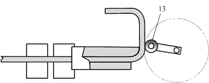
- FIG. 1 is a perspective view of a winding apparatus A according to the first embodiment.
- the wire supply means B is for sending or stopping and holding the coil wire 2 having a flat cross section, and for sending the coil wire 2 wound around a bobbin (not shown) in the direction of arrow J in the figure. It is.
- the wire supply means B is provided with two sets of drive mechanisms in which a motor and a drive roller are combined. That is, a first drive mechanism that sandwiches the coil wire 2 between the first motor 3 and the first drive roller 4 that transmits the rotation of the first motor 3 and the first drive roller 4 and the first passive roller 5 that passively rotates.
- a second drive mechanism that sandwiches the coil wire 2 by the second motor 6, the second drive roller 7, and the second passive roller 8 that passively rotates, and the drive roller and the passive roller are respectively indicated by arrows K 1.
- the coil wire 2 is sent out by rotating in the directions of arrows K2, K3, and K4.
- the coil wire 2 is first fed by the first drive roller 4 and the first passive roller 5, guided by the wire guide 9a, and further driven by the second drive roller 7 and the second passive roller 8 to reach the wire guide 9b.
- a bending guide 9ba is provided at the end of the wire guide 9b as described later. Further, the coil wire 2 is gripped by stopping the rotation of each motor.
- Each motor can be provided with a speed reducer to make the rotation speed appropriate, and has a control device (not shown) for starting and stopping the rotation of the motor.
- a control device not shown
- the motor A linear motion conversion mechanism using a screw and a screw may be used.
- the bending means C is provided with a bending pressing body 13 via a lever 12 on a rotating shaft 11 of a bending motor 10 which is a rotating mechanism, and rotates (revolves) in an arrow L direction (clockwise).
- the coil wire 2 is bent upward (counterclockwise) with the bending guide 9ba, which will be described later, in contact as a fulcrum.
- the distal end of the bending pressing body 13 is circular, and is bent while smoothly rotating on the coil wire 2 at the time of bending.
- the bending press body 13 shows the structure which bends the coil wire 2 while rotating like a roller which is free to rotate with respect to the lever 12, the bending press body 1 is fixed to the lever 12 and is coiled while sliding. The structure which bends the wire 2 may be sufficient.
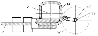
- the coil 14 is formed as shown in FIG. 2 by bending the coil wire 2 by the bending means C rotating several times.
- the lamination direction of the coil 14 is opposite to the direction in which the bending motor 10 is installed as shown in FIG.
- the center line of the coil at the position where the bending of the coil wire 2 by the bending pressing body 13 of the bending means C is completed is Z1
- the center line of the rotating shaft 11 of the bending pressing body 12 of the bending means C is Z2
- the center line Z2 is located away from the center line Z1 of the coil 14, and the coil wire 2 is positioned outside the outer peripheral surface of the coil 14 at a position after bending.
- the bending motor 10 may drive the rotary shaft 11 from a position separated by driving a belt or the like.
- FIGS. 3 to 10 are views from the XX direction shown in FIG.
- FIG. 3 shows step 1 and shows a state before the coil wire 2 starts winding, the rotating shaft 11 and the bending pressing body 13 are stopped, and the coil wire 2 is moved in the direction of arrow J. It is fed from the wire guide 9b.
- a circular two-dot chain line indicates a rotation locus of the bending pressing body 13.
- the feeding length of the coil wire 2 is controlled by the number of rotations and the rotation angle of the motor of the wire supply means B.
- the bending pressing body 13 rotating in the direction of the arrow L approaches the coil wire 2 and the bending pressing body 13 comes into contact with the coil wire 2, and the coil wire 2 Bending is started around the curved bending guide 9ba at the end of the wire guide 9b.
- FIG. 5 shows Step 3 and shows a state in which the coil wire 2 is bent at approximately 90 degrees through the curved portion 2a.
- the bending pressing body 13 is rotated clockwise and moved to the most leftmost position, and the coil wire 2 is rotated about 90 degrees counterclockwise or 90 degrees in consideration of the effect of springback in some cases. Bend deeply into the following acute angles.
- the bending pressing body 13 further rotates, bends the coil wire 2, and gradually moves away from the coil wire 2. 4 to 6, the coil wire 2 does not move and maintains its position.
- the supply of the coil wire 2 is thereafter performed by the wire supply means B. Is started.
- the bending pressing body 13 also continues to rotate, and the bending pressing body 13 moves faster, so that the linear portion 2b of the coil wire 2 contacts the bending pressing body 13 as shown in FIG. There is no.
- the timing which sends the coil wire 2 may be made after the bending press body 13 leaves
- a sensor for detecting the rotational position of the bending pressing body may be provided.
- the wire supply means B stops sending and holding the coil wire 2 as shown in step 5 of FIG.
- the bending pressing body 13 continues to rotate and approaches the coil wire 2. At this time, since the driving load applied to the bending pressing body 13 is small, the speed can be increased to save time. In particular, useless time can be eliminated when one side of the rectangular shape is short.
- FIG. 8 shows step 6 in which the bending pressing body 13 abuts on the coil wire 2 and bending is started around the end 9ba of the bending guide 9b, and the second bending is completed in step 7 of FIG. To do.
- bending is performed by decreasing the rotational speed and increasing the motor torque.
- the coil wire 2 is fed by the length of the other side of the rectangular coil, and the third bending process is performed in step 8 of FIG.
- rectangular coils 14 stacked as shown in FIG. 2 are manufactured.
- the coil wire 2 is bent by the bending pressing body 13 of the bending means C, and the center Z1 of the coil and the center Z2 of the rotating shaft 11 when the coil 14 is formed as shown in FIG. Z2 is located further outside the outer periphery of the coil 14. Further, the rotation locus W of the bending pressing body 13 does not intersect the outer periphery of the coil 14 at this position.
- the bending pressing body 13 and the coil wire 2 are not in contact except during bending, and the bending pressing body 13 needs to be rotated in the reverse direction or moved in the coil stacking direction. You can see that there is no. Further, when the bending pressing body 13 is started, the bending motor 10 can be controlled easily and can be rotated at high speed because the bending motor 10 can be continuously rotated in one direction without moving the central axis in the axial direction. is there.
- an induction motor, a synchronous motor, a stepping motor or the like generally called a servo motor is used, and if a position detector that detects the rotational position of the bending pressing body 13 is provided, higher-precision control is possible. Become.
- a rectangular laminated coil that is close to a square made up of four bent portions and a straight non-bent portion connecting between the bent portions is shown.
- the wire rod It can be applied by adjusting the feed amount of the supply means B.
- a quadrangular laminated coil composed of four bent portions and a linear portion communicating between them, but also other polygonal coils can be applied.
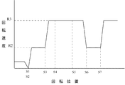
- FIG. 1 An example of the rotation speed control of the bending pressing body 13 is shown by a graph in FIG.
- the horizontal axis indicates the rotational position of the bending pressing body 13, and the vertical axis indicates the rotational speed of the bending pressing body 13.
- the bending pressing body 13 is stationary at the initial position S1 point of Step 1 in FIG. 3 and the coil wire 2 is supplied, and the bending pressing body 13 starts rotating from the S2 point (Step 2 in FIG. 4). Since the load is large due to the bending, the rotation speed is decreased (rotation speed R2) and the driving torque of the bending motor 10 is increased to perform bending.
- Point S3 is the state of step 3 in FIG.
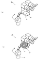
- FIG. 12 to 13 are perspective views showing the configuration of the second embodiment of the present invention.
- the difference from the first embodiment is that the direction of the entire winding device A is changed.
- the coil 14 is rotated and bent horizontally with respect to gravity, and the coil 14 is laminated in the direction of gravity.
- FIG. 13A there is a coil support 20 that supports the coil 14 that is bent, and an inclined guide 20 a is provided on a part of the coil support 20.
- FIG. 13B the coil 14 is bent and guided on the inclined guide 20 a and laminated on the coil support 20.
- the bending motor 10 is installed in a direction opposite to the direction in which the coils 14 are laminated (downward in FIG. 13), and prevents the bending motor 10 from being contacted by the lamination of the coils 14.
- FIG. 14 is a perspective view showing the configuration of the third embodiment of the present invention.
- the difference from the first embodiment is that a position changing means D in the horizontal direction is provided.
- the position changing means D comprises a moving motor 15, a linear conversion mechanism 16 and a drive shaft 17, and converts the rotational motion of the mobile motor 15 into a linear motion by a linear conversion mechanism 16 constituted by a screw mechanism. Is driven in the direction indicated by arrow N.
- the drive shaft 17 can be moved in contact with the table 18 and the bending means C fixed to the table 18 can be moved.
- the other position changing means E is moved at right angles to the moving direction of the position changing means D, and can be moved in two dimensions by two position changing means, and a moving device (not shown) that moves vertically.
- the bending angle can be adjusted by the movement of the bending means C.
- the bending angle can be adjusted by changing the position of the bending pressing body 13 in the state of step 3 in FIG.
- the table 18 is moved to the bending guide 9b side by the position changing means D, the bending amount is increased and the table 18 is bent at an acute angle.
- the position changing means D is operated to move the bending pressing body 13 and bend it at an acute angle as shown in the coil wire 2c.
- FIG. 16 shows a schematic diagram of the operation of the fourth embodiment of the present invention.
- the difference from the first embodiment is that a plurality of bending pressing bodies are provided. That is, apart from the bending pressing body 13 attached to the rotating shaft 11 via the lever 12, the bending pressing body 13a is provided symmetrically with respect to the rotating shaft 11 via the lever 12a.
- two bending pressing bodies it is possible to bend twice by one rotation of the rotating shaft 11 and to reduce the coil manufacturing time even if the rotating shaft is at a low speed.
- the case where two bending pressing bodies are used is shown, but three or more bending pressing bodies are also possible.
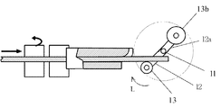
- FIG. 17 shows a schematic diagram of the operation of the fifth embodiment of the present invention.
- the difference from the fourth embodiment is that two bending pressing bodies 13 and 13b having different sizes are provided.
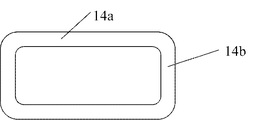
- the ratio of the long side 14a and the short side 14b is greatly different in a rectangular coil as shown in FIG. 18, the amount of springback generated during bending is different, and the coil shape may be distorted. .
- the bending pressing body 13b having a size different from that of the bending pressing body 13 can be provided to reduce the influence of the spring back, and an accurate dimension can be obtained even in a rectangular coil having different long sides and short sides.
- the coil can be manufactured.
- the position of the bending pressing body 13b in the rotational direction is 180 degrees with respect to the bending pressing body 13 in the embodiment, but can be changed to an appropriate position depending on the shape of the rectangular coil.
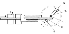
- FIG. 19 shows a schematic diagram of the operation of the sixth embodiment of the present invention.
- the difference from the fifth embodiment is that two bending pressing bodies having different rotation radii are provided.
- the bending pressing body 13 c is attached to the bending pressing body 13 attached to the lever 12 and the lever 12 b having a longer radius than the lever 12.
- the bending pressing body 13 bends the coil wire 2 and then further bends to a more acute angle by the bending pressing body 13c, so that dimensional accuracy can be maintained even when the springback is large.
- the position of the bending pressing body 13c in the rotation direction is 180 degrees with respect to the bending pressing body 13 in the embodiment, but can be changed depending on the shape of the rectangular coil.
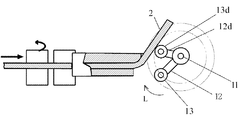
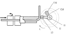
- FIG. 20 and 21 are schematic diagrams showing the operation of the seventh embodiment of the present invention.
- the bending pressing body 13d apart from the bending pressing body 13, the bending pressing body 13d is provided on a lever 12d having a small rotation radius.
- the bending pressing body 13d bends the coil wire 2 at a predetermined angle, and then the bending pressing body 13 bends the coil wire 2 by 90 degrees as shown in FIG.
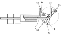
- FIG. 22 is a schematic diagram showing the operation
- FIG. 23 is a block diagram of the bending position detecting means
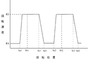
- FIG. 24 is a graph showing the rotational speed of the bending pressing body 13.
- the bending motor 10 increases the rotational speed from the position Sa where the bending pressing body 13 has finished bending the coil wire 2, and when reaching the position Sb, the coil wire 2 is sent from the position U 1 to the position U 2. It is done.
- the bending pressing body 13 further rotates and reaches the position Sc before the bending pressing body 13 bends the coil wire 2, the bending pressing body 13 is detected by the bending position detecting means 19 as shown in FIG.
- the bending motor 10 decelerates and reaches the position Sd where the bending pressing body 13 contacts the coil wire 2 in a state where the rotational speed of the bending pressing body 13 is reduced.
- the bending pressing body 13 touches softly without damaging the surface of the coil wire 2, and thereafter bends the coil wire 2 at a low speed.
- the generated torque is large, and the bending motor 10 can rotate with a sufficient margin during bending with a large load.
- the bending position detection means 19 may be a reflection type optical sensor, a metal proximity sensor, or the like in addition to the transmission type optical sensor as shown in the embodiment.
- the rotational position Sa1 indicates the state of the rotational position Sa in FIG. 22, and the rotational speed is the low speed R4. Since the coil wire 2 has already been bent at this position, the rotational speed is increased to R5.
- the bending pressing body 13 passes through the position of Sb in FIG. 22 (Sb1 in FIG. 24) at high speed, and continues to rotate at a high speed even after the coil wire 2 is sent and reaches the position of Sc as described above.
- the position is detected by the means 19, and the rotation speed is decelerated from R5 (rotation position Sc1) to R4 (rotation position Sd). Thereafter, this operation is repeated to stack the nonlinear coils.
- the positions Sa and Sb can be determined from the rotational speed of the bending motor 10 according to time, but may be detected using a position detection sensor. Further, the bending position detecting means 19 can count the number of times the coil wire 2 is bent, and can detect a predetermined number of times of bending, that is, the number of laminated coils.
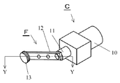
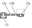
- FIG. 25 is a perspective view showing the configuration of the ninth embodiment.
- the turning radius changing means F is changed by changing the attachment position of the lever 12 attached to the rotating shaft 11 of the bending means C and changing the length of the lever 12 to act.
- Form. 26 is a cross-sectional view taken along the line YY of FIG. 25.
- the lever 12 is provided with a plurality of mounting holes 12a, 12b, and 12c, and the rotation radius can be changed depending on the mounting position on the rotary shaft 11.
- FIG. 26 and FIG. 27 show a state in which the rotation radius is attached to the hole 12a which is the longest position.
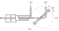
- the rotation radius By increasing the rotation radius, it is possible to perform a bending process at a high speed by providing a plurality of bending pressing bodies 13 even for a large coil shape as shown in FIG. Even if one side of the coil wire 2 is lengthened from the position U1 to the position U3, the bending pressing bodies 13e and 13f can be provided to be opposed to each other by 180 degrees, so that the number of bendings per rotation can be made twice. That is, the bending pressing body 13f can send the wire coil 2 to the position U3. At this time, the bending motor 13e has not yet reached the bending position. If the coil wire 2 can be sent from U1 to U3 between the angles ⁇ in the figure, it can be bent continuously, and the winding speed of the coil increases.
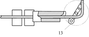
- the position of the fulcrum is set to the position of the hole 12c, and the bending pressing body 13 is rotated with a small turning radius. If the generated torque of the bending motor is the same, the force acting on the bending pressing body 13 at this time becomes large, and processing can be performed even with a coil with a small curvature radius or a coil wire with a high hardness material.
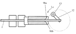
- FIG. 29 and FIG. 30 are operation schematic diagrams showing Embodiment 10 of the present invention.
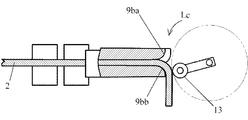
- a wire rod guide 9bb is provided oppositely, the rotation direction of the bending pressing body is rotated in the counterclockwise Lc direction opposite to the conventional one, and the coil wire 2 as shown in FIG. Is bent downward in the figure.
- the coil support 20 shown in FIG. 1 is also provided in the opposite direction to FIG. It is also possible to create a parallel type coil by initially rotating the bending pressing body 13 clockwise and then rotating it counterclockwise from the middle.
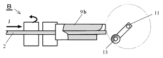
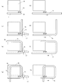
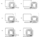
- FIGS. 31 to 36 show an eleventh embodiment of the present invention, in which a rectangular coil of 7.6 mm ⁇ 2 mm is wound edgewise, and the operation of a rectangular spiral coil having an outermost circumference of 84 mm ⁇ 84 mm and an innermost circumference of 28 mm ⁇ 28 mm is shown. It is a schematic diagram.
- a specific dimension is an example, Comprising: This invention is not limited to this dimension. The process of winding from a coil with a large circumference as a first winding process and winding a coil with a small circumference in order will be described.
- FIG. 31A shows the state of the initial position before winding the coil, and the coil wire 2 is sent out from the end 2d along the wire guide 9b by the wire supply means B (FIG. 1).
- Reference numeral 20 denotes a coil support as coil moving means.
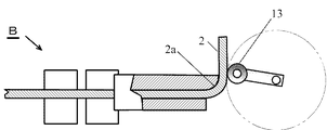
- the coil wire 2 stops when it is fed a predetermined length (straight line portion 2e), and the bending roller 13 rotates and the bent portion 2f of the coil wire 2 rotates as shown in FIG. 31 (c).
- the first bend is performed along the wire guide 9b at the portion.
- the terminal is taken out in this first bending, for example, in the case of a rectangular coil having a length of one side of the outermost periphery of 84 mm, it is set to be slightly longer, for example, about 110 mm.
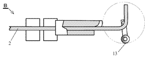
- the coil wire 2 is sent by the wire rod supply means B in the direction of the arrow, for example, 60 mm (straight line portion 2g), and stopped.
- the bending roller 13 continues to rotate during this time, and as shown in FIG. 31E, after the coil wire 2 completes feeding, the second bending is performed again at the bending portion 2h. At this time, the coil wire rod tip 2d and the straight line portion 2e run on the coil support 20 and rotate while being guided.
- the coil wire 2 Since the straight portion 2h is guided by the guide surface 20a (see FIG. 13) of the coil support 20, the coil wire 2 is deformed by moving in a direction perpendicular to the bending coil surface.
- the inclination of the coil support 20 is set so that the deformation amount is equal to or less than the elastic limit of 2.
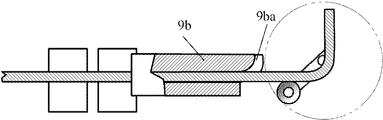
- the coil wire 2 is sent to the same length (60 mm) of the straight portion 2g as the second delivery (FIG. 31 (d)) as the third delivery.
- the bending roller 13 performs bending at the bent portion 2j.
- the wire from the straight portion 2e to the straight portion 2g is guided by the coil support 20 and rotates.
- the linear portion 2e is guided to the outside of the wire rod guide 9b (FIG. 3) by the coil support 20 and intersects the coil wire rod 2 passing through the inside of the wire rod guide 9b in three dimensions, so that they do not interfere with each other.
- the wire coil 2 is sent out shorter than the third feed amount 60mm than the width of the coil wire 2 (7.6 mm in this embodiment), for example, the length of the straight portion 2k.
- the length is set to 52 mm, and the fourth feeding is performed.
- the fourth bending is performed at the bending portion 2m. Since the straight portion 2e is guided to the outside of the wire guide 9b as described above, it intersects the supplied coil wire 2 three-dimensionally.
- the fifth delivery of the coil wire 2 is set to the same length as the fourth as shown in FIG. 32 (b), and the bent portion 2p is bent as shown in FIG. 32 (c).
- the bent portion 2g is guided to the outside of the wire guide 9b, the bent portion 2e and the bending roller 13 do not interfere with each other, and the fifth turn is performed at the bent portion 2p.
- the sixth delivery is made shorter than the fifth delivery amount of 52 mm and shorter than the width of the coil wire 2 and the length of the straight portion 2q is set to 44 mm, for example.
- a sixth turn is performed by the bent portion 2r.
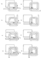
- the seventh time (FIGS. 32 (f) and 32 (g)) is 44 mm
- the eighth time (FIGS. 32 (h) and 33 (a)) and the ninth time (FIG. 33 (b) and FIG. 33 (c)) is the delivery amount 36 mm
- the 10th time (FIGS. 33 (d) and 33 (e)) and the 11th time (FIGS. 33 (f) and 33 (g)) are the delivery amount 28mm
- the 13th time (FIG. 34 (b) and FIG. 8 (c)) are the winding and bending of the coil wire 2 having a feed amount of 20 mm.
- a rectangular spiral coil is formed from the larger circumference to the smaller circumference.
- the coil wire of the practical part is described with a small width so that it does not overlap with the broken line, but since it is actually one wire with the same diameter, the width of the wire is the same as in the first step .
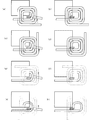
- the 16th time (FIGS. 34 (h) and 35 (a)) and the 17th time (FIGS. 35 (b) and 35 (c)) are the delivery amount 28 mm, and the 18th time (FIGS. 35 (d) and 35 (e)).
- ) And 19th time (FIGS. 35 (f) and 35 (g) show a delivery amount of 36 mm, and 20th time (FIGS. 35 (h), 36 (a) and 21st times (FIGS. 36 (b) and 36)).
- Feeding amount 44 mm, 22nd time (FIGS. 36D and 36E are sent and bent at a feeding amount of 52 mm, and the coil wire 2 is cut and as shown in FIG. 36F.
- a rectangular spiral coil that overlaps two layers (a part is one layer) is formed.
- the first winding step and the second winding step constitute one winding unit, and the connection terminal can be taken out from the outermost periphery.
- the connection terminal can be taken out from the outermost periphery.
- a coil laminated in three or more layers can be manufactured.
- the bending roller 13 is continuously rotated, the coil wire 2 is continuously supplied, and the coil wire can be cut halfway or wound from the other end. There is no so-called one-stroke writing.
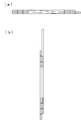
- FIG. 37 and 38 show a spiral coil produced by the manufacturing method of Example 11.
- FIG. 37 (a) is a front view
- (b) is a rear view
- (c) is a right side view
- (d) is a left side view
- (e) is a plan view
- (f) is a bottom view
- FIG. (A) and (b) of FIG. 37 are an AA sectional view and a BB sectional view, respectively, shown in the front view of FIG.
- the rectangular spiral coil shown in FIG. 37 has a maximum of four turns formed in two layers. The coil already wound when the coil wire 2 is bent is guided by the coil support 20 and deformed in a direction perpendicular to the surface around which the coil is wound.
- the size of the coil support guide 20 needs to be selected to an optimum value depending on the elastic coefficient of the coil wire, the winding length of the coil, etc. If it is the size shown in Example 11 with the copper wire rod obtained, there will be no problem in particular and manufacture is possible.
- the coil wire is continuously wound from one end by providing a portion where the wire does not overlap in the winding unit on the innermost peripheral portion and the outermost peripheral portion of the spiral coil. Is possible.
- winding is started from one end 2a of the coil wire, wound from one having a large coil circumference to one having a small coil circumference, and continuously wound from one having a small coil circumference to one having a large coil circumference. Since it rotates, the outermost periphery and innermost periphery of a coil are comprised so that the number of turns may decrease. That is, many are wound in two layers, but by providing one layer portion on the innermost and outermost circumferences, it is possible to manufacture by winding continuously from the end 2a of the coil wire in the same direction. it can. Since one side of the non-linear coil is shortened in the inner peripheral portion of the spiral, it is conceivable that the amount of coil movement exceeds the elastic limit. However, slight deformation is acceptable as long as it is within an allowable range for thin dimensions. Particularly in the innermost circumference, there is a portion where there is no overlap in one turn unit, so that the thin dimensions can be maintained.
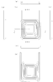
- 39 and 40 show a coil of Example 12 of the present invention.
- the difference from Example 11 is that the coil wire is round.
- 39 (a) is a front view
- (b) is a rear view
- (c) is a right side view
- (d) is a left side view
- (e) is a plan view
- (f) is a bottom view.
- (A) and (b) are a CC sectional view and a DD sectional view, respectively, shown in the front view of FIG. 39 (a).
- the coil by a round wire has the fault that a coil size will become large when an electric current density is equivalent, since it is a coil wire material generally manufactured, there exists an advantage which can manufacture a coil at low cost.
Abstract
Afin d'obtenir un dispositif qui présente une configuration simple et qui enroule rapidement une bobine non circulaire telle qu'une bobine rectangulaire, la présente invention porte sur un dispositif d'enroulement qui est équipé : d'un moyen d'alimentation en matériau de fil qui fait avancer et serre un matériau de fil de bobine; d'un guide de pliage disposé sur une partie du moyen d'alimentation en matériau de fil; et d'un moyen de pliage qui amène le matériau de fil de bobine à entrer en contact avec le guide de pliage, ce qui permet de plier le matériau de fil de bobine. Le moyen de pliage a un centre de rotation situé à une position sur l'extérieur de la bobine après que le matériau de fil de bobine a été plié, et tourne de façon répétée dans un seul sens, et l'entraînement du matériau de fil de bobine par le moyen d'alimentation en matériau de fil amène le moyen de pliage rotatif à entrer en contact avec le guide de pliage, ce qui permet de fabriquer une bobine non circulaire. Par conséquent, une bobine non circulaire peut être fabriquée rapidement par rotation répétée du moyen de pliage sans déplacer le moyen de pliage dans la direction d'empilement de la bobine.
Applications Claiming Priority (4)
| Application Number | Priority Date | Filing Date | Title |
|---|---|---|---|
| JP2014-239854 | 2014-11-27 | ||
| JP2014239854A JP5780538B1 (ja) | 2014-09-01 | 2014-11-27 | 巻線装置 |
| JP2015152483A JP6476472B2 (ja) | 2015-07-31 | 2015-07-31 | 巻線装置 |
| JP2015-152483 | 2015-07-31 |
Publications (1)
| Publication Number | Publication Date |
|---|---|
| WO2016084442A1 true WO2016084442A1 (fr) | 2016-06-02 |
Family
ID=56074023
Family Applications (1)
| Application Number | Title | Priority Date | Filing Date |
|---|---|---|---|
| PCT/JP2015/074443 WO2016084442A1 (fr) | 2014-11-27 | 2015-08-28 | Dispositif d'enroulement |
Country Status (2)
| Country | Link |
|---|---|
| JP (1) | JP6476472B2 (fr) |
| WO (1) | WO2016084442A1 (fr) |
Cited By (3)
| Publication number | Priority date | Publication date | Assignee | Title |
|---|---|---|---|---|
| CN109391107A (zh) * | 2017-08-10 | 2019-02-26 | 丰田自动车株式会社 | 绕线装置 |
| US20200358343A1 (en) * | 2017-09-29 | 2020-11-12 | Korea Institute Of Industrial Technology | Distributed straight-angle armature winding, motor comprising same, and method for manufacturing same |
| CN114783764A (zh) * | 2022-04-25 | 2022-07-22 | 山东华东风机有限公司 | 一种线圈绕线用可调距工装 |
Citations (1)
| Publication number | Priority date | Publication date | Assignee | Title |
|---|---|---|---|---|
| JP2012038871A (ja) * | 2010-08-06 | 2012-02-23 | Nittoku Eng Co Ltd | 螺旋状コイルの製造方法及びその製造装置 |
Family Cites Families (7)
| Publication number | Priority date | Publication date | Assignee | Title |
|---|---|---|---|---|
| JP3351172B2 (ja) * | 1995-05-23 | 2002-11-25 | 松下電器産業株式会社 | 薄形トランス |
| JP3007597B2 (ja) * | 1997-10-21 | 2000-02-07 | 日特エンジニアリング株式会社 | 外外巻コイルの巻線方法と巻線装置 |
| JP3438867B2 (ja) * | 1999-09-03 | 2003-08-18 | 株式会社東京マルイ | 玩具銃に用いる楕円コイルばねの製造方法 |
| JP2011050215A (ja) * | 2009-08-28 | 2011-03-10 | Toyota Motor Corp | 巻線方法及び巻線装置 |
| JP2014100008A (ja) * | 2012-11-15 | 2014-05-29 | Toyota Motor Corp | 巻線装置及び巻線方法 |
| JP3196150U (ja) * | 2014-08-11 | 2015-02-26 | 康雄 中西 | 拡縮型双方向巻き連結コイル |
| JP5780538B1 (ja) * | 2014-09-01 | 2015-09-16 | 株式会社アンド | 巻線装置 |
-
2015
- 2015-07-31 JP JP2015152483A patent/JP6476472B2/ja active Active
- 2015-08-28 WO PCT/JP2015/074443 patent/WO2016084442A1/fr active Application Filing
Patent Citations (1)
| Publication number | Priority date | Publication date | Assignee | Title |
|---|---|---|---|---|
| JP2012038871A (ja) * | 2010-08-06 | 2012-02-23 | Nittoku Eng Co Ltd | 螺旋状コイルの製造方法及びその製造装置 |
Cited By (6)
| Publication number | Priority date | Publication date | Assignee | Title |
|---|---|---|---|---|
| CN109391107A (zh) * | 2017-08-10 | 2019-02-26 | 丰田自动车株式会社 | 绕线装置 |
| CN109391107B (zh) * | 2017-08-10 | 2020-06-16 | 丰田自动车株式会社 | 绕线装置 |
| US20200358343A1 (en) * | 2017-09-29 | 2020-11-12 | Korea Institute Of Industrial Technology | Distributed straight-angle armature winding, motor comprising same, and method for manufacturing same |
| US11824407B2 (en) * | 2017-09-29 | 2023-11-21 | Korea Institute Of Industrial Technology | Distributed straight-angle armature winding, motor comprising same, and method for manufacturing same |
| CN114783764A (zh) * | 2022-04-25 | 2022-07-22 | 山东华东风机有限公司 | 一种线圈绕线用可调距工装 |
| CN114783764B (zh) * | 2022-04-25 | 2023-09-29 | 山东华东风机有限公司 | 一种线圈绕线用可调距工装 |
Also Published As
| Publication number | Publication date |
|---|---|
| JP6476472B2 (ja) | 2019-03-06 |
| JP2017034081A (ja) | 2017-02-09 |
Similar Documents
| Publication | Publication Date | Title |
|---|---|---|
| US9287042B2 (en) | Winding device and winding method for edgewise coil | |
| JP5617365B2 (ja) | エッジワイズ巻きコイル製造装置 | |
| JP4278700B1 (ja) | エッジワイズコイルの巻線方法及び巻線装置 | |
| EP2854263B1 (fr) | Procédé de bobinage de bobine et dispositif de bobinage | |
| JP5756609B2 (ja) | コイルばね製造装置 | |
| US8225491B2 (en) | Coil manufacturing method | |
| JP6140566B2 (ja) | コイル装着方法及びコイル装着治具 | |
| WO2016084442A1 (fr) | Dispositif d'enroulement | |
| US10693355B2 (en) | Coil unit arrangement device | |
| JP5703989B2 (ja) | エッジワイズコイルの巻線装置および巻線方法 | |
| JP5780538B1 (ja) | 巻線装置 | |
| JP6212756B2 (ja) | 巻取装置 | |
| CN103331394B (zh) | 双扭簧双侧同步有芯绕制机构 | |
| JP5535141B2 (ja) | 空芯コイルの巻線方法及び巻線装置 | |
| JP2012054480A (ja) | トロイダルコイルの製造装置及びその製造方法 | |
| JP2014100008A (ja) | 巻線装置及び巻線方法 | |
| JP2013021041A5 (fr) | ||
| JP6664664B2 (ja) | 巻線装置 | |
| JP6476465B2 (ja) | 巻線装置 | |
| JP2011110569A (ja) | コイル状線材の矯正装置及び矯正方法 | |
| JP6442737B2 (ja) | コイルの巻線方法および巻線装置 | |
| WO2012147297A1 (fr) | Dispositif de fabrication de bobine de profil et son procédé de fabrication | |
| KR101498777B1 (ko) | 나선형 와이어 성형장치 | |
| JP2008312345A (ja) | 巻線装置及び回転電機の製造方法 | |
| CN200976532Y (zh) | 电机外向齿铁心螺旋卷绕装置 |
Legal Events
| Date | Code | Title | Description |
|---|---|---|---|
| 121 | Ep: the epo has been informed by wipo that ep was designated in this application |
Ref document number: 15863665 Country of ref document: EP Kind code of ref document: A1 |
|
| NENP | Non-entry into the national phase |
Ref country code: DE |
|
| 122 | Ep: pct application non-entry in european phase |
Ref document number: 15863665 Country of ref document: EP Kind code of ref document: A1 |