WO2016080229A1 - 磁気探傷装置および磁気探傷方法 - Google Patents
磁気探傷装置および磁気探傷方法 Download PDFInfo
- Publication number
- WO2016080229A1 WO2016080229A1 PCT/JP2015/081486 JP2015081486W WO2016080229A1 WO 2016080229 A1 WO2016080229 A1 WO 2016080229A1 JP 2015081486 W JP2015081486 W JP 2015081486W WO 2016080229 A1 WO2016080229 A1 WO 2016080229A1
- Authority
- WO
- WIPO (PCT)
- Prior art keywords
- magnetic
- detection
- defect
- magnetic field
- inspection object
- Prior art date
Links
Images


Classifications
-
- G—PHYSICS
- G01—MEASURING; TESTING
- G01N—INVESTIGATING OR ANALYSING MATERIALS BY DETERMINING THEIR CHEMICAL OR PHYSICAL PROPERTIES
- G01N27/00—Investigating or analysing materials by the use of electric, electrochemical, or magnetic means
- G01N27/72—Investigating or analysing materials by the use of electric, electrochemical, or magnetic means by investigating magnetic variables
- G01N27/82—Investigating or analysing materials by the use of electric, electrochemical, or magnetic means by investigating magnetic variables for investigating the presence of flaws
- G01N27/83—Investigating or analysing materials by the use of electric, electrochemical, or magnetic means by investigating magnetic variables for investigating the presence of flaws by investigating stray magnetic fields
- G01N27/87—Investigating or analysing materials by the use of electric, electrochemical, or magnetic means by investigating magnetic variables for investigating the presence of flaws by investigating stray magnetic fields using probes
-
- G—PHYSICS
- G01—MEASURING; TESTING
- G01N—INVESTIGATING OR ANALYSING MATERIALS BY DETERMINING THEIR CHEMICAL OR PHYSICAL PROPERTIES
- G01N27/00—Investigating or analysing materials by the use of electric, electrochemical, or magnetic means
- G01N27/72—Investigating or analysing materials by the use of electric, electrochemical, or magnetic means by investigating magnetic variables
- G01N27/82—Investigating or analysing materials by the use of electric, electrochemical, or magnetic means by investigating magnetic variables for investigating the presence of flaws
- G01N27/90—Investigating or analysing materials by the use of electric, electrochemical, or magnetic means by investigating magnetic variables for investigating the presence of flaws using eddy currents
Definitions
- the present invention relates to a magnetic flaw detection apparatus and a magnetic flaw detection method for flaw detection of a predetermined defect (abnormality) in an inspection object by using a magnetic detection unit that detects magnetism.
- the method of inspecting the presence or absence of defects (abnormalities) such as scratches and thinning (thinning) of metal pipes such as steel pipes, iron pipes and aluminum pipes is mainly ultrasonic using ultrasonic waves in addition to visual observation.
- a leakage magnetic flux flaw detection method for detecting a magnetic flux (defect leakage magnetic flux) generated by a defect by applying a DC magnetic field (DC magnetic field) or an AC magnetic field (AC magnetic field) to an inspection object see, for example, Patent Document 1).
- Patent Document 2 An eddy current flaw detection method (see, for example, Patent Document 2) for detecting a change caused by a defect in an eddy current induced in an AC magnetic field in an object to be inspected is known.
- a magnetic flaw detector Helmholtz type magnetic flaw detector using a Helmholtz coil that generates a magnetic field (magnetic field) has also been proposed (see, for example, Patent Document 3).
- a multi-structure tube such as a heat insulating tube, in which a plurality of cylindrical bodies having different diameters formed from materials such as a magnetic body and a conductor are radially multiplexed.
- the outermost tube has a significantly larger magnetic field change than the innermost tube and it is difficult to detect the inner tube.
- the Helmholtz coil-type magnetic flaw detector disclosed in Patent Document 3 uses a double-insulated heat insulating tube as an inspection object, but even if a defect is detected by a change in magnetic field, With one magnetic sensor arranged on the outer peripheral surface, it is difficult to distinguish whether this defect occurs in the inner tube or the outer tube.
- the present invention has been made in view of the above-described circumstances, and its object is to provide a magnetism that can determine the position of a predetermined defect in the inspection object along the first direction that is in contact with the inspection object.
- a flaw detection apparatus and a magnetic flaw detection method are provided.
- the magnetic flaw detection apparatus and the magnetic flaw detection method according to the present invention can determine the position of a predetermined defect in the inspection object along the first direction that is separated from and in contact with the inspection object.
- a magnetic flaw detection apparatus and a magnetic flaw detection method apply a magnetic field to an inspection object, detect magnetism at a plurality of first detection positions different from each other from the outer surface of the inspection object, and based on these detection results Then, a position of a predetermined defect in the inspection object along a first direction that is separated from and in contact with the inspection object is obtained.
- FIG. 1 is a diagram showing a configuration of a magnetic flaw detector in the embodiment. 1A shows the overall configuration, and FIG. 1B is a cross-sectional view around the magnetic field application unit.
- FIG. 2 is a perspective view showing an appearance of an object to be inspected by the magnetic flaw detector according to the embodiment.
- FIG. 3 is a diagram for explaining a method for calculating a defect position in the magnetic flaw detector according to the embodiment.
- the magnetic flaw detection apparatus applies a magnetic field to an inspection object to be inspected, and first contacts and disconnects the change in the magnetic field caused by a predetermined defect (abnormality) of the inspection object. Detected at a plurality of first detection positions at different distances from the outer surface of the inspection object along the direction, and based on each detection result, the position of a predetermined defect in the inspection object along the first direction Is a device for obtaining
- the magnetic flaw detector M in such an embodiment includes, for example, as shown in FIG. 1, a magnetic field application unit 1a, a first group detection unit 3a, and a control processing unit 4 including a defect position processing unit 42.
- an input unit 5, an output unit 6, and an interface unit (IF unit) 7 are further provided.
- the magnetic field application unit 1a is a device that applies a magnetic field to the inspection object SP.
- the inspected object SP is preferably a metal pipe SPa such as a steel pipe, an iron pipe, and an aluminum pipe, and more preferably a plurality of cylindrical bodies having different diameters formed of a material such as a magnetic body or a conductor. It is a multi-structure tube that is multiplexed in multiple directions.
- the inspected object SP is a heat insulating pipe SPa of a double structure pipe shown in FIG. As shown in FIG.
- the heat insulating pipe SPa includes, for example, a steel pipe SPa1 positioned inside, a heat insulating material SPa2 that covers the outer periphery of the steel pipe SPa1 with a predetermined thickness, and an outer surface that covers the outer periphery of the heat insulating material SPa2.
- a hot-dip galvanized iron plate SPa3 which is an exterior sheet metal.
- the magnetic field application unit 1 a includes an excitation coil 11 a and a power supply unit 12.
- the exciting coil 11a is a device that generates a magnetic field by receiving power supply from the power supply unit 12, and applies the generated magnetic field to the inspection object SP.
- various known devices can be used according to a flaw detection method such as a leakage magnetic flux flaw detection method or an eddy current flaw detection method.
- the exciting coil 11a is configured to generate a magnetic flux in the inspection object SP by applying a DC magnetic field or an AC magnetic field.
- the exciting coil 11a is configured to generate an eddy current in the inspection object SP by applying an alternating magnetic field.
- the exciting coil 11a as the first mode includes a pair of first and second exciting coils 11a-1 and 11a-2 shown in FIG.
- the pair of first and second exciting coils 11a-1 and 11a-2 are arranged with the heat insulating pipe SPa inserted through the cores thereof and spaced apart at a predetermined interval along the axial direction of the heat insulating pipe SPa.
- the predetermined interval is appropriately set, and is, for example, a length substantially equal to the radius of the first and second exciting coils 11a-1 and 11a-2 in order to constitute a Helmholtz coil.
- the first exciting coil 11a-1 is a wire rod having a long electrical conductivity such as a round cross section or a square cross section, for example, on the first coil bobbin 111a-1 which is a tubular body having a relatively short height (short height).
- the first conductor member 112a-1 is formed by winding it through an insulating material such as resin or oil paper.
- the second exciting coil 11a-2 is a second wire bobbin 111a-2, which is a short and high cylindrical body, which is a second wire having a long electrical conductivity such as a round cross section or a square cross section.
- the conductor member 112a-2 is formed by winding it through an insulating material such as resin or oil paper.
- the first and second coil bobbins 111a-1 and 111a-2 are made of, for example, a nonmagnetic insulator such as a resin material.
- the number of turns of the first and second exciting coils 11a-1 and 11a-2 is appropriately determined according to the strength of the desired magnetic field to be generated by the first and second exciting coils 11a-1 and 11a-2. Is set.
- Each of the first and second conductor members 112a-1 and 112a-2 is a conductor wire having a relatively high conductivity, such as copper or aluminum, and insulated and coated with a resin.
- the first and second exciting coils 11a-1 and 11a-2 are connected in series with each other. More specifically, one end of the first excitation coil 11a-1 is connected to the power supply unit 12, the other end is connected to one end of the second excitation coil 11a-2, and the other end is connected to the power source. Connected to the unit 12.
- the power supply unit 12 is a device that is connected to the control processing unit 4 and generates magnetism (magnetic field) by supplying electric power to the exciting coil 11a according to the control of the control processing unit 4.
- the power supply unit 12 supplies a predetermined current corresponding to the flaw detection method such as a direct current, an alternating current and a pulse current to the pair of first and second exciting coils 11a-1 and 11a-2, thereby supplying a direct current magnetic field,
- a predetermined magnetic field corresponding to the flaw detection method such as an alternating magnetic field and a pulsed magnetic field (pulse magnetic field) is generated.
- the power supply unit 2 supplies the first and second excitation coils 11a-1 and 11a-2 to the pair of first and second excitation coils 11a-11a-2 in order to supply a current of opposite phase or only to one of them.
- a switching circuit for appropriately switching each energizing path to 11a-2 may be provided.
- the first group detection unit 3a includes a plurality of first magnetic detection units 31a that detect magnetism.
- the plurality of first magnetic detectors 31a are between the pair of exciting coils 11a-1 and 11a-2 and include on the outer surface (directly above and above) of the object SP to be inspected. Is arranged at a plurality of first detection positions at different distances from the outer surface along a first direction that is separated from or in contact with the object SP.
- Each of the plurality of first magnetic detection units 31 a is connected to the control processing unit 4, detects magnetism corresponding to the flaw detection method, and outputs the detection result to the control processing unit 4. For example, in the leakage magnetic flux flaw detection method, magnetism due to leakage magnetic flux generated by a defect is detected.
- the first group detection unit 3a includes three first magnetic detection units 31a-1 to 31a-3. These three first magnetic detectors 31a-1 to 31a-3 are located between the pair of exciting coils 11a-1 and 11a-2 and on the outer peripheral surface of the heat insulation pipe SPa in the radial direction of the heat insulation pipe SPa. Are arranged at three first detection positions at first to third distances different from each other from the outer peripheral surface.
- the first magnetic detection unit 31a includes a magnetic sensor using a magnetoresistive element (MR element) that utilizes a magnetoresistive effect in which the electrical resistance changes according to a magnetic field, and a skin effect of a high permeability alloy magnetic material.
- MR element magnetoresistive element
- Magnetic sensor using magneto-impedance element using magneto-impedance effect that changes impedance by magnetic field, magnetic sensor using hall element using hall effect, flux gate using magnetic saturation of high permeability material The magnetic sensor used, and a magnetic sensor element using a superconducting quantum interference device (SQUID, Superducting Quantum Interference Device) using a superconductor ring having a Josephson junction at two locations are used.
- SQUID superconducting quantum interference device
- the input unit 5 is connected to the control processing unit 4.
- various commands such as a command for instructing the measurement of the inspection object SP, and an identifier (for example, an identification number of the inspection object) in the inspection object SP, for example.
- a device that inputs various data necessary for measuring input or the like to the magnetic flaw detector M such as a plurality of input switches assigned with predetermined functions, a keyboard, a mouse, and the like.
- the output unit 6 is connected to the control processing unit 4, and under the control of the control processing unit 4, commands and data input from the input unit 5, and measurement results of the inspection object SP measured by the magnetic flaw detector M (for example, a device that outputs the measurement data of the magnetic detection unit 3, the presence / absence of a defect, and the position of the defect), for example, a display device such as a CRT display, LCD (liquid crystal display) and organic EL display, a printing device such as a printer It is.
- a display device such as a CRT display, LCD (liquid crystal display) and organic EL display
- a printing device such as a printer It is.
- a touch panel may be configured from the input unit 5 and the output unit 6.
- the input unit 5 is a position input device that detects and inputs an operation position such as a resistive film method or a capacitance method
- the output unit 6 is a display device.
- a position input device is provided on the display surface of the display device, one or more input content candidates that can be input to the display device are displayed, and the user touches the display position where the input content to be input is displayed. Then, the position is detected by the position input device, and the display content displayed at the detected position is input to the magnetic flaw detector M as the operation input content of the user.
- the magnetic flaw detector M that is easy for the user to handle is provided.
- the IF unit 7 is a circuit that is connected to the control processing unit 4 and inputs / outputs data to / from an external device according to the control of the control processing unit 4.
- an interface circuit of an RS-232C that is a serial communication system
- the control processing unit 4 is a circuit for controlling each part of the magnetic flaw detector M according to the function of each part.
- the control processing unit 4 includes, for example, a microcomputer having a CPU (Central Processing Unit), a memory, and peripheral circuits thereof.
- a control unit 41 and a defect position processing unit 42 are functionally configured by executing a program.
- the control unit 41 is for controlling each part of the magnetic flaw detector M according to the function of each part.
- the defect position processing unit 42 obtains the position of a predetermined defect in the inspection object SP along the first direction based on each detection result of the plurality of first magnetic detection units 31a in the first group detection unit 3a. Is. In the above-described example, the defect position processing unit 42 follows the radial direction of the heat insulating pipe SPa based on the detection results of the three first magnetic detection units 31a-1 to 31a-3 in the first group detection unit 3a. In addition, the position of a predetermined defect in the heat insulating pipe SPa is obtained.
- the defect position processing unit 42 uses the following condition 1 and condition 2 to thereby inspect the inspection object SP based on the detection results of the plurality of first magnetic detection units 31a in the first group detection unit 3a.
- the magnetic field strengths at a plurality of observed positions within the outer surface and at different distances from the outer surface along the first direction are obtained, and based on the obtained magnetic field strengths at the plurality of observed positions, The position of a predetermined defect in the object SP is obtained.
- Condition 1 The detection result of the first magnetic detection unit 31a is that each magnetic field at a plurality of observed positions propagates from the plurality of observed positions to the first detection position of the first magnetic detection unit 31a.
- Condition 2 is the sum of magnetic field strengths; the magnetic field strength has a specific relationship with the distance between the observed position and the first detection position
- the defect position processing unit 42 obtains the position of the defect as follows.
- the magnetic field strength at the observed position is MI0
- the horizontal axis X is a distance along the radial direction from the outer peripheral surface of the steel pipe SPa1 with the outer peripheral surface of the steel pipe SPa1 as the coordinate origin
- the vertical axis Y is
- the magnetic field intensity MI at the steel pipe SPa1 is MI01
- the magnetic field intensity MI at the molten zinc iron plate SPa3 of the outer sheet metal is MI02
- the distance from the outer peripheral surface of the steel pipe SPa1 to the outer peripheral surface of the molten zinc iron plate SPa3 is X0.
- each detection result ⁇ (X) is obtained as a measurement value by measurement of the first magnetic detection units 31a-1 to 31a-3. Therefore, the magnetic field strength MI01 in the steel pipe SPa1 and the magnetic field strength MI02 in the molten zinc iron plate SPa3 are obtained by using two of the above three formulas.
- a curve ⁇ (X) that best matches (fits) each detection result of the first magnetic detectors 31a-1 to 31a-3 is obtained by, for example, the least square method, and the obtained curve ⁇ (X) is obtained.
- the magnetic field intensity MIref1 in the steel pipe SPa1 obtained in advance is compared with the magnetic field intensity MI01 in the obtained steel pipe SPa1, and the presence or absence of the defect is determined.
- the difference between the magnetic field intensity MIref1 and the magnetic field intensity MI01 in the steel pipe SPa1 is within the predetermined first range th1 in consideration of noise, it is determined that there is no defect, and the magnetic field in the steel pipe SPa1 is determined.
- the difference between the intensity MIref1 and the magnetic field intensity MI01 exceeds the predetermined first range th1, it is determined that there is a defect, and the inner steel pipe SPa1 located relatively radially inside has a defect. It is determined that there is.
- the magnetic field strength MIref2 obtained in the molten zinc iron plate SPa3 and the magnetic field strength MI02 obtained in the molten zinc iron plate SPa3 are compared, and the presence or absence of the defect is determined.
- the difference between the magnetic field strength MIref2 and the magnetic field strength MI02 in the molten zinc iron plate SPa3 is within the predetermined second range th2 in consideration of noise, it is determined that there is no defect, and the molten zinc iron plate If the difference between the magnetic field strength MIref2 and the magnetic field strength MI02 at SPa3 exceeds the predetermined second range th2, it is determined that there is a defect, and the outer tube located relatively radially outside is melted. It is determined that the zinc iron plate SPa3 has a defect. That is, the position of the defect along the radial direction can be determined. Alternatively, as will be described later, in the case where a plurality of second group detection units 3b (see FIG.
- the presence / absence of a defect is determined by each magnetic field in the steel pipe SPa1 obtained at each position in the circumferential direction. It may be carried out by comparing the strength MI01 with each other. If they are different, it is determined that the steel pipe SPa1 is defective at that position, and the molten zinc iron plate SPa3 obtained at each position in the circumferential direction. It may be carried out by comparing the magnetic field strengths MI02 of each other. If they are different, it is determined that there is a defect in the molten zinc iron plate SPa3 at that position. As will be described later, when a plurality of third group detectors 3c (see FIG.
- the presence / absence of a defect is determined by each magnetic field in the steel pipe SPa1 obtained at each position in the axial direction. It may be carried out by comparing the strength MI01 with each other, and if they are different, it is determined that the steel pipe SPa1 is defective at that position, and the molten zinc iron plate SPa3 obtained at each position in the axial direction It may be carried out by comparing the magnetic field strengths MI02 of each other. If they are different, it is determined that there is a defect in the molten zinc iron plate SPa3 at that position.
- the measured data ⁇ described above may use a difference from the state without the defect instead of the measurement value itself.
- the magnetic field strength MI01 and the magnetic field strength MIre1 and the magnetic field strength MI02 and the magnetic field strength MIref2 can be compared as they are.
- the magnetic flaw detector M can determine the presence or absence of a defect by comparing the magnetic field strengths at the obtained plurality of observed positions with the magnetic field strengths in a normal state without defects. As a result, the position of the defect Can be requested.
- the inspection object SP is a multiple structure tube in which a plurality of cylindrical bodies having different diameters are multiplexed in the radial direction
- the defect position processing unit 42 includes a plurality of first tubes in the first group detection unit 3a.
- Two first magnetic detectors 31a among the magnetic detectors 31a are selected, and the first of the two selected first magnetic detectors 31a is far from the outer surface along the first direction. From the detection result of the magnetic detection unit 31a, the detection result of the first magnetic detection unit 31a having a short distance from the outer surface along the first direction of the two selected first magnetic detection units 31a is set to the far first.
- the defect position processing unit 42 obtains the position of the defect as follows.
- the first magnetic detection unit 31a-1 is located at a first detection position at a distance of 1 mm from the outer peripheral surface of the molten zinc iron plate SPa3, and the first magnetic detection unit 31a-2 is at a distance of 5 mm from the outer peripheral surface of the molten zinc iron plate SPa3.
- the defect position processing unit 42 has a long distance X from the outer peripheral surface along the radial direction of the two first magnetic detection units 31a-1 and 31a-2.
- the detection result ⁇ (1 mm) of the first magnetic detector 31a-1 is If the difference from the detection result ⁇ (5 mm) of the first magnetic detector 31a-2 is relatively large, the inner pipe steel pipe SPa1 is defective, and the outer pipe steel pipe SPa3 is not defective, the first magnetic detector 31a
- the determination threshold th3 is applied by the magnetic field application unit 1a because the difference between the detection result ⁇ (1 mm) of ⁇ 1 and the detection result ⁇ (5 mm) of the first magnetic detection unit 31a-2 is relatively small.
- the defect position processing unit 42 determines that the steel pipe SPa1 of the inner pipe is defective when the subtraction result ⁇ sub is greater than or equal to the determination threshold th3, and when the subtraction result ⁇ sub is less than the determination threshold th3, It determines with the steel pipe SPa1 of an inner pipe having no defect, and calculates
- a curve ⁇ (X) that best fits (fits) each detection result of the first magnetic detectors 31a-1 to 31a-3 is obtained by, for example, the least square method, and the obtained curve ⁇ ( X), the detection result ⁇ (1 mm) of the first magnetic detection unit 31a-1 and the detection result ⁇ (5 mm) of the first magnetic detection unit 31a-2 are obtained.
- each first magnetic detection unit The distance X from the outer peripheral surface of the molten zinc iron plate SPa in 31a-1 to 31a-3 may be measured by a distance meter or the like.
- Such a magnetic flaw detector CM uses the fact that the magnetic field strength attenuates in inverse proportion to the square of the distance, thereby checking the presence or absence of defects in the inner cylindrical body from the outermost cylindrical body.
- the position of the predetermined defect in the object SP can be easily obtained.
- the magnetic flaw detector CM is suitable when the inspection object SP is a double structure pipe.
- a test object SP such as a heat insulating tube SPa
- a pair of first and second exciting coils 11a-1 and 11a of the test object SP is performed by a user (operator). -2 are arranged at a predetermined interval.
- the control processing unit 4 executes initialization of each necessary unit, and the control processing unit 4 includes the control unit 41 and the defect position processing by executing the program.
- the unit 42 is functionally configured.
- the control unit 41 When receiving an instruction to start flaw detection by the user via the input unit 5, the control unit 41 causes the power supply unit 2 to apply a current corresponding to the flaw detection method to the pair of first and second exciting coils 11a-1 and 11a-2. Supply power.
- the pair of first and second exciting coils 11a-1 and 11a-2 generates a magnetic field (magnetic field) according to the flaw detection method, and applies the magnetic field to the inspection object SP.
- This magnetic field is transmitted through the inspection object SP, and the magnetic field caused by this magnetic field is detected by the plurality of first magnetic detection units 31a of the first group detection unit 3a, and the plurality of first magnetic detection units 31a Is output to the control processing unit 4.
- the defect position process part 42 determines the presence or absence of the predetermined defect in the to-be-inspected object SP based on each detection result of the some 1st magnetic detection part 31a, and determines the position of the defect along a 1st direction. .
- the control unit 41 outputs each detection result of the plurality of first magnetic detection units 31a, the presence / absence of a defect, and the position of the defect along the first direction to the output unit 6. Note that the control unit 41 detects the detection results of the plurality of first magnetic detection units 31a, the presence / absence of a defect, and the position of the defect along the first direction as necessary via an IF unit 7 as an external device (not shown). May be output.
- the magnetic flaw detection apparatus M and the magnetic flaw detection method mounted thereon have a plurality of first detection positions at a plurality of first detection positions different from each other from the outer surface of the inspection object SP. Since the magnetism can be detected by the first magnetic detection unit 31a, the defect position processing unit 42 follows the first direction (in the above example, the radial direction) that is separated from or in contact with the inspection object SP based on each detection result. The position of a predetermined defect in the inspection object SP can be obtained. In the above-described example, it is required whether the steel pipe SPa1 located on the inner side in the radial direction has a defect or whether the molten zinc iron plate SPa3 located on the outer side in the radial direction has a defect.
- FIG. 4 is a diagram illustrating a configuration of a first modification of the magnetic flaw detector according to the embodiment.
- FIG. 5 is a diagram illustrating a configuration of a second modification of the magnetic flaw detector according to the embodiment.
- the magnetic flaw detector M includes a plurality of second flaws at different distances from the outer surface along the first direction on the outer surface of the inspection object SP.
- the second group detection unit 3b is arranged at a predetermined angular interval with respect to the first group detection unit 3a along a circumferential direction around an axis with a second direction orthogonal to the first direction as an axis. Yes.
- the defect position processing unit 42 is based on the detection results of the plurality of first magnetic detection units 31a in the first group detection unit 3a and the plurality of second magnetic detection units 31b in the second group detection unit 3b.
- the position of the predetermined defect in the inspection object SP along the first direction and the position of the predetermined defect in the inspection object SP along the circumferential direction is obtained.
- the number of the second group detection unit 3b may be one.
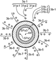
- in order to detect a predetermined defect over the entire circumference of the heat insulation pipe SPa in the example shown in FIG. 3b includes 11 second group detection units 3b-1 to 3b-11.
- Each of these eleventh second group detectors 3b-1 to 3b-11 has three second detection positions at different distances from the outer surface of the heat insulation pipe SPa along the radial direction on the outer surface of the heat insulation pipe SPa.
- the second group detection unit 3b-1 is arranged at an angular interval of about 30 degrees along the circumferential direction around the central axis AX of the heat insulation pipe SP orthogonal to the radial direction with respect to the first group detection unit 3a.
- the eleventh second group detectors 3b-1 to 3b-11 are sequentially arranged around the central axis AX of the heat insulation pipe SPa at an angular interval of about 30 degrees along the circumferential direction. . That is, the first group detection unit 3a and the eleventh second group detection units 3b-1 to 3b-11 sequentially form an angular interval of about 30 degrees around the central axis AX of the heat insulation pipe SPa along the circumferential direction. They are spaced apart (ie, equally spaced).
- the magnetic flaw detector CM according to the first modified embodiment includes the second group detection unit 3b arranged along the circumferential direction with respect to the first group detection unit 3a. Can be sought. In particular, the magnetic flaw detector CM in the example shown in FIG. 4 can determine the position of the defect over the entire circumference of the heat insulating tube SPa.
- the magnetic flaw detector M has a plurality of first flaws at different distances from the outer surface along the first direction on the outer surface of the inspection object SP.
- the third group detection unit 3c is arranged with a predetermined interval with respect to the first group detection unit 3a along a second direction orthogonal to the first direction.
- the defect position processing unit 42 is based on the detection results of the plurality of first magnetic detection units 31a in the first group detection unit 3a and the plurality of third magnetic detection units 31c in the third group detection unit 3c.
- the position of the predetermined defect in the inspection object SP along the first direction and the position of the predetermined defect in the inspection object SP along the second direction is obtained.
- the number of the third group detection unit 3c may be one, in order to detect a predetermined defect over a predetermined range along the axial direction in the heat insulating pipe SP, in the example shown in FIG. 3c includes four third group detectors 3c-1 to 3b-4.
- Each of the four third group detection units 3c-1 to 3b-4 has three third detection positions on the outer surface of the heat insulation pipe SPa at three different distances from the outer surface of the heat insulation pipe SPa along the radial direction.
- the third group detector 3c-1 is arranged at a predetermined interval along the axial direction of the central axis AX of the heat insulating pipe SPa perpendicular to the radial direction with respect to the first group detector 3a.
- the third group detectors 3c-1 to 3b-4 are sequentially arranged at a predetermined interval along the axial direction of the central axis AX of the heat insulating pipe SPa. That is, the first group detection unit 3a and the four third group detection units 3c-1 to 3c-4 are sequentially spaced at a predetermined interval along the axial direction of the central axis AX of the heat insulation pipe SPa (that is, (Equally spaced).
- the magnetic flaw detector CM according to the second modified example includes the third group detection unit 3c arranged along the second direction (in the example shown in FIG. 5, the axial direction) with respect to the first group detection unit 3a. Therefore, the position of the defect can be obtained over the second direction.
- the magnetic flaw detector CM of the example shown in FIG. 5 can determine the position of the defect over a predetermined range along the axial direction of the heat insulating tube SPa.
- the magnetic flaw detector CM may be configured to include a group detection unit in which the group detection unit 3B of the second mode and the group detection unit 3C of the third mode are combined instead of the group detection unit 3a of the first mode.
- Such a magnetic flaw detector M can determine the position of the defect both in the radial direction and in the axial direction.
- the magnetic field application unit 1 of the first mode including the pair of exciting coils 11a-1 and 11a-2 is used.
- the magnetic field application unit 1b or the magnetic field application unit 1c of the third aspect may be used.
- FIG. 6 is a diagram illustrating a configuration of a third modification of the magnetic flaw detector according to the embodiment. 6A shows the overall configuration, and FIG. 6B is a cross-sectional view around the exciting coil.
- FIG. 7 is a diagram illustrating a configuration of a fourth modification of the magnetic flaw detector according to the embodiment. FIG. 7A shows a front view around the exciting coil, and FIG. 7B is a sectional view around the exciting coil.
- the magnetic field application unit 1b of the second aspect is a device that applies a magnetic field to the object to be inspected SP. As shown in FIG. With. Since the power supply unit 12 in the magnetic field application unit 1b of the second aspect is the same as the power supply unit 12 in the magnetic field application unit 1a of the first aspect, description thereof is omitted.
- the excitation coil 11b is a device that generates a magnetic field by receiving power supply from the power supply unit 12 and applies the generated magnetic field to the inspection object SP, similarly to the excitation coil 11a of the first mode.
- the exciting coil 11b includes a pair of first and second exciting coils 11b-1 and 11b-2 shown in FIG.
- the first and second exciting coils 11b-1 and 11b-2 include magnetic shielding portions 111b-1 and 111b-2 and conductor members 112b-1 and 112b-2, respectively. Since the first and second exciting coils 11b-1 and 11b-2 have the same shape, they will be collectively described below as the magnetic shield 111b, the conductor member 112b, and the exciting coil 11b.
- the magnetic shielding part 111b is a member for shielding magnetism, and is formed in a curved plate shape.
- the magnetic shielding part 111b is preferably curved according to the shape of the heat insulating pipe SPa. More specifically, the magnetic shielding part 111b is, for example, a part of a cylinder (hollow column) cut along the axial direction, and its cross section orthogonal to the axial direction is arcuate (partial shape of the ring). It has become.
- the arc-shaped cross section of the magnetic shielding part 111b is similar to a part of the cross section of the heat insulating pipe SPa so as to follow the outer peripheral surface of the heat insulating pipe SPa.
- the central angle of the magnetic shielding part 111b is 180 degrees or less in order to be able to be disposed on the outer peripheral surface of the heat insulating pipe SPa (including directly above (abuttingly disposed on the outer peripheral surface) and above (including spaced from the outer peripheral surface)). Preferably there is.
- the center angle of the magnetic shielding part 111b can also slightly exceed 180 degree
- the central angle of the magnetic shield 111b may be any one of 120 degrees, 90 degrees, and 60 degrees.
- the magnetic shielding part 111b having such a central angle can be executed by a plurality of exciting coils 11b having the same shape when surrounding the entire circumference of the heat insulating pipe SP as will be described later, including the case of 180 degrees. Therefore, the excitation coil 11b having the same shape may be mass-produced, so that the cost of the excitation coil 11b can be reduced due to the mass production effect.
- Such a magnetic shielding part 111b is formed of, for example, an electromagnetic steel plate, preferably a plurality of laminated electromagnetic steel plates.
- the magnetic shielding part 111b is formed by compressing soft magnetic powder having an insulating film.
- the conductor member 112b is a wire having a long electrical conductivity such as a round cross section and a square cross section, and is wound along the outer peripheral surface of the magnetic shielding portion 111b via an insulating material such as resin or oil paper, A coil is formed.
- the conductor member 112b is a conductor wire having a relatively high conductivity such as copper or aluminum and insulated and coated with a resin.
- Such a first excitation coil 11b-1 is formed by winding a long first conductor member 112b-1 around a curved plate-like first magnetic shield 111b-1, so that the first conductor member 112b- A part of 1 has an overlapping portion that overlaps with the first magnetic shield 111b-1 in the radial direction.
- the second exciting coil 11b-2 is formed by winding the long second conductor member 112b-2 around the second magnetic shielding part 111b-2 having a curved plate shape, so that the second conductor member 112b- 1 has a superposed portion that overlaps in the radial direction via the second magnetic shielding portion 111b-2.
- first conductor member 112b-1 in the first excitation coil 11b-1 is connected to the power supply unit 12, and the other end of the first conductor member 112b-1 is the second end in the second excitation coil 11b-2.
- the conductor member 112b-2 is connected to one end, and the other end of the second conductor member 112b-2 is connected to the power supply unit 12.
- the first and second exciting coils 11b-1 and 11b-2 are connected in series.
- the first and second excitation coils 11b-1 and 11b-2 can be supplied with currents in opposite directions (currents of opposite phases), and the first and second excitation coils 11b-1 and 11b can be supplied.
- the one end and the other end of the second conductor member 112b-2 in the second excitation coil 11b-2 may be connected to the power supply unit 12, respectively.
- the magnetic flaw detector CM provided with the magnetic field application unit 1b of the second aspect as described above has long conductor members 112b-1 and 112b that are bent plate-like magnetic shielding units 111b-1 and 111b-2 with an insulating material interposed therebetween.
- -2 is provided with a pair of exciting coils 11b-1 and 11b-2. Therefore, each cross-sectional shape in each of the pair of exciting coils 11b-1 and 11b-2 is an arc shape. Therefore, for inspection, for example, a pair of exciting coils 11b-1, 11b- are provided along the concave curved surfaces of the exciting coils 11b-1, 11b-2 on the outer surface of the inspection object SP such as a tube. 2 can be arranged.
- the magnetic field application unit 1a of the first aspect has the pair of exciting coils 11a-1 from the end of the piping to the inspection location. 11a-2 must be moved, which is cumbersome and time consuming. Further, when inspecting a pipe that is actually disposed, the pair of exciting coils 11a-1 and 11a-2 may not be able to move to the inspection location due to a fixture or support of the pipe. For this reason, in the magnetic field application unit 1a of the first aspect, even if an electrical connector is provided on the conductor members 112a-1 and 112a-2 in order to open the respective excitation coils 11a-1 and 11a-2. Although it is good, it is also conceivable that a problem occurs in the electrical connector. However, since the magnetic field application unit 1b of the second aspect can be arranged in a pipe such as the heat insulation pipe SPa as described above, the above situation can be avoided.
- the magnetic field application unit 1b is configured to include one pair of excitation coils 1, but is not limited thereto, and may be configured to include a plurality of pairs of excitation coils 11b. . Since such a magnetic flaw detector M includes a plurality of pairs of excitation coils 11b, a plurality of pairs of excitation coils 11b can be arranged along the length direction of the object SP to be inspected. A wider range of the inspection object SP can be detected in the direction. Further, the magnetic flaw detector M can arrange a plurality of pairs of exciting coils 11b along the circumferential direction of the inspection object SP, and thereby detect a wider range of the inspection object SP in the circumferential direction.
- the magnetic flaw detector M When the magnetic flaw detector M includes a plurality of pairs of excitation coils 11b, the plurality of pairs of excitation coils 11b are preferably arranged in a cylindrical shape. Since the magnetic flaw detector M includes a plurality of pairs of excitation coils 11b that are sequentially arranged adjacent to each other in the circumferential direction so as to have a cylindrical shape, the magnetic flaw detector M includes the plurality of pairs of excitation coils 11b.
- a substantially Helmholtz coil can be constituted by a pair of excitation coils 11b, and a more uniform magnetic field can be formed across the entire circumferential direction between the pair of excitation coils 11b like a Helmholtz coil.
- the magnetic field application unit 11c of the third aspect includes two pairs of excitation coils 11b arranged in a cylindrical shape and a power supply unit 12 (not shown). Since the power supply unit 12 (not shown) in the magnetic field application unit 1c of the third aspect is the same as the power supply unit 12 in the magnetic field application unit 1a of the first aspect, the description thereof is omitted. More specifically, as shown in FIG. 7, the magnetic field application unit 11c of the third mode includes a pair of first and second excitation coils 11b-1, 11b-2 and a pair of third and fourth excitations. Two pairs of exciting coils 11b including coils 11b-3 and 11b-4 are provided. In the example shown in FIG.
- the pair of first and second exciting coils 11b-1 and 11b-2 are connected in series and connected to a power supply unit 12 (not shown).
- the pair of third and fourth exciting coils 11b-3 and 11b-4 are connected in series and connected to a power supply unit 12 (not shown).
- the adjacent part of each conductor member 112b in the exciting coils 11b adjacent to each other in the circumferential direction is preferably arranged so as to be parallel to each other along the radial direction.
- adjacent portions P1 and P2 of the conductor members 112b-1 and 112b-3 in the first exciting coil 11b-1 and the third exciting coil 11b-3 that are adjacent to each other in the circumferential direction are in the radial direction.
- unillustrated adjacent portions P3 and P4 of the respective conductor members 112b-2 and 112b-4 in the second exciting coil 11b-2 and the fourth exciting coil 11b-4 that are adjacent to each other in the circumferential direction are along the radial direction.
- the end surfaces parallel to the axial direction in the first and third magnetic shielding portions 111b-1 and 111b-3 having a semi-cylindrical shape with a central angle of 180 degrees are formed flat along the radial direction. Is done.
- the adjacent portions P1 and P2 The first and third conductor members 112b-1 and 112b-3 are substantially parallel to each other.
- the end surfaces parallel to the axial direction of the second and fourth magnetic shielding members 111b-2 and 111b-4 having a semi-cylindrical shape with a central angle of 180 degrees are formed flat so as to be along the radial direction.
- the adjacent portions P3 and P4 The second and fourth conductor members 112b-2 and 112b-4 are substantially parallel to each other.
- the respective conductor members 112b-1, 112b-3; 112b-2, 112b in the exciting coils 11b-1, 11b-3; 11b-2, 11b-4 adjacent to each other in the circumferential direction are provided.
- the magnetic flaw detector M can form a more uniform magnetic field by using the two pairs of exciting coils 11b-1, 11b-2; 11b-3, 11b-4.
- a magnetic flaw detection apparatus includes a magnetic field applying unit that applies a magnetic field to an inspection object, and a first direction that is separated from and in contact with the inspection object on the outer surface of the inspection object.
- Each of the first group detection unit provided with a plurality of first magnetic detection units arranged at a plurality of first detection positions at different distances to detect magnetism, and each of the plurality of first magnetic detection units in the first group detection unit
- a defect position processing unit for obtaining a position of a predetermined defect in the inspection object along the first direction based on the detection result.
- Such a magnetic flaw detector can detect magnetism by a plurality of first magnetic detection units in the first group detection unit at a plurality of first detection positions different from each other from the outer surface of the inspection object. Based on each detection result, the position of the predetermined defect in the inspection object along the first direction that is separated from or in contact with the inspection object can be obtained.
- the defect position processing unit uses the following condition 1 and condition 2 to detect each detection result of the plurality of first magnetic detection units in the first group detection unit.
- the magnetic field strengths at a plurality of observed positions within the outer surface of the object to be inspected and at different distances from the outer surface along the first direction are determined, and the determined plurality of observed positions
- the position of a predetermined defect in the inspected object is obtained based on the magnetic field intensity at.
- Condition 1 The detection result of the first magnetic detection unit is that each magnetic field at the plurality of observed positions has propagated from the plurality of observed positions to the first detection position of the first magnetic detection unit.
- Condition 2 that is the sum of the magnetic field strengths of the above: the magnetic field strength has a specific relationship with the distance between the observed position and the first detection position
- Such a magnetic flaw detector uses a plurality of relational expressions relating to magnetic field strengths (magnetic field strengths) at a plurality of observed positions by using the condition 1 and the condition 2 for the detection results of the plurality of first magnetic detection units. Can be generated, and by analyzing this, the magnetic field strengths at the plurality of observed positions can be obtained. Therefore, the magnetic flaw detector can determine the presence / absence of a defect by comparing the magnetic field intensity at the obtained plurality of observed positions with the magnetic field intensity in a normal state without a defect. Can be sought.
- the inspection object is a multiple structure tube in which a plurality of cylindrical bodies having different diameters are multiplexed in the radial direction
- the defect position processing unit is Two first magnetic detection units of the plurality of first magnetic detection units in the first group detection unit are selected, and the first direction of the selected two first magnetic detection units along the first direction is selected. From the detection result of the first magnetic detection unit that is far from the outer surface, the first magnetic detection unit that has a short distance from the outer surface along the first direction out of the two selected first magnetic detection units.
- the plurality of cylindrical bodies Defects in other cylindrical bodies except the one located outside Whether there is obtained as a position of a predetermined defect in the inspection object.
- Such a magnetic flaw detector utilizes the fact that the magnetic field strength attenuates in inverse proportion to the square of the distance, thereby determining whether or not there is a defect in the inner cylindrical body from the outermost cylindrical body.
- the position of the predetermined defect in the object can be easily obtained.
- it is sufficient to determine whether the defect is in the outer tube located relatively outside or the defect in the inner tube located relatively inside. It is suitable when the inspection object is a double structure tube.
- the magnetic flaw detectors are arranged on the outer surface of the inspection object along the first direction at a plurality of second detection positions at different distances from the outer surface.
- a second group detection unit including a plurality of second magnetic detection units to be detected, wherein the second group detection unit has a second direction orthogonal to the first direction as an axis relative to the first group detection unit;
- the defect position processing unit is arranged with a predetermined angular interval along a circumferential direction around the axis to be rotated, and the defect position processing unit includes the plurality of first magnetic detection units and the second group detection unit in the first group detection unit. Based on the detection results of the plurality of second magnetic detection units, the position of the predetermined defect in the inspection object along the first direction and the predetermined defect in the inspection object along the circumferential direction Find the position.
- Such a magnetic flaw detector includes a second group detection unit arranged along the circumferential direction with respect to the first group detection unit, the position of the defect can be obtained over the circumferential direction.
- the magnetic flaw detectors are arranged at a plurality of third detection positions at different distances from the outer surface along the first direction on the outer surface of the inspection object.
- a third group detection unit including a plurality of third magnetic detection units to be detected is further provided, and the third group detection unit is located along a second direction orthogonal to the first direction with respect to the first group detection unit.
- the defect position processing unit is arranged at a predetermined interval, and the defect position processing unit detects each of the plurality of first magnetic detection units in the first group detection unit and the plurality of third magnetic detection units in the third group detection unit. Based on the result, the position of the predetermined defect in the inspection object along the first direction and the position of the predetermined defect in the inspection object along the second direction is obtained.
- Such a magnetic flaw detector includes a third group detection unit arranged along the second direction with respect to the first group detection unit, so that the position of the defect can be obtained in the second direction.
- a magnetic flaw detection method includes a magnetic field applying step of applying a magnetic field to an inspection object, and a first direction that is separated from and in contact with the inspection object on an outer surface of the inspection object.
- a magnetic detection step for detecting magnetism at each of a plurality of detection positions, and a position of a predetermined defect in the inspection object along the first direction based on each detection result detected in the magnetic detection step.
- a defect position calculation step to be obtained.
- magnetism can be detected by a magnetic detection process at a plurality of detection positions different from each other from the outer surface of the inspection object. Therefore, the inspection object is detected based on each detection result by the defect position processing process. It is possible to determine the position of a predetermined defect in the inspection object along the first direction that is separated from and in contact with the object.
- a magnetic flaw detection apparatus and a magnetic flaw detection method can be provided.
Landscapes
- Chemical & Material Sciences (AREA)
- Chemical Kinetics & Catalysis (AREA)
- Electrochemistry (AREA)
- Physics & Mathematics (AREA)
- Health & Medical Sciences (AREA)
- Life Sciences & Earth Sciences (AREA)
- Analytical Chemistry (AREA)
- Biochemistry (AREA)
- General Health & Medical Sciences (AREA)
- General Physics & Mathematics (AREA)
- Immunology (AREA)
- Pathology (AREA)
- Investigating Or Analyzing Materials By The Use Of Magnetic Means (AREA)
Priority Applications (3)
| Application Number | Priority Date | Filing Date | Title |
|---|---|---|---|
| US15/519,680 US20170241953A1 (en) | 2014-11-21 | 2015-11-09 | Magnetic flaw detection device and magnetic flaw detection method |
| EP15861676.3A EP3223010A4 (de) | 2014-11-21 | 2015-11-09 | Magnetfehlerdetektionsvorrichtung und magnetfehlerdetektionsverfahren |
| JP2016560151A JPWO2016080229A1 (ja) | 2014-11-21 | 2015-11-09 | 磁気探傷装置および磁気探傷方法 |
Applications Claiming Priority (2)
| Application Number | Priority Date | Filing Date | Title |
|---|---|---|---|
| JP2014-236335 | 2014-11-21 | ||
| JP2014236335 | 2014-11-21 |
Publications (1)
| Publication Number | Publication Date |
|---|---|
| WO2016080229A1 true WO2016080229A1 (ja) | 2016-05-26 |
Family
ID=56013774
Family Applications (1)
| Application Number | Title | Priority Date | Filing Date |
|---|---|---|---|
| PCT/JP2015/081486 WO2016080229A1 (ja) | 2014-11-21 | 2015-11-09 | 磁気探傷装置および磁気探傷方法 |
Country Status (4)
| Country | Link |
|---|---|
| US (1) | US20170241953A1 (de) |
| EP (1) | EP3223010A4 (de) |
| JP (1) | JPWO2016080229A1 (de) |
| WO (1) | WO2016080229A1 (de) |
Cited By (1)
| Publication number | Priority date | Publication date | Assignee | Title |
|---|---|---|---|---|
| JP2018146338A (ja) * | 2017-03-03 | 2018-09-20 | 新日鐵住金株式会社 | 磁気特性測定器、磁気特性測定システム、および磁気特性測定方法 |
Families Citing this family (10)
| Publication number | Priority date | Publication date | Assignee | Title |
|---|---|---|---|---|
| WO2015051225A1 (en) | 2013-10-03 | 2015-04-09 | Schlumberger Canada Limited | Pipe damage assessment system and method |
| WO2015187923A1 (en) | 2014-06-04 | 2015-12-10 | Schlumberger Canada Limited | Pipe defect assessment system and method |
| WO2017100387A1 (en) * | 2015-12-09 | 2017-06-15 | Schlumberger Technology Corporation | Fatigue life assessment |
| US11237132B2 (en) | 2016-03-18 | 2022-02-01 | Schlumberger Technology Corporation | Tracking and estimating tubing fatigue in cycles to failure considering non-destructive evaluation of tubing defects |
| KR102140170B1 (ko) * | 2018-11-27 | 2020-07-31 | 조선대학교산학협력단 | 교차 경사형 유도전류를 이용한 비파괴 검사장치용 프로브 및 비파괴 검사장치용 유도코일 제조방법 |
| US11493480B2 (en) * | 2020-10-12 | 2022-11-08 | Russell Nde Systems Inc. | Method and apparatus for the detection of corrosion under insulation (CUI), corrosion under fireproofing (CUF), and far side corrosion on carbon steel piping and plates |
| CA3135238A1 (en) * | 2020-12-08 | 2022-06-08 | Russell Nde Systems Inc. | Apparatus and method of detecting defects in boiler tubes |
| FR3119891B1 (fr) * | 2021-02-12 | 2023-11-17 | Commissariat Energie Atomique | Dispositif de caractérisation d’un bain de corium formé ou en cours de formation dans un réacteur nucléaire |
| FR3119890A1 (fr) * | 2021-02-12 | 2022-08-19 | Commissariat A L'energie Atomique Et Aux Energies Alternatives | Dispositif de caractérisation d’un bain de corium formé ou en cours de formation dans un réacteur nucléaire |
| CN113176330A (zh) * | 2021-04-30 | 2021-07-27 | 重庆能源职业学院 | 钢丝绳漏磁检测系统及该系统在电梯上的应用 |
Citations (5)
| Publication number | Priority date | Publication date | Assignee | Title |
|---|---|---|---|---|
| JP2008506931A (ja) * | 2004-07-16 | 2008-03-06 | ファウ・ウント・エム・ドイチュラント・ゲゼルシャフト・ミット・ベシュレンクテル・ハフツング | 管を非破壊検査するための方法及び装置 |
| JP2008151744A (ja) * | 2006-12-20 | 2008-07-03 | Toshiba Corp | 鋼板欠陥検査装置 |
| JP2011013087A (ja) * | 2009-07-01 | 2011-01-20 | Okayama Univ | 漏洩磁束探傷方法及び装置 |
| US20130124109A1 (en) * | 2011-10-25 | 2013-05-16 | Jentek Sensors, Inc. | Method and Apparatus for Inspection of Corrosion and Other Defects Through Insulation |
| JP2014044087A (ja) * | 2012-08-24 | 2014-03-13 | Okayama Univ | パルス磁気を用いた非破壊検査装置及び非破壊検査方法 |
Family Cites Families (6)
| Publication number | Priority date | Publication date | Assignee | Title |
|---|---|---|---|---|
| US3609531A (en) * | 1967-10-25 | 1971-09-28 | Forster F M O | Combined leakage field and eddy current flaw detector |
| JP2526578B2 (ja) * | 1986-06-26 | 1996-08-21 | 日本鋼管株式会社 | 塗膜損傷検知方法 |
| JP2005518534A (ja) * | 2002-02-26 | 2005-06-23 | シエル・インターナシヨネイル・リサーチ・マーチヤツピイ・ベー・ウイ | 物体の表面プロファイルの測定 |
| JP4234761B2 (ja) * | 2006-11-21 | 2009-03-04 | 慶一 野々垣 | 渦電流探傷方法とその装置 |
| JP4526046B1 (ja) * | 2010-01-21 | 2010-08-18 | 株式会社Ihi検査計測 | ガイド波を用いた検査方法 |
| EP2522994A1 (de) * | 2011-05-13 | 2012-11-14 | General Electric Company | Magnetische Inspektionssysteme zur Inspektion von Zielobjekten |
-
2015
- 2015-11-09 WO PCT/JP2015/081486 patent/WO2016080229A1/ja active Application Filing
- 2015-11-09 EP EP15861676.3A patent/EP3223010A4/de not_active Withdrawn
- 2015-11-09 US US15/519,680 patent/US20170241953A1/en not_active Abandoned
- 2015-11-09 JP JP2016560151A patent/JPWO2016080229A1/ja active Pending
Patent Citations (5)
| Publication number | Priority date | Publication date | Assignee | Title |
|---|---|---|---|---|
| JP2008506931A (ja) * | 2004-07-16 | 2008-03-06 | ファウ・ウント・エム・ドイチュラント・ゲゼルシャフト・ミット・ベシュレンクテル・ハフツング | 管を非破壊検査するための方法及び装置 |
| JP2008151744A (ja) * | 2006-12-20 | 2008-07-03 | Toshiba Corp | 鋼板欠陥検査装置 |
| JP2011013087A (ja) * | 2009-07-01 | 2011-01-20 | Okayama Univ | 漏洩磁束探傷方法及び装置 |
| US20130124109A1 (en) * | 2011-10-25 | 2013-05-16 | Jentek Sensors, Inc. | Method and Apparatus for Inspection of Corrosion and Other Defects Through Insulation |
| JP2014044087A (ja) * | 2012-08-24 | 2014-03-13 | Okayama Univ | パルス磁気を用いた非破壊検査装置及び非破壊検査方法 |
Non-Patent Citations (1)
| Title |
|---|
| See also references of EP3223010A4 * |
Cited By (1)
| Publication number | Priority date | Publication date | Assignee | Title |
|---|---|---|---|---|
| JP2018146338A (ja) * | 2017-03-03 | 2018-09-20 | 新日鐵住金株式会社 | 磁気特性測定器、磁気特性測定システム、および磁気特性測定方法 |
Also Published As
| Publication number | Publication date |
|---|---|
| EP3223010A1 (de) | 2017-09-27 |
| JPWO2016080229A1 (ja) | 2017-08-31 |
| US20170241953A1 (en) | 2017-08-24 |
| EP3223010A4 (de) | 2018-05-09 |
Similar Documents
| Publication | Publication Date | Title |
|---|---|---|
| WO2016080229A1 (ja) | 磁気探傷装置および磁気探傷方法 | |
| JP5522699B2 (ja) | パルス磁気を用いた非破壊検査装置及び非破壊検査方法 | |
| JP4756409B1 (ja) | 交番磁場を利用した非破壊検査装置および非破壊検査方法 | |
| WO2013024858A1 (ja) | 磁気探傷方法及び磁気探傷装置 | |
| Mao et al. | Analytical solutions to eddy current field excited by a probe coil near a conductive pipe | |
| Chen et al. | Time-domain analytical solutions to pulsed eddy current field excited by a probe coil outside a conducting ferromagnetic pipe | |
| JP4766472B1 (ja) | 非破壊検査装置及び非破壊検査方法 | |
| WO2015194635A1 (ja) | 非破壊検査装置 | |
| Tytko | Measurement of multilayered conductive discs using eddy current method | |
| Vasić et al. | Analytical modelling in low-frequency electromagnetic measurements of steel casing properties | |
| JP2016090393A (ja) | 磁気探傷装置および磁気探傷装置用励磁コイル | |
| JP6334267B2 (ja) | 渦電流探傷装置及び方法 | |
| JP2017009549A (ja) | 非破壊検査装置 | |
| JP2015194420A (ja) | 探傷方法、探傷システム、及びそれに用いる探傷プローブ | |
| JP6378554B2 (ja) | 非破壊検査装置および非破壊検査方法 | |
| JP2015230249A (ja) | 電流センサ検査システム、電流センサ検査方法 | |
| JP6175091B2 (ja) | 渦電流検査装置及び渦電流検査方法 | |
| JP2016114533A (ja) | 磁気センサー付配管及び非破壊検査装置 | |
| JP6288640B2 (ja) | 渦電流探傷プローブ、渦電流探傷装置および渦電流探傷方法 | |
| JP2013185951A (ja) | 電磁気探傷用プローブ | |
| JP2004028897A (ja) | 渦流探傷装置 | |
| JP2015017938A (ja) | 鋼材の破断部検知方法及び鋼材の破断部検知システム | |
| US20220113283A1 (en) | Method and apparatus for the detection of corrosion under insulation (cui), corrosion under fireproofing (cuf), and far side corrosion on carbon steel piping and plates | |
| JP2014066688A (ja) | 渦流探傷プローブ、渦流探傷装置 | |
| JP2016133459A (ja) | 渦流探傷プローブ、渦流探傷装置 |
Legal Events
| Date | Code | Title | Description |
|---|---|---|---|
| 121 | Ep: the epo has been informed by wipo that ep was designated in this application |
Ref document number: 15861676 Country of ref document: EP Kind code of ref document: A1 |
|
| ENP | Entry into the national phase |
Ref document number: 2016560151 Country of ref document: JP Kind code of ref document: A |
|
| WWE | Wipo information: entry into national phase |
Ref document number: 15519680 Country of ref document: US |
|
| NENP | Non-entry into the national phase |
Ref country code: DE |
|
| REEP | Request for entry into the european phase |
Ref document number: 2015861676 Country of ref document: EP |