WO2016080176A1 - ガスセンサ素子 - Google Patents
ガスセンサ素子 Download PDFInfo
- Publication number
- WO2016080176A1 WO2016080176A1 PCT/JP2015/080868 JP2015080868W WO2016080176A1 WO 2016080176 A1 WO2016080176 A1 WO 2016080176A1 JP 2015080868 W JP2015080868 W JP 2015080868W WO 2016080176 A1 WO2016080176 A1 WO 2016080176A1
- Authority
- WO
- WIPO (PCT)
- Prior art keywords
- gas
- measured
- sensor element
- main body
- layer
- Prior art date
- Legal status (The legal status is an assumption and is not a legal conclusion. Google has not performed a legal analysis and makes no representation as to the accuracy of the status listed.)
- Ceased
Links
Images




Classifications
-
- G—PHYSICS
- G01—MEASURING; TESTING
- G01N—INVESTIGATING OR ANALYSING MATERIALS BY DETERMINING THEIR CHEMICAL OR PHYSICAL PROPERTIES
- G01N27/00—Investigating or analysing materials by the use of electric, electrochemical, or magnetic means
- G01N27/26—Investigating or analysing materials by the use of electric, electrochemical, or magnetic means by investigating electrochemical variables; by using electrolysis or electrophoresis
- G01N27/403—Cells and electrode assemblies
- G01N27/406—Cells and probes with solid electrolytes
- G01N27/407—Cells and probes with solid electrolytes for investigating or analysing gases
- G01N27/409—Oxygen concentration cells
-
- G—PHYSICS
- G01—MEASURING; TESTING
- G01N—INVESTIGATING OR ANALYSING MATERIALS BY DETERMINING THEIR CHEMICAL OR PHYSICAL PROPERTIES
- G01N27/00—Investigating or analysing materials by the use of electric, electrochemical, or magnetic means
- G01N27/26—Investigating or analysing materials by the use of electric, electrochemical, or magnetic means by investigating electrochemical variables; by using electrolysis or electrophoresis
- G01N27/403—Cells and electrode assemblies
- G01N27/406—Cells and probes with solid electrolytes
- G01N27/407—Cells and probes with solid electrolytes for investigating or analysing gases
- G01N27/41—Oxygen pumping cells
Definitions
- the present invention relates to a gas sensor element that detects the concentration of a specific component in a gas to be measured (that is, a gas to be measured).
- An exhaust system of an internal combustion engine for a vehicle is provided with a gas sensor that detects the concentration (for example, oxygen concentration) of a specific component in exhaust gas that is a gas to be measured.
- a gas sensor includes, for example, an oxygen ion conductive solid electrolyte body, a gas side electrode to be measured and a reference gas side electrode provided on one side and the other side of the solid electrolyte body, A gas sensor element having a porous diffusion resistance layer that covers the gas side electrode and allows the gas to be measured to pass therethrough is incorporated.
- the gas sensor element is used in a state of being heated to a high temperature (for example, 500 ° C. or higher) at which the solid electrolyte body becomes active. Therefore, if condensed water contained in the exhaust gas enters the gas sensor element and adheres to the high-temperature solid electrolyte body, a large thermal shock may be applied to the solid electrolyte body, which may cause water cracking.
- Patent Document 1 discloses a gas sensor element having a structure that improves water resistance. Specifically, the outer peripheral surface of the gas sensor element is covered with a protective layer formed of a dense porous material that can transmit exhaust gas. By setting the surface roughness Ra of the protective layer to 3.0 ⁇ m or less, the protective layer has hydrophilicity at room temperature and water repellency at high temperature. Thereby, adhesion of water droplets to the gas sensor element at a high temperature is prevented, and water cracking is suppressed.
- the gas sensor element disclosed in Patent Document 1 has the following problems.
- the fuel contains a lot of poisonous substances such as Mn, Fe, and Ca. If these poisonous substances are discharged together with the exhaust gas and adhere to the protective layer, the surface roughness Ra of the protective layer cannot be maintained at 3.0 ⁇ m or less, and the protective layer may not exhibit water repellency at high temperatures. . As a result, the water resistance performance of the gas sensor element is reduced, and moisture may enter the gas sensor element.
- the present disclosure has been made in view of such a background, and an object of the present disclosure is to provide a gas sensor element that is excellent in water resistance and poisoning resistance and can suppress damage during rapid temperature rise.
- the gas sensor element includes: A main body having an oxygen ion conductive solid electrolyte body, a measured gas side electrode provided on one surface of the solid electrolyte body, and a reference gas side electrode provided on the other surface of the solid electrolyte body; , A trap layer made of a porous material that covers the outer peripheral surface of the main body and captures a poisonous substance contained in the gas to be measured, and transmits the gas to be measured; A protective layer covering the outer peripheral surface of the trap layer and having a property of not allowing moisture to pass through; With The protective layer is formed with at least one measured gas inlet for introducing the measured gas into the measured gas side electrode through the trap layer.
- the gas sensor element includes the trap layer that covers the outer peripheral surface of the main body, and the protective layer that covers the outer peripheral surface of the trap layer. Therefore, the water resistance and poisoning resistance of the gas sensor element can be improved, and damage during rapid temperature rise can be suppressed.
- the protective layer is formed of a material having a property of not allowing moisture to permeate, for example, a dense ceramic layer having a very small porosity, so that it exhibits waterproofness regardless of its surface properties. Can do. Therefore, even if poisonous substances contained in the exhaust gas adhere to the protective layer, the waterproof property of the protective layer is maintained without deteriorating. Thereby, the penetration
- the gas to be measured inlet is formed in the protective layer. Therefore, the path connecting the inside and the outside of the gas sensor element can be limited to the measured gas inlet. Thereby, invasion of foreign substances such as poisonous substances and moisture into the gas sensor element can be effectively suppressed. Further, when the water that has entered the gas sensor element is vaporized and expanded to become water vapor, the water vapor can be quickly discharged from the gas to be measured inlet. That is, the measured gas introduction port can efficiently perform both the introduction of the measured gas from the outside and the discharge of the water vapor inside. Thereby, the pressure rise in the inside of the gas sensor element can be suppressed, and damage to the gas sensor element can be prevented.
- the trap layer is formed between the protective layer and the main body. Therefore, foreign substances such as poisonous substances and moisture in the measurement gas that come into contact with the trap layer via the measurement gas inlet can be separated from the measurement gas by the trap layer. Further, the moisture that comes into contact with the trap layer through the measured gas inlet is held in the pores of the trap layer made of a porous material. Thus, by capturing foreign substances such as poisonous substances and moisture by the trap layer, these foreign substances can be prevented from reaching the solid electrolyte body. Thereby, poisoning and water cracking of the solid electrolyte body can be suppressed.
- the main body further includes a porous diffusion resistance layer that allows the measurement gas guided to the measurement gas side electrode to pass therethrough, and the measurement gas is interposed in the main body via the porous diffusion resistance layer.
- a gas introduction path for introducing the measurement gas into the side electrode is formed, the gas introduction path has a main body side introduction port opened on the outer peripheral surface of the main body, and the protective layer.
- the at least one measured gas inlet is preferably formed at a position facing the main body inlet from the outside. In this case, the at least one measured gas inlet can be formed in the vicinity of the main body side inlet. Thereby, the flow path of the measured gas between the at least one measured gas inlet and the main body inlet can be shortened, and the sensitivity of the gas sensor element can be improved.
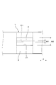
- FIG. 3 is an explanatory diagram showing a gas sensor element according to the first embodiment.
- the gas sensor element 1 includes a main body 10, a trap layer 2 that covers the outer peripheral surface 152 of the main body 10, and a protective layer 3 that covers the outer peripheral surface of the trap layer 2.
- the main body 10 includes an oxygen ion conductive solid electrolyte body 11, a measured gas side electrode 12 provided on one surface of the solid electrolyte body 11, and a reference gas side provided on the other surface of the solid electrolyte body 11.
- the electrode 13 and the porous diffusion resistance layer 14 that allows the measurement gas G guided to the measurement gas side electrode 12 to pass therethrough are provided.
- the trap layer 2 is made of a porous material that allows the gas to be measured G to pass through, and traps poisonous substances contained in the gas to be measured G.
- the protective layer 3 has a property that does not allow moisture to permeate (waterproof).
- the protective layer 3 is covered with the protective layer 3 through the trap layer 2 and the porous diffusion resistance layer 14.
- a pair of measured gas inlets 31 for introducing the measured gas G to the measured gas side electrode 12 is formed.
- the gas sensor element 1 is used for a gas sensor 100.
- the gas sensor 100 is, for example, an air-fuel mixture supplied to the internal combustion engine based on a limiting current flowing between the electrodes 12 and 13 depending on the oxygen concentration in the exhaust gas (that is, the gas G to be measured) from the internal combustion engine of the vehicle. It is configured as an A / F ratio sensor that detects an air-fuel ratio (A / F ratio).
- the gas sensor 100 includes a gas sensor element 1, an insulator 101 that inserts and holds the gas sensor element 1 inside, a housing 102 that inserts and holds the insulator 101 inside, and an atmosphere-side cover disposed on the base end side of the housing 102. 103 and an element cover 104 disposed on the front end side of the housing 102 and protecting the gas sensor element 1.
- the element cover 104 is constituted by a double-structured cover including an outer cover 105 and an inner cover 106. Conductive holes 107 for conducting the gas G to be measured are provided in the side walls and bottom walls of the outer cover 105 and the inner cover 106.
- the solid electrolyte body 11 of the gas sensor element 1 is formed by forming zirconia into a plate shape.
- the measured gas side electrode 12 and the reference gas side electrode 13 contain platinum.
- a reference gas chamber forming layer 18 made of alumina that is electrically insulating and dense and does not transmit gas is laminated.
- a groove-shaped reference gas chamber 181 into which a reference gas (for example, the atmosphere) A is introduced is formed.
- a heater substrate 19 made of alumina is laminated on the surface of the reference gas chamber forming layer 18 opposite to the surface on which the solid electrolyte body 11 is disposed.
- a heating element 191 that generates heat when energized is embedded between the reference gas chamber forming layer 18 and the heater substrate 19. And by making the heat generating body 191 generate heat by energization, the gas sensor element 1 can be rapidly heated to the activation temperature.
- a porous diffusion resistance layer 14 is laminated on both sides of the measured gas side electrode 12.
- the porous diffusion resistance layer 14 is made of a gas permeable alumina porous body.
- a shielding layer 17 made of alumina that is electrically insulating and dense and does not transmit gas is laminated on the surface of the porous diffusion resistance layer 14 opposite to the surface on which the solid electrolyte body 11 is disposed. Yes. That is, the porous diffusion resistance layer 14 is disposed between the solid electrolyte body 11 and the shielding layer 17.
- the surface of the solid electrolyte body 11 on which the measured gas side electrode 12 is provided communicates with the measured gas chamber 16 serving as a space in which the measured gas side electrode 12 is disposed, and the measured gas chamber 16.
- a gas introduction path 15 for leading the measurement gas G to the gas chamber 16 is formed.
- the porous diffusion resistance layer 14 is disposed in the gas introduction path 15.
- the gas chamber 16 to be measured is formed by being surrounded by the shielding layer 17, the porous diffusion resistance layer 14, and the solid electrolyte body 11.
- a catalyst layer 153 for removing hydrogen contained in the measurement gas G is provided at the main body side inlet 151 of the gas introduction path 15.
- the catalyst layer 153 is made of a platinum-based catalyst.
- the trap layer 2 covering the outer peripheral surface 152 of the main body 10 is a porous layer made of ceramic particles whose main component is ⁇ -alumina or ⁇ -alumina.
- the trap layer 2 is configured to trap poisonous components in the measurement gas G, for example, compounds generated from components such as P, Si, Ca, and Zn contained in the oil. .
- the trap layer 2 has a two-layer structure of a first trap layer 21 and a second trap layer 22 having different particle sizes and porosity.
- the trap layer 2 may have a single-layer structure or may have a structure of three or more layers.
- the first trap layer 21 is made of ceramic particles having a particle size of about 20 ⁇ m to 40 ⁇ m, has a porosity of about 40% to 80%, and is formed so as to cover the entire outer peripheral surface of the second trap layer 22. .
- the cross-sectional shape of the first trap layer 21 is a substantially rectangular ring shape.
- the second trap layer 22 is made of ceramic particles having a particle size of about 2 ⁇ m to 8 ⁇ m, has a porosity of about 20% to 70%, and is formed so as to cover the entire outer peripheral surface 152 of the main body 10.
- the second trap layer 22 is formed so as to partially increase in thickness at the four corners of the main body 10.
- the first trap layer 21 foreign substances such as poisonous substances are separated from the gas G to be measured, which is relatively large or viscous.
- the second trap layer 22 small foreign matters that have passed through the first trap layer 21 are separated from the gas G to be measured. Thereby, clogging in the trap layer 2 can be prevented, and the measurement gas G can be efficiently introduced into the measurement gas chamber 16.
- a protective layer 3 is formed on the outer side of the trap layer 2 so as to cover the trap layer 2.
- the protective layer 3 is a dense layer made of ceramic particles containing ⁇ -alumina as a main component and having a porosity of 5% or less.
- a pair of measured gas inlets 31 are formed in the protective layer 3.
- the measured gas introduction port 31 is formed at a position facing the main body side introduction port 151 of the gas introduction path 15 from the outside.
- the measured gas inlet 31 of the protective layer 3 is formed with a width W2 of 0.5 mm.
- the measured gas inlet 31 is formed long along the longitudinal direction Z of the gas sensor element 1, and the width W ⁇ b> 2 indicates a width in a direction orthogonal to the longitudinal direction Z.
- the measured gas inlet 31 can be formed with a width W2 of 0.5 mm to 2.0 mm.
- the measured gas introduction port 31 has a width W2 of less than 0.5 mm, the ventilation resistance of the measured gas G introduced into the measured gas chamber 16 is increased, which may hinder the flow of the measured gas G. is there.
- the width W2 of the gas inlet 31 to be measured exceeds 2.0 mm, it is not sufficient to exhibit the water resistance of the gas sensor element 1.
- the main body side inlet 151 of the gas introduction path 15 is formed with a width W1 of 0.07 mm.
- the main body side introduction port 151 is formed long along the longitudinal direction Z of the gas sensor element 1, and the width W ⁇ b> 1 indicates a width in a direction orthogonal to the longitudinal direction Z.
- the main body side inlet 151 is formed within the range of the width W2 where the measured gas inlet 31 is formed.
- the gas sensor element 1 includes a trap layer 2 that covers the outer peripheral surface 152 of the main body 10 and a protective layer 3 that covers the outer peripheral surface of the trap layer 2. Therefore, the water resistance and poisoning resistance in the gas sensor element 1 can be improved, and damage during rapid temperature rise can be suppressed.
- the protective layer 3 since the protective layer 3 is formed of a material that does not allow moisture to permeate, it can exhibit waterproofness regardless of its surface properties. Therefore, even if poisonous substances contained in the exhaust gas adhere to the protective layer 3, the waterproof property of the protective layer 3 is maintained without deteriorating. Thereby, the penetration
- a gas to be measured inlet 31 is formed in the protective layer 3. Therefore, the path connecting the inside and the outside of the gas sensor element 1 can be limited to the measured gas inlet 31. Thereby, invasion of foreign substances such as poisonous substances and moisture into the gas sensor element 1 can be effectively suppressed.
- the water that has entered the gas sensor element 1 is vaporized and expanded to become water vapor, the water vapor can be quickly discharged from the measured gas inlet 31. That is, the measured gas introduction port 31 can efficiently perform both the introduction of the measured gas G from the outside and the discharge of the internal water vapor. Thereby, the pressure rise in the inside of the gas sensor element 1 can be suppressed, and damage to the gas sensor element 1 can be prevented.
- a trap layer 2 is formed between the protective layer 3 and the main body 10. Therefore, foreign substances such as poisonous substances and moisture in the measurement gas G that come into contact with the trap layer 2 through the measurement gas inlet 31 can be separated from the measurement gas G by the trap layer 2. Further, moisture that comes into contact with the trap layer 2 through the measurement gas inlet 31 is held in the pores of the trap layer 2 made of a porous material. Thus, by capturing foreign substances such as poisonous substances and moisture by the trap layer 2, these foreign substances can be prevented from reaching the solid electrolyte body 11. Thereby, poisoning of the solid electrolyte body 11 and water cracking can be suppressed.
- the main body 10 is provided with a gas introduction path 15 for introducing the measurement gas G to the measurement gas side electrode 12 through the porous diffusion resistance layer 14.
- a gas introduction path 15 for introducing the measurement gas G to the measurement gas side electrode 12 through the porous diffusion resistance layer 14.
- the flow path of the measurement gas G between the measurement gas introduction port 31 and the main body side introduction port 151 can be shortened, and the sensitivity of the gas sensor element 1 can be improved.
- the gas inlet 31 to be measured is formed within a width W2 of 0.5 mm to 2.0 mm. Therefore, it is possible to easily introduce and discharge the gas to be measured G and water vapor while effectively suppressing the intrusion of moisture into the gas sensor element 1. Thereby, while being able to improve the moisture resistance of the gas sensor element 1 more, the pressure rise in the gas sensor element 1 can be suppressed effectively.
- the gas sensor element 1 that is excellent in water resistance and poisoning resistance and can suppress damage during rapid temperature rise.
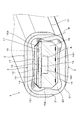
- the formation positions of the pair of measured gas inlets 31 of the protective layer 3 in the gas sensor element 1 of the first embodiment are changed.
- the pair of measured gas inlets 31 of the protective layer 3 are formed at positions away from the main body side inlet 151 of the gas introduction path 15.
- the measurement gas introduction port 31 is formed at a position facing the corner portion of the main body 10 where the main body side introduction port 151 is not formed.
- the other configurations and the contents indicated by the reference numerals in the drawing are the same as those in the first embodiment.
- the distance from the measured gas inlet 31 to the main body side inlet 151 is longer than that in the first embodiment. Then, the gas G to be measured passes through the trap layer 2 over a longer distance from the gas inlet 31 to be measured to the main body inlet 151. Therefore, it is possible to more effectively suppress moisture and poisonous substances from entering the measured gas chamber 16.
- the measured gas inlet 31 can be formed at various positions in the main body 10 according to the design conditions of the gas sensor element 1. Also according to this embodiment, the same effect as that of the first embodiment can be obtained.
- each measured gas inlet 31 of the protective layer 3 is formed by a large number of through holes having a diameter of 0.01 mm to 1.5 mm.
- the formation position of each measured gas inlet 31 of the protective layer 3 is a position facing the main body side inlet 151 as in the case of the first embodiment.
- the formation position of the measurement gas introduction port 31 by a large number of through holes may be various positions that do not face the main body side introduction port 151.
- the other configurations and the contents indicated by the reference numerals in the drawing are the same as those in the first embodiment. Also according to this embodiment, the same effect as that of the first embodiment can be obtained.
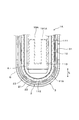
- the present embodiment exemplifies a gas sensor element 1 ⁇ / b> A using a cup-shaped solid electrolyte body 11 ⁇ / b> A instead of using the plate-shaped solid electrolyte body 11.
- the cup-shaped solid electrolyte body 11 ⁇ / b> A is formed by closing the end of a cylindrical portion 111 with a hemispherical portion 112.
- the measured gas side electrode 12 is provided on the outer periphery of the cylindrical portion 111 of the solid electrolyte body 11A
- the reference gas side electrode 13 is provided on the inner periphery of the cylindrical portion 111 of the solid electrolyte body 11A. Yes.
- an internal protective layer 23 made of a buffer material or the like is provided for covering and protecting the measured gas side electrode 12.
- a trap layer 2 including a first trap layer 21 and a second trap layer 22 is provided outside the internal protective layer 23.
- a protective layer 3 is provided outside the trap layer 2, and a measured gas inlet 31 is formed at a position facing the measured gas side electrode 12 in the protective layer 3.
- the measured gas side electrode 12 can be provided on the entire circumference of the outer periphery of the solid electrolyte body 11A, and the measured gas introduction ports 31 can be provided at a plurality of locations in the circumferential direction facing the outer circumference of the solid electrolyte body 11A.
- the measured gas inlet 31 can be formed in various shapes, for example, as shown in FIG. 6, can be formed in a shape that is long in the axial direction L of the solid electrolyte body 11A, or in FIG. As shown, it can also be formed by a large number of through holes having a size of ⁇ 0.01 mm to ⁇ 1.5 mm. In the case where the gas inlet 31 to be measured is formed by a large number of through holes, the large number of through holes can be formed in a distributed manner in the entire circumferential range facing the outer periphery of the solid electrolyte body 11A.
- the measured gas inlet 31 is formed at a position facing the measured gas side electrode 12 from the outside.
- the measured gas inlet 31 may be formed at a position that does not face the measured gas side electrode 12 from the outside.
- the heater member 19A made of alumina provided with the heating element 191A that generates heat when energized is disposed inside the solid electrolyte body 11A.
- the same effects as those of the gas sensor element 1 according to the first embodiment can be obtained by providing the protective layer 3 and the measured gas inlet 31.
- the other configurations and the contents indicated by the reference numerals in the drawings are the same as those in the first embodiment.
Landscapes
- Chemical & Material Sciences (AREA)
- Life Sciences & Earth Sciences (AREA)
- Health & Medical Sciences (AREA)
- Physics & Mathematics (AREA)
- Chemical Kinetics & Catalysis (AREA)
- Electrochemistry (AREA)
- Molecular Biology (AREA)
- Analytical Chemistry (AREA)
- Biochemistry (AREA)
- General Health & Medical Sciences (AREA)
- General Physics & Mathematics (AREA)
- Immunology (AREA)
- Pathology (AREA)
- Measuring Oxygen Concentration In Cells (AREA)
Abstract
ガスセンサ素子(1)は、被測定ガス側電極(12)及び基準ガス側電極(13)が設けられた固体電解質体(11)を有する本体(10)と、本体(10)の外周面(152)を覆って被測定ガス(G)に含まれる被毒物質を捕らえるトラップ層(2)と、トラップ層(2)の外周面を覆う防水性の保護層(3)と、を備えている。保護層(3)には、トラップ層(2)を介して被測定ガス側電極(12)へ被測定ガス(G)を導入するための少なくとも1つの被測定ガス導入口(31)が形成されている。
Description
本出願は、2014年11月19日に出願された日本特許出願番号2014-234948と、2015年7月13日に出願された日本特許出願番号2015-139917に基づくものであって、その優先権の利益を主張するものであり、その内容の全てが参照により本出願に組み入れられる。
本発明は、被測定ガス(つまり、測定されるガス)中の特定成分の濃度を検出するガスセンサ素子に関する。
車両用の内燃機関の排気系には、被測定ガスである排ガス中の特定成分の濃度(例えば、酸素濃度)を検出するガスセンサが配設されている。
このようなガスセンサには、例えば、酸素イオン伝導性の固体電解質体と、その固体電解質体の一方の面と他方の面とにそれぞれ設けた被測定ガス側電極及び基準ガス側電極と、被測定ガス側電極を覆うと共に被測定ガスを透過させる多孔質拡散抵抗層とを有するガスセンサ素子が内蔵されている。ガスセンサ素子は、固体電解質体が活性となる高温(例えば、500℃以上)に加熱された状態で使用される。そのため、排ガスに含まれる凝縮水がガスセンサ素子内に浸入し、高温の固体電解質体に付着すると、固体電解質体に大きな熱衝撃が加わり、被水割れが生じるおそれがある。
このようなガスセンサには、例えば、酸素イオン伝導性の固体電解質体と、その固体電解質体の一方の面と他方の面とにそれぞれ設けた被測定ガス側電極及び基準ガス側電極と、被測定ガス側電極を覆うと共に被測定ガスを透過させる多孔質拡散抵抗層とを有するガスセンサ素子が内蔵されている。ガスセンサ素子は、固体電解質体が活性となる高温(例えば、500℃以上)に加熱された状態で使用される。そのため、排ガスに含まれる凝縮水がガスセンサ素子内に浸入し、高温の固体電解質体に付着すると、固体電解質体に大きな熱衝撃が加わり、被水割れが生じるおそれがある。
上記の問題を解決するために、例えば、特許文献1には、耐被水性を向上する構造を有するガスセンサ素子が開示されている。具体的に、このガスセンサ素子は、その外周面が、排ガスを透過可能な緻密な多孔質材料によって形成された保護層によって覆われている。該保護層の表面粗度Raを3.0μm以下とすることで、該保護層は常温においては親水性を有し、高温時には撥水性を有する。これにより、高温時におけるガスセンサ素子への水滴の付着を防止し、被水割れの抑制を図っている。
しかしながら、本出願の発明者らは、特許文献1に開示されたガスセンサ素子には以下の課題があることを見出した。
内燃機関で燃焼される燃料の性状が悪い場合、燃料には、Mn、Fe、Ca等の被毒物質が多く含有される。これらの被毒物質が排ガスと共に排出され、保護層に付着すると、保護層における表面粗度Raを3.0μm以下に維持することができず、高温時に保護層が撥水性を発揮できないおそれがある。その結果、ガスセンサ素子における耐被水性能が低下し、ガスセンサ素子内に水分が浸入するおそれがある。
内燃機関で燃焼される燃料の性状が悪い場合、燃料には、Mn、Fe、Ca等の被毒物質が多く含有される。これらの被毒物質が排ガスと共に排出され、保護層に付着すると、保護層における表面粗度Raを3.0μm以下に維持することができず、高温時に保護層が撥水性を発揮できないおそれがある。その結果、ガスセンサ素子における耐被水性能が低下し、ガスセンサ素子内に水分が浸入するおそれがある。
また、近年、排ガス規制の強化に伴って、内燃機関の始動時にガスセンサ素子によって、速やかに排ガス中の特定成分の濃度を検出することが望まれている。そのため、固体電解質体を早期に活性温度とする必要があり、ヒータによる急速昇温が行われる。ここで、ガスセンサ素子の内部に水分が浸入していた場合、急速昇温によって加熱された水分が気化膨張して水蒸気となる。特許文献1に開示されたガスセンサ素子における保護層は、排ガス等の気体を透過可能ではあるものの、気体が透過する際には通気抵抗が生じる。したがって、保護層を透過して水蒸気が排出される速度に対して、水分の気化膨張による圧力上昇の速度が大きくなると、ガスセンサ素子の内部が高圧となりガスセンサ素子が損傷するおそれがある。
本開示は、かかる背景に鑑みてなされたものであり、耐被水性及び耐被毒性に優れ、急速昇温時における損傷を抑制することができるガスセンサ素子を提供することを目的としている。
本開示の一態様において、ガスセンサ素子は、
酸素イオン伝導性の固体電解質体と、該固体電解質体の一方の面に設けられた被測定ガス側電極と、上記固体電解質体の他方の面に設けられた基準ガス側電極とを有する本体と、
該本体の外周面を覆うと共に、被測定ガスに含まれる被毒物質を捕らえて該被測定ガスを透過させる、多孔質材料からなるトラップ層と、
該トラップ層の外周面を覆うと共に、水分を透過させない性質を有する保護層と、
を備えており、
該保護層には、上記トラップ層を介して上記被測定ガス側電極へ上記被測定ガスを導入するための少なくとも1つの被測定ガス導入口が形成されている。
酸素イオン伝導性の固体電解質体と、該固体電解質体の一方の面に設けられた被測定ガス側電極と、上記固体電解質体の他方の面に設けられた基準ガス側電極とを有する本体と、
該本体の外周面を覆うと共に、被測定ガスに含まれる被毒物質を捕らえて該被測定ガスを透過させる、多孔質材料からなるトラップ層と、
該トラップ層の外周面を覆うと共に、水分を透過させない性質を有する保護層と、
を備えており、
該保護層には、上記トラップ層を介して上記被測定ガス側電極へ上記被測定ガスを導入するための少なくとも1つの被測定ガス導入口が形成されている。
上記の構成によれば、上記ガスセンサ素子は、上記本体の外周面を覆う上記トラップ層と、このトラップ層の外周面を覆う上記保護層とを備えている。そのため、ガスセンサ素子における耐被水性及び耐被毒性を向上させ、急速昇温時における損傷を抑制することができる。
具体的に、上記保護層は、水分を透過させない性質を有する材料、例えば、極めて気孔率が小さく緻密なセラミック層等によって形成されているため、その表面性状によらず、防水性を発揮することができる。したがって、排ガスに含まれた被毒物質が上記保護層に付着したとしても、この保護層における防水性は低下することなく維持される。これにより、上記本体の内部への水分の浸入を防止し、上記固体電解質体における耐被水性及び耐被毒性を向上させることができる。
また、上記保護層には、上記被測定ガス導入口が形成されている。そのため、上記ガスセンサ素子の内部と外部と繋ぐ経路を、上記被測定ガス導入口に限定することができる。これにより、上記ガスセンサ素子の内部への被毒物質や水分等の異物の浸入を効果的に抑制することができる。また、上記ガスセンサ素子の内部に浸入した水分が気化膨張して水蒸気となった際には、この水蒸気を上記被測定ガス導入口から速やかに排出することができる。つまり、上記被測定ガス導入口は、外部からの被測定ガスの導入と内部の水蒸気の排出の両方を効率よく行うことができる。これにより、上記ガスセンサ素子の内部における圧力上昇を抑制し、上記ガスセンサ素子の損傷を防止することができる。
また、上記保護層と上記本体との間には、上記トラップ層が形成されている。そのため、上記被測定ガス導入口を介して上記トラップ層に接触する被測定ガス中の被毒物質や水分等の異物は、このトラップ層によって被測定ガスから分離することができる。また、上記被測定ガス導入口を介してトラップ層に接触する水分は、多孔質材料からなるトラップ層の気孔内に保持される。このように、被毒物質や水分等の異物を、トラップ層によって捕らえることで、これらの異物が、上記固体電解質体へと到達することを防止できる。これにより、固体電解質体の被毒や、被水割れを抑制することができる。
以上のごとく、本開示によれば、耐被水性及び耐被毒性に優れ、急速昇温時における損傷を抑制することができるガスセンサ素子を提供することができる。
また、上記ガスセンサ素子において、上記本体は被測定ガス側電極へ導く被測定ガスを透過させる多孔質拡散抵抗層を更に有し、上記本体には該多孔質拡散抵抗層を介して上記被測定ガス側電極へと上記被測定ガスを導入するためのガス導入路が形成されており、該ガス導入路は上記本体の外周面上に開口した本体側導入口を有しており、上記保護層の上記少なくとも1つの被測定ガス導入口は上記本体側導入口に外側から対向する位置に形成されていることが好ましい。この場合には、上記本体側導入口の近傍に、上記少なくとも1つの被測定ガス導入口を形成することができる。これにより、上記少なくとも1つの被測定ガス導入口から上記本体側導入口までの間における上記被測定ガスの流通経路を短縮し、上記ガスセンサ素子の感度を向上させることができる。
(実施形態1)
実施形態1にかかるガスセンサ素子1について、図1~図3を参照して説明する。
図1に示すごとく、ガスセンサ素子1は、本体10と、本体10の外周面152を覆うトラップ層2と、トラップ層2の外周面を覆う保護層3とを有している。
本体10は、酸素イオン伝導性の固体電解質体11と、固体電解質体11の一方の面に設けられた被測定ガス側電極12と、固体電解質体11の他方の面に設けられた基準ガス側電極13と、被測定ガス側電極12へ導く被測定ガスGを透過させる多孔質拡散抵抗層14とを有している。
トラップ層2は、被測定ガスGを透過させる多孔質材料からなり、被測定ガスGに含まれる被毒物質を捕らえるものである。
保護層3は、水分を透過させない性質(防水性)を有しており、保護層3には、本体10の内部へ、具体的にはトラップ層2及び多孔質拡散抵抗層14を介して被測定ガス側電極12へ被測定ガスGを導入するための一対の被測定ガス導入口31が形成されている。
実施形態1にかかるガスセンサ素子1について、図1~図3を参照して説明する。
図1に示すごとく、ガスセンサ素子1は、本体10と、本体10の外周面152を覆うトラップ層2と、トラップ層2の外周面を覆う保護層3とを有している。
本体10は、酸素イオン伝導性の固体電解質体11と、固体電解質体11の一方の面に設けられた被測定ガス側電極12と、固体電解質体11の他方の面に設けられた基準ガス側電極13と、被測定ガス側電極12へ導く被測定ガスGを透過させる多孔質拡散抵抗層14とを有している。
トラップ層2は、被測定ガスGを透過させる多孔質材料からなり、被測定ガスGに含まれる被毒物質を捕らえるものである。
保護層3は、水分を透過させない性質(防水性)を有しており、保護層3には、本体10の内部へ、具体的にはトラップ層2及び多孔質拡散抵抗層14を介して被測定ガス側電極12へ被測定ガスGを導入するための一対の被測定ガス導入口31が形成されている。
以下、ガスセンサ素子1の構成について、さらに詳細に説明する。
図3に示すごとく、ガスセンサ素子1は、ガスセンサ100に用いられる。ガスセンサ100は、例えば、車両の内燃機関からの排ガス(つまり、被測定ガスG)中の酸素濃度に依存して電極12,13間を流れる限界電流を基に内燃機関に供給される混合気の空燃比(A/F比)を検出するA/F比センサとして構成されている。
図3に示すごとく、ガスセンサ素子1は、ガスセンサ100に用いられる。ガスセンサ100は、例えば、車両の内燃機関からの排ガス(つまり、被測定ガスG)中の酸素濃度に依存して電極12,13間を流れる限界電流を基に内燃機関に供給される混合気の空燃比(A/F比)を検出するA/F比センサとして構成されている。
ガスセンサ100は、ガスセンサ素子1と、ガスセンサ素子1を内側に挿通保持する絶縁碍子101と、絶縁碍子101を内側に挿通保持するハウジング102と、ハウジング102の基端側に配設された大気側カバー103と、ハウジング102の先端側に配設されると共にガスセンサ素子1を保護する素子カバー104とを有する。
素子カバー104は、外側カバー105と内側カバー106とからなる二重構造のカバーにより構成されている。この外側カバー105及び内側カバー106の側壁及び底壁には、被測定ガスGを導通させるための導通孔107が設けられている。
図1に示すごとく、ガスセンサ素子1の固体電解質体11は、ジルコニアを板形状に成形したものである。被測定ガス側電極12及び基準ガス側電極13は、白金を含有している。
固体電解質体11における、基準ガス側電極13が設けられた面には、電気的絶縁性を有し、緻密でガスを透過させないアルミナからなる基準ガス室形成層18が積層されている。基準ガス室形成層18には、基準ガス(例えば、大気)Aが導入される、溝状の基準ガス室181が形成されている。
固体電解質体11における、基準ガス側電極13が設けられた面には、電気的絶縁性を有し、緻密でガスを透過させないアルミナからなる基準ガス室形成層18が積層されている。基準ガス室形成層18には、基準ガス(例えば、大気)Aが導入される、溝状の基準ガス室181が形成されている。
基準ガス室形成層18における、固体電解質体11が配置された面とは反対側の面には、アルミナからなるヒータ基板19が積層されている。基準ガス室形成層18とヒータ基板19との間には、通電により発熱する発熱体191が埋設されている。そして、発熱体191を通電により発熱させることで、ガスセンサ素子1を活性温度まで急速加熱することができる。
固体電解質体11における、被測定ガス側電極12が配置された面には、被測定ガス側電極12の両側において多孔質拡散抵抗層14が積層されている。多孔質拡散抵抗層14は、ガス透過性のアルミナ多孔体からなる。
多孔質拡散抵抗層14における、固体電解質体11が配置された面とは反対側の面には、電気的絶縁性を有し、緻密でガスを透過させないアルミナからなる遮蔽層17が積層されている。つまり、多孔質拡散抵抗層14は、固体電解質体11と遮蔽層17との間に配置されている。
固体電解質体11における、被測定ガス側電極12が設けられた面には、被測定ガス側電極12を配置する空間としての被測定ガス室16と、被測定ガス室16に連通され、被測定ガス室16に被測定ガスGを導くガス導入路15とが形成されている。多孔質拡散抵抗層14は、ガス導入路15内に配置されている。本体10の外周面152には、ガス導入路15の端部に位置する本体側導入口151が開口している。被測定ガス室16は、遮蔽層17と多孔質拡散抵抗層14と固体電解質体11とによって囲まれて形成されている。
ガス導入路15の本体側導入口151には、被測定ガスGに含まれる水素を除去するための触媒層153が設けられている。触媒層153は白金系触媒からなる。
本体10の外周面152を覆うトラップ層2は、γ-アルミナ、又はθ-アルミナを主成分とするセラミック粒子からなる多孔質の層である。また、トラップ層2は、被測定ガスG中の被毒成分、例えば、オイル中に含まれるP、Si、Ca、Zn等の成分から生成する化合物等をトラップすることができるよう構成されている。
トラップ層2は、粒径及び気孔率が互いに異なる第1トラップ層21と第2トラップ層22との2層構造を有している。尚、トラップ層2は、1層構造を有していてもよく、3層以上の構造を有していてもよい。
トラップ層2は、粒径及び気孔率が互いに異なる第1トラップ層21と第2トラップ層22との2層構造を有している。尚、トラップ層2は、1層構造を有していてもよく、3層以上の構造を有していてもよい。
第1トラップ層21は、粒径が約20μm~40μmのセラミック粒子からなり、気孔率が約40%~80%であり、第2トラップ層22の外周面の全面を覆うように形成されている。第1トラップ層21の断面形状は、略矩形リング状になっている。
第2トラップ層22は、粒径が約2μm~8μmのセラミック粒子からなり、気孔率が約20%~70%であり、本体10の外周面152の全面を覆うように形成されている。第2トラップ層22は、本体10の4つの角部において、部分的に厚みが大きくなるように形成されている。
第2トラップ層22は、粒径が約2μm~8μmのセラミック粒子からなり、気孔率が約20%~70%であり、本体10の外周面152の全面を覆うように形成されている。第2トラップ層22は、本体10の4つの角部において、部分的に厚みが大きくなるように形成されている。
第1トラップ層21においては、被毒物等の異物のうち、比較的大きいものや粘性のあるものを被測定ガスGから分離する。そして、第2トラップ層22においては、第1トラップ層21を通過した小さな異物を被測定ガスGから分離する。これにより、トラップ層2における目詰まりを防止し、効率よく被測定ガスGを被測定ガス室16へ導入することができる。
トラップ層2のさらに外側には、トラップ層2を覆うように保護層3が形成されている。保護層3は、α-アルミナを主成分とするセラミック粒子からなり、気孔率が5%以下の緻密な層である。
保護層3には、一対の被測定ガス導入口31が形成されている。被測定ガス導入口31は、ガス導入路15の本体側導入口151に外側から対向する位置に形成されている。
保護層3には、一対の被測定ガス導入口31が形成されている。被測定ガス導入口31は、ガス導入路15の本体側導入口151に外側から対向する位置に形成されている。
また、図2に示すごとく、保護層3の被測定ガス導入口31は、0.5mmの幅W2で形成されている。被測定ガス導入口31は、ガスセンサ素子1の長手方向Zに沿って長く形成されており、幅W2は、長手方向Zに直交する方向の幅を示す。被測定ガス導入口31は、0.5mm~2.0mmの幅W2で形成することができる。被測定ガス導入口31の幅W2が0.5mm未満の場合には、被測定ガス室16に導入する被測定ガスGの通気抵抗が大きくなって、被測定ガスGの流通を阻害するおそれがある。一方、被測定ガス導入口31の幅W2が2.0mm超過の場合には、ガスセンサ素子1の耐被水性を発揮するために十分ではない。
また、ガス導入路15の本体側導入口151は、0.07mmの幅W1で形成されている。本体側導入口151は、ガスセンサ素子1の長手方向Zに沿って長く形成されており、幅W1は、長手方向Zに直交する方向の幅を示す。本体側導入口151は、被測定ガス導入口31が形成された幅W2の範囲内において形成されている。
次に、本実施形態により得られる作用効果について説明する。
本実施形態において、ガスセンサ素子1は、本体10の外周面152を覆うトラップ層2と、該トラップ層2の外周面を覆う保護層3とを備えている。そのため、ガスセンサ素子1における耐被水性及び耐被毒性を向上し、急速昇温時における損傷を抑制することができる。
本実施形態において、ガスセンサ素子1は、本体10の外周面152を覆うトラップ層2と、該トラップ層2の外周面を覆う保護層3とを備えている。そのため、ガスセンサ素子1における耐被水性及び耐被毒性を向上し、急速昇温時における損傷を抑制することができる。
具体的に、保護層3は、水分を透過させない性質を有する材料によって形成されているため、その表面性状によらず、防水性を発揮することができる。したがって、排ガスに含まれた被毒物質が保護層3に付着したとしても、保護層3における防水性は低下することなく維持される。これにより、本体10の内部への水分の浸入を防止し、固体電解質体11における耐被水性及び耐被毒性を向上させることができる。
また、保護層3には、被測定ガス導入口31が形成されている。そのため、ガスセンサ素子1の内部と外部と繋ぐ経路を、被測定ガス導入口31に限定することができる。これにより、ガスセンサ素子1の内部への被毒物質や水分等の異物の浸入を効果的に抑制することができる。また、ガスセンサ素子1の内部に浸入した水分が気化膨張して水蒸気となった際には、この水蒸気を被測定ガス導入口31から速やかに排出することができる。つまり、被測定ガス導入口31は、外部からの被測定ガスGの導入と内部の水蒸気の排出の両方を効率よく行うことができる。これにより、ガスセンサ素子1の内部における圧力上昇を抑制し、ガスセンサ素子1の損傷を防止することができる。
また、保護層3と本体10との間には、トラップ層2が形成されている。そのため、被測定ガス導入口31を介してトラップ層2に接触する被測定ガスG中の被毒物質や水分等の異物は、このトラップ層2によって被測定ガスGから分離することができる。また、被測定ガス導入口31を介してトラップ層2に接触する水分は、多孔質材料からなるトラップ層2の気孔内に保持される。このように、被毒物質や水分等の異物をトラップ層2によって捕らえることで、これらの異物が、固体電解質体11へと到達することを防止できる。これにより、固体電解質体11の被毒や、被水割れを抑制することができる。
本実施形態において、本体10には、多孔質拡散抵抗層14を介して被測定ガス側電極12へと被測定ガスGを導入するためのガス導入路15が形成されており、ガス導入路15は、本体10の外周面152上に開口した本体側導入口151を有しており、保護層3の被測定ガス導入口31は、本体側導入口151に外側から対向する位置に形成されている。そのため、本体側導入口151の近傍に、被測定ガス導入口31を形成することができる。これにより、被測定ガス導入口31から本体側導入口151までの間における被測定ガスGの流通経路を短縮し、ガスセンサ素子1の感度を向上させることができる。
本実施形態において、被測定ガス導入口31は、0.5mm~2.0mmの幅W2の範囲内で形成されている。そのため、ガスセンサ素子1内への水分の浸入を効果的に抑制しつつ、被測定ガスG及び水蒸気の導入及び排出を容易に行うことができる。これにより、ガスセンサ素子1の耐被水性をより向上させると共に、ガスセンサ素子1内における圧力上昇を効果的に抑制することができる。
以上のごとく、本実施形態によれば、耐被水性及び耐被毒性に優れ、急速昇温時における損傷を抑制することができるガスセンサ素子1を提供することができる。
(実施形態2)
本実施形態において、図4に示すごとく、実施形態1のガスセンサ素子1における保護層3の一対の被測定ガス導入口31の形成位置を変更している。具体的に、本実施形態において、保護層3の一対の被測定ガス導入口31は、ガス導入路15の本体側導入口151と離れた位置に形成されている。より具体的には、被測定ガス導入口31は、本体10における本体側導入口151が形成されていない角部と対向する位置に形成されている。
本実施形態においても、その他の構成及び図中の符号が示す内容は、実施形態1と同様である。
本実施形態において、図4に示すごとく、実施形態1のガスセンサ素子1における保護層3の一対の被測定ガス導入口31の形成位置を変更している。具体的に、本実施形態において、保護層3の一対の被測定ガス導入口31は、ガス導入路15の本体側導入口151と離れた位置に形成されている。より具体的には、被測定ガス導入口31は、本体10における本体側導入口151が形成されていない角部と対向する位置に形成されている。
本実施形態においても、その他の構成及び図中の符号が示す内容は、実施形態1と同様である。
本実施形態にかかるガスセンサ素子1においては、被測定ガス導入口31から本体側導入口151までの距離が実施形態1の場合と比べて長くなる。そして、被測定ガスGが被測定ガス導入口31から本体側導入口151に至るまでに、より長い距離にわたってトラップ層2を通過することになる。そのため、被測定ガス室16への水分や被毒物の浸入をより効果的に抑制することができる。
なお、被測定ガス導入口31は、ガスセンサ素子1の設計条件に応じて、本体10における種々の位置に形成することができる。
また、本実施形態によっても、実施形態1と同様の作用効果を得ることができる。
なお、被測定ガス導入口31は、ガスセンサ素子1の設計条件に応じて、本体10における種々の位置に形成することができる。
また、本実施形態によっても、実施形態1と同様の作用効果を得ることができる。
(実施形態3)
本実施形態において、図5に示すごとく、実施形態1のガスセンサ素子1における保護層3の一対の被測定ガス導入口31の形成状態を変更している。具体的に、本実施形態において、保護層3の各被測定ガス導入口31は、φ0.01mm~φ1.5mmの多数の貫通孔によって形成されている。また、保護層3の各被測定ガス導入口31の形成位置は、実施形態1の場合と同様に、本体側導入口151と対向する位置である。なお、多数の貫通孔による被測定ガス導入口31の形成位置は、本体側導入口151と対向しない種々の位置とすることもできる。
本実施形態においても、その他の構成及び図中の符号が示す内容は、実施形態1と同様である。また、本実施形態によっても、実施形態1と同様の作用効果を得ることができる。
本実施形態において、図5に示すごとく、実施形態1のガスセンサ素子1における保護層3の一対の被測定ガス導入口31の形成状態を変更している。具体的に、本実施形態において、保護層3の各被測定ガス導入口31は、φ0.01mm~φ1.5mmの多数の貫通孔によって形成されている。また、保護層3の各被測定ガス導入口31の形成位置は、実施形態1の場合と同様に、本体側導入口151と対向する位置である。なお、多数の貫通孔による被測定ガス導入口31の形成位置は、本体側導入口151と対向しない種々の位置とすることもできる。
本実施形態においても、その他の構成及び図中の符号が示す内容は、実施形態1と同様である。また、本実施形態によっても、実施形態1と同様の作用効果を得ることができる。
(実施形態4)
本実施形態は、図6、図7に示すごとく、板形状の固体電解質体11を用いる代わりに、コップ形状の固体電解質体11Aを用いるガスセンサ素子1Aを例示する。
コップ形状の固体電解質体11Aは、円筒形状の部分111の端部が半球形状の部分112によって閉塞されて形成されている。被測定ガス側電極12は、固体電解質体11Aの円筒形状の部分111の外周に設けられており、基準ガス側電極13は、固体電解質体11Aの円筒形状の部分111の内周に設けられている。
本実施形態は、図6、図7に示すごとく、板形状の固体電解質体11を用いる代わりに、コップ形状の固体電解質体11Aを用いるガスセンサ素子1Aを例示する。
コップ形状の固体電解質体11Aは、円筒形状の部分111の端部が半球形状の部分112によって閉塞されて形成されている。被測定ガス側電極12は、固体電解質体11Aの円筒形状の部分111の外周に設けられており、基準ガス側電極13は、固体電解質体11Aの円筒形状の部分111の内周に設けられている。
固体電解質体11Aの外側には、被測定ガス側電極12を覆って保護するための、緩衝材等からなる内部保護層23が設けられている。また、内部保護層23の外側には、第1トラップ層21及び第2トラップ層22からなるトラップ層2が設けられている。さらに、トラップ層2の外側には、保護層3が設けられており、保護層3における、被測定ガス側電極12と対向する位置には、被測定ガス導入口31が形成されている。
被測定ガス側電極12は、固体電解質体11Aの外周における全周に設けることができ、被測定ガス導入口31は、固体電解質体11Aの外周に対向する周方向の複数個所に設けることができる。被測定ガス導入口31は、種々の形状に形成することができ、例えば、図6に示すように、固体電解質体11Aの軸線方向Lに長い形状に形成することができ、或は図7に示すように、φ0.01mm~φ1.5mmの大きさの多数の貫通孔によって形成することもできる。被測定ガス導入口31を多数の貫通孔によって形成する場合には、この多数の貫通孔は、固体電解質体11Aの外周に対向する周方向の全範囲に分散して形成することができる。
本実施形態において、被測定ガス導入口31は、被測定ガス側電極12に外側から対向する位置に形成されている。なお、被測定ガス導入口31は、被測定ガス側電極12に外側から対向しない位置に形成されていてもよい。
また、本実施形態において、通電により発熱する発熱体191Aが設けられた、アルミナからなるヒータ部材19Aは、固体電解質体11Aの内側に配置されている。
また、本実施形態において、通電により発熱する発熱体191Aが設けられた、アルミナからなるヒータ部材19Aは、固体電解質体11Aの内側に配置されている。
本実施形態にかかるガスセンサ素子1Aにおいても、保護層3及び被測定ガス導入口31を設けることによって、実施形態1にかかるガスセンサ素子1と同様の作用効果を得られる。
なお、本実施形態においても、その他の構成及び図中の符号が示す内容は、実施形態1と同様である。
なお、本実施形態においても、その他の構成及び図中の符号が示す内容は、実施形態1と同様である。
なお、本開示は上述した実施形態に限定されるものではなく、本開示の主旨を逸脱しない範囲で種々の変更を施すことが可能であることはいうまでもない。
Claims (3)
- 酸素イオン伝導性の固体電解質体(11)と、該固体電解質体(11)の一方の面に設けられた被測定ガス側電極(12)と、上記固体電解質体(11)の他方の面に設けられた基準ガス側電極(13)とを有する本体(10)と、
該本体(10)の外周面(152)を覆うと共に、被測定ガス(G)に含まれる被毒物質を捕らえて該被測定ガス(G)を透過させる、多孔質材料からなるトラップ層(2)と、
該トラップ層(2)の外周面を覆うと共に、水分を透過させない性質を有する保護層(3)とを備えており、
該保護層(3)には、上記トラップ層(2)を介して上記被測定ガス側電極(12)へ上記被測定ガス(G)を導入するための少なくとも1つの被測定ガス導入口(31)が形成されているガスセンサ素子(1)。 - 上記本体(10)は、被測定ガス側電極(12)へ導く被測定ガス(G)を透過させる多孔質拡散抵抗層(14)を更に有し、
上記本体(10)には、上記多孔質拡散抵抗層(14)を介して上記被測定ガス側電極(12)へと上記被測定ガス(G)を導入するためのガス導入路(15)が形成されており、
該ガス導入路(15)は、上記本体(10)の外周面(152)上に開口する本体側導入口(151)を有しており、
上記保護層(3)の上記少なくとも1つの被測定ガス導入口(31)は、上記本体側導入口(151)に外側から対向する位置に形成されている請求項1に記載のガスセンサ素子(1)。 - 上記少なくとも1つの被測定ガス導入口(31)は、0.5mm~2.0mmの幅(W2)の範囲内で形成されている請求項1又は2に記載のガスセンサ素子(1)。
Priority Applications (3)
| Application Number | Priority Date | Filing Date | Title |
|---|---|---|---|
| DE112015005222.4T DE112015005222T5 (de) | 2014-11-19 | 2015-11-02 | Gassensorelement |
| CN201580062926.6A CN107076696B (zh) | 2014-11-19 | 2015-11-02 | 气体传感器元件 |
| US15/528,119 US10379077B2 (en) | 2014-11-19 | 2015-11-02 | Gas sensor element |
Applications Claiming Priority (4)
| Application Number | Priority Date | Filing Date | Title |
|---|---|---|---|
| JP2014-234948 | 2014-11-19 | ||
| JP2014234948 | 2014-11-19 | ||
| JP2015139917A JP6451534B2 (ja) | 2014-11-19 | 2015-07-13 | ガスセンサ素子 |
| JP2015-139917 | 2015-07-13 |
Publications (1)
| Publication Number | Publication Date |
|---|---|
| WO2016080176A1 true WO2016080176A1 (ja) | 2016-05-26 |
Family
ID=56013729
Family Applications (1)
| Application Number | Title | Priority Date | Filing Date |
|---|---|---|---|
| PCT/JP2015/080868 Ceased WO2016080176A1 (ja) | 2014-11-19 | 2015-11-02 | ガスセンサ素子 |
Country Status (1)
| Country | Link |
|---|---|
| WO (1) | WO2016080176A1 (ja) |
Cited By (3)
| Publication number | Priority date | Publication date | Assignee | Title |
|---|---|---|---|---|
| WO2019001802A1 (de) * | 2017-06-28 | 2019-01-03 | Robert Bosch Gmbh | Sensorelement zur erfassung mindestens einer eigenschaft eines messgases in einem messgasraum und verfahren zur herstellung desselben |
| US20210278363A1 (en) * | 2020-03-09 | 2021-09-09 | Ngk Insulators, Ltd. | Gas sensor |
| CN113631915A (zh) * | 2019-03-28 | 2021-11-09 | 株式会社电装 | 气体传感器 |
Citations (3)
| Publication number | Priority date | Publication date | Assignee | Title |
|---|---|---|---|---|
| JPH08240559A (ja) * | 1995-03-02 | 1996-09-17 | Nippondenso Co Ltd | 酸素濃度検出器 |
| JPH1183789A (ja) * | 1997-09-09 | 1999-03-26 | Denso Corp | 酸素センサ素子及びその製造方法 |
| JP2012093330A (ja) * | 2010-09-27 | 2012-05-17 | Denso Corp | ガスセンサ素子及びガスセンサ |
-
2015
- 2015-11-02 WO PCT/JP2015/080868 patent/WO2016080176A1/ja not_active Ceased
Patent Citations (3)
| Publication number | Priority date | Publication date | Assignee | Title |
|---|---|---|---|---|
| JPH08240559A (ja) * | 1995-03-02 | 1996-09-17 | Nippondenso Co Ltd | 酸素濃度検出器 |
| JPH1183789A (ja) * | 1997-09-09 | 1999-03-26 | Denso Corp | 酸素センサ素子及びその製造方法 |
| JP2012093330A (ja) * | 2010-09-27 | 2012-05-17 | Denso Corp | ガスセンサ素子及びガスセンサ |
Cited By (4)
| Publication number | Priority date | Publication date | Assignee | Title |
|---|---|---|---|---|
| WO2019001802A1 (de) * | 2017-06-28 | 2019-01-03 | Robert Bosch Gmbh | Sensorelement zur erfassung mindestens einer eigenschaft eines messgases in einem messgasraum und verfahren zur herstellung desselben |
| CN113631915A (zh) * | 2019-03-28 | 2021-11-09 | 株式会社电装 | 气体传感器 |
| US20210278363A1 (en) * | 2020-03-09 | 2021-09-09 | Ngk Insulators, Ltd. | Gas sensor |
| US11921079B2 (en) * | 2020-03-09 | 2024-03-05 | Ngk Insulators, Ltd. | Gas sensor |
Similar Documents
| Publication | Publication Date | Title |
|---|---|---|
| JP6451534B2 (ja) | ガスセンサ素子 | |
| JP5287807B2 (ja) | ガスセンサ素子 | |
| US9829462B2 (en) | Gas sensor element and gas sensor | |
| US9753020B2 (en) | Gas sensor element, gas sensor, and method of manufacturing gas sensor element | |
| US9694387B2 (en) | Gas sensor element, gas sensor, and method of manufacturing gas sensor element | |
| JP2011053158A (ja) | 積層型ガスセンサ素子、積層型ガスセンサ素子を備えたガスセンサ、及び、積層型ガスセンサ素子の製造方法 | |
| JP2009080100A (ja) | ガスセンサ | |
| US8277625B2 (en) | Gas sensing device and gas sensor | |
| WO2016080176A1 (ja) | ガスセンサ素子 | |
| JP6708184B2 (ja) | ガスセンサ素子及びガスセンサ | |
| US12345674B2 (en) | Gas sensor and method of manufacture thereof | |
| US11327043B2 (en) | Sensor element for gas sensor | |
| JP2015155887A (ja) | NOxセンサ | |
| JP6493133B2 (ja) | ガスセンサ | |
| JP2019039693A (ja) | ガスセンサ素子及びガスセンサ | |
| US10801988B2 (en) | Gas sensor | |
| JP6966360B2 (ja) | ガスセンサ素子及びガスセンサ | |
| JP2020165816A (ja) | ガスセンサのセンサ素子 | |
| US12222312B2 (en) | Gas sensor | |
| JP2011064585A (ja) | ガスセンサ | |
| JP2015062000A (ja) | ガスセンサ | |
| US20170328859A1 (en) | Solid electrolyte gas sensor element and gas sensor | |
| WO2020195692A1 (ja) | ガスセンサのセンサ素子 | |
| JP2012047511A (ja) | ガスセンサ素子の製造方法 | |
| JP2019095261A (ja) | ガスセンサ素子およびガスセンサ |
Legal Events
| Date | Code | Title | Description |
|---|---|---|---|
| 121 | Ep: the epo has been informed by wipo that ep was designated in this application |
Ref document number: 15861018 Country of ref document: EP Kind code of ref document: A1 |
|
| WWE | Wipo information: entry into national phase |
Ref document number: 112015005222 Country of ref document: DE Ref document number: 15528119 Country of ref document: US |
|
| 122 | Ep: pct application non-entry in european phase |
Ref document number: 15861018 Country of ref document: EP Kind code of ref document: A1 |