WO2016079970A1 - 冷却モジュール - Google Patents
冷却モジュール Download PDFInfo
- Publication number
- WO2016079970A1 WO2016079970A1 PCT/JP2015/005683 JP2015005683W WO2016079970A1 WO 2016079970 A1 WO2016079970 A1 WO 2016079970A1 JP 2015005683 W JP2015005683 W JP 2015005683W WO 2016079970 A1 WO2016079970 A1 WO 2016079970A1
- Authority
- WO
- WIPO (PCT)
- Prior art keywords
- heat
- insulating plate
- cooling
- heating element
- bonding material
- Prior art date
- Legal status (The legal status is an assumption and is not a legal conclusion. Google has not performed a legal analysis and makes no representation as to the accuracy of the status listed.)
- Ceased
Links
Images


Classifications
-
- H—ELECTRICITY
- H10—SEMICONDUCTOR DEVICES; ELECTRIC SOLID-STATE DEVICES NOT OTHERWISE PROVIDED FOR
- H10W—GENERIC PACKAGES, INTERCONNECTIONS, CONNECTORS OR OTHER CONSTRUCTIONAL DETAILS OF DEVICES COVERED BY CLASS H10
- H10W40/00—Arrangements for thermal protection or thermal control
- H10W40/10—Arrangements for heating
-
- H—ELECTRICITY
- H10—SEMICONDUCTOR DEVICES; ELECTRIC SOLID-STATE DEVICES NOT OTHERWISE PROVIDED FOR
- H10W—GENERIC PACKAGES, INTERCONNECTIONS, CONNECTORS OR OTHER CONSTRUCTIONAL DETAILS OF DEVICES COVERED BY CLASS H10
- H10W40/00—Arrangements for thermal protection or thermal control
- H10W40/60—Securing means for detachable heating or cooling arrangements, e.g. clamps
-
- H—ELECTRICITY
- H10—SEMICONDUCTOR DEVICES; ELECTRIC SOLID-STATE DEVICES NOT OTHERWISE PROVIDED FOR
- H10W—GENERIC PACKAGES, INTERCONNECTIONS, CONNECTORS OR OTHER CONSTRUCTIONAL DETAILS OF DEVICES COVERED BY CLASS H10
- H10W72/00—Interconnections or connectors in packages
- H10W72/071—Connecting or disconnecting
- H10W72/073—Connecting or disconnecting of die-attach connectors
- H10W72/07351—Connecting or disconnecting of die-attach connectors characterised by changes in properties of the die-attach connectors during connecting
-
- H—ELECTRICITY
- H10—SEMICONDUCTOR DEVICES; ELECTRIC SOLID-STATE DEVICES NOT OTHERWISE PROVIDED FOR
- H10W—GENERIC PACKAGES, INTERCONNECTIONS, CONNECTORS OR OTHER CONSTRUCTIONAL DETAILS OF DEVICES COVERED BY CLASS H10
- H10W72/00—Interconnections or connectors in packages
- H10W72/30—Die-attach connectors
-
- H—ELECTRICITY
- H10—SEMICONDUCTOR DEVICES; ELECTRIC SOLID-STATE DEVICES NOT OTHERWISE PROVIDED FOR
- H10W—GENERIC PACKAGES, INTERCONNECTIONS, CONNECTORS OR OTHER CONSTRUCTIONAL DETAILS OF DEVICES COVERED BY CLASS H10
- H10W74/00—Encapsulations, e.g. protective coatings
Definitions
- This disclosure relates to a cooling module in which a cooling surface of a heat exchanger and a heat dissipation surface of a heating element are thermally connected via an insulating plate.
- the cooling module generally has a heating element having one surface as a heat radiating surface, a heat exchanger having one surface as a cooling surface facing the heat radiating surface, and an electric insulating property interposed between the heat radiating surface and the cooling surface.
- An insulating plate having thermal conductivity and heat radiation grease are provided.
- heat generated in the heating element is radiated to the heat exchanger by heat exchange between the heat radiating surface and the cooling surface via the insulating plate.
- heat-dissipating grease is interposed between the cooling surface and the insulating plate, and between the heat-dissipating surface and the insulating plate, so that the cooling surface and the insulating plate are in close contact with each other. The heat exchange is performed so that the heat exchange is possible.
- the insulating plate is connected to both the cooling surface of the heat exchanger and the heat radiating surface of the heating element using metal bonding. is doing.
- stress that is, thermal stress
- the damage by this stress is large in an insulating board with a low linear expansion coefficient, and there exists a possibility of leading to the damage of an insulating board at worst.
- the present disclosure has been made in view of the above points, and in thermally connecting the cooling surface of the heat exchanger and the heat dissipating surface of the heating element via an insulating plate, the insulation between the cooling surface and the heat dissipating surface is provided. It is an object of the present invention to provide a cooling module capable of reducing stress generated in an insulating plate due to a difference in linear expansion and reducing deterioration of thermal resistance in a thermal connection portion while ensuring the above.
- the cooling module of the present disclosure includes a heating element, a heat exchanger, and an insulating plate.
- At least one surface of the heating element is a heat dissipation surface.
- the heat exchanger is made of metal, and at least one surface of the heat exchanger is a cooling surface facing the heat radiating surface.
- the insulating plate has a first surface and a second surface on the front and back sides, and is interposed between the heat radiation surface and the cooling surface with the second surface facing the cooling surface and facing the heat radiation surface. Conductive. The heat generated by the heating element is released to the heat exchanger by heat exchange between the heat radiation surface and the cooling surface via the insulating plate.
- a metal bonding material is interposed between the cooling surface and the insulating plate, and the insulating plate is integrally bonded to the cooling surface by the bonding material.
- the heat radiating surface and the insulating plate are in close contact via an elastic member having a lower elastic modulus than the bonding material.
- the heat radiating surface and the cooling surface are thermally connected via a bonding material, an insulating plate, and an elastic member.
- the insulating plate having electrical insulation is interposed in the heat dissipation path between the cooling surface of the heat exchanger and the heat dissipation surface of the heating element, the cooling surface and the heat dissipation surface are electrically insulated. Further, in the heat dissipation path, deterioration of the thermal resistance can be suppressed by a metal bonding material interposed between the cooling surface and the insulating plate.
- the stress generated in the insulating plate due to the difference in linear expansion coefficient due to heat generation can be relieved by an elastic member having a low elastic modulus interposed between the heat dissipation surface and the insulating plate. Therefore, it is not necessary to enclose the thermal connection portion with the mold resin.
- the stress generated in the insulating plate due to the difference in linear expansion is reduced, and the deterioration of the thermal resistance in the thermal connection portion is realized. can do.
- the cooling module S1 according to the first embodiment will be described with reference to FIG.
- This cooling module S1 is mounted on a vehicle such as an automobile, for example, and is applied to a power converter in various electronic devices for vehicles.
- the cooling module S1 of this embodiment includes a heating element 10, a heat exchanger 20, and an insulating plate 30.
- the heating element 10 generates heat during driving.
- the heat exchanger 20 is made of metal and exchanges heat with the heating element 10.
- the insulating plate 30 is interposed between the heating element 10 and the heat exchanger 20 and electrically insulates the heating element 10 and the heat exchanger 20.
- the heating element 10 of the present embodiment is configured as a so-called double-sided heat radiation type mold package.
- the heating element 10 includes a heating element 11, a heat sink 12 electrically and thermally connected to the heating element 11, and a mold resin 13 that seals the heating element 11 and the heat sink 12. .
- the heat generating element 11 is constituted by a silicon semiconductor or the like, for example, the heat generating element 11 is constituted by a power element such as a MOS transistor or IGBT. Such a heating element 11 is formed, for example, as a semiconductor chip by a normal semiconductor process or the like.
- the heat sink 12 is provided on each of the front and back sides of the heating element 11 (corresponding to the upper and lower sides of the heating element 11 in FIG. 1).
- the heat sink 12 is formed of a metal having excellent heat dissipation such as Cu (copper) or Fe (iron), has a plate shape, and functions as a heat dissipation plate and an electrode of the heating element 11.
- solder 14 can be usually used for this type of mold package, and typically Pb (lead) free solder or the like is used as the solder 14.
- the laminated body in which the heat sink 12, the heat generating element 11, and the heat sink 12 are sequentially laminated is sealed with a mold resin 13 so as to be wrapped.
- the mold resin 13 is made of a typical mold material such as polyimide or epoxy resin, and is formed by transfer molding, compression molding, or the like.
- the heat sink 12 exposes the plate surface opposite to the plate surface solder-connected to the heating element 11 from the mold resin 13.
- the surface exposed from the mold resin 13 is a heat radiating surface 15.
- the heating element 10 has the two heat radiating surfaces 15 on the surface of the heating element 10.
- the heat of the heat generating element 11 generated during driving or the like is transmitted to the heat sink 12 and released to the outside of the heat generating element 10 through the heat radiating surface 15.
- the heating element 10 of the present embodiment has the heat radiating surfaces 15 on both the front and back sides of the heating element 11, that is, both the front and back sides of the heating element 10, and is configured as the above-described double-sided heat radiation type mold package. .
- the heating element 10 includes a lead frame (not shown) partially sealed with a mold resin 13 as in this type of mold package.
- the inner lead and the heating element 11 in this lead frame are connected by wire bonding or the like. Further, the outer lead in this lead frame is exposed from the mold resin 13 and can be electrically connected to an external wiring member or the like.
- the heat sink 12 is provided with a terminal portion formed integrally with the heat sink 12, and this terminal portion is exposed from the mold resin 13.
- the lead frame and the terminal portion of the heat sink 12 allow the heating element 10 of the present embodiment to be electrically connected to the outside of the heating element 10 and thus to the outside of the cooling module S1.
- the heat exchanger 20 functions as a cooler that cools the heating element 10 by exchanging heat with the heating element 10.
- the heat exchanger 20 is a so-called water-cooled type in which a coolant such as water or ethylene glycol flows.
- the heat exchanger 20 is made of a metal having excellent thermal conductivity such as Al (aluminum) and suitable for weight reduction.
- the heat exchanger 20 has a flow path 21 through which a refrigerant flows, and the refrigerant is supplied to the flow path 21 from a tank or the like (not shown) by a pump or the like.
- the heat exchanger 20 is provided to face the two heat radiating surfaces 15 on the front and back sides of the heating element 10. That is, the cooling module S1 of the present embodiment has a stacked configuration in which the heating element 10 is provided between the pair of heat exchangers 20.
- the surface facing the heat radiating surface 15 of the heating element 10 is a cooling surface 22 that is thermally connected to the heat radiating surface 15. That is, the cooling surface 22 cools the heating element 10 by exchanging heat with the heat radiating surface 15.
- the heat exchanger 20 has a thin rectangular parallelepiped shape in which the vertical direction in FIG. 1 is the thickness direction and the rectangular main surface is on the front and back.
- one main surface facing the heating element 10 is a cooling surface 22.
- the main surface opposite to the cooling surface 22 in the heat exchanger 20 is shown as an outer surface 23.
- the cooling surface opposite to the heating element 10 in the heat exchanger 20 is the outer surface 23.
- the insulating plate 30 is a plate having electrical insulation and thermal conductivity, and ensures electrical insulation and thermal conductivity between the heat radiation surface 15 of the heating element 10 and the cooling surface 22 of the heat exchanger 20.
- the insulating plate 30 is made of ceramic such as silicon nitride (SiN) or alumina (Al 2 O 3 ), glass, or the like. Further, the insulating plate 30 may be formed of, for example, an electrically insulating resin or the like as long as electrical insulation and thermal conductivity as the insulating plate 30 are ensured.
- the insulating plate 30 is interposed between the heat radiation surface 15 and the cooling surface 22 of the heat exchanger 20 on both the front and back sides of the heating element 10.
- the insulating plate 30 has one surface (first surface) and the other surface (second surface) on the front and back, the first surface is opposed to the heat radiating surface 15, and the second surface is opposed to the cooling surface 22. It is arranged in the state.
- the insulating plate 30 has a first surface on the heat radiating surface 15 side and a second surface on the cooling surface 22 side, and is interposed between the heat radiating surface 15 and the cooling surface 22.
- the insulating plate 30 has electrical insulation and thermal conductivity.
- a metal bonding material 40 is interposed between the cooling surface 22 of the heat exchanger 20 and the insulating plate 30, and the insulating plate 30 is integrally bonded to the cooling surface 22 by the bonding material 40.
- the bonding material 40 is interposed between the second surface of the insulating plate 30 and the cooling surface 22 to integrally bond the insulating plate 30 to the cooling surface 22.
- the bonding material 40 is typically a brazing material, but may be solder or the like.
- the brazing material Al—Cu, Al—Ag, Al—Si or the like is used as the brazing material, and Cu-based solder containing Cu is used as the solder.
- the insulating plate 30 is integrally joined to the cooling surface 22 by brazing or soldering.
- such a metal bonding material 40 is made of a eutectic composed of two kinds of metals, that is, a eutectic part, and as shown in FIG. It is desirable to be joined with.
- the bonding material 40 as the eutectic part is bonded by appropriately selecting a material that easily exhibits bonding by eutectic for the cooling surface 22 and the bonding material 40.
- the bonding is ensured between the cooling surface 22 and the bonding material 40, so that there is an advantage that strong bonding is easily realized.
- the weak portion of the eutectic portion is preferentially broken due to the presence of the eutectic portion. There is also an advantage that it is possible to prevent the function from being stopped due to.
- the metal constituting the bonding material 40 is a metal different from the metal constituting the cooling surface 22, that is, the heat exchanger 20.
- the eutectic is also called a eutectic mixture and is a mixture of two or more kinds of crystals that are simultaneously precipitated.
- the metal constituting the cooling surface 22 is Al and the metal constituting the bonding material 40 is Al—Cu
- the metal constituting the bonding material 40 is Cu.
- the eutectic part is composed of an Al—Cu eutectic.
- the thickness of the ⁇ phase forming the eutectic portion by the bonding material 40 is preferably 2 ⁇ m or less from the viewpoint of securing the bonding property.
- the insulating plate 30 and the bonding material 40 may be bonded in the form of brazing or soldering in a state of direct contact.
- an elastic member 50 having a lower elastic modulus than the bonding material 40 that is, an elastic member 50 softer than the bonding material 40 is interposed between the heat radiation surface 15 of the heating element 10 and the insulating plate 30. Thereby, the heat radiation surface 15 and the insulating plate 30 are in close contact with each other via the elastic member 50.
- the elastic member 50 has an elastic modulus lower than that of the bonding material 40, and is interposed between the first surface of the insulating plate 30 and the heat radiating surface 15 so as to adhere the insulating plate 30 to the heat radiating surface 15.
- the elastic member 50 has a smaller elastic modulus (or Young's modulus) than the bonding material 40 and is soft and easily deformed.
- a low elastic modulus elastic member 50 typically, heat radiation grease made of silicone resin or the like can be cited.
- the elastic member 50 may be a sheet made of rubber or the like as long as it has elasticity and has a use environment resistance.
- the heat exchanger 20, the insulating plate 30, and the heating element 10 are stacked via the bonding material 40 and the elastic member 50.
- the heat radiating surface 15 of the heating element 10 and the cooling surface 22 of the heat exchanger 20 are thermally connected by contacting with each other through the bonding material 40, the insulating plate 30, and the elastic member 50.
- heat exchange is performed between the heat radiating surface 15 and the cooling surface 22 via the bonding material 40, the insulating plate 30, and the elastic member 50 by such a thermal connection configuration. Therefore, the heat generated in the heating element 10 is radiated to the heat exchanger 20 through the insulating plate 30, and the heating element 10 is cooled.
- the cooling module S1 of the present embodiment has a stacked configuration in which the heat exchanger 20, the insulating plate 30, the heating element 10, the insulating plate 30, and the heat exchanger 20 are stacked. It is held at a location not shown by a fixing method such as screwing. Specifically, the heat exchanger 20, the insulating plate 30, and the heating element 10 are stacked in a state where a force that is compressed in the stacking direction (corresponding to the vertical direction in FIG. 1) is applied.
- the insulating plate 30 is joined to the cooling surface 22 of the heat exchanger 20 via the joining material 40, and the heat exchanger 20 and the insulating plate 30 are integrated.
- the heat exchanger 20 and the heating element 10 are laminated in a state where the elastic member 50 is disposed on the insulating plate 30 or the heat radiation surface 15 of the heating element 10. And the above-mentioned screwing etc. are performed and each laminated components are fixed. Thus, the cooling module S1 of this embodiment is assembled.
- the electrically insulating insulating plate 30 is interposed in the heat transfer path between the cooling surface 22 of the heat exchanger 20 and the heat radiating surface 15 of the heating element 10, that is, the heat radiating path.
- the cooling surface 22 and the heat radiating surface 15 are electrically insulated.
- deterioration of the thermal resistance can be suppressed by the metal bonding material 40 interposed between the cooling surface 22 and the insulating plate 30.
- the stress generated in the insulating plate 30 due to the difference in linear expansion coefficient due to heat generation is relieved by the elastic member 50 having a low elastic modulus interposed between the heat dissipation surface 15 and the insulating plate 30. Can do. Therefore, it is not necessary to enclose the thermal connection portion with the mold resin.
- the elastic member 50 is in close contact with the heat radiation surface 15 and the insulating plate 30 by the compressive force applied to the cooling module S1 having the above-described laminated structure. Therefore, for example, the heating element 10 and the insulating plate 30 can be easily removed by releasing the compression force by the fixing means or the like. According to this, for example, when a failure or the like of the heating element 10 occurs, only the heating element 10 can be easily replaced.
- the irregularities are filled by deformation of the elastic member 50, so that the adhesion between the heat dissipation surface 15 and the insulating plate 30 is improved. I can expect.
- the relaxation of the stress generated in the insulating plate 30 due to the difference in linear expansion, and Reduction of the deterioration of the thermal resistance in the thermal connection portion can be realized.
- the heat exchanger 20 and the insulating plate 30 are joined together in advance, and then the elastic member 50 is disposed between the heat radiating surface 15 and the insulating plate 30 so that the heating element 10 is It is assembled. Therefore, the assemblability is higher than the case where an elastic member such as heat dissipating grease is disposed between the heat radiating surface 15 and the insulating plate 30 and between the insulating plate 30 and the cooling surface 22. Can be expected to be simplified.
- one of the surfaces of the heat exchanger 20 is a cooling surface 22, and an insulating plate 30 is provided on the cooling surface 22.
- the cooling surface 22 faces the heat dissipation surface 15 of the heating element 10 and is thermally connected to the heat dissipation surface 15 via the bonding material 40, the insulating plate 30, and the elastic member 50.
- the surface of the heat exchanger 20 that is located on the side opposite to the heating element 10 and that is not thermally connected to the heat radiating surface 15 is defined as the outer surface 23.
- the insulating plate 30 is integrally bonded to the outer surface 23 not facing the heat radiating surface 15 by a metal outer bonding material 40 ⁇ / b> A.
- the outer bonding material 40A is interposed between the outer surface 23 and the outer insulating plate 30A.
- the cooling surface 22 of the heat exchanger 20 and the insulating plate 30 are integrally bonded by the bonding material 40, and the outer surface 23 and the outer insulating plate 30A are integrally bonded by the outer bonding material 40A.
- the outer insulating plate 30A is substantially the same member as the insulating plate 30. Therefore, the heating element 10 can be thermally connected to both the cooling surface 22 and the outer surface 23.
- the outer surface 23 can function as a cooling surface. That is, it becomes possible to select either the cooling surface 22 or the outer surface 23 as the cooling surface according to the heat generation state of the heating element 10. Specifically, one of the cooling surface 22 and the outer surface 23 to which the insulating plate 30 or the outer insulating plate 30A is joined in the heat exchanger 20 is selected, and the selected one of the cooling surface 22 and the outer surface 23 is selected.
- the heating element 10 may be connected to the other side.
- the outer surface 23 functions as a cooling surface
- the cooling surface 22 functions as the outer surface 23.
- an effect of joining the outer insulating plate 30A to the outer surface 23 an effect of reducing the warpage of the cooling surface 22 and the outer surface 23 of the heat exchanger 20 is expected.
- the heating element 10 can be thermally connected to both the cooling surface 22 and the outer surface 23 of the heat exchanger 20.
- the outer side surface 23 also functions as a cooling surface
- the heat exchanger 20 has two cooling surfaces on the front and back sides.
- the insulating plate 30 may be provided only on the cooling surface 22 of the heat exchanger 20.
- both the front and back sides of the heating element 10 are heat radiating surfaces 15, and two heat exchangers 20 are provided so as to correspond to the respective heat radiating surfaces 15.
- one heat exchanger 20 may be provided so as to correspond to either one of the two heat radiating surfaces 15.
- the heat exchanger 20 on the lower side of the heating element 10 may be omitted, and the lower heat radiating surface 15 of the heating element 10 may be exposed to the outside air.
- the cooling module S2 includes a laminated body 100 in which the heat exchanger 20, the heating element 10, and the heat exchanger 20 are alternately laminated as shown in FIG.
- the number of heating elements 10 and heat exchangers 20 is two or more.
- the numbers of heating elements 10 and heat exchangers 20 are 3 and 4, respectively.
- the plurality of heating elements 10 and the plurality of heat exchangers 20 are arranged in series, and the heat exchangers 20 are interposed between the adjacent heating elements 10. Are stacked alternately to form a stacked body 100.
- the heat radiating surface 15 and the cooling surface 22 are respectively a surface of the heat generating body 10 and a surface of the heat exchanger 20 that face each other in the adjacent heat generating body 10 and the heat exchanger 20. And in the adjacent heat generating body 10 and heat exchanger 20, between the heat radiating surface 15 and the cooling surface 22 that face each other, the bonding material 40, the insulating plate 30, and the elastic member 50 are disposed as in the first embodiment. The thermal connection is made through.
- a plurality of heating elements 10 and a plurality of heat exchangers 20 are alternately laminated to form a laminate 100, and a plurality of bonding materials 40, insulating plates 30, and elastic members 50 are provided. It is assembled.
- the heat-radiating surface 15 and the cooling surface 22 in the adjacent heating element 10 and heat exchanger 20 are thermally connected via a pair of bonding materials 40, an insulating plate 30, and an elastic member 50.
- the cooling module S2 includes the laminated body 100 in which the heating element 10 and the heat exchanger 20 are repeatedly arranged. As described above, in the example of FIG. 3, the three heating elements 10 and the four heat exchangers 20 are repeatedly stacked.
- the heating elements 10 are arranged on both the upper and lower sides, and on both the upper and lower sides. It faces the heat radiating surface 15.
- both the upper surface and the lower surface are cooling surfaces 22.
- An insulating plate 30 is integrally bonded to each of the two cooling surfaces 22 by a bonding material 40.
- the insulating plate 30 bonded to each of the two cooling surfaces 22 and the heat radiating surface 15 of the heating element 10 adjacent to the insulating plate 30 are in close contact with each other via the elastic member 50.
- the cooling surface 22 and the heat radiation surface 15 are thermally connected between the adjacent heat exchanger 20 and the heating element 10.
- each of the two heat radiating surfaces 15 of the heat generating body 10 with respect to the cooling surface 22 of the heat exchanger 20 adjacent to this is similar to the structure shown in FIG. Thus, it is thermally connected through the bonding material 40, the insulating plate 30, and the elastic member 50, thereby enabling efficient double-sided heat dissipation.
- the two heat exchangers 20 located at the upper end and the lower end have only one surface as a cooling surface 22 that is thermally connected to the heat exchanger 20, and the outer surface.
- the heating element 10 is not disposed on the 23 side.
- the two intermediate heat exchangers 20 correspond to the heat exchanger 20 in which both the upper surface and the lower surface are the cooling surfaces 22 and two of the surfaces are the cooling surfaces 22.
- the two intermediate heat exchangers 20 have both the upper surface and the lower surface as cooling surfaces 22, that is, have two cooling surfaces 22.
- the two intermediate heat exchangers 20 may have only one cooling surface 22.
- only one of the upper surface and the lower surface may be used as the cooling surface 22 for each of the two intermediate heat exchangers 20.
- the cooling surface 22 and the heat radiating surface 15 of the heating element 10 facing the cooling surface 22 may be thermally connected via the bonding material 40, the insulating plate 30, and the elastic member 50 in the same manner as described above.
- the insulating plate 30 is not provided on the surface opposite to the cooling surface 22, and the opposite surface and the heating element 10 facing the surface are not provided. What is necessary is just to form a clearance gap between the thermal radiation surfaces 15.
- each of the intermediate two heat exchangers 20 only the insulating plate 30 is provided on the opposite surface via the bonding material 40, and the elastic member 50 may not be provided. In this case, a gap is formed between the insulating plate 30 and the heat radiating surface 15 of the heating element 10 facing the insulating plate 30 on the opposite surface side.
- a cooling module S3 according to the third embodiment will be described with reference to FIG.
- This embodiment is different from the first embodiment in that the configuration of the insulating plate 30 is modified, and this difference will be mainly described.
- the insulating plate 30 is configured as a single plate made of ceramic, glass, or the like.
- the insulating plate 30B interposed between the heat radiating surface 15 of the heating element 10 and the cooling surface 22 of the heat exchanger 20 includes an insulating layer 30b formed of ceramic or glass,
- the insulating layer 30b has a laminated structure in which two layers of the metal layer 30a laminated on the surface on the cooling surface 22 side are laminated.
- the surface facing the cooling surface 22 of the front and back plate surfaces of the insulating plate 30B is a metal layer 30a.
- the insulating plate 30B has the electrically insulating insulating layer 30b, electrical insulation between the cooling surface 22 of the heat exchanger 20 and the heat radiating surface 15 of the heating element 10 is ensured.
- the metal layer 30a is formed of a metal excellent in bondability with the bonding material 40 made of brazing material, solder, or the like, specifically, a metal such as copper or aluminum.
- the metal layer 30a is provided on the surface of the insulating layer 30b by a film forming method such as sputtering, vapor deposition, plating, or brazing, and constitutes a surface on the cooling surface 22 side in the insulating plate 30B.
- the bonding material 40 is interposed between the cooling surface 22 of the heat exchanger 20 and the metal layer 30a of the insulating plate 30B.
- the bonding material 40 integrally bonds the insulating plate 30 and the cooling surface 22.
- the heat radiating surface 15 of the heating element 10 and the insulating layer 30b of the insulating plate 30B are in close contact with each other through the elastic member 50.
- the metal layer 30a is provided on the cooling surface 22 side where the bonding material 40 is disposed in the insulating plate 30B, and the metal layer 30a and the bonding material 40 are bonded to each other. Can be expected. That is, the bonding strength can be improved by using the metal layer 30a, which is superior to the insulating layer 30b in brazing and solderability, as a bonding target by the bonding material 40.
- the insulating plate 30 ⁇ / b> B has a metal layer 30 a only on the cooling surface 22 side of the heat exchanger 20.
- the metal layer 30 a may also be provided on the heat radiating surface 15 side of the heating element 10.
- the insulating plate 30B has a three-layer structure in which the metal layer 30a, the insulating layer 30b, and the metal layer 30a are laminated from the heat generating element 10 side toward the heat exchanger 20 side.
- the metal layers 30a are laminated on both sides of the insulating layer 30b, an effect that the insulating plate 30 becomes more difficult to warp than the two-layer configuration can be expected.
- the outer insulating plate 30A is provided on the outer surface 23 of the heat exchanger 20, and the outer insulating plate 30A connected to the outer surface 23 is the same as that of the first embodiment. Similarly, it is configured as a single plate. However, the outer insulating plate 30A may also have a laminated structure like the insulating plate 30B.
- the outer surface 23 of the heat exchanger 20 may be a surface exposed without being joined. Also in the present embodiment, the heat exchanger 20 may be provided for only one of the heat radiating surfaces 15 on both the front and back sides of the heating element 10. That is, the heat exchanger 20 may be omitted on one of the upper and lower two heat radiating surfaces 15 in FIG. 4, and the one heat radiating surface 15 may be exposed to the outside air.
- this embodiment is different from the other embodiments only in that the insulating plate 30B has a laminated structure in which the metal layer 30a and the insulating layer 30b are laminated. Therefore, as in the second embodiment, the insulating plate 30B of the present embodiment is added to the cooling module S2 configured by the stacked body 100 in which the plurality of heating elements 10 and the plurality of heat exchangers 20 are alternately stacked. It may be adopted.
- the heating element 10 is a double-sided heat dissipation type having the heat dissipation surfaces 15 on both the front and back sides of the heat generating element 11.
- the heating element 10 may have the heat radiating surface 15 only on one side of the front and back sides of the heating element 11.
- the heating element 10 shown in FIG. 1 may have a package configuration in which one heat sink 12 is omitted.
- the heating element 10 is not limited to the above-described mold package as long as at least one surface of the heating element 10 is the heat dissipation surface 15.
- an electronic device or the like in which a heating element is mounted on one surface side of the wiring board and the other surface side of the wiring board is a heat radiating surface may be used.
- the heat exchanger 20 may be any one as long as at least one surface thereof is a cooling surface 22, and three or more cooling surfaces 22 may be provided for one heat exchanger 20. Further, the heat exchanger 20 is not limited to the above-described water cooling type, and may be, for example, an air cooling type fin structure.
- the present disclosure is not limited to the above-described embodiment, and can be appropriately changed without departing from the gist of the present disclosure.
- the above embodiments are not irrelevant to each other, and can be combined as appropriate unless the combination is clearly impossible, and the above embodiments are not limited to the illustrated examples. Absent.
Landscapes
- Cooling Or The Like Of Semiconductors Or Solid State Devices (AREA)
Abstract
冷却モジュールは、発熱体(10)、熱交換器(20)、および絶縁板(30、30A、30B)を備える。発熱体は、表面の少なくとも一面が放熱面(15)とされている。熱交換器は、金属製であり、表面の少なくとも一面が放熱面に対向する冷却面(22)とされている。絶縁板は、第1面および第2面を表裏に備え、放熱面に対向すると共に第2面が冷却面に対向した状態で放熱面と冷却面との間に介在し、電気絶縁性および熱伝導性を有する。発熱体が発生した熱は、絶縁板を介して放熱面と冷却面との間で熱交換されることにより熱交換器に放出される。冷却面と絶縁板との間には金属製の接合材(40)が介在し、絶縁板は接合材によって冷却面に一体に接合されている。放熱面と絶縁板とは、接合材よりも弾性率が低い弾性部材(50)を介して密着している。放熱面と冷却面とは、接合材、絶縁板および弾性部材を介して熱的に接続されている。
Description
本出願は、当該開示内容が参照によって本出願に組み込まれた、2014年11月20日に出願された日本特許出願2014-235448号および2015年6月15日に出願された日本特許出願2015-120462号を基にしている。
本開示は、熱交換器の冷却面と発熱体の放熱面とを、絶縁板を介して熱的に接続してなる冷却モジュールに関する。
冷却モジュールは一般的に、一面が放熱面とされた発熱体と、一面が放熱面に対向する冷却面とされた熱交換器と、放熱面と冷却面との間に介在する電気絶縁性且つ熱伝導性を有する絶縁板と、放熱グリスと、を備えている。
ここで、発熱体に発生する熱が、絶縁板を介して放熱面と冷却面との間で熱交換されることにより、熱交換器に放熱される。また、一般的には、冷却面と絶縁板との間、および、放熱面と絶縁板の間には、放熱グリスが介在されることで、冷却面と絶縁板、および放熱面と絶縁板が密着し、上記熱交換が可能となるように熱的に接続されている。
しかしながら、この構成の場合、パワーサイクルによって、放熱グリスによる密着性が低下するなどの不具合が生じるため、熱抵抗が悪化するおそれがある。
一方で、冷却面と絶縁板との間、および、放熱面と絶縁板の間を、CuやAg等による接合や、ろう付けによる接合などの金属接合によって接合することで、高熱伝導性且つ絶縁機能を持たせた冷却モジュールが提案されている(特許文献1参照)。
本開示の発明者らによる検討によると、特許文献1に記載の冷却モジュールの場合、熱交換器の冷却面と発熱体の放熱面の両方に対して、絶縁板を金属による接合を用いて接続している。この場合、冷却面、放熱面、および接合用金属の各部を構成する金属と、絶縁板を構成するセラミック等との間では、発熱による線膨張係数の差から応力、つまり熱応力が発生する。そして、この応力によるダメージは、線膨張係数の低い絶縁板において大きく、最悪、絶縁板の破損につながるおそれがある。
そのため、上記特許文献1に記載の冷却モジュールの構成を採用する場合、さらに、冷却面を含む熱交換器の少なくとも一部、接合用金属、絶縁板、接合用金属および発熱体を、モールド樹脂で囲う必要が出てくる。そうすると、たとえば発熱体の故障等が発生したとき、発熱体のみを取り替えることが困難になる等の不具合が生じる。
本開示は、上記点に鑑みてなされたものであり、絶縁板を介して熱交換器の冷却面と発熱体の放熱面とを熱的に接続するにあたって、冷却面と放熱面との絶縁性を確保しつつ、線膨張差により絶縁板に発生する応力の緩和、および、熱的接続部分における熱抵抗の悪化の低減を実現することが可能な冷却モジュールを提供することを目的とする。
本開示の冷却モジュールは、発熱体、熱交換器、および絶縁板を備える。
発熱体は、表面の少なくとも一面が放熱面とされている。熱交換器は、金属製であり、表面の少なくとも一面が放熱面に対向する冷却面とされている。絶縁板は、第1面および第2面を表裏に備え、放熱面に対向すると共に第2面が冷却面に対向した状態で放熱面と冷却面との間に介在し、電気絶縁性および熱伝導性を有する。発熱体が発生した熱は、絶縁板を介して放熱面と冷却面との間で熱交換されることにより熱交換器に放出される。冷却面と絶縁板との間には金属製の接合材が介在し、絶縁板は接合材によって冷却面に一体に接合されている。放熱面と絶縁板とは、接合材よりも弾性率が低い弾性部材を介して密着している。放熱面と冷却面とは、接合材、絶縁板および弾性部材を介して熱的に接続されている。
それによれば、熱交換器の冷却面と発熱体の放熱面との間の放熱経路に、電気絶縁性を有する絶縁板が介在するので、冷却面と放熱面とは電気的に絶縁される。また、当該放熱経路において、冷却面と絶縁板との間に介在する金属製の接合材により、熱抵抗の悪化を抑制することができる。
また、当該放熱経路において、放熱面と絶縁板との間に介在する弾性率の低い弾性部材により、発熱による線膨張係数差に起因して絶縁板に発生する応力を緩和することができる。従って、熱的接続部分をモールド樹脂で囲う必要はない。
よって、本開示によれば、冷却面と放熱面との絶縁性を確保しつつ、線膨張差により絶縁板に発生する応力の緩和、および、熱的接続部分における熱抵抗の悪化の低減を実現することができる。
本開示についての上記目的およびその他の目的、特徴や利点は、添付の図面を参照しながら下記の詳細な記述により、より明確になる。
第1実施形態にかかる冷却モジュールを示す概略断面図である。
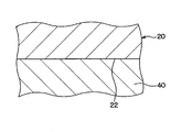
図1における熱交換器の冷却面と接合材との界面の拡大図である。
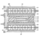
第2実施形態にかかる冷却モジュールを示す概略断面図である。
第3実施形態にかかる冷却モジュールを示す概略断面図である。
以下に、図面を参照しながら本開示を実施するための複数の実施形態を説明する。各実施形態において先行する実施形態で説明した事項に対応する部分には同一の参照符号を付して重複する説明を省略する場合がある。各実施形態において構成の一部のみを説明している場合は、構成の他の部分については先行して説明した実施形態と同様とする。各実施形態で具体的に説明している部分の組合せばかりではなく、特に組合せに支障が生じなければ、実施形態同士を部分的に組み合せることも可能である。
(第1実施形態)
第1実施形態にかかる冷却モジュールS1について、図1を参照して述べる。この冷却モジュールS1は、たとえば自動車などの車両に搭載され、車両用の各種電子装置における電力変換装置等に適用される。
第1実施形態にかかる冷却モジュールS1について、図1を参照して述べる。この冷却モジュールS1は、たとえば自動車などの車両に搭載され、車両用の各種電子装置における電力変換装置等に適用される。
本実施形態の冷却モジュールS1は、発熱体10、熱交換器20および絶縁板30を備える。発熱体10は、駆動時等に発熱する。熱交換器20は、金属製であり、発熱体10と熱交換する。絶縁板30は、発熱体10と熱交換器20との間に介在し、発熱体10と熱交換器20とを電気的に絶縁する。
本実施形態の発熱体10は、いわゆる両面放熱型のモールドパッケージとして構成されている。具体的に、発熱体10は、発熱素子11と、発熱素子11に電気的および熱的に接続されたヒートシンク12と、これら発熱素子11およびヒートシンク12を封止するモールド樹脂13を有している。
発熱素子11は、シリコン半導体等、たとえば発熱素子11は、MOSトランジスタやIGBT等のパワー素子等により構成されている。このような発熱素子11は、通常の半導体プロセス等により、たとえば半導体チップとして形成されている。
ここで、ヒートシンク12は、発熱素子11の表裏両側(図1における発熱素子11の上下両側に相当)それぞれに設けられている。このヒートシンク12は、Cu(銅)やFe(鉄)等の放熱性に優れた金属等で形成され、板状をなし、発熱素子11の放熱板且つ電極として機能する。
発熱素子11における表裏の両側において、ヒートシンク12の一方の板面と発熱素子11とが、はんだ14を介して電気的および機械的に接合されている。このはんだ14は、この種のモールドパッケージに通常採用されるものとすることができ、典型的にはPb(鉛)フリーはんだ等がはんだ14として用いられる。
そして、これらヒートシンク12、発熱素子11、ヒートシンク12が順次積層された積層体が、モールド樹脂13により、包み込まれるように封止されている。このモールド樹脂13は、ポリイミドやエポキシ樹脂等の典型的なモールド材料よりなり、トランスファー成形、コンプレッション成形等により形成される。
ここで、発熱素子11の表裏両側において、ヒートシンク12は、発熱素子11とはんだ接続されている板面とは反対側の板面をモールド樹脂13より露出させている。そして、ヒートシンク12において、このモールド樹脂13から露出する面が、放熱面15とされている。
このように、本実施形態では、発熱体10は、当該発熱体10の表面において2個の放熱面15を有している。駆動時等に発生する発熱素子11の熱は、ヒートシンク12に伝わり、放熱面15を介して、発熱体10の外部に放出される。このように、本実施形態の発熱体10は、発熱素子11の表裏両側、すなわち発熱体10の表裏両側に放熱面15を有しており、上記した両面放熱型のモールドパッケージとして構成されている。
なお、発熱体10は、この種のモールドパッケージと同様に、一部がモールド樹脂13で封止された図示しないリードフレームを備えている。そして、このリードフレームにおけるインナーリードと発熱素子11とがワイヤボンディング等で接続されている。また、このリードフレームにおけるアウターリードは、モールド樹脂13より露出して、外部配線部材等と電気的に接続可能である。
また、図示しないが、ヒートシンク12には、ヒートシンク12に一体に形成された端子部が設けられ、この端子部はモールド樹脂13より露出している。そして、これらリードフレームやヒートシンク12の端子部により、本実施形態の発熱体10は、発熱体10外部、ひいては冷却モジュールS1の外部と電気的に接続可能である。
熱交換器20は、発熱体10と熱交換して発熱体10を冷却する冷却器として機能する。ここでは、熱交換器20は、内部を水やエチレングリコール等の冷媒が流れるもので、いわゆる水冷タイプである。
この熱交換器20は、たとえばAl(アルミニウム)等の熱伝導性に優れ、軽量化等に適した金属で形成される。熱交換器20は、内部に冷媒が流れる流路21を有しており、図示しないタンク等からポンプ等により、冷媒が流路21に供給される。
本実施形態では、熱交換器20は、発熱体10における表裏の2つの放熱面15のそれぞれに対向して設けられている。つまり、本実施形態の冷却モジュールS1は、一対の熱交換器20の間に発熱体10が設けられた積層構成を有する。
この熱交換器20のそれぞれにおいて、発熱体10の放熱面15に対向する面が、放熱面15と熱的に接続される冷却面22とされている。つまり、冷却面22は、放熱面15との間で熱交換して発熱体10を冷却する。
具体的には、熱交換器20は、図1中の上下方向を厚さ方向とし、矩形の主面を表裏に有する薄型の直方体形状を有している。熱交換器20のうち、発熱体10と対向する一方の主面が冷却面22とされている。なお、図1では、熱交換器20における冷却面22とは反対側の主面は、外側面23として示してある。換言すれば、熱交換器20における発熱体10とは反対側の冷却面が外側面23となっている。
絶縁板30は、電気絶縁性且つ熱伝導性を有する板であり、発熱体10の放熱面15と熱交換器20の冷却面22との間の電気絶縁性および熱伝導性を確保する。絶縁板30は、たとえばシリコンナイトライド(SiN)やアルミナ(Al2O3)等のセラミックやガラス等により形成される。また、絶縁板30は、絶縁板30としての電気絶縁性および熱伝導性が確保されるならば、たとえば電気絶縁性の樹脂等により成形されてもよい。
この絶縁板30は、発熱体10の表裏の両側において、放熱面15と熱交換器20の冷却面22との間に介在している。具体的には、絶縁板30は、一面(第1面)および他面(第2面)を表裏に備え、第1面を放熱面15に対向させると共に第2面を冷却面22に対向させた状態で配置されている。換言すれば、絶縁板30は、放熱面15側の第1面および冷却面22側の第2面を有し、放熱面15と冷却面22との間に介在している。また、絶縁板30は、電気絶縁性および熱伝導性を有している。
ここで、熱交換器20の冷却面22と絶縁板30との間には金属製の接合材40が介在し、絶縁板30は接合材40によって冷却面22に一体に接合されている。換言すれば、接合材40は絶縁板30の第2面と冷却面22との間に介在して、絶縁板30を冷却面22に一体的に接合させる。この接合材40は、典型的には、ろう材であるが、はんだ等であってもよい。
たとえば、Al-Cu、Al-Ag、Al-Si等がろう材として用いられ、Cuを含むCu系のはんだ等がはんだとして用いられる。このように、絶縁板30は、冷却面22に対して、ろう付けやはんだ付けにより一体に接合されている。
ここで、このような金属製の接合材40は、2種類の金属から構成される共晶からなるもの、つまり共晶部とされたものであり、図2に示されるように、冷却面22と接合されていることが望ましい。
この共晶部としての接合材40は、冷却面22と接合材40とについて共晶による接合を発現しやすい材料を適宜選択することで接合される。接合材40による共晶部が形成されていると、冷却面22と接合材40とで接合は確保されるので、強固な接合が実現されやすくなる、という利点がある。また、冷却モジュールの壊れ方を考えた場合、この共晶部の存在により、共晶部の脆弱な部分が優先的に破損するので、接合された絶縁板30自身が破損することはなく、漏電による機能停止を防ぐことができる、という利点もある。
具体的に述べると、典型的には、接合材40を構成する金属は、冷却面22すなわち熱交換器20を構成する金属とは異なる金属である。また、共晶とは、共融混合物とも言い、同時に析出する2種以上の結晶の混合物である。
例えば、冷却面22を構成する金属がAlであり、接合材40を構成する金属がAl-Cuである場合には、接合材40を構成する金属はCuである。そして、この場合、共晶部は、Al-Cuの共晶により構成される。また、接合材40を構成する金属がAl-Cuである場合は、接合性の確保等の点から、接合材40による共晶部を形成するθ相の厚さが2μm以下であることが望ましい。なお、絶縁板30と接合材40とは、直接接触した状態で、ろう付けやはんだ付けの形態で接合されていればよい。
また、発熱体10の放熱面15と絶縁板30との間には、接合材40よりも弾性率が低い弾性部材50、すなわち接合材40よりも軟らかい弾性部材50が介在している。これにより、放熱面15と絶縁板30とは、弾性部材50を介して密着している。換言すれば、弾性部材50は、接合材40よりも弾性率が低く、絶縁板30の第1面と放熱面15との間に介在して絶縁板30を放熱面15に密着させる。
さらに言えば、弾性部材50は、接合材40よりも弾性率(あるいはヤング率)が小さく、軟らかく変形しやすい。このような低弾性率の弾性部材50としては、典型的には、シリコーン樹脂等よりなる放熱グリスが挙げられる。なお、弾性部材50は、弾性を有するとともに使用環境耐性を有していれば、ゴム等よりなるシートなどであってもよい。
こうして、本実施形態の冷却モジュールS1は、熱交換器20、絶縁板30、および、発熱体10が、接合材40および弾性部材50を介して積層されている。そして、発熱体10の放熱面15と熱交換器20の冷却面22とは、接合材40、絶縁板30および弾性部材50を介して接触することで、熱的に接続されている。
このような熱的接続構成により、本実施形態では、接合材40、絶縁板30および弾性部材50を介して放熱面15と冷却面22との間で熱交換が行われる。そのため、発熱体10に発生する熱は、絶縁板30を介して熱交換器20に放熱され、発熱体10は冷却される。
ここで、本実施形態の冷却モジュールS1は、熱交換器20、絶縁板30、発熱体10、絶縁板30、熱交換器20が積層された積層構成を有しており、この積層構成は、図示しない箇所にて、ねじ止め等の固定方法等により保持されている。具体的には、積層方向(図1の上下方向に相当)に圧縮される力が印加された状態で、熱交換器20、絶縁板30および発熱体10が積層されている。
冷却モジュールS1の組み付け方法の一例を、次に説明する。まず、熱交換器20の冷却面22に、接合材40を介して絶縁板30を接合し、熱交換器20と絶縁板30とを一体化しておく。
次に、弾性部材50を絶縁板30もしくは発熱体10の放熱面15に配置した状態で、熱交換器20と発熱体10とを積層する。そして、上述のねじ止め等を行い、積層された各部品同士を固定する。こうして、本実施形態の冷却モジュールS1が組み立てられる。
本実施形態によれば、熱交換器20の冷却面22と発熱体10の放熱面15との間の伝熱経路、つまり放熱経路に、電気絶縁性の絶縁板30が介在する。これにより、冷却面22と放熱面15とは電気的に絶縁される。また、当該放熱経路において、冷却面22と絶縁板30との間に介在する金属製の接合材40により、熱抵抗の悪化を抑制することができる。
また、当該放熱経路において、放熱面15と絶縁板30との間に介在する弾性率の低い弾性部材50により、発熱による線膨張係数差に起因して絶縁板30に発生する応力を緩和することができる。従って、熱的接続部分をモールド樹脂で囲う必要がない。
また、弾性部材50は、上記した積層構造を有する冷却モジュールS1に印加されている圧縮力によって放熱面15と絶縁板30とに密着した状態となっている。そのため、たとえば固定手段等による圧縮力を解除することで、発熱体10と絶縁板30とを容易に取り外すことができる。これによれば、たとえば発熱体10の故障等が生じた場合、容易に発熱体10のみを取り替えることができる。
さらには、放熱面15や絶縁板30が凹凸を有していても、これら凹凸は弾性部材50の変形により埋められるため、放熱面15と絶縁板30との密着性が向上する等の利点が期待できる。
よって、本実施形態によれば、熱交換器20の冷却面22と発熱体10の放熱面15との絶縁性を確保しつつ、線膨張差により絶縁板30に発生する応力の緩和、および、熱的接続部分における熱抵抗の悪化の低減を実現することができる。
また、本実施形態によれば、予め熱交換器20と絶縁板30とを一体に接合したうえで、放熱面15と絶縁板30との間に弾性部材50を配置して、発熱体10を組み付けている。そのため、放熱面15と絶縁板30との間、および、絶縁板30と冷却面22との間の両方に、それぞれ放熱グリス等の弾性部材を配置して組み付けを行う場合に比べて、組み付け性の簡素化が期待できる。
本実施形態では、図1に示すように、熱交換器20の表面のうち一面が冷却面22とされ、この冷却面22に絶縁板30が設けられている。冷却面22は、上述したように、発熱体10の放熱面15に対向し、接合材40、絶縁板30、弾性部材50を介して、放熱面15と熱的に接続されている。また、図1において、熱交換器20の表面のうち発熱体10とは反対側に位置し、放熱面15と熱的に接続されない面を外側面23とした。
図1に示されるように、放熱面15と対向していない外側面23に対し、金属製の外側接合材40Aによって絶縁板30が一体に接合されている。換言すれば、外側面23と外側絶縁板30Aとの間に、外側接合材40Aが介在している。
これによれば、熱交換器20の冷却面22と絶縁板30が接合材40により一体に接合され、外側面23と外側絶縁板30Aが外側接合材40Aにより一体に接合されている。外側絶縁板30Aは、絶縁板30と実質的に同一の部材であり、従って、冷却面22および外側面23のどちらに対しても、発熱体10を熱的に接続することが可能となる。
これにより、外側面23を冷却面として機能させることができる。つまり、発熱体10の発熱状況に応じて、冷却面22と外側面23のどちらか一方を冷却面として選択することが可能になる。具体的には、熱交換器20において絶縁板30または外側絶縁板30Aが接合されている冷却面22および外側面23のうち一方を選択して、冷却面22と外側面23のうち当該選択された一方に発熱体10を接続してやればよい。例えば、外側面23に発熱体10を設けた場合には、外側面23が冷却面として機能し、冷却面22が外側面23として機能することになる。また、この外側面23へ外側絶縁板30Aを接合する効果として、熱交換器20の冷却面22と外側面23の反りを低減する効果が期待される。
さらに、本実施形態によれば、熱交換器20における冷却面22および外側面23の両方に発熱体10を熱的に接続することも可能になる。この場合、外側面23も冷却面として機能し、熱交換器20は、表裏に2つの冷却面を有することとなる。
なお、熱交換器20の外側面23を、何も接合されることなく露出した面としてもよい。すなわち、熱交換器20の冷却面22のみに絶縁板30を設けてもよい。
また、図1では、発熱体10の表裏両側が放熱面15とされており、それぞれの放熱面15に対応するように2個の熱交換器20が設けられている。しかしながら、熱交換器20は、2つの放熱面15のうちどちらか一方に対応するように1個設けていてもよい。たとえば、図1において、発熱体10の下側の熱交換器20を省略して、発熱体10における下側の放熱面15を、外気にさらされた状態としてもよい。
(第2実施形態)
第2実施形態にかかる冷却モジュールS2について、図3を参照して、第1実施形態との相違点を中心に述べる。この冷却モジュールS2は、図1に示される、熱交換器20、発熱体10、熱交換器20が交互に積層されてなる積層体100により構成される。
第2実施形態にかかる冷却モジュールS2について、図3を参照して、第1実施形態との相違点を中心に述べる。この冷却モジュールS2は、図1に示される、熱交換器20、発熱体10、熱交換器20が交互に積層されてなる積層体100により構成される。
本実施形態では、発熱体10および熱交換器20の数はそれぞれ2以上である。ここでは、図3に示されるように、発熱体10および熱交換器20の数は、それぞれ3および4である。なお、本実施形態では、複数の熱交換器20と複数の発熱体10とが交互に積層された積層体100が形成されていればよく、発熱体10の個数および熱交換器20の個数は、ともに複数であれば特に限定するものではない。
つまり、複数個の発熱体10は、直列に配列され、隣り合う発熱体10同士のそれぞれの間に熱交換器20が介在するように、複数個の発熱体10および複数個の熱交換器20が交互に積層されて積層体100を形成している。
ここで、放熱面15、冷却面22はそれぞれ、隣り合う発熱体10と熱交換器20とにおいて互いに対向する発熱体10の面、熱交換器20の面とされている。そして、隣り合う発熱体10および熱交換器20同士において、互いに対向する放熱面15と冷却面22との間では、上記第1実施形態と同様、接合材40、絶縁板30および弾性部材50を介した熱的な接続がなされている。
換言すれば、冷却モジュールS2では、複数の発熱体10と複数の熱交換器20とが交互に積層されて積層体100を形成しており、接合材40、絶縁板30および弾性部材50が複数組み設けられている。隣り合う発熱体10および熱交換器20における放熱面15および冷却面22は、一組の接合材40、絶縁板30および弾性部材50を介して熱的に接続されている。
このように、冷却モジュールS2は、発熱体10と熱交換器20とが繰り返して配置された積層体100よりなる。そして、上述のように、図3の例では、3個の発熱体10と4個の熱交換器20とが繰り返し積層されている。
ここで、図3中の上端および下端に位置する2個の熱交換器20以外の、中間の2個の熱交換器20については、上下両側に発熱体10が配置され、当該上下両側にて放熱面15と対向している。そして、図3における当該中間の2個の熱交換器20のそれぞれは、上面と下面の両方が冷却面22とされている。この2つの冷却面22のそれぞれに、接合材40によって絶縁板30が一体に接合されている。
そして、当該2つの冷却面22のそれぞれに接合された絶縁板30と、これに隣り合う発熱体10の放熱面15とが弾性部材50を介して密着している。こうして、本実施形態においても、隣り合う熱交換器20と発熱体10との間で、冷却面22と放熱面15とが熱的に接続されている。
そして、本実施形態の発熱体10においても、図1に示された構成と同様に、発熱体10の2つの放熱面15のそれぞれが、これに隣り合う熱交換器20の冷却面22に対して、接合材40、絶縁板30および弾性部材50を介して熱的に接続され、効率の良い両面放熱を可能としている。
さらに言えば、図3に示される構造においては、上端および下端に位置する2個の熱交換器20は、一面のみが熱交換器20に熱的に接続される冷却面22とされ、外側面23側には発熱体10が配置されない。一方、中間の2個の熱交換器20は、上面と下両の両方が冷却面22とされたものであり、表面のうち2面が冷却面22とされた熱交換器20に相当する。
上述したように、図3においては、中間の2個の熱交換器20は、上面と下両の両方が冷却面22とされており、つまり、2つの冷却面22を有している。しかしながら、この中間の2つの熱交換器20が、冷却面22を1つのみ有してもよい。
たとえば、図3において、中間の2個の熱交換器20のそれぞれについて、上面および下面のいずれか一方のみを冷却面22とすればよい。この場合、冷却面22とこれに対向する発熱体10の放熱面15とを、上記同様に、接合材40、絶縁板30、弾性部材50を介して熱的に接続すればよい。
また、この場合、中間の2個の熱交換器20のそれぞれにおいて、冷却面22とは反対側の面には絶縁板30を設けず、当該反対側の面とこれに対向する発熱体10の放熱面15との間に隙間を形成すればよい。
あるいは、中間の2個の熱交換器20のそれぞれにおいて、当該反対側の面には、接合材40を介して絶縁板30のみ設けて、弾性部材50は設けなくてもよい。この場合、当該反対側の面側において、絶縁板30とこれに対向する発熱体10の放熱面15との間に隙間を形成する。
(第3実施形態)
第3実施形態にかかる冷却モジュールS3について、図4を参照して述べる。本実施形態は、上記第1実施形態と比較して絶縁板30の構成を変形したところが相違するものであり、この相違点を中心に述べる。
第3実施形態にかかる冷却モジュールS3について、図4を参照して述べる。本実施形態は、上記第1実施形態と比較して絶縁板30の構成を変形したところが相違するものであり、この相違点を中心に述べる。
第1実施形態では、絶縁板30は、セラミックやガラス等よりなる単一の板として構成されている。これに対して、本実施形態では、発熱体10の放熱面15と熱交換器20の冷却面22との間に介在する絶縁板30Bは、セラミックやガラス等により形成される絶縁層30bと、この絶縁層30bにおける冷却面22側の面に積層された金属層30aの2層が積層された積層構造を有している。具体的には、図4に示されるように、絶縁板30Bの表裏の板面のうち冷却面22に対向する面が金属層30aとなっている。
本実施形態においても、絶縁板30Bが電気絶縁性の絶縁層30bを有するため、熱交換器20の冷却面22と発熱体10の放熱面15との間の電気絶縁が確保される。
この金属層30aは、ろう材やはんだ等よりなる接合材40との接合性に優れた金属、具体的には、銅やアルミニウム等の金属により形成される。そして、この金属層30aは、絶縁層30bの表面にスパッタ、蒸着、めっき、あるいは、ロウ付け等の成膜法により設けられ、絶縁板30Bにおいて冷却面22側の面を構成している。
そして、本実施形態では、熱交換器20の冷却面22と絶縁板30Bの金属層30aとの間に、接合材40が介在している。接合材40は、絶縁板30と冷却面22とを一体的に接合している。一方、第1実施形態同様、発熱体10の放熱面15と絶縁板30Bの絶縁層30bとが弾性部材50を介して密着している。
本実施形態では、絶縁板30Bのうち接合材40が配置される冷却面22側に金属層30aを設け、この金属層30aと接合材40とを接合するようにしているため、接合性の向上が期待できる。つまり、接合材40による接合対象として、絶縁層30bよりもろう付けやはんだ付け性に優れた金属層30aが用いられることで、接合強度の向上が図れる。
図3の例では、絶縁板30Bは、熱交換器20の冷却面22側のみに金属層30aを有している。しかしながら、さらに発熱体10の放熱面15側にも金属層30aを有してもよい。
この場合、図示しないが、絶縁板30Bは、発熱体10側から熱交換器20側へ向かって、金属層30a、絶縁層30b、金属層30aが積層された3層構成となる。このような3層構成の場合、絶縁層30bの両側に金属層30aが積層されているため、2層構成に比べて、絶縁板30がさらに反りにくくなるという効果が期待できる。
なお、本実施形態においても、図1と同様、熱交換器20の外側面23に外側絶縁板30Aを設けており、この外側面23に接続された外側絶縁板30Aは、第1実施形態と同様、単一の板として構成されている。しかし、この外側絶縁板30Aも、絶縁板30Bのような積層構成を有していてもよい。
また、本実施形態においても、熱交換器20の外側面23は、何も接合されることなく露出した面としてもかまわない。また、本実施形態においても、発熱体10の表裏両側の放熱面15のどちらか一方のみに対して、熱交換器20を設けてもよい。つまり、図4における上下2つの放熱面15のうち一方にて熱交換器20を省略し、当該一方の放熱面15を外気にさらした構成としてもよい。
さらに、本実施形態は、絶縁板30Bが金属層30aと絶縁層30bを積層してなる積層構成を有する点のみが他の実施形態と異なる。従って、第2実施形態のように、複数の発熱体10と複数の熱交換器20とが交互に積層されてなる積層体100により構成される冷却モジュールS2に、本実施形態の絶縁板30Bを採用してもよい。
以上、本開示の好ましい実施形態について説明したが、本開示は上述した実施形態に何ら制限されることなく、本開示の主旨を逸脱しない範囲において種々変形して実施することが可能である。上記実施形態の構造は、あくまで例示であって、本開示の範囲はこれらの記載の範囲に限定されるものではない。本開示の範囲は、本開示における記載と均等の意味及び範囲内での全ての変更を含む。
(他の実施形態)
上述した各実施形態においては、発熱体10は、発熱素子11の表裏両側に放熱面15を有する両面放熱タイプのものであった。しかしながら、発熱体10は、発熱素子11の表裏両側のうち一方側のみに放熱面15を有してもよい。例えば、図1に示される発熱体10において、一方のヒートシンク12を省略したパッケージ構成とすればよい。
上述した各実施形態においては、発熱体10は、発熱素子11の表裏両側に放熱面15を有する両面放熱タイプのものであった。しかしながら、発熱体10は、発熱素子11の表裏両側のうち一方側のみに放熱面15を有してもよい。例えば、図1に示される発熱体10において、一方のヒートシンク12を省略したパッケージ構成とすればよい。
また、発熱体10としては、表面の少なくとも一面が放熱面15とされているものであればよく、上記したモールドパッケージに限定されるものではない。たとえば、配線基板の一面側に発熱素子が搭載され、配線基板の他面側を放熱面とする電子装置等であってもよい。
また、熱交換器20は、表面の少なくとも一面が冷却面22とされたものであればよく、1つの熱交換器20について3面以上の冷却面22が設けられていてもよい。また、熱交換器20としては、上記した水冷式に限らず、たとえば空冷式のフィン構造体などであってもよい。
また、本開示は上記した実施形態に限定されるものではなく、本開示の趣旨を逸脱しない範囲内において適宜変更が可能である。また、上記各実施形態は、互いに無関係なものではなく、組み合わせが明らかに不可な場合を除き、適宜組み合わせが可能であり、また、上記各実施形態は、上記の図示例に限定されるものではない。
Claims (7)
- 表面の少なくとも一面が放熱面(15)とされた発熱体(10)と、
表面の少なくとも一面が前記放熱面に対向する冷却面(22)とされた金属製の熱交換器(20)と、
第1面および第2面を表裏に備え、前記放熱面に対向すると共に前記第2面が前記冷却面に対向した状態で前記放熱面と前記冷却面との間に介在し、電気絶縁性および熱伝導性を有する絶縁板(30、30A、30B)と、を備え、
前記発熱体が発生した熱は、前記絶縁板を介して前記放熱面と前記冷却面との間で熱交換されることにより前記熱交換器に放出され、
前記冷却面と前記絶縁板との間には金属製の接合材(40)が介在し、前記絶縁板は前記接合材によって前記冷却面に一体に接合されており、
前記放熱面と前記絶縁板とは、前記接合材よりも弾性率が低い弾性部材(50)を介して密着しており、
前記放熱面と前記冷却面とは、前記接合材、前記絶縁板および前記弾性部材を介して熱的に接続されている冷却モジュール。 - 熱を放出する放熱面(15)を有する発熱体(10)と、
前記発熱体を冷却する冷却面(22)を有する金属製の熱交換器(20)と、
前記放熱面側の第1面および前記冷却面側の第2面を有し、前記放熱面と前記冷却面との間に介在する電気絶縁性および熱伝導性を有した絶縁板(30、30A、30B)と、
前記第2面と前記冷却面との間に介在して、前記絶縁板を前記冷却面に一体的に接合させる金属製の接合材(40)と、
前記接合材よりも弾性率が低く、前記第1面と前記放熱面との間に介在して前記絶縁板を前記放熱面に密着させる弾性部材(50)と、を備え、
前記発熱体が発生した熱は、前記絶縁板を介して前記熱交換器に放出され、
前記放熱面および前記冷却面は、前記接合材、前記絶縁板および前記弾性部材を介して熱的に接続されている冷却モジュール。 - 前記接合材が少なくとも2種類の金属から構成される共晶からなる請求項1または2に記載の冷却モジュール。
- 一対の前記熱交換器(20)の間に前記発熱体(10)が設けられ、
前記熱交換器における前記発熱体(10)とは反対側の外側面(23)に外側絶縁板(30A)が設けられ、
前記外側絶縁板は、金属製の外側接合材(40A)によって前記外側面に一体的に接合されている請求項1ないし3のいずれか1つに記載の冷却モジュール。 - 複数の前記発熱体と複数の前記熱交換器とが交互に積層されて積層体(100)を形成し、
前記接合材、前記絶縁板および前記弾性部材が複数組み設けられ、
隣り合う前記発熱体および前記熱交換器における前記放熱面および前記冷却面は、一組の前記接合材、前記絶縁板および前記弾性部材を介して熱的に接続されている請求項1ないし4のいずれか1つに記載の冷却モジュール。 - 前記接合材は、Al-Cu、Al-Ag、Al-Siのいずれか1つにより構成される請求項3に記載の冷却モジュール。
- 前記接合材は、Al-Cuで構成されており、前記接合材による共晶部を形成するθ相の厚さが2μm以下である請求項6に記載の冷却モジュール。
Priority Applications (3)
| Application Number | Priority Date | Filing Date | Title |
|---|---|---|---|
| DE112015005267.4T DE112015005267T5 (de) | 2014-11-20 | 2015-11-13 | Kühlmodul |
| CN201580057871.XA CN107112300B (zh) | 2014-11-20 | 2015-11-13 | 冷却组件 |
| US15/520,486 US10253729B2 (en) | 2014-11-20 | 2015-11-13 | Cooling module |
Applications Claiming Priority (4)
| Application Number | Priority Date | Filing Date | Title |
|---|---|---|---|
| JP2014235448 | 2014-11-20 | ||
| JP2014-235448 | 2014-11-20 | ||
| JP2015120462A JP6409690B2 (ja) | 2014-11-20 | 2015-06-15 | 冷却モジュール |
| JP2015-120462 | 2015-06-15 |
Publications (1)
| Publication Number | Publication Date |
|---|---|
| WO2016079970A1 true WO2016079970A1 (ja) | 2016-05-26 |
Family
ID=56013543
Family Applications (1)
| Application Number | Title | Priority Date | Filing Date |
|---|---|---|---|
| PCT/JP2015/005683 Ceased WO2016079970A1 (ja) | 2014-11-20 | 2015-11-13 | 冷却モジュール |
Country Status (1)
| Country | Link |
|---|---|
| WO (1) | WO2016079970A1 (ja) |
Cited By (1)
| Publication number | Priority date | Publication date | Assignee | Title |
|---|---|---|---|---|
| JP2018041824A (ja) * | 2016-09-07 | 2018-03-15 | トヨタ自動車株式会社 | 半導体装置 |
Citations (4)
| Publication number | Priority date | Publication date | Assignee | Title |
|---|---|---|---|---|
| JP2007165620A (ja) * | 2005-12-14 | 2007-06-28 | Denso Corp | 半導体冷却構造 |
| JP2012178513A (ja) * | 2011-02-28 | 2012-09-13 | Mitsubishi Materials Corp | パワーモジュールユニット及びパワーモジュールユニットの製造方法 |
| JP2012231113A (ja) * | 2011-04-13 | 2012-11-22 | Denso Corp | 窒素とアルミニウムと他金属とを含む多元化合物の複合材料、その製造方法、絶縁フィルム、絶縁接着剤及び熱交換器 |
| JP2015153869A (ja) * | 2014-02-13 | 2015-08-24 | 三菱マテリアル株式会社 | 絶縁層付冷却器、およびその製造方法、冷却器付パワーモジュール |
-
2015
- 2015-11-13 WO PCT/JP2015/005683 patent/WO2016079970A1/ja not_active Ceased
Patent Citations (4)
| Publication number | Priority date | Publication date | Assignee | Title |
|---|---|---|---|---|
| JP2007165620A (ja) * | 2005-12-14 | 2007-06-28 | Denso Corp | 半導体冷却構造 |
| JP2012178513A (ja) * | 2011-02-28 | 2012-09-13 | Mitsubishi Materials Corp | パワーモジュールユニット及びパワーモジュールユニットの製造方法 |
| JP2012231113A (ja) * | 2011-04-13 | 2012-11-22 | Denso Corp | 窒素とアルミニウムと他金属とを含む多元化合物の複合材料、その製造方法、絶縁フィルム、絶縁接着剤及び熱交換器 |
| JP2015153869A (ja) * | 2014-02-13 | 2015-08-24 | 三菱マテリアル株式会社 | 絶縁層付冷却器、およびその製造方法、冷却器付パワーモジュール |
Cited By (1)
| Publication number | Priority date | Publication date | Assignee | Title |
|---|---|---|---|---|
| JP2018041824A (ja) * | 2016-09-07 | 2018-03-15 | トヨタ自動車株式会社 | 半導体装置 |
Similar Documents
| Publication | Publication Date | Title |
|---|---|---|
| JP6409690B2 (ja) | 冷却モジュール | |
| CN100578768C (zh) | 散热装置及功率模块 | |
| JP6199397B2 (ja) | 半導体装置およびその製造方法 | |
| JP6257478B2 (ja) | 電力用半導体装置 | |
| WO2007145303A1 (ja) | 半導体モジュールおよびその製造方法 | |
| JP2007173680A (ja) | 半導体装置 | |
| TWI758579B (zh) | 附散熱座功率模組用基板及功率模組 | |
| CN101789404A (zh) | 散热器 | |
| JP2011159662A (ja) | 半導体装置 | |
| CN103378024A (zh) | 散热装置及其制造方法 | |
| JP6503796B2 (ja) | ヒートシンク付パワーモジュール用基板及びパワーモジュール | |
| JP2009200258A (ja) | 半導体モジュール | |
| JP2007081200A (ja) | 冷却シンク部付き絶縁回路基板 | |
| JP4935783B2 (ja) | 半導体装置および複合半導体装置 | |
| WO2016042903A1 (ja) | 半導体モジュール | |
| JP2016134586A (ja) | パワー半導体モジュール | |
| JP6555159B2 (ja) | 冷却チューブ | |
| WO2016079970A1 (ja) | 冷却モジュール | |
| JP4158648B2 (ja) | 半導体冷却ユニット | |
| JP4193633B2 (ja) | 半導体冷却ユニット | |
| JP2016092222A (ja) | 半導体装置 | |
| JP7166150B2 (ja) | 冷却器、そのベース板および半導体装置 | |
| JP5320354B2 (ja) | 放熱装置 | |
| JP5365529B2 (ja) | パワーモジュール | |
| JP5206330B2 (ja) | パワーモジュール |
Legal Events
| Date | Code | Title | Description |
|---|---|---|---|
| 121 | Ep: the epo has been informed by wipo that ep was designated in this application |
Ref document number: 15860599 Country of ref document: EP Kind code of ref document: A1 |
|
| WWE | Wipo information: entry into national phase |
Ref document number: 15520486 Country of ref document: US |
|
| WWE | Wipo information: entry into national phase |
Ref document number: 112015005267 Country of ref document: DE |
|
| 122 | Ep: pct application non-entry in european phase |
Ref document number: 15860599 Country of ref document: EP Kind code of ref document: A1 |