WO2016076164A1 - 非偏光部を有する偏光子の製造方法 - Google Patents
非偏光部を有する偏光子の製造方法 Download PDFInfo
- Publication number
- WO2016076164A1 WO2016076164A1 PCT/JP2015/080993 JP2015080993W WO2016076164A1 WO 2016076164 A1 WO2016076164 A1 WO 2016076164A1 JP 2015080993 W JP2015080993 W JP 2015080993W WO 2016076164 A1 WO2016076164 A1 WO 2016076164A1
- Authority
- WO
- WIPO (PCT)
- Prior art keywords
- polarizer
- polarizing
- liquid
- basic solution
- polarizing film
- Prior art date
Links
Images


Classifications
-
- B—PERFORMING OPERATIONS; TRANSPORTING
- B32—LAYERED PRODUCTS
- B32B—LAYERED PRODUCTS, i.e. PRODUCTS BUILT-UP OF STRATA OF FLAT OR NON-FLAT, e.g. CELLULAR OR HONEYCOMB, FORM
- B32B38/00—Ancillary operations in connection with laminating processes
- B32B38/12—Deep-drawing
-
- G—PHYSICS
- G02—OPTICS
- G02B—OPTICAL ELEMENTS, SYSTEMS OR APPARATUS
- G02B5/00—Optical elements other than lenses
- G02B5/30—Polarising elements
-
- G—PHYSICS
- G02—OPTICS
- G02B—OPTICAL ELEMENTS, SYSTEMS OR APPARATUS
- G02B1/00—Optical elements characterised by the material of which they are made; Optical coatings for optical elements
- G02B1/10—Optical coatings produced by application to, or surface treatment of, optical elements
- G02B1/14—Protective coatings, e.g. hard coatings
-
- G—PHYSICS
- G02—OPTICS
- G02B—OPTICAL ELEMENTS, SYSTEMS OR APPARATUS
- G02B5/00—Optical elements other than lenses
- G02B5/30—Polarising elements
- G02B5/3025—Polarisers, i.e. arrangements capable of producing a definite output polarisation state from an unpolarised input state
- G02B5/3033—Polarisers, i.e. arrangements capable of producing a definite output polarisation state from an unpolarised input state in the form of a thin sheet or foil, e.g. Polaroid
- G02B5/3041—Polarisers, i.e. arrangements capable of producing a definite output polarisation state from an unpolarised input state in the form of a thin sheet or foil, e.g. Polaroid comprising multiple thin layers, e.g. multilayer stacks
-
- B—PERFORMING OPERATIONS; TRANSPORTING
- B32—LAYERED PRODUCTS
- B32B—LAYERED PRODUCTS, i.e. PRODUCTS BUILT-UP OF STRATA OF FLAT OR NON-FLAT, e.g. CELLULAR OR HONEYCOMB, FORM
- B32B2551/00—Optical elements
Definitions
- the present invention relates to a method for manufacturing a polarizer having a non-polarizing portion.
- Some image display devices such as mobile phones and notebook personal computers (PCs) are equipped with internal electronic components such as cameras.
- Various studies have been made for the purpose of improving the camera performance and the like of such an image display device (for example, Patent Documents 1 to 6).
- Patent Documents 1 to 6 For example, Patent Documents 1 to 6
- smartphones and touch panel type information processing devices further improvements in camera performance and the like are desired.
- a polarizing plate partially having polarization performance.
- the present invention has been made to solve the above-described conventional problems, and a main object thereof is to provide a manufacturing method capable of efficiently manufacturing a polarizer having a high-quality non-polarizing portion.
- the manufacturing method of the polarizer which has a non-polarization part of the present invention is provided with a polarizer and a surface protection film arranged on one side of the polarizer, and has an exposed part where the polarizer is exposed on the one side.
- the liquid is the same basic solution as the basic solution.
- the liquid is brought into contact with one surface side of the polarizing film laminate using a nozzle that ejects the liquid.
- the liquid is sprayed linearly onto the exposed portion.
- the exposed portion is arranged in a pattern having a repeating unit, and the liquid is sprayed linearly onto the exposed portion for each repeating unit.
- Polarizing film laminate having a polarizer and a surface protective film disposed on one side of the polarizer, and having an exposed portion where the polarizer is exposed on the one side for the purpose of performing wet treatment only on a desired portion
- a wet process may be performed using a body.
- the immersion to the process liquid using the elongate laminated body is performed as a wet process.
- air may enter the exposed portion when the polarizing film laminate is transported into the treatment liquid, and bubbles may be embraced. Bubbles taken into the exposed portion can adhere to the bottom or wall surface of the exposed portion.
- the method of manufacturing a quality polarizer is improved, improving manufacturing efficiency.
- the bottom and wall surface of the exposed portion can be moistened by bringing the liquid into contact with the polarizing film laminate before immersing the polarizing film laminate in the basic solution. Embrace can be suppressed. As a result, it is possible to efficiently produce a polarizer having a high-quality non-polarizing part even when immersion treatment is performed using a polarizing film laminate having an exposed part. Conventionally, when the production efficiency of a polarizer having a non-polarizing portion is improved by using immersion in a basic solution, the quality may be deteriorated due to decoloration failure caused by embedding bubbles. However, in the manufacturing method of the present invention, since the entrapment of bubbles itself is suppressed, a polarizer having a high-quality non-polarizing portion can be efficiently manufactured.
- FIG. 1 It is a schematic sectional drawing of the polarizing film laminated body used by one Embodiment of this invention. It is a schematic perspective view of the polarizing film laminated body used by one Embodiment of this invention. It is a schematic perspective view explaining bonding of the surface protection film and polarizing plate in the manufacturing method of the polarizer by one embodiment of the present invention. It is the schematic which shows the liquid contact process to the exposed part of the polarizing film laminated body performed by one Embodiment of this invention, and the immersion process to the basic solution of a polarizing film laminated body. It is a schematic partial enlarged view which shows the liquid contact process to the exposed part of the polarizing film laminated body of FIG.
- the manufacturing method of the polarizer which has a non-polarization part of the present invention is provided with a polarizer and a surface protection film arranged on one side of the polarizer, and has an exposed part where the polarizer is exposed on the one side.
- immersion is performed using a polarizing film laminate having an exposed portion, air enters the exposed portion when the polarizing film laminate is transported into the basic solution, and bubbles may be embraced. Since the portion to which the bubbles are attached cannot be sufficiently brought into contact with the basic solution, poor decolorization may occur.
- the characteristics such as the transmittance of the non-polarizing part become insufficient, and the quality can be lowered.
- the polarization of the high-quality non-polarizing portion is suppressed.
- the child can be manufactured efficiently.
- the polarizer before forming a non-polarization part is an intermediate body of the polarizer which has a non-polarization part obtained by the manufacturing method of this invention strictly, it is only called a polarizer in this specification. A person skilled in the art can easily understand from the description of the present specification whether "polarizer” means an intermediate or a polarizer having a non-polarization part obtained by the production method of the present invention. be able to.
- A. Process for Producing Polarized Film Laminate In the method for producing a polarizer of the present invention, an exposed portion comprising a polarizer and a surface protective film disposed on one side of the polarizer, and the polarizer exposed on the one side. Immersion in a basic solution is performed using a polarizing film laminate having the following. Since this polarizing film laminate has an exposed portion where the polarizer is exposed, only the exposed portion of the polarizer comes into contact with the basic solution in the immersion treatment.
- FIG. 1 is a schematic cross-sectional view of a polarizing film laminate used in one embodiment of the present invention.
- the polarizing film laminate 100 is long and has a surface protective film (hereinafter also referred to as a first surface protective film) 50 having a through hole 61, a polarizer 10, a protective film 20, and a second surface protective member.
- the film 30 is provided in this order.
- the surface protection films 50 and 30 are laminated via an adhesive layer (not shown) made of any appropriate adhesive.
- a polarizing plate including a polarizer 10 and a protective film 20 that protects the polarizer 10 is used.
- a polarizer having a form other than the form of a polarizing plate for example, a single resin film
- a certain polarizer, a resin substrate / polarizer laminate may be used.
- the polarizing film laminate 100 has an exposed portion 51 where the polarizer 10 is exposed from the through hole 61 on the side where the surface protective film 50 is disposed.
- the “elongate shape” means an elongated shape having a sufficiently long length with respect to the width, for example, an elongated shape having a length of 10 times or more, preferably 20 times or more with respect to the width. Includes shape.
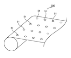
- FIG. 2 is a schematic perspective view of a polarizing film laminate according to one embodiment of the present invention.
- the exposed portions 51 can be arranged in a predetermined pattern.
- the exposed portions 51 are preferably arranged in a pattern having repeating units.
- “arranged in a pattern having a repeating unit” means that the film is arranged in the same pattern for each predetermined length in the longitudinal direction of the polarizing film laminate.
- the exposed portion 51 can be disposed along at least the longitudinal direction.
- the exposed portions 51 can be arranged at substantially equal intervals in the longitudinal direction and / or the width direction. In the illustrated example, the exposed portions 51 are arranged at substantially equal intervals in both the longitudinal direction and the width direction.
- substantially equidistant in both the longitudinal direction and the width direction means that the spacing in the longitudinal direction is equal and the spacing in the width direction is equal.
- the interval in the scale direction and the interval in the width direction need not be equal.
- L1 L2 may be satisfied, or L1 ⁇ L2. Since the exposed portion 51 is arranged in a pattern having a repeating unit, the liquid can be brought into contact with the plurality of exposed portions in the same pattern for each repeating unit, so that the inclusion of bubbles can be more efficiently suppressed. Can do. As a result, the manufacturing efficiency of a polarizer having a non-polarizing part is further improved.
- the polarizing film laminate 100 can be produced by laminating a long surface protective film 50 on the surface of the long polarizer 10.
- FIG. 3 is a schematic perspective view illustrating the bonding of the surface protective film and the polarizing plate in the method for producing a polarizer using the surface protective film according to one embodiment of the present invention.
- a polarizing film laminate is produced using a surface protective film having a long polarizer and a long pressure-sensitive adhesive layer.
- a polarizing film laminate can be produced by roll-to-roll as shown in FIG.
- the elongate 2nd surface protection film 30 can be laminated
- the second surface protective film may be bonded together with the surface protective film having the through hole, or may be bonded before the surface protective film having the through hole is bonded, and the surface protective film having the through hole is bonded. You may bond together after bonding. It goes without saying that the same procedure can be applied to a polarizer having a form other than that of the polarizing plate (for example, a polarizer that is a single resin film, a laminate of a resin base material / polarizer).
- the polarizer is typically composed of a resin film.
- the resin film is typically a polyvinyl alcohol resin (hereinafter referred to as “PVA resin”) film containing a dichroic substance such as iodine or an organic dye.
- PVA resin polyvinyl alcohol resin
- the resin film (typically, PVA resin film) constituting the polarizer may be a single film, or a resin layer (typically, PVA resin layer) formed on the resin substrate. ).
- a polarizer containing iodine is preferable.
- the polarizer contains iodine as a dichroic substance, it is possible to reduce the iodine concentration in the exposed portion by immersion in a basic solution described later, and as a result, selectively form a non-polarizing portion only in the exposed portion. it can. Therefore, a non-polarizing part can be selectively formed in a predetermined part of the polarizer with very high production efficiency without complicated operation.
- the polarizer can be produced by any appropriate method.
- the polarizer can be produced by a method well known and commonly used in the art.
- the polarizer is a PVA resin layer formed on a resin base material, the polarizer can be produced, for example, by the method described in JP 2012-73580 A. This publication is incorporated herein by reference in its entirety.
- the thickness of the polarizer can be set to any appropriate value.
- the thickness is preferably 30 ⁇ m or less, more preferably 25 ⁇ m or less, still more preferably 20 ⁇ m or less, and particularly preferably less than 10 ⁇ m.
- the thickness is preferably 0.5 ⁇ m or more, more preferably 1 ⁇ m or more. With such a thickness, a polarizer having excellent durability and optical characteristics can be obtained.
- the thinner the thickness the better the non-polarizing part can be formed. For example, the contact time between the basic solution and the resin film (polarizer) can be shortened.
- a protective film is bonded to one side or both sides of a polarizer which is a single resin film.
- a protective film is bonded to the polarizer surface of the resin base material / polarizer laminate, the resin base material is then peeled off, and further separated from the release surface of the resin base material as necessary.
- the protective film can be bonded.
- the term “protective film” means a polarizer protective film as described above, and is different from a surface protective film (a film that temporarily protects a polarizing plate during operation). Bonding of the protective film can be typically performed by roll-to-roll.
- Examples of the material for forming the protective film include cellulose resins such as diacetyl cellulose and triacetyl cellulose, (meth) acrylic resins, cycloolefin resins, olefin resins such as polypropylene, and ester resins such as polyethylene terephthalate resins. , Polyamide resins, polycarbonate resins, and copolymer resins thereof.
- the thickness of the protective film is preferably 10 ⁇ m to 100 ⁇ m.
- the protective film is typically laminated on the polarizer via an adhesive layer (specifically, an adhesive layer or an adhesive layer).
- the adhesive layer is typically formed of a PVA adhesive or an activated energy ray curable adhesive.
- the pressure-sensitive adhesive layer is typically formed of an acrylic pressure-sensitive adhesive.
- the polarizing plate may further have any appropriate optical function layer depending on the purpose.
- Representative examples of the optical functional layer include a retardation film (optical compensation film) and a surface treatment layer.
- the surface protective film 50 is provided with a through hole 61 corresponding to a position where a non-polarizing portion of a polarizer (polarizer intermediate) is formed.
- the surface protective film is a laminate having any appropriate resin film and an adhesive layer provided on one surface of the resin film, and the resin film and the adhesive layer Has a through hole.
- the through holes 61 of the surface protective film 50 can be arranged at substantially equal intervals in both the longitudinal direction and the width direction (FIG. 3).
- the through holes 61 may be arranged at substantially equal intervals in the length direction and at different intervals in the width direction; they are arranged at different intervals in the length direction and substantially in the width direction. In general, they may be arranged at equal intervals (both not shown).
- the through holes are arranged at different intervals in the longitudinal direction or the width direction, the intervals between the adjacent through holes may be all different, or only a part (the interval between specific adjacent through holes) may be different. Good.
- a plurality of regions may be defined in the longitudinal direction of the surface protection film 50, and the interval between the through holes 61 in the longitudinal direction and / or the width direction may be set for each region.
- the non-polarizing portions can be arranged at substantially equal intervals in both the long direction and the width direction. With such a configuration, it is easy to control the cutting of the polarizer to a predetermined size in accordance with the size of the image display device, and the yield can be improved.
- the position of the non-polarizing part can be set accurately, the position of the non-polarizing part in the obtained polarizer of a predetermined size can be controlled well. As a result, since the variation in the position of the non-polarizing portion for each obtained polarizer of a predetermined size is reduced, it is possible to obtain a polarizer of a predetermined size with no quality variation.
- the through hole 61 has a straight line connecting adjacent through holes in the longitudinal direction substantially parallel to the longitudinal direction, and a straight line connecting adjacent through holes in the width direction. Are arranged so as to be substantially parallel to the width direction.
- the through-hole 61 has a straight line connecting adjacent through holes in the longitudinal direction substantially parallel to the longitudinal direction, and a straight line connecting adjacent through-holes in the width direction. Are arranged to have a predetermined angle ⁇ W with respect to the width direction.
- the through hole 61 has a straight line connecting through holes adjacent in the longitudinal direction having a predetermined angle ⁇ L with respect to the longitudinal direction, and the through holes adjacent in the width direction.
- ⁇ W is preferably more than 0 ° and not more than ⁇ 10 °.
- ⁇ means to include both clockwise and counterclockwise directions with respect to the reference direction (long direction or width direction).
- the non-polarizing parts in the longitudinal direction and / or the width direction are cut.
- the interval can be changed according to the size of the polarizer to be cut.
- the direction of the absorption axis of the cut polarizer (for example, cutting in the longitudinal direction and / or the width direction, punching) can be precisely controlled to a desired angle, and for each polarizer. Variation in the direction of the absorption axis can be remarkably suppressed. It goes without saying that the arrangement pattern of the through holes is not limited to the illustrated example.
- a straight line connecting adjacent through holes in the longitudinal direction has a predetermined angle ⁇ L with respect to the long direction, and a straight line connecting adjacent through holes in the width direction is It may be arranged to be substantially parallel to the direction. Further, a plurality of regions may be defined in the longitudinal direction of the surface protective film 50, and ⁇ L and / or ⁇ W may be set for each region.
- plan view shape of the through hole of the first surface protective film can be adopted as the plan view shape of the through hole of the first surface protective film depending on the purpose.
- Specific examples include a circle, an ellipse, a square, a rectangle, and a rhombus.
- the through hole of the first surface protective film is formed by, for example, mechanical punching (for example, punching, engraving blade punching, plotter, water jet) or removal of a predetermined portion of the first surface protective film (for example, laser ablation or chemical Dissolution).
- the first surface protective film is preferably a film having high hardness (for example, elastic modulus). This is because the deformation of the through-hole during conveyance and / or bonding can be prevented.
- Surface protective film forming materials include ester resins such as polyethylene terephthalate resins, cycloolefin resins such as norbornene resins, olefin resins such as polypropylene, polyamide resins, polycarbonate resins, and copolymer resins thereof. Etc. Preference is given to ester resins (especially polyethylene terephthalate resins). Such a material has an advantage that the elastic modulus is sufficiently high and deformation of the through-hole hardly occurs even when tension is applied during conveyance and / or bonding.
- the thickness of the first surface protective film is preferably 20 ⁇ m to 250 ⁇ m, more preferably 30 ⁇ m to 150 ⁇ m. If the thickness of the surface protective film is within the above range, the inclusion of bubbles when the polarizing film laminate is transported to the treatment liquid is suppressed, and even if tension is applied during transportation and / or lamination, the through-holes are not affected. Deformation can also be suppressed.
- the elastic modulus of the first surface protective film is preferably 2.2 kN / mm 2 to 4.8 kN / mm 2 . If the elastic modulus is within the above range, the inclusion of bubbles when the polarizing film laminate is transported to the treatment liquid is suppressed, and deformation of the through-hole is prevented even when tension is applied during transportation and / or lamination. Can be suppressed.
- the elastic modulus is measured according to JIS K 6781.
- the tensile elongation of the first surface protective film is preferably 90% to 170%. If the tensile elongation of the surface protective film is within the above range, the inclusion of bubbles when the polarizing film laminate is transported to the treatment liquid is suppressed, and breakage of the film being transported can be prevented.
- the tensile elongation is measured according to JIS K 6781.
- the polarizing film laminate 100 may include the second surface protective film 30 on the side where the surface protective film is not disposed.
- the second surface protective film a film similar to the surface protective film can be used except that no through hole is provided.
- a soft (eg, low elastic modulus) film such as a polyolefin (eg, polyethylene) film can be used.
- the polarizing plate can be further appropriately protected. Specifically, when immersed in a basic solution, the polarizing plate (polarizer / protective film) can be further appropriately protected, and as a result, the non-polarizing part can be formed more satisfactorily. .
- any appropriate pressure-sensitive adhesive layer can be adopted as long as the effects of the present invention can be obtained.
- the base resin for the pressure-sensitive adhesive include acrylic resins, styrene resins, and silicone resins. Acrylic resins are preferred from the viewpoints of chemical resistance, adhesion for preventing the treatment liquid from entering during immersion, flexibility in the adherend, and the like.
- the pressure-sensitive adhesive may contain a crosslinking agent, and examples of the crosslinking agent that can be included in the pressure-sensitive adhesive include isocyanate compounds, epoxy compounds, and aziridine compounds.
- the pressure-sensitive adhesive may contain, for example, a silane coupling agent. The formulation of the pressure-sensitive adhesive can be appropriately set according to the purpose.
- the pressure-sensitive adhesive layer can be formed by any appropriate method. Specific examples include a method of applying a pressure-sensitive adhesive solution on a resin film and drying, a method of forming a pressure-sensitive adhesive layer on a separator, and transferring the pressure-sensitive adhesive layer to the resin film. Examples of the coating method include roll coating methods such as reverse coating and gravure coating, spin coating methods, screen coating methods, fountain coating methods, dipping methods, and spray methods.
- the thickness of the pressure-sensitive adhesive layer is preferably 5 ⁇ m to 60 ⁇ m, more preferably 5 ⁇ m to 30 ⁇ m. If the thickness is too thin, the adhesiveness becomes insufficient, and bubbles or the like may enter the adhesive interface. If the thickness is too thick, problems such as sticking out of the adhesive easily occur.
- the thickness of the pressure-sensitive adhesive layer can be adjusted together with the thickness of the resin film so that the thickness of the surface protective film falls within the above range.
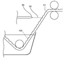
- FIG. 4 is a schematic view showing a liquid contact process to the exposed portion of the polarizing film laminate and an immersion process of the polarizing film laminate in a basic solution performed according to one embodiment of the present invention.
- FIG. 5 and FIG. 6 are schematic enlarged views showing a liquid contact process with the exposed portion of the polarizing film laminate of FIG.
- the liquid 90 is brought into contact with the side of the polarizing film laminate 100 on which the surface protective film 50 is disposed.
- Arbitrary appropriate aspects can be employ
- the aspect which sprays the liquid 90 on the polarizing film laminated body 100 is mentioned.
- the polarizing film laminate 100 is conveyed to the basic solution so that the exposed portion 51 faces downward. That is, the side of the polarizing film laminate 100 on which the surface protective film 50 is disposed is the lower side of the polarizing film laminate 100. Therefore, in the illustrated example, the liquid 90 is sprayed from the lower side of the polarizing film laminate 100.
- any appropriate liquid can be used as the liquid 90.
- the liquid 90 include the same basic solution as the basic solution in which the polarizing film laminate 100 is immersed.
- a basic solution in a basic solution tank in which the polarizing film laminate 100 is immersed is supplied as a liquid 90 by a pump 70.
- the concentration of the liquid in contact with the exposed portion does not change before and after immersion in the basic solution.
- the efficiency of decolorization of the exposed portion is improved. Therefore, the production efficiency of a polarizer having a non-polarizing part is further improved.
- any appropriate means can be used as the means for bringing the liquid 90 into contact.
- the liquid 90 is brought into contact with the polarizing film laminate 100 using a nozzle 80 that ejects the liquid 90.
- the nozzle As the means for bringing the liquid into contact, it becomes easy to inject the liquid directly onto the exposed portion, so that entrapment of bubbles can be suppressed more efficiently. As a result, the manufacturing efficiency of a polarizer having a non-polarizing part is further improved.
- the exposed portion 51 is arranged in a pattern having repeating units, and the liquid 90 is sprayed linearly onto the exposed portion 51 for each repeating unit.
- the liquid 90 is sprayed onto the exposed portion 51 using a nozzle 80 disposed corresponding to the arrangement of the exposed portion 51 in the repeating unit.
- the exposed portions 51 are arranged at substantially equal intervals in both the longitudinal direction and the width direction, and five exposed portions 51 are arranged in the width direction. Therefore, the five exposed parts 51 are arrange
- the liquid 90 is divided into five flows by the five-prong valve 71.
- Five nozzles 80 corresponding to the five flows are arranged at the same intervals as the intervals in the width direction of the polarizing film laminate in which the exposed portions 51 are arranged.
- the five nozzles 80 spray the liquid 90 linearly on the corresponding five exposed portions 51.
- the liquid 90 can be ejected to all the exposed portions within the repeated unit at a time. Therefore, the entrapment of bubbles can be suppressed more efficiently, and as a result, the production efficiency of a polarizer having a non-polarizing part is further improved.
- the liquid 90 can be brought into contact with the polarizing film laminate 100 in any appropriate manner. Specifically, the liquid 90 may be sprayed linearly on the exposed portion 51, or the liquid 90 may be sprayed onto the polarizing film laminate 100 from, for example, a conical shape from a dotted outlet, or the polarizing film laminate The liquid 90 may be sprayed on the body 100 in a planar shape from a linear outlet. In the illustrated example, the liquid 90 is sprayed linearly on the exposed portion 51. By injecting the liquid in a straight line on the exposed portion, the liquid can be brought into contact with the exposed portion efficiently, so that entrapment of bubbles can be suppressed more efficiently. As a result, the manufacturing efficiency of a polarizer having a non-polarizing part is further improved.
- the liquid 90 may be intermittently contacted with the polarizing film laminate 100 or may be continuously contacted. By intermittently contacting the liquid, the liquid can be brought into contact with the arrangement of the exposed part, and the liquid that comes into contact with the part other than the exposed part can be reduced, so that the inclusion of bubbles can be more efficiently suppressed. Can do. As a result, the manufacturing efficiency of a polarizer having a non-polarizing part is further improved.
- FIG. 7 is a schematic partial enlarged view showing a liquid contact process performed according to another embodiment of the present invention.
- the polarizing film laminated body 100 is conveyed to a basic solution so that the exposed part 51 may face upward. Therefore, in the illustrated example, the liquid 90 is sprayed from the upper side of the polarizing film laminate 100.
- the method for producing a polarizer having a non-polarizing part of the present invention includes a step of immersing a polarizing film laminate having an exposed part in a basic solution.
- a decoloring process can be performed by immersing while conveying a polarizing film laminated body, manufacturing efficiency becomes high notably.
- the polarizing film laminated body used by this invention uses a 1st surface protection film (and 2nd surface protection film as needed). Therefore, since the iodine concentration is not reduced in a portion other than the exposed portion of the polarizing film laminate, a non-polarizing portion can be formed by immersion. Specifically, by immersing the polarizing film laminate in the basic solution, only the exposed portion of the polarizing film laminate contacts the basic solution.
- the formation of the non-polarizing part by the basic solution will be described in detail.
- the basic solution penetrates into the exposed portion.
- the iodine complex contained in the exposed part is reduced by the base contained in the basic solution to become iodine ions.
- the iodine complex is reduced to iodine ions, the polarization performance of the exposed portion is substantially lost, and a non-polarized portion is formed in the exposed portion.
- permeability of an exposed part improves by reduction
- a non-polarizing portion is selectively formed in a predetermined portion of the polarizer, and the non-polarizing portion is stable without change over time.
- a portion where the basic solution is not desired by adjusting the material, thickness and mechanical properties of the first surface protective film, the concentration of the basic solution, and the immersion time of the polarizing film laminate in the basic solution, etc. (As a result, a non-polarizing part is formed in an undesired part) can be prevented.
- iodine When iodine remains in the polarizer, even if the iodine complex is destroyed to form a non-polarizing part, the iodine complex is formed again with the use of the polarizer, and the non-polarizing part has the desired characteristics. There is a risk that it will disappear.
- iodine itself is removed from the polarizer (substantially the non-polarizing part) by removing the basic solution described later. As a result, it is possible to prevent a change in the characteristics of the non-polarizing part accompanying the use of the polarizer.
- the polarizing film laminate can be dipped in the basic solution while flowing the basic solution.
- Arbitrary appropriate methods can be employ
- a basic solution may be stirred and a basic solution may be circulated, for example.
- Any appropriate direction can be adopted as the direction in which the basic solution flows.
- it can be a direction which goes to the opposite side from the 1st surface protection film side of the polarizer of a polarizing film laminated body, for example. Since the basic solution is flowing, air bubbles entrapped in the exposed portion are easily removed, so that the production efficiency of a polarizer having a non-polarizing portion is further improved.
- any appropriate basic compound can be used as the basic compound contained in the basic solution.
- Examples of basic compounds include hydroxides of alkali metals such as sodium hydroxide, potassium hydroxide and lithium hydroxide, hydroxides of alkaline earth metals such as calcium hydroxide, inorganic alkali metal salts such as sodium carbonate, acetic acid Organic alkali metal salts such as sodium, aqueous ammonia and the like can be mentioned.
- the basic compound contained in the basic solution is preferably an alkali metal hydroxide, more preferably sodium hydroxide, potassium hydroxide, or lithium hydroxide.
- any appropriate solvent can be used as the solvent of the basic solution.
- Specific examples include water, alcohols such as ethanol and methanol, ethers, benzene, chloroform, and mixed solvents thereof. Since iodine ions migrate to the solvent satisfactorily and iodine ions can be easily removed in the subsequent removal of the basic solution, the solvent is preferably water or alcohol.
- the concentration of the basic solution is, for example, 0.01N to 5N, preferably 0.05N to 3N, and more preferably 0.1N to 2.5N.
- concentration of the basic solution is in such a range, the iodine concentration inside the polarizer can be efficiently reduced, and ionization of the iodine complex in a portion other than the exposed portion can be prevented.
- the liquid temperature of the basic solution is, for example, 20 ° C. to 50 ° C.
- the contact time between the polarizing film laminate (substantially, the exposed portion of the polarizer) and the basic solution depends on the thickness of the polarizer, the type of basic compound contained in the basic solution used, and the basic compound. For example, 5 to 30 minutes.
- the basic solution can be removed by any appropriate means as necessary after contact with the exposed portion of the polarizer (after formation of the non-polarizing portion).
- Specific examples of the method for removing the basic solution include suction removal, natural drying, heat drying, air drying, vacuum drying, and washing described below.
- the drying temperature when the basic solution is removed by drying is, for example, 20 ° C. to 100 ° C.
- the elongated polarizing film laminate may be transported to the basic solution so that the exposed portion faces downward, or transported to the basic solution so that the exposed portion faces upward. Also good.
- the method for producing a polarizer having a non-polarizing part of the present invention may further include an immersion step in a treatment liquid other than the basic solution.
- examples of the other treatment liquid include an acidic solution used for the acid treatment of the polarizing film laminate and a washing liquid such as water used for washing.
- the dipping process using the acidic solution is preferably performed in combination with the dipping process in the basic solution, and the dipping process using the acidic solution is performed after the dipping process of the basic solution.
- the basic solution remaining in the non-polarized portion can be further removed to a better level by soaking (contacting) in the acidic solution.
- the dimensional stability and durability of a non-polarizing part can improve by making it contact with an acidic solution.
- the immersion step using the acidic solution may be performed after removing the basic solution, or may be performed without removing the basic solution.
- any appropriate acidic compound can be used as the acidic compound contained in the acidic solution.
- the acidic compound include inorganic acids such as hydrochloric acid, sulfuric acid, nitric acid, and hydrogen fluoride, and organic acids such as formic acid, oxalic acid, citric acid, acetic acid, and benzoic acid.
- the acidic compound contained in the acidic solution is preferably an inorganic acid, more preferably hydrochloric acid, sulfuric acid, or nitric acid. These acidic compounds may be used alone or in combination.
- the solvent for the acidic solution those exemplified as the solvent for the basic solution can be used.
- the concentration of the acidic solution is, for example, 0.01N to 5N, preferably 0.05N to 3N, and more preferably 0.1N to 2.5N.
- the liquid temperature of the acidic solution is, for example, 20 ° C. to 50 ° C.
- the contact time between the polarizing film laminate (substantially, the exposed portion of the polarizer) and the acidic solution depends on the thickness of the resin film (polarizer), the type of acidic compound contained in the acidic solution used, and the acidic compound. For example, 5 to 30 minutes. As needed, after making a polarizing film laminated body and an acidic solution contact, you may remove immediately.
- the acidic solution can be removed by any appropriate means as necessary after contact with the exposed portion of the polarizer.
- Specific examples of the method for removing the acidic solution include suction removal, natural drying, heat drying, air drying, reduced pressure drying, a treatment liquid removal step using a treatment liquid removal member described later, washing, and the like.
- removing an acidic solution by drying it can be performed by conveying a polarizing film laminated body in oven, for example.
- the drying temperature is, for example, 20 ° C. to 100 ° C.
- the drying time is, for example, 5 seconds to 600 seconds.
- Washing Washing can be performed to remove the treatment liquid and foreign matter adhering to the polarizing film laminate surface in each step. For example, in the manufacturing method of this invention, it can carry out after the immersion process to the said basic solution and / or the immersion process to an acidic solution.
- cleaning liquid examples include water (pure water), alcohols such as methanol and ethanol, acidic aqueous solutions, and mixed solvents thereof. Preferably, it is water.
- the cleaning may be performed once, or a plurality of cleanings may be performed as one step.
- the treatment liquid after washing can be removed by any appropriate means as necessary.
- Specific examples of the method for removing the treatment liquid after washing include suction removal, natural drying, heat drying, air drying, vacuum drying, and a removal process using any appropriate member.
- the production method of the present invention may include any appropriate steps other than those mentioned in the above items A to D.
- the removal process of the process liquid used for the said immersion process, a drying process, etc. are mentioned.
- the method for producing a polarizer having a non-polarizing part of the present invention may include a treatment liquid removal step used in the immersion step.
- a treatment liquid removal step for example, a treatment step removal step (specifically, a drying step described later, a contact solution such as a cloth, a waste cloth, or a sponge) is contacted from the surface protective film side of the polarizing film laminate (specifically, , Wiping off, etc.).
- the drying means can be performed by any appropriate method.
- Examples of the drying means include an oven, an air blow, and an air knife.
- the drying temperature and the drying time can be set to any appropriate values depending on the thickness and characteristics of the polarizing film laminate.
- the first surface protective film (and the second surface protective film, if present) can be peeled from the polarizing film laminate.
- the polarizer which has a non-polarizing part As mentioned above, the manufacturing method of this invention can prevent the inclusion of the bubble to the exposed part of a polarizing film laminated body. Therefore, in the polarizer obtained by the manufacturing method of the present invention, problems such as poor decolorization of the non-polarizing part can be suppressed. Therefore, the polarizer provided by the production method of the present invention can have excellent quality.
- the polarizer having a non-polarizing portion of the present invention is suitably used for an image display device with a camera (liquid crystal display device, organic EL device) such as a mobile phone such as a smartphone, a notebook PC, or a tablet PC. When applied to these, the non-polarizing part may correspond to the camera hole part of these devices.
- the polarizer having a non-polarizing part of the present invention is not only a receiving electronic device such as an image or a monitor (for example, a camera device having a photographing optical system), but also a transmitting electronic device such as an LED light or an infrared sensor. It can also be suitably used for an image display device that ensures the transparency to the naked eye and the straightness of light.
- the single transmittance (Ts) of the obtained polarizer (excluding the non-polarized part) is preferably 39% or more, more preferably 39.5% or more, still more preferably 40% or more, and particularly preferably 40.5% or more. It is.
- the theoretical upper limit of the single transmittance is 50%, and the practical upper limit is 46%.
- the single transmittance (Ts) is a Y value measured by a JIS Z8701 two-degree field of view (C light source) and corrected for visibility, for example, using a microspectroscopic system (Lambda Vision, LVmicro). Can be measured.
- the degree of polarization of the polarizer (excluding the non-polarized part) is preferably 99.9% or more, more preferably 99.93% or more, and further preferably 99.95% or more.
- the transmittance of the non-polarizing part (for example, the transmittance measured with light having a wavelength of 550 nm at 23 ° C.) is preferably 50% or more, more preferably 60% or more, further preferably 75% or more, Particularly preferably, it is 90% or more. With such transmittance, desired transparency as a non-polarizing portion can be ensured. As a result, when the polarizer is arranged so that the non-polarizing part corresponds to the camera part of the image display device, it is possible to prevent an adverse effect on the photographing performance of the camera.
- planar view shape of the non-polarizing part any appropriate shape can be adopted as the planar view shape of the non-polarizing part as long as it does not adversely affect the camera performance of the image display device using the polarizer.
- the planar view shape of the non-polarizing portion corresponds to the shape of the through hole of the first surface protective film.
- the absorption axis of the polarizer is substantially parallel to the longitudinal direction or the width direction, and both ends of the polarizer are slit processed in parallel to the longitudinal direction.
- the polarizer can be provided as a polarizing plate practically.
- the polarizing plate has a polarizer and a protective film disposed on at least one side of the polarizer (not shown).
- the polarizing plate has an adhesive layer as the outermost layer.
- the pressure-sensitive adhesive layer is typically the outermost layer on the image display device side.
- a separator is temporarily attached to the pressure-sensitive adhesive layer so as to be peeled off, and the pressure-sensitive adhesive layer is protected until actual use, and roll formation is possible.
- the polarizing plate may further have any appropriate optical functional layer depending on the purpose.
- the optical functional layer include a retardation film (optical compensation film) and a surface treatment layer.
- a retardation film can be disposed between the protective film and the pressure-sensitive adhesive layer.
- the optical characteristics (for example, refractive index ellipsoid, in-plane retardation, thickness direction retardation) of the retardation film can be appropriately set according to the purpose, characteristics of the image display device, and the like.
- the image display device is an IPS mode liquid crystal display device
- a retardation film in which the refractive index ellipsoid is nx> ny> nz and a retardation film in which the refractive index ellipsoid is nz> nx> ny.
- the retardation film may also serve as a protective film.
- the protective film can be omitted.
- the protective film may have an optical compensation function (that is, may have an appropriate refractive index ellipsoid, an in-plane retardation and a thickness direction retardation depending on the purpose).
- Nx is the refractive index in the direction in which the refractive index in the film plane is maximum (ie, the slow axis direction), and “ny” is the refractive index in the direction perpendicular to the slow axis in the film plane. “Nz” is the refractive index in the thickness direction.
- the surface treatment layer can be disposed on the viewing side of the polarizing plate.
- Typical examples of the surface treatment layer include a hard coat layer, an antireflection layer, and an antiglare layer.
- the surface treatment layer is preferably a layer having a low moisture permeability for the purpose of improving the humidification durability of the polarizer.
- the hard coat layer is provided for the purpose of preventing scratches on the surface of the polarizing plate.
- the hard coat layer can be formed by, for example, a method of adding a cured film excellent in hardness, slipping properties, etc., to an appropriate ultraviolet curable resin such as acrylic or silicone.
- the hard coat layer preferably has a pencil hardness of 2H or more.
- the antireflection layer is a low reflection layer provided for the purpose of preventing reflection of external light on the surface of the polarizing plate.
- the antireflection layer for example, a thin layer type for preventing reflection by utilizing a canceling effect of reflected light by the interference action of light as disclosed in JP-A-2005-248173, JP-A-2011-2759
- the surface structure type which expresses a low reflectance by giving a fine structure to the surface as disclosed in (1).
- the antiglare layer is provided for the purpose of preventing external light from being reflected on the surface of the polarizing plate and hindering the viewing of the light transmitted through the polarizing plate.
- the antiglare layer is formed, for example, by imparting a fine concavo-convex structure to the surface by an appropriate method such as a roughening method by a sandblasting method or an embossing method, or a blending method of transparent fine particles.
- the antiglare layer may also serve as a diffusion layer (viewing angle expanding function or the like) for diffusing the light transmitted through the polarizing plate to expand the viewing angle.
- the same surface treatment may be applied to the surface of the protective film on the viewing side.
- the polarizer of the present invention is suitably used for a mobile phone such as a smartphone, an image display device with a camera (liquid crystal display device, organic EL device) such as a notebook PC or tablet PC.
- a mobile phone such as a smartphone
- an image display device with a camera liquid crystal display device, organic EL device
- a notebook PC or tablet PC such as a notebook PC or tablet PC.
Landscapes
- Physics & Mathematics (AREA)
- General Physics & Mathematics (AREA)
- Optics & Photonics (AREA)
- Polarising Elements (AREA)
- Electroluminescent Light Sources (AREA)
- Optical Elements Other Than Lenses (AREA)
Abstract
高品質な非偏光部を有する偏光子を、効率良く製造可能な製造方法が提供される。本発明の非偏光部を有する偏光子の製造方法は、偏光子と該偏光子の一方面側に配置された表面保護フィルムとを備え、該一方面側に偏光子が露出した露出部を有する長尺状の偏光フィルム積層体の該一方面側に液体を接触させる工程、および、該液体接触工程後に該偏光フィルム積層体を塩基性溶液に浸漬させる工程を含む。1つの実施形態においては、上記液体は、上記塩基性溶液と同一の塩基性溶液である。
Description
本発明は、非偏光部を有する偏光子の製造方法に関する。
携帯電話、ノート型パーソナルコンピューター(PC)等の画像表示装置には、カメラ等の内部電子部品が搭載されているものがある。このような画像表示装置のカメラ性能等の向上を目的として、種々の検討がなされている(例えば、特許文献1~6)。しかし、スマートフォン、タッチパネル式の情報処理装置の急速な普及により、カメラ性能等のさらなる向上が望まれている。また、画像表示装置の形状の多様化および高機能化に対応するために、部分的に偏光性能を有する偏光板が求められている。これらの要望を工業的および商業的に実現するためには許容可能なコストで画像表示装置および/またはその部品を製造することが望まれるところ、そのような技術を確立するためには種々の検討事項が残されている。
本発明は上記従来の課題を解決するためになされたものであり、その主たる目的は高品質な非偏光部を有する偏光子を効率良く製造可能な製造方法を提供することにある。
本発明の非偏光部を有する偏光子の製造方法は、偏光子と該偏光子の一方面側に配置された表面保護フィルムとを備え、該一方面側に偏光子が露出した露出部を有する長尺状の偏光フィルム積層体の該一方面側に液体を接触させる工程、および、該液体接触工程後に該偏光フィルム積層体を塩基性溶液に浸漬させる工程を含む。
1つの実施形態においては、上記液体は上記塩基性溶液と同一の塩基性溶液である。
1つの実施形態においては、上記液体を噴射するノズルを用いて、上記偏光フィルム積層体の一方面側に上記液体を接触させる。
1つの実施形態においては、上記液体を上記露出部に直線状に噴射する。
1つの実施形態においては、上記露出部が繰り返し単位を有するパターンで配置されており、該繰り返し単位ごとに上記液体を上記露出部に直線状に噴射する。
1つの実施形態においては、上記液体は上記塩基性溶液と同一の塩基性溶液である。
1つの実施形態においては、上記液体を噴射するノズルを用いて、上記偏光フィルム積層体の一方面側に上記液体を接触させる。
1つの実施形態においては、上記液体を上記露出部に直線状に噴射する。
1つの実施形態においては、上記露出部が繰り返し単位を有するパターンで配置されており、該繰り返し単位ごとに上記液体を上記露出部に直線状に噴射する。
所望の部分にのみ湿式処理を施す目的で、偏光子と該偏光子の一方面側に配置された表面保護フィルムとを備え、該一方面側に偏光子が露出した露出部を有する偏光フィルム積層体を用いて湿式処理を行う場合がある。また、各工程を連続で行うことができ、生産効率に優れることから、湿式処理として長尺状の積層体を用いた処理液への浸漬が行われている。露出部を有する偏光フィルム積層体を用いて浸漬を行う場合、偏光フィルム積層体が処理液内に搬送される際に露出部に空気が入り、気泡の抱き込みが生じ得る。露出部に取り込まれた気泡は、露出部の底部や壁面に付着し得る。気泡が付着した部分はその後の浸漬処理で処理液と十分に接触できないため、処理液に浸漬する効果が十分得られず、得られる偏光子の質が低下する場合がある。このように、露出部を有する偏光フィルム積層体を浸漬する製造方法において、製造効率を向上させながら、質の高い偏光子を製造する方法が望まれている。
本発明の製造方法によれば、偏光フィルム積層体を塩基性溶液に浸漬させる前に偏光フィルム積層体に液体を接触させることにより、露出部の底部や壁面を湿らせることができるので、気泡の抱き込みを抑制することができる。その結果、露出部を有する偏光フィルム積層体を用いて浸漬処理を行った場合であっても、高品質な非偏光部を有する偏光子を効率良く製造することが可能である。従来、塩基性溶液への浸漬を用いて非偏光部を有する偏光子の製造効率を向上させた場合には、気泡を抱き込むことによる脱色不良によって品質が低下する場合がある。しかしながら、本発明の製造方法では、気泡の抱き込み自体が抑制されるため、高品質の非偏光部を有する偏光子を、効率良く製造することができる。
以下、本発明の好ましい実施形態について説明するが、本発明はこれらの実施形態には限定されない。
本発明の非偏光部を有する偏光子の製造方法は、偏光子と該偏光子の一方面側に配置された表面保護フィルムとを備え、該一方面側に偏光子が露出した露出部を有する長尺状の偏光フィルム積層体の該一方面側に液体を接触させる工程と、該液体接触工程後に該偏光フィルム積層体を塩基性溶液に浸漬させる工程とを含む。露出部を有する偏光フィルム積層体を用いて浸漬を行う場合、偏光フィルム積層体が塩基性溶液内に搬送される際に露出部に空気が入り、気泡の抱き込みが生じ得る。気泡が付着した部分は塩基性溶液と十分に接触できないため、脱色不良が生じ得る。その結果、非偏光部の透過率等の特性が不十分となり、品質が低下し得る。一方、偏光フィルム積層体を塩基性溶液に浸漬させる前に偏光フィルム積層体の露出部を有する側に液体を接触させることにより、気泡の抱き込みが抑制され、高品質の非偏光部を有する偏光子を効率よく製造することができる。なお、非偏光部を形成する前の偏光子は、厳密には本発明の製造方法により得られる非偏光部を有する偏光子の中間体であるが、本明細書においては単に偏光子と称する。当業者であれば、本明細書の記載を見れば、「偏光子」が中間体を意味するか本発明の製造方法により得られる非偏光部を有する偏光子を意味するかを容易に理解することができる。
A.偏光フィルム積層体の作製工程
本発明の偏光子の製造方法では、偏光子と該偏光子の一方面側に配置された表面保護フィルムとを備え、該一方面側に偏光子が露出した露出部を有する偏光フィルム積層体を用いて塩基性溶液への浸漬を行う。この偏光フィルム積層体は、偏光子が露出した露出部を有するため、浸漬処理において、偏光子の露出した部分のみが塩基性溶液と接触することになる。
本発明の偏光子の製造方法では、偏光子と該偏光子の一方面側に配置された表面保護フィルムとを備え、該一方面側に偏光子が露出した露出部を有する偏光フィルム積層体を用いて塩基性溶液への浸漬を行う。この偏光フィルム積層体は、偏光子が露出した露出部を有するため、浸漬処理において、偏光子の露出した部分のみが塩基性溶液と接触することになる。
図1は本発明の1つの実施形態で用いる偏光フィルム積層体の概略断面図である。偏光フィルム積層体100は、長尺状であり、貫通孔61を有する表面保護フィルム(以下、第1の表面保護フィルムともいう)50、偏光子10、保護フィルム20、および、第2の表面保護フィルム30をこの順に備える。表面保護フィルム50および30は、任意の適切な粘着剤による粘着剤層(図示せず)を介して積層されている。この実施形態では、偏光子10と偏光子10を保護する保護フィルム20とを備えた偏光板を用いているが、偏光板の形態以外の形態を有する偏光子(例えば、単一の樹脂フィルムである偏光子、樹脂基材/偏光子の積層体)が用いられ得る。偏光フィルム積層体100は、表面保護フィルム50が配置された側に貫通孔61から偏光子10が露出した露出部51を有する。なお、本明細書において「長尺状」とは、幅に対して長さが十分に長い細長形状を意味し、例えば、幅に対して長さが10倍以上、好ましくは20倍以上の細長形状を含む。
図2は、本発明の1つの実施形態による偏光フィルム積層体の概略斜視図である。露出部51は所定のパターンで配置され得る。露出部51は、好ましくは繰り返し単位を有するパターンで配置される。なお、本明細書において「繰り返し単位を有するパターンで配置される」とは、偏光フィルム積層体の長尺方向の所定の長さごとに同一のパターンで配置されることを意味する。露出部51は、少なくとも長尺方向に沿って配置され得る。露出部51は、長尺方向および/または幅方向に実質的に等間隔で配置され得る。図示例では、露出部51は、長尺方向および幅方向のいずれにおいても実質的に等間隔で配置されている。なお、「長尺方向および幅方向のいずれにおいても実質的に等間隔」とは、長尺方向の間隔が等間隔であり、かつ、幅方向の間隔が等間隔であることを意味し、長尺方向の間隔と幅方向の間隔とが等しい必要はない。例えば、長尺方向の間隔をL1とし、幅方向の間隔をL2としたとき、L1=L2でもよく、L1≠L2であってもよい。露出部51が繰り返し単位を有するパターンで配置されることにより、上記繰り返し単位ごとに複数の露出部に液体を同一のパターンで接触させることができるので、気泡の抱き込みをさらに効率良く抑制することができる。その結果、非偏光部を有する偏光子の製造効率がさらに向上する。
偏光フィルム積層体100は、長尺状の偏光子10の表面に長尺状の表面保護フィルム50を積層することにより作製され得る。図3は、本発明の1つの実施形態による表面保護フィルムを用いた偏光子の製造方法における表面保護フィルムと偏光板との貼り合わせを説明する概略斜視図である。1つの実施形態においては、長尺状の偏光子および長尺状の粘着剤層を有する表面保護フィルムを用いて、偏光フィルム積層体を作製する。粘着剤層を有する表面保護フィルムを用いることにより、図3に示すようにロールトゥロールにより、偏光フィルム積層体を作製することができる。さらに、偏光フィルム積層体100が第2の表面保護フィルム30を備える場合、長尺状の第2の表面保護フィルム30をロールトゥロールで積層することができる。第2の表面保護フィルムは、上記貫通孔を有する表面保護フィルムと同時に貼り合わせてもよく、貫通孔を有する表面保護フィルムを貼り合わせる前に貼り合わせてもよく、貫通孔を有する表面保護フィルムを貼り合わせた後に貼り合わせてもよい。なお、偏光板の形態以外の形態を有する偏光子(例えば、単一の樹脂フィルムである偏光子、樹脂基材/偏光子の積層体)についても同様の手順が適用され得ることは言うまでもない。
A-1.偏光子の作製
偏光フィルム積層体100に用いられる偏光子10としては、任意の適切な偏光子が採用され得る。偏光子は、代表的には樹脂フィルムで構成される。樹脂フィルムは、代表的には、ヨウ素や有機染料等の二色性物質を含むポリビニルアルコール系樹脂(以下、「PVA系樹脂」と言う)フィルムである。偏光子を構成する樹脂フィルム(代表的には、PVA系樹脂フィルム)は、単一のフィルムであってもよく、樹脂基材上に形成された樹脂層(代表的には、PVA系樹脂層)であってもよい。
偏光フィルム積層体100に用いられる偏光子10としては、任意の適切な偏光子が採用され得る。偏光子は、代表的には樹脂フィルムで構成される。樹脂フィルムは、代表的には、ヨウ素や有機染料等の二色性物質を含むポリビニルアルコール系樹脂(以下、「PVA系樹脂」と言う)フィルムである。偏光子を構成する樹脂フィルム(代表的には、PVA系樹脂フィルム)は、単一のフィルムであってもよく、樹脂基材上に形成された樹脂層(代表的には、PVA系樹脂層)であってもよい。
偏光子としては、ヨウ素を含む偏光子が好ましい。偏光子が二色性物質としてヨウ素を含む場合、後述する塩基性溶液への浸漬により、露出部のヨウ素濃度を低減させ、結果として、露出部のみに選択的に非偏光部を形成することができる。そのため、複雑な操作を伴うことなく非常に高い製造効率で、偏光子の所定の部分に選択的に非偏光部を形成することができるからである。
偏光子は、任意の適切な方法により作製され得る。偏光子が単一のPVA系樹脂フィルムである場合には、偏光子は当業界で周知慣用されている方法により作製され得る。偏光子が樹脂基材上に形成されたPVA系樹脂層である場合には、偏光子は、例えば、特開2012-73580号公報に記載の方法により作製され得る。当該公報は、その全体の記載が本明細書に参考として援用される。
偏光子の厚みは、任意の適切な値に設定され得る。厚みは、好ましくは30μm以下、より好ましくは25μm以下、さらに好ましくは20μm以下、特に好ましくは10μm未満である。一方で、厚みは、好ましくは0.5μm以上、さらに好ましくは1μm以上である。このような厚みであれば、優れた耐久性と光学特性とを有する偏光子が得られ得る。また、塩基性溶液への浸漬工程では、厚みが薄いほど、非偏光部が良好に形成され得る。例えば、塩基性溶液と樹脂フィルム(偏光子)との接触時間を短くすることができる。
偏光板を用いて偏光フィルム積層体を作製する場合、1つの実施形態においては、単一の樹脂フィルムである偏光子の片面または両面に保護フィルムが貼り合わせられる。別の実施形態においては、樹脂基材/偏光子の積層体の偏光子表面に保護フィルムが貼り合わせられ、次いで樹脂基材が剥離され、さらに、必要に応じて樹脂基材の剥離面に別の保護フィルムが貼り合わせられ得る。なお、本明細書において単に保護フィルムというときは、上記のような偏光子保護フィルムを意味し、表面保護フィルム(作業時に偏光板を一時的に保護するフィルム)とは異なるものである。保護フィルムの貼り合わせは、代表的にはロールトゥロールにより行われ得る。
保護フィルムの形成材料としては、例えば、ジアセチルセルロース、トリアセチルセルロース等のセルロース系樹脂、(メタ)アクリル系樹脂、シクロオレフィン系樹脂、ポリプロピレン等のオレフィン系樹脂、ポリエチレンテレフタレート系樹脂等のエステル系樹脂、ポリアミド系樹脂、ポリカーボネート系樹脂、これらの共重合体樹脂等が挙げられる。
保護フィルムの厚みは、好ましくは10μm~100μmである。保護フィルムは、代表的には、接着層(具体的には、接着剤層、粘着剤層)を介して偏光子に積層される。接着剤層は、代表的にはPVA系接着剤や活性化エネルギー線硬化型接着剤で形成される。粘着剤層は、代表的にはアクリル系粘着剤で形成される。
また、偏光板は、目的に応じて任意の適切な光学機能層をさらに有していてもよい。光学機能層の代表例としては、位相差フィルム(光学補償フィルム)、表面処理層が挙げられる。
A-2.表面保護フィルムの作製
表面保護フィルム50には、偏光子(偏光子中間体)の非偏光部が形成される位置に対応する貫通孔61が設けられる。1つの実施形態においては、表面保護フィルムは、任意の適切な樹脂フィルムと該樹脂フィルムの一方の面に設けられた粘着剤層とを有する積層体であり、該樹脂フィルムと該粘着剤層とを貫通する貫通孔を有する。
表面保護フィルム50には、偏光子(偏光子中間体)の非偏光部が形成される位置に対応する貫通孔61が設けられる。1つの実施形態においては、表面保護フィルムは、任意の適切な樹脂フィルムと該樹脂フィルムの一方の面に設けられた粘着剤層とを有する積層体であり、該樹脂フィルムと該粘着剤層とを貫通する貫通孔を有する。
表面保護フィルム50の貫通孔61は、長尺方向および幅方向のいずれにおいても実質的に等間隔で配置され得る(図3)。あるいは、貫通孔61は、長尺方向に実質的に等間隔で配置され、かつ、幅方向に異なる間隔で配置されてもよく;長尺方向に異なる間隔で配置され、かつ、幅方向に実質的に等間隔で配置されてもよい(いずれも図示せず)。長尺方向または幅方向において貫通孔が異なる間隔で配置される場合、隣接する貫通孔の間隔はすべて異なっていてもよく、一部(特定の隣接する貫通孔の間隔)のみが異なっていてもよい。また、表面保護フィルム50の長尺方向に複数の領域を規定し、それぞれの領域ごとに長尺方向および/または幅方向における貫通孔61の間隔を設定してもよい。1つの長尺状偏光子から1つのサイズの偏光子のみを裁断する場合、非偏光部は、長尺方向および幅方向のいずれにおいても実質的に等間隔で配置され得る。このような構成であれば、画像表示装置のサイズに合わせた偏光子の所定サイズへの裁断の制御が容易であり、歩留まりを向上させることができる。さらに、非偏光部の位置を正確に設定することができるので、得られる所定サイズの偏光子における非偏光部の位置も良好に制御することができる。その結果、得られる所定サイズの偏光子ごとの非偏光部の位置のばらつきが小さくなるので、品質にばらつきのない所定サイズの偏光子を得ることができる。
1つの実施形態においては、貫通孔61は、長尺方向において隣接する貫通孔を結ぶ直線が、長尺方向に対して実質的に平行であり、ならびに、幅方向において隣接する貫通孔を結ぶ直線が、幅方向に対して実質的に平行であるように配置される。別の実施形態においては、貫通孔61は、長尺方向において隣接する貫通孔を結ぶ直線が、長尺方向に対して実質的に平行であり、ならびに、幅方向において隣接する貫通孔を結ぶ直線が、幅方向に対して所定の角度θWを有するように配置される。さらに別の実施形態においては、貫通孔61は、長尺方向において隣接する貫通孔を結ぶ直線が、長尺方向に対して所定の角度θLを有し、ならびに、幅方向において隣接する貫通孔を結ぶ直線が、幅方向に対して所定の角度θWを有するように配置される。θLおよび/またはθWは、好ましくは0°を超えて±10°以下である。ここで、「±」は、基準方向(長尺方向または幅方向)に対して時計回りおよび反時計回りのいずれの方向も含むことを意味する。このように貫通孔が配置された表面保護フィルムを備えた偏光フィルム積層体を塩基性溶液に浸漬することにより、長尺状の偏光フィルム積層体をロール搬送しながら所望のパターンで非偏光部を形成することができる。その結果、長尺状の偏光子の全体にわたって配置パターンを精密に制御して非偏光部を形成することができる。また、所望の配置パターンで非偏光部を形成することにより、1つの長尺状偏光子から複数のサイズの偏光子を裁断する場合には、長尺方向および/または幅方向における非偏光部の間隔を裁断すべき偏光子のサイズに応じて変更することができる。ここで、画像表示装置によっては表示特性を向上させるために偏光子の吸収軸を当該装置の長辺または短辺に対して最大で10°程度ずらして配置することを要求される場合がある。偏光子の吸収軸は長尺方向または幅方向に発現するので、上記の表面保護フィルムを用いて非偏光部を形成することにより、このような場合において、非偏光部と吸収軸との位置関係を長尺状の偏光子全体において統一的に制御でき、軸精度に優れた(したがって、光学特性に優れた)最終製品を得ることができる。したがって、裁断(例えば、長尺方向および/または幅方向への切断、打ち抜き)された枚葉の偏光子の吸収軸の方向を所望の角度に精密に制御することができ、かつ、偏光子ごとの吸収軸の方向のばらつきを顕著に抑制することができる。なお、貫通孔の配置パターンが図示例に限定されないことは言うまでもない。例えば、貫通孔61は、長尺方向において隣接する貫通孔を結ぶ直線が、長尺方向に対して所定の角度θLを有し、ならびに、幅方向において隣接する貫通孔を結ぶ直線が、幅方向に対して実質的に平行であるように配置されてもよい。また、表面保護フィルム50の長尺方向に複数の領域を規定し、それぞれの領域ごとにθLおよび/またはθWを設定してもよい。
第1の表面保護フィルムの貫通孔の平面視形状は、目的に応じて任意の適切な形状が採用され得る。具体例としては、円形、楕円形、正方形、矩形、ひし形が挙げられる。
第1の表面保護フィルムの貫通孔は、例えば、機械的打ち抜き(例えば、パンチング、彫刻刃打抜き、プロッター、ウォータージェット)または第1の表面保護フィルムの所定部分の除去(例えば、レーザーアブレーションまたは化学的溶解)により形成され得る。
第1の表面保護フィルムは、硬度(例えば、弾性率)が高いフィルムが好ましい。搬送および/または貼り合わせ時の貫通孔の変形が防止され得るからである。表面保護フィルムの形成材料としては、ポリエチレンテレフタレート系樹脂等のエステル系樹脂、ノルボルネン系樹脂等のシクロオレフィン系樹脂、ポリプロピレン等のオレフィン系樹脂、ポリアミド系樹脂、ポリカーボネート系樹脂、これらの共重合体樹脂等が挙げられる。好ましくは、エステル系樹脂(特に、ポリエチレンテレフタレート系樹脂)である。このような材料であれば、弾性率が十分に高く、搬送および/または貼り合わせ時に張力をかけても貫通孔の変形が生じにくいという利点がある。
第1の表面保護フィルムの厚みは、好ましくは20μm~250μmであり、より好ましくは30μm~150μmである。表面保護フィルムの厚みが上記の範囲内であれば、処理液に偏光フィルム積層体を搬送する際の気泡の抱き込みが抑制されると共に、搬送および/または積層時に張力をかけても貫通孔の変形をも抑制し得る。
第1の表面保護フィルムの弾性率は、好ましくは2.2kN/mm2~4.8kN/mm2である。弾性率が上記の範囲内であれば、処理液に偏光フィルム積層体を搬送する際の気泡の抱き込みが抑制されると共に、搬送および/または積層時に張力をかけても貫通孔の変形をも抑制し得る。なお、弾性率は、JIS K 6781に準拠して測定される。
第1の表面保護フィルムの引張伸度は、好ましくは90%~170%である。表面保護フィルムの引張伸度が上記の範囲内であれば、処理液に偏光フィルム積層体を搬送する際の気泡の抱き込みが抑制され、搬送中のフィルムの破断を防止し得る。なお、引張伸度は、JIS K 6781に準拠して測定される。
また、偏光フィルム積層体100は、上述のように、上記表面保護フィルムが配置されていない側に第2の表面保護フィルム30を備えていてもよい。この第2の表面保護フィルムとしては、貫通孔が設けられていないこと以外は上記表面保護フィルムと同様のフィルムが用いられ得る。さらに、第2の表面保護フィルムとしては、ポリオレフィン(例えば、ポリエチレン)フィルムのような柔らかい(例えば、弾性率が低い)フィルムも用いることができる。第2の表面保護フィルムを用いることにより、偏光板をさらに適切に保護することができる。具体的には、塩基性溶液に浸漬する際に、偏光板(偏光子/保護フィルム)をさらに適切に保護することが可能となり、結果として、非偏光部の形成をより良好に行うことができる。
粘着剤層としては、本発明の効果が得られる限りにおいて、任意の適切な粘着剤層が採用され得る。粘着剤のベース樹脂としては、例えば、アクリル系樹脂、スチレン系樹脂、シリコーン系樹脂が挙げられる。耐薬品性、浸漬時における処理液の浸入を防止するための密着性、被着体への自由度等の観点から、アクリル系樹脂が好ましい。また、粘着剤は架橋剤を含んでいてもよく、粘着剤に含まれ得る架橋剤としては、例えば、イソシアネート化合物、エポキシ化合物、アジリジン化合物が挙げられる。粘着剤は、例えば、シランカップリング剤を含んでいてもよい。粘着剤の配合処方は、目的に応じて適切に設定され得る。
粘着剤層は、任意の適切な方法により形成され得る。具体例としては、樹脂フィルム上に粘着剤溶液を塗布し乾燥する方法、セパレーター上に粘着剤層を形成し当該粘着剤層を樹脂フィルムに転写する方法等が挙げられる。塗布法としては、例えば、リバースコーティング、グラビアコーティング等のロールコーティング法、スピンコーティング法、スクリーンコーティング法、ファウンテンコーティング法、ディッピング法、スプレー法が挙げられる。
粘着剤層の厚みは、好ましくは5μm~60μmであり、より好ましくは5μm~30μmである。厚みが薄すぎると、粘着性が不十分となり、粘着界面に気泡等が入り込む場合がある。厚みが厚すぎると、粘着剤がはみ出すなどの不具合が生じやすくなる。粘着剤層の厚みは表面保護フィルムの厚みが上記の範囲内となるよう、上記樹脂フィルムの厚みと併せて調整され得る。
B.液体接触工程
図4は本発明の1つの実施形態により行われる偏光フィルム積層体の露出部への液体接触工程および偏光フィルム積層体の塩基性溶液への浸漬工程を示す概略図である。図5および図6は、図4の偏光フィルム積層体の露出部への液体接触工程を示す概略部分拡大図である。
図4は本発明の1つの実施形態により行われる偏光フィルム積層体の露出部への液体接触工程および偏光フィルム積層体の塩基性溶液への浸漬工程を示す概略図である。図5および図6は、図4の偏光フィルム積層体の露出部への液体接触工程を示す概略部分拡大図である。
本発明の液体接触工程では、偏光フィルム積層体100の表面保護フィルム50が配置された側に液体90を接触させる。接触の態様としては、任意の適切な態様を採用し得る。具体的には、偏光フィルム積層体100に液体90を吹き付ける態様が挙げられる。本実施形態では、図4および図5に示すように、偏光フィルム積層体100は露出部51が下向きになるように塩基性溶液に搬送される。すなわち、偏光フィルム積層体100の表面保護フィルム50が配置された側は、偏光フィルム積層体100の下側である。したがって、図示例では、偏光フィルム積層体100の下側から液体90を吹き付けている。
液体90としては任意の適切な液体を用い得る。液体90としては、例えば、偏光フィルム積層体100を浸漬させる塩基性溶液と同一の塩基性溶液が挙げられる。図示例では、液体90として、偏光フィルム積層体100を浸漬させる塩基性溶液槽中の塩基性溶液がポンプ70によって供給されている。液体90として上記塩基性溶液と同一の塩基性溶液を用いることにより、塩基性溶液への浸漬前後において、露出部に接触している液体の濃度が変化しなくなる。その結果、液体接触工程後に偏光フィルム積層体を塩基性溶液に浸漬させる工程において、露出部の脱色の効率が向上する。したがって、非偏光部を有する偏光子の製造効率がさらに向上する。
液体90を接触させる手段としては任意の適切な手段を用い得る。図示例では液体90を噴射するノズル80を用いて、偏光フィルム積層体100に液体90を接触させている。液体を接触させる手段としてノズルを用いることにより、露出部に直接液体を噴射することが容易になるので、気泡の抱き込みをさらに効率良く抑制することができる。その結果、非偏光部を有する偏光子の製造効率がさらに向上する。
好ましくは、露出部51は繰り返し単位を有するパターンで配置され、該繰り返し単位ごとに液体90を露出部51に直線状に噴射する。好ましくは、該繰り返し単位内の露出部51の配置に対応して配置されたノズル80を用いて液体90を露出部51に噴射する。図6に示す例では、露出部51は長尺方向および幅方向のいずれにおいても実質的に等間隔に配置されており、幅方向に露出部51が5つずつ配置されている。したがって、偏光フィルム積層体の長尺方向の上記間隔ごとに5つの露出部51が同一のパターンで配置されている。液体90は五股弁71によって5つの流れに分割されている。上記5つの流れに対応する5つのノズル80が、露出部51が配置されている偏光フィルム積層体の幅方向の上記間隔と同一の間隔で配置されている。5つのノズル80は、それぞれ対応する5つの露出部51に液体90を直線状に噴射している。露出部51の配置パターンの繰り返し単位ごとに液体90を露出部51に直線状に噴射することにより、上記繰り返し単位内の露出部全てに液体90を一度に噴射することができる。したがって、気泡の抱き込みをさらに効率良く抑制することができ、その結果、非偏光部を有する偏光子の製造効率がさらに向上する。
液体90は、任意の適切な態様で偏光フィルム積層体100に接触させられ得る。具体的には、露出部51に直線状に液体90を噴射してもよいし、偏光フィルム積層体100に点状の吹き出し口から例えば円錐状に液体90を吹き付けてもよいし、偏光フィルム積層体100に線状の吹き出し口から平面状に液体90を吹き付けてもよい。図示例では、露出部51に直線状に液体90を噴射している。露出部に直線状に液体を噴射することにより、露出部に効率良く液体を接触させることができるので、気泡の抱き込みをさらに効率良く抑制することができる。その結果、非偏光部を有する偏光子の製造効率がさらに向上する。
偏光フィルム積層体100に液体90を間欠的に接触させても良いし、連続的に接触させても良い。液体を間欠的に接触させることにより、露出部の配置に合わせて液体を接触させることができ、露出部以外の部分に接触する液体を低減できるので、気泡の抱き込みをさらに効率良く抑制することができる。その結果、非偏光部を有する偏光子の製造効率がさらに向上する。
図7は本発明の別の実施形態により行われる液体接触工程を示す概略部分拡大図である。本実施形態では、偏光フィルム積層体100は露出部51が上向きになるように塩基性溶液に搬送される。したがって、図示例では、偏光フィルム積層体100の上側から液体90を吹き付けている。
C.塩基性溶液への浸漬
本発明の非偏光部を有する偏光子の製造方法は、露出部を有する偏光フィルム積層体を塩基性溶液に浸漬する工程を含む。長尺状の偏光フィルム積層体を用いる場合、偏光フィルム積層体を搬送しながら浸漬することにより、脱色処理を行うことができるので、製造効率が顕著に高くなる。上記のとおり、本発明で用いる偏光フィルム積層体は、第1の表面保護フィルム(および、必要に応じて第2の表面保護フィルム)を用いる。そのため、偏光フィルム積層体の露出部以外の部分ではヨウ素濃度が低減しないため、浸漬により非偏光部を形成することが可能となる。具体的には、塩基性溶液に偏光フィルム積層体を浸漬することにより、偏光フィルム積層体における露出部のみが塩基性溶液と接触する。
本発明の非偏光部を有する偏光子の製造方法は、露出部を有する偏光フィルム積層体を塩基性溶液に浸漬する工程を含む。長尺状の偏光フィルム積層体を用いる場合、偏光フィルム積層体を搬送しながら浸漬することにより、脱色処理を行うことができるので、製造効率が顕著に高くなる。上記のとおり、本発明で用いる偏光フィルム積層体は、第1の表面保護フィルム(および、必要に応じて第2の表面保護フィルム)を用いる。そのため、偏光フィルム積層体の露出部以外の部分ではヨウ素濃度が低減しないため、浸漬により非偏光部を形成することが可能となる。具体的には、塩基性溶液に偏光フィルム積層体を浸漬することにより、偏光フィルム積層体における露出部のみが塩基性溶液と接触する。
塩基性溶液による非偏光部の形成について、より詳細に説明する。偏光フィルム積層体における偏光子の露出部との接触後、塩基性溶液は露出部内部へと浸透する。露出部に含まれるヨウ素錯体は塩基性溶液に含まれる塩基により還元され、ヨウ素イオンとなる。ヨウ素錯体がヨウ素イオンに還元されることにより、露出部の偏光性能が実質的に消失し、露出部に非偏光部が形成される。また、ヨウ素錯体の還元により、露出部の透過率が向上する。ヨウ素イオンとなったヨウ素は、露出部から塩基性溶液の溶媒中に移動する。その結果、後述の塩基性溶液の除去により、塩基性溶液と共にヨウ素イオンも露出部から取り除かれる。このようにして、偏光子の所定部分に選択的に非偏光部が形成され、さらに、当該非偏光部は経時変化のない安定なものとなる。なお、第1の表面保護フィルムの材料、厚みおよび機械的特性、塩基性溶液の濃度、ならびに偏光フィルム積層体の塩基性溶液への浸漬時間等を調整することにより、塩基性溶液が所望でない部分まで浸透すること(結果として、所望でない部分に非偏光部が形成されること)を防止することができる。なお、偏光子にヨウ素が残存している場合、ヨウ素錯体を破壊して非偏光部を形成したとしても、偏光子の使用に伴い再度ヨウ素錯体が形成され、非偏光部が所望の特性を有さなくなるおそれがある。本実施形態では、後述の塩基性溶液の除去によって、ヨウ素自体が偏光子(実質的には、非偏光部)から除去される。その結果、偏光子の使用に伴う非偏光部の特性変化を防止し得る。
浸漬工程では、塩基性溶液を流動させながら偏光フィルム積層体を塩基性溶液に浸漬させ得る。塩基性溶液を流動させる方法としては、任意の適切な方法を採用し得る。上記方法としては、例えば、塩基性溶液を撹拌してもよく、塩基性溶液を循環させてもよい。塩基性溶液を流動させる方向としては、任意の適切な方向を採用し得る。上記方向としては、例えば、偏光フィルム積層体の偏光子の第一の表面保護フィルム側から反対側に向かう方向であり得る。上記塩基性溶液が流動していることにより、露出部に抱き込まれた気泡が排除されやすくなるので、非偏光部を有する偏光子の製造効率がさらに向上する。
上記塩基性溶液に含まれる塩基性化合物としては、任意の適切な塩基性化合物を用いることができる。塩基性化合物としては、水酸化ナトリウム、水酸化カリウム、水酸化リチウム等のアルカリ金属の水酸化物、水酸化カルシウム等のアルカリ土類金属の水酸化物、炭酸ナトリウム等の無機アルカリ金属塩、酢酸ナトリウム等の有機アルカリ金属塩、アンモニア水等が挙げられる。塩基性溶液に含まれる塩基性化合物は、好ましくはアルカリ金属の水酸化物であり、さらに好ましくは水酸化ナトリウム、水酸化カリウム、水酸化リチウムである。アルカリ金属の水酸化物を含む塩基性溶液を用いることにより、ヨウ素錯体を効率良くイオン化することができ、より簡便に非偏光部を形成することができる。これらの塩基性化合物は単独で用いてもよく、二種以上を組み合わせて用いてもよい。
上記塩基性溶液の溶媒としては、任意の適切な溶媒を用いることができる。具体的には、水、エタノール、メタノール等のアルコール、エーテル、ベンゼン、クロロホルム、および、これらの混合溶媒が挙げられる。ヨウ素イオンが良好に溶媒へと移行し、後の塩基性溶液の除去において容易にヨウ素イオンを除去できることから、溶媒は水、アルコールが好ましい。
上記塩基性溶液の濃度は、例えば、0.01N~5Nであり、好ましくは0.05N~3Nであり、より好ましくは0.1N~2.5Nである。塩基性溶液の濃度がこのような範囲であれば、効率よく偏光子内部のヨウ素濃度を低減させることができ、かつ、露出部以外の部分におけるヨウ素錯体のイオン化を防止することができる。
上記塩基性溶液の液温は、例えば、20℃~50℃である。偏光フィルム積層体(実質的には、偏光子の露出部)と塩基性溶液との接触時間は、偏光子の厚みや、用いる塩基性溶液に含まれる塩基性化合物の種類、および、塩基性化合物の濃度に応じて設定することができ、例えば、5秒間~30分間である。
上記塩基性溶液は、偏光子の露出部と接触後(非偏光部の形成後)、必要に応じて任意の適切な手段により除去され得る。塩基性溶液の除去方法の具体例としては、吸引除去、自然乾燥、加熱乾燥、送風乾燥、減圧乾燥、後述する洗浄等が挙げられる。塩基性溶液を乾燥により除去する場合の乾燥温度は、例えば、20℃~100℃である。
塩基性溶液への浸漬工程は長尺状の偏光フィルム積層体を露出部が下向きになるように塩基性溶液に搬送してもよく、露出部が上向きになるように塩基性溶液に搬送してもよい。
D.他の処理液による浸漬処理
本発明の非偏光部を有する偏光子の製造方法は、塩基性溶液以外の他の処理液への浸漬工程をさらに含んでいてもよい。図4に示すように、上記他の処理液としては、例えば、偏光フィルム積層体の酸処理に用いられる酸性溶液や、洗浄に用いられる水等の洗浄液等が挙げられる。
本発明の非偏光部を有する偏光子の製造方法は、塩基性溶液以外の他の処理液への浸漬工程をさらに含んでいてもよい。図4に示すように、上記他の処理液としては、例えば、偏光フィルム積層体の酸処理に用いられる酸性溶液や、洗浄に用いられる水等の洗浄液等が挙げられる。
D-1.酸性溶液を用いた浸漬工程(酸処理)
酸性溶液を用いた浸漬工程は、上記塩基性溶液への浸漬工程と組合せて行われ、かつ、塩基性溶液の浸漬工程の後、酸性溶液を用いた浸漬工程が行われることが好ましい。塩基性溶液に浸した後、酸性溶液に浸漬(接触)させることにより、非偏光部に残存する塩基性溶液をさらに良好なレベルまで除去することができる。また、酸性溶液と接触させることにより、非偏光部の寸法安定性および耐久性が向上し得る。酸性溶液を用いた浸漬工程は、塩基性溶液の除去を行った後に行ってもよく、塩基性溶液を除去することなく行ってもよい。
酸性溶液を用いた浸漬工程は、上記塩基性溶液への浸漬工程と組合せて行われ、かつ、塩基性溶液の浸漬工程の後、酸性溶液を用いた浸漬工程が行われることが好ましい。塩基性溶液に浸した後、酸性溶液に浸漬(接触)させることにより、非偏光部に残存する塩基性溶液をさらに良好なレベルまで除去することができる。また、酸性溶液と接触させることにより、非偏光部の寸法安定性および耐久性が向上し得る。酸性溶液を用いた浸漬工程は、塩基性溶液の除去を行った後に行ってもよく、塩基性溶液を除去することなく行ってもよい。
上記酸性溶液に含まれる酸性化合物としては、任意の適切な酸性化合物を用いることができる。酸性化合物としては、塩酸、硫酸、硝酸、フッ化水素等の無機酸、ギ酸、シュウ酸、クエン酸、酢酸、安息香酸等の有機酸等が挙げられる。酸性溶液に含まれる酸性化合物は、好ましくは無機酸であり、さらに好ましくは塩酸、硫酸、硝酸である。これらの酸性化合物は単独で使用しても、混合して使用しても良い。
上記酸性溶液の溶媒としては、上記塩基性溶液の溶媒として例示したものを用いることができる。上記酸性溶液の濃度は、例えば、0.01N~5Nであり、好ましくは0.05N~3Nであり、より好ましくは0.1N~2.5Nである。
上記酸性溶液の液温は、例えば、20℃~50℃である。偏光フィルム積層体(実質的には、偏光子の露出部)と酸性溶液との接触時間は、樹脂フィルム(偏光子)の厚みや、用いる酸性溶液に含まれる酸性化合物の種類、および、酸性化合物の濃度に応じて設定することができ、例えば、5秒間~30分間である。必要に応じて、偏光フィルム積層体と酸性溶液とを接触させた後、直ちに除去してもよい。
上記酸性溶液は、偏光子の露出部と接触後、必要に応じて任意の適切な手段により除去され得る。酸性溶液の除去方法の具体例としては、吸引除去、自然乾燥、加熱乾燥、送風乾燥、減圧乾燥、後述する処理液除去用部材を用いた処理液除去工程や洗浄等が挙げられる。乾燥により酸性溶液を除去する場合、例えば偏光フィルム積層体をオーブン内で搬送することにより行われ得る。乾燥温度は、例えば20℃~100℃であり、乾燥時間は例えば5秒~600秒である。
D-2.洗浄
洗浄は、各工程で偏光フィルム積層体表面に付着した処理液や異物を除去するために行われ得る。例えば、本発明の製造方法においては、上記塩基性溶液への浸漬工程および/または酸性溶液への浸漬工程の後に行われ得る。
洗浄は、各工程で偏光フィルム積層体表面に付着した処理液や異物を除去するために行われ得る。例えば、本発明の製造方法においては、上記塩基性溶液への浸漬工程および/または酸性溶液への浸漬工程の後に行われ得る。
洗浄に使用する液(洗浄液)は、例えば、水(純水)、メタノール、エタノール等のアルコール、酸性水溶液、および、これらの混合溶媒等が挙げられる。好ましくは、水である。洗浄は、1回であってもよく、複数回の洗浄を一工程として行ってもよい。
洗浄後の処理液は、必要に応じて任意の適切な手段により除去され得る。洗浄後の処理液の除去方法の具体例としては、吸引除去、自然乾燥、加熱乾燥、送風乾燥、減圧乾燥、任意の適切な部材による除去工程が挙げられる。
E.他の工程
本発明の製造方法は、上記A項~D項で挙げた以外の任意の適切な工程を含み得る。例えば、上記浸漬工程に用いた処理液の除去工程、乾燥工程等が挙げられる。
本発明の製造方法は、上記A項~D項で挙げた以外の任意の適切な工程を含み得る。例えば、上記浸漬工程に用いた処理液の除去工程、乾燥工程等が挙げられる。
本発明の非偏光部を有する偏光子の製造方法は、上記の浸漬工程で用いた処理液の除去工程を含み得る。処理液の除去工程としては、例えば、後述する乾燥工程、布やウエス、スポンジ等の任意の吸収材を偏光フィルム積層体の表面保護フィルム側から接触させることによる処理液除去工程(具体的には、拭き取り等)が挙げられる。
任意の適切な部材による除去工程を含むことにより、処理液をより十分に除去することができる。これにより、処理液による未処理部分への悪影響や、得られる偏光子の外観不良等を防止し得る。
乾燥手段としては、任意の適切な方法により行うことができる。乾燥手段としては、例えば、オーブン、エアーブロー、エアーナイフ等が挙げられる。乾燥温度および乾燥時間は、偏光フィルム積層体の厚みや特性等に応じて、任意の適切な値に設定され得る。
必要な工程が終わった後、第1の表面保護フィルム(および、存在する場合は第2の表面保護フィルム)は偏光フィルム積層体から剥離され得る。
F.非偏光部を有する偏光子
本発明の製造方法は、上記の通り、偏光フィルム積層体の露出部への気泡の抱き込みを防止し得るものである。そのため、本発明の製造方法により得られる偏光子では、非偏光部の脱色不良等の不具合が抑制され得る。したがって、本発明の製造方法により提供される偏光子は優れた品質を有し得る。本発明の非偏光部を有する偏光子はスマートフォン等の携帯電話、ノート型PC、タブレットPC等のカメラ付き画像表示装置(液晶表示装置、有機ELデバイス)に好適に用いられる。これらに適用される際に、非偏光部はこれらの機器のカメラホール部に対応し得る。非偏光部がカメラホール部に対応する場合、カメラホール部の透過性を確保するのみならず、撮影時の明るさおよび色味を最適化し、かつ、像の歪みを防止して、得られる画像表示装置のカメラ性能の向上に寄与することができる。また、本発明の非偏光部を有する偏光子は、映像やモニタ等の受信型電子デバイス(例えば、撮影光学系を有するカメラ装置)だけでなく、LEDライトや赤外線センサー等の発信型電子デバイスおよび肉眼に対しての透過性および光の直進性を確保する画像表示装置にも好適に用いることができる。
本発明の製造方法は、上記の通り、偏光フィルム積層体の露出部への気泡の抱き込みを防止し得るものである。そのため、本発明の製造方法により得られる偏光子では、非偏光部の脱色不良等の不具合が抑制され得る。したがって、本発明の製造方法により提供される偏光子は優れた品質を有し得る。本発明の非偏光部を有する偏光子はスマートフォン等の携帯電話、ノート型PC、タブレットPC等のカメラ付き画像表示装置(液晶表示装置、有機ELデバイス)に好適に用いられる。これらに適用される際に、非偏光部はこれらの機器のカメラホール部に対応し得る。非偏光部がカメラホール部に対応する場合、カメラホール部の透過性を確保するのみならず、撮影時の明るさおよび色味を最適化し、かつ、像の歪みを防止して、得られる画像表示装置のカメラ性能の向上に寄与することができる。また、本発明の非偏光部を有する偏光子は、映像やモニタ等の受信型電子デバイス(例えば、撮影光学系を有するカメラ装置)だけでなく、LEDライトや赤外線センサー等の発信型電子デバイスおよび肉眼に対しての透過性および光の直進性を確保する画像表示装置にも好適に用いることができる。
得られる偏光子(非偏光部を除く)の単体透過率(Ts)は、好ましくは39%以上、より好ましくは39.5%以上、さらに好ましくは40%以上、特に好ましくは40.5%以上である。なお、単体透過率の理論上の上限は50%であり、実用的な上限は46%である。また、単体透過率(Ts)は、JIS Z8701の2度視野(C光源)により測定して視感度補正を行なったY値であり、例えば、顕微分光システム(ラムダビジョン製、LVmicro)を用いて測定することができる。偏光子の偏光度(非偏光部を除く)は、好ましくは99.9%以上、より好ましくは99.93%以上、さらに好ましくは99.95%以上である。
非偏光部の透過率(例えば、23℃における波長550nmの光で測定した透過率)は、好ましくは50%以上であり、より好ましくは60%以上であり、さらに好ましくは75%以上であり、特に好ましくは90%以上である。このような透過率であれば、非偏光部としての所望の透明性を確保することができる。その結果、非偏光部が画像表示装置のカメラ部に対応するよう偏光子を配置した場合に、カメラの撮影性能に対する悪影響を防止することができる。
非偏光部の平面視形状は、偏光子が用いられる画像表示装置のカメラ性能に悪影響を与えない限りにおいて、任意の適切な形状が採用され得る。非偏光部の平面視形状は、第1の表面保護フィルムの貫通孔の形状に対応する。
1つの実施形態においては、偏光子の吸収軸は長尺方向または幅方向に実質的に平行であり、かつ、偏光子の両端部は長尺方向に平行にスリット加工されている。このような構成であれば、偏光子の端面を基準にして裁断作業を行うことにより、非偏光部を有しかつ適切な方向に吸収軸を有する複数の偏光子を容易に製造することができる。
偏光子は、実用的には偏光板として提供され得る。偏光板は、偏光子と偏光子の少なくとも一方の側に配置された保護フィルムとを有する(図示せず)。実用的には、偏光板は、最外層として粘着剤層を有する。粘着剤層は、代表的には画像表示装置側の最外層となる。粘着剤層には、セパレーターが剥離可能に仮着され、実際の使用まで粘着剤層を保護するとともに、ロール形成を可能としている。
偏光板は、目的に応じて任意の適切な光学機能層をさらに有していてもよい。光学機能層の代表例としては、位相差フィルム(光学補償フィルム)、表面処理層が挙げられる。例えば、保護フィルムと粘着剤層との間に位相差フィルムが配置され得る。位相差フィルムの光学特性(例えば、屈折率楕円体、面内位相差、厚み方向位相差)は、目的、画像表示装置の特性等に応じて適切に設定され得る。例えば、画像表示装置がIPSモードの液晶表示装置である場合には、屈折率楕円体がnx>ny>nzである位相差フィルムおよび屈折率楕円体がnz>nx>nyである位相差フィルムが配置され得る。位相差フィルムが保護フィルムを兼ねてもよい。この場合、保護フィルムは省略され得る。逆に、保護フィルムが、光学補償機能を有していてもよい(すなわち、目的に応じた適切な屈折率楕円体、面内位相差および厚み方向位相差を有していてもよい)。なお、「nx」はフィルム面内の屈折率が最大になる方向(すなわち、遅相軸方向)の屈折率であり、「ny」はフィルム面内で遅相軸と直交する方向の屈折率であり、「nz」は厚み方向の屈折率である。
表面処理層は、偏光板の視認側に配置され得る。表面処理層の代表例としては、ハードコート層、反射防止層、アンチグレア層が挙げられる。表面処理層は、例えば、偏光子の加湿耐久性を向上させる目的で透湿度の低い層であることが好ましい。ハードコート層は、偏光板表面の傷付き防止などを目的に設けられる。ハードコート層は、例えば、アクリル系、シリコーン系などの適宜な紫外線硬化型樹脂による硬度や滑り特性等に優れる硬化皮膜を表面に付加する方式などにて形成することができる。ハードコート層としては、鉛筆硬度が2H以上であることが好ましい。反射防止層は、偏光板表面での外光の反射防止を目的に設けられる低反射層である。反射防止層としては、例えば、特開2005-248173号公報に開示されるような光の干渉作用による反射光の打ち消し効果を利用して反射を防止する薄層タイプ、特開2011-2759号公報に開示されるような表面に微細構造を付与することにより低反射率を発現させる表面構造タイプが挙げられる。アンチグレア層は、偏光板表面で外光が反射して偏光板透過光の視認を阻害することの防止等を目的に設けられる。アンチグレア層は、例えば、サンドブラスト方式やエンボス加工方式による粗面化方式、透明微粒子の配合方式などの適宜な方式にて表面に微細凹凸構造を付与することにより形成される。アンチグレア層は、偏光板透過光を拡散して視角などを拡大するための拡散層(視角拡大機能など)を兼ねるものであってもよい。表面処理層を設ける代わりに、視認側の保護フィルムの表面に同様の表面処理を施してもよい。
本発明の偏光子は、スマートフォン等の携帯電話、ノート型PC、タブレットPC等のカメラ付き画像表示装置(液晶表示装置、有機ELデバイス)に好適に用いられる。
10 偏光子
20 保護フィルム
30 第2の表面保護フィルム
50 第1の表面保護フィルム
51 露出部
70 ポンプ
80 ノズル
90 液体
100 偏光フィルム積層体
20 保護フィルム
30 第2の表面保護フィルム
50 第1の表面保護フィルム
51 露出部
70 ポンプ
80 ノズル
90 液体
100 偏光フィルム積層体
Claims (5)
- 偏光子と該偏光子の一方面側に配置された表面保護フィルムとを備え、該一方面側に偏光子が露出した露出部を有する長尺状の偏光フィルム積層体の該一方面側に液体を接触させる工程、および
該液体接触工程後に該偏光フィルム積層体を塩基性溶液に浸漬させる工程を含む、非偏光部を有する偏光子の製造方法。 - 前記液体が前記塩基性溶液と同一の塩基性溶液である、請求項1に記載の製造方法。
- 前記液体を噴射するノズルを用いて、前記偏光フィルム積層体の一方面側に前記液体を接触させる、請求項1または2に記載の製造方法。
- 前記液体を前記露出部に直線状に噴射する、請求項3に記載の製造方法。
- 前記露出部が繰り返し単位を有するパターンで配置されており、該繰り返し単位ごとに前記液体を前記露出部に直線状に噴射する、請求項4に記載の製造方法。
Priority Applications (3)
| Application Number | Priority Date | Filing Date | Title |
|---|---|---|---|
| KR1020177026452A KR20170109698A (ko) | 2014-11-11 | 2015-11-04 | 비편광부를 갖는 편광자의 제조 방법 |
| CN201580061385.5A CN107111034B (zh) | 2014-11-11 | 2015-11-04 | 具有非偏光部的偏光件的制造方法 |
| KR1020167019344A KR101856399B1 (ko) | 2014-11-11 | 2015-11-04 | 비편광부를 갖는 편광자의 제조 방법 |
Applications Claiming Priority (2)
| Application Number | Priority Date | Filing Date | Title |
|---|---|---|---|
| JP2014228529A JP6152083B2 (ja) | 2014-11-11 | 2014-11-11 | 非偏光部を有する偏光子の製造方法 |
| JP2014-228529 | 2014-11-11 |
Publications (1)
| Publication Number | Publication Date |
|---|---|
| WO2016076164A1 true WO2016076164A1 (ja) | 2016-05-19 |
Family
ID=55954254
Family Applications (1)
| Application Number | Title | Priority Date | Filing Date |
|---|---|---|---|
| PCT/JP2015/080993 WO2016076164A1 (ja) | 2014-11-11 | 2015-11-04 | 非偏光部を有する偏光子の製造方法 |
Country Status (5)
| Country | Link |
|---|---|
| JP (1) | JP6152083B2 (ja) |
| KR (2) | KR20170109698A (ja) |
| CN (1) | CN107111034B (ja) |
| TW (1) | TWI681219B (ja) |
| WO (1) | WO2016076164A1 (ja) |
Families Citing this family (1)
| Publication number | Priority date | Publication date | Assignee | Title |
|---|---|---|---|---|
| JP7113376B2 (ja) * | 2017-06-14 | 2022-08-05 | パナソニックIpマネジメント株式会社 | 表示装置および表示装置の製造方法 |
Citations (7)
| Publication number | Priority date | Publication date | Assignee | Title |
|---|---|---|---|---|
| JPS58168019A (ja) * | 1982-03-29 | 1983-10-04 | Nitto Electric Ind Co Ltd | 部分カラ−偏光フイルムの製法 |
| US5327285A (en) * | 1990-06-11 | 1994-07-05 | Faris Sadeg M | Methods for manufacturing micropolarizers |
| JP2010266555A (ja) * | 2009-05-13 | 2010-11-25 | Panasonic Corp | フラットパネルディスプレイのパターン形成方法 |
| JP2012137738A (ja) * | 2010-10-29 | 2012-07-19 | Apple Inc | 偏光窓及び不透明マスク層を有する電子デバイスのディスプレイ |
| JP2013171253A (ja) * | 2012-02-22 | 2013-09-02 | Dainippon Printing Co Ltd | 位相差フィルム作成用版及び位相差フィルム作成用版の製造方法 |
| JP2014081482A (ja) * | 2012-10-16 | 2014-05-08 | Nitto Denko Corp | 偏光子および画像表示装置 |
| JP2015215609A (ja) * | 2014-04-25 | 2015-12-03 | 日東電工株式会社 | 偏光子、偏光板および画像表示装置 |
Family Cites Families (7)
| Publication number | Priority date | Publication date | Assignee | Title |
|---|---|---|---|---|
| JPS61187969A (ja) * | 1985-02-14 | 1986-08-21 | Ricoh Co Ltd | 浸漬塗工方法 |
| TW554075B (en) * | 2002-04-17 | 2003-09-21 | Grand Plastic Technology Corp | Puddle etching method of thin film using spin processor |
| US20040212555A1 (en) | 2003-04-23 | 2004-10-28 | Falco Mark A. | Portable electronic device with integrated display and camera and method therefore |
| JP4646951B2 (ja) | 2007-06-06 | 2011-03-09 | 株式会社半導体エネルギー研究所 | センサ付き表示装置 |
| JP5434457B2 (ja) | 2009-10-09 | 2014-03-05 | ソニー株式会社 | 光学ユニットおよび撮像装置 |
| KR101293210B1 (ko) | 2010-12-15 | 2013-08-05 | 주식회사 엘지화학 | 디스플레이 기기용 편광판의 구멍 형성 장치 및 방법 |
| KR101495759B1 (ko) | 2011-04-18 | 2015-02-26 | 주식회사 엘지화학 | 디스플레이 장치용 편광판, 이를 이용한 액정 패널 및 디스플레이 장치 |
-
2014
- 2014-11-11 JP JP2014228529A patent/JP6152083B2/ja active Active
-
2015
- 2015-11-04 KR KR1020177026452A patent/KR20170109698A/ko active Application Filing
- 2015-11-04 CN CN201580061385.5A patent/CN107111034B/zh active Active
- 2015-11-04 KR KR1020167019344A patent/KR101856399B1/ko active IP Right Grant
- 2015-11-04 WO PCT/JP2015/080993 patent/WO2016076164A1/ja active Application Filing
- 2015-11-10 TW TW104137005A patent/TWI681219B/zh active
Patent Citations (7)
| Publication number | Priority date | Publication date | Assignee | Title |
|---|---|---|---|---|
| JPS58168019A (ja) * | 1982-03-29 | 1983-10-04 | Nitto Electric Ind Co Ltd | 部分カラ−偏光フイルムの製法 |
| US5327285A (en) * | 1990-06-11 | 1994-07-05 | Faris Sadeg M | Methods for manufacturing micropolarizers |
| JP2010266555A (ja) * | 2009-05-13 | 2010-11-25 | Panasonic Corp | フラットパネルディスプレイのパターン形成方法 |
| JP2012137738A (ja) * | 2010-10-29 | 2012-07-19 | Apple Inc | 偏光窓及び不透明マスク層を有する電子デバイスのディスプレイ |
| JP2013171253A (ja) * | 2012-02-22 | 2013-09-02 | Dainippon Printing Co Ltd | 位相差フィルム作成用版及び位相差フィルム作成用版の製造方法 |
| JP2014081482A (ja) * | 2012-10-16 | 2014-05-08 | Nitto Denko Corp | 偏光子および画像表示装置 |
| JP2015215609A (ja) * | 2014-04-25 | 2015-12-03 | 日東電工株式会社 | 偏光子、偏光板および画像表示装置 |
Also Published As
| Publication number | Publication date |
|---|---|
| JP6152083B2 (ja) | 2017-06-21 |
| CN107111034A (zh) | 2017-08-29 |
| CN107111034B (zh) | 2019-12-10 |
| KR20160095164A (ko) | 2016-08-10 |
| TW201625997A (zh) | 2016-07-16 |
| KR101856399B1 (ko) | 2018-05-09 |
| KR20170109698A (ko) | 2017-09-29 |
| TWI681219B (zh) | 2020-01-01 |
| JP2016090951A (ja) | 2016-05-23 |
Similar Documents
| Publication | Publication Date | Title |
|---|---|---|
| JP7069245B2 (ja) | 偏光板および画像表示装置 | |
| JP6215262B2 (ja) | 長尺状の偏光子の製造方法 | |
| JP6215261B2 (ja) | 長尺状の偏光子、長尺状の偏光板および画像表示装置 | |
| WO2016208535A1 (ja) | 偏光子 | |
| KR101827074B1 (ko) | 장척상의 편광 필름 적층체 | |
| JP2021144223A (ja) | 偏光板およびその製造方法、ならびに該偏光板を用いた画像表示装置 | |
| JP2017194568A (ja) | 偏光板およびその製造方法、ならびに該偏光板を用いた画像表示装置 | |
| JP6152083B2 (ja) | 非偏光部を有する偏光子の製造方法 | |
| JP6450545B2 (ja) | 偏光子の製造方法 | |
| JP6604714B2 (ja) | 偏光子の製造方法 | |
| JP6555864B2 (ja) | 非偏光部を有する偏光子の製造方法 | |
| JP6514464B2 (ja) | 非偏光部を有する偏光子の製造方法 | |
| JP6517484B2 (ja) | 非偏光部を有する偏光子の製造方法 | |
| JP7369237B2 (ja) | 偏光板の製造方法 | |
| JP2016053633A (ja) | 偏光板の製造方法 | |
| JP2016053645A (ja) | 偏光フィルム積層体、および該偏光フィルム積層体を用いた非偏光部を有する偏光子の製造方法 |
Legal Events
| Date | Code | Title | Description |
|---|---|---|---|
| 121 | Ep: the epo has been informed by wipo that ep was designated in this application |
Ref document number: 15859922 Country of ref document: EP Kind code of ref document: A1 |
|
| ENP | Entry into the national phase |
Ref document number: 20167019344 Country of ref document: KR Kind code of ref document: A |
|
| NENP | Non-entry into the national phase |
Ref country code: DE |
|
| 122 | Ep: pct application non-entry in european phase |
Ref document number: 15859922 Country of ref document: EP Kind code of ref document: A1 |