WO2016075907A1 - 入力装置 - Google Patents
入力装置 Download PDFInfo
- Publication number
- WO2016075907A1 WO2016075907A1 PCT/JP2015/005548 JP2015005548W WO2016075907A1 WO 2016075907 A1 WO2016075907 A1 WO 2016075907A1 JP 2015005548 W JP2015005548 W JP 2015005548W WO 2016075907 A1 WO2016075907 A1 WO 2016075907A1
- Authority
- WO
- WIPO (PCT)
- Prior art keywords
- electrode
- contact
- electrodes
- fixed
- input device
- Prior art date
Links
Images


Classifications
-
- G—PHYSICS
- G06—COMPUTING; CALCULATING OR COUNTING
- G06F—ELECTRIC DIGITAL DATA PROCESSING
- G06F3/00—Input arrangements for transferring data to be processed into a form capable of being handled by the computer; Output arrangements for transferring data from processing unit to output unit, e.g. interface arrangements
- G06F3/01—Input arrangements or combined input and output arrangements for interaction between user and computer
- G06F3/03—Arrangements for converting the position or the displacement of a member into a coded form
- G06F3/041—Digitisers, e.g. for touch screens or touch pads, characterised by the transducing means
- G06F3/044—Digitisers, e.g. for touch screens or touch pads, characterised by the transducing means by capacitive means
- G06F3/0443—Digitisers, e.g. for touch screens or touch pads, characterised by the transducing means by capacitive means using a single layer of sensing electrodes
-
- G—PHYSICS
- G06—COMPUTING; CALCULATING OR COUNTING
- G06F—ELECTRIC DIGITAL DATA PROCESSING
- G06F3/00—Input arrangements for transferring data to be processed into a form capable of being handled by the computer; Output arrangements for transferring data from processing unit to output unit, e.g. interface arrangements
- G06F3/01—Input arrangements or combined input and output arrangements for interaction between user and computer
- G06F3/03—Arrangements for converting the position or the displacement of a member into a coded form
- G06F3/033—Pointing devices displaced or positioned by the user, e.g. mice, trackballs, pens or joysticks; Accessories therefor
- G06F3/0354—Pointing devices displaced or positioned by the user, e.g. mice, trackballs, pens or joysticks; Accessories therefor with detection of 2D relative movements between the device, or an operating part thereof, and a plane or surface, e.g. 2D mice, trackballs, pens or pucks
- G06F3/03547—Touch pads, in which fingers can move on a surface
-
- G—PHYSICS
- G06—COMPUTING; CALCULATING OR COUNTING
- G06F—ELECTRIC DIGITAL DATA PROCESSING
- G06F3/00—Input arrangements for transferring data to be processed into a form capable of being handled by the computer; Output arrangements for transferring data from processing unit to output unit, e.g. interface arrangements
- G06F3/01—Input arrangements or combined input and output arrangements for interaction between user and computer
- G06F3/03—Arrangements for converting the position or the displacement of a member into a coded form
- G06F3/033—Pointing devices displaced or positioned by the user, e.g. mice, trackballs, pens or joysticks; Accessories therefor
- G06F3/0362—Pointing devices displaced or positioned by the user, e.g. mice, trackballs, pens or joysticks; Accessories therefor with detection of 1D translations or rotations of an operating part of the device, e.g. scroll wheels, sliders, knobs, rollers or belts
-
- G—PHYSICS
- G06—COMPUTING; CALCULATING OR COUNTING
- G06F—ELECTRIC DIGITAL DATA PROCESSING
- G06F3/00—Input arrangements for transferring data to be processed into a form capable of being handled by the computer; Output arrangements for transferring data from processing unit to output unit, e.g. interface arrangements
- G06F3/01—Input arrangements or combined input and output arrangements for interaction between user and computer
- G06F3/03—Arrangements for converting the position or the displacement of a member into a coded form
- G06F3/041—Digitisers, e.g. for touch screens or touch pads, characterised by the transducing means
- G06F3/0416—Control or interface arrangements specially adapted for digitisers
-
- H—ELECTRICITY
- H01—ELECTRIC ELEMENTS
- H01H—ELECTRIC SWITCHES; RELAYS; SELECTORS; EMERGENCY PROTECTIVE DEVICES
- H01H15/00—Switches having rectilinearly-movable operating part or parts adapted for actuation in opposite directions, e.g. slide switch
- H01H15/02—Details
- H01H15/06—Movable parts; Contacts mounted thereon
-
- H—ELECTRICITY
- H01—ELECTRIC ELEMENTS
- H01H—ELECTRIC SWITCHES; RELAYS; SELECTORS; EMERGENCY PROTECTIVE DEVICES
- H01H19/00—Switches operated by an operating part which is rotatable about a longitudinal axis thereof and which is acted upon directly by a solid body external to the switch, e.g. by a hand
- H01H19/02—Details
- H01H19/08—Bases; Stationary contacts mounted thereon
-
- H—ELECTRICITY
- H01—ELECTRIC ELEMENTS
- H01H—ELECTRIC SWITCHES; RELAYS; SELECTORS; EMERGENCY PROTECTIVE DEVICES
- H01H19/00—Switches operated by an operating part which is rotatable about a longitudinal axis thereof and which is acted upon directly by a solid body external to the switch, e.g. by a hand
- H01H19/02—Details
- H01H19/10—Movable parts; Contacts mounted thereon
- H01H19/14—Operating parts, e.g. turn knob
-
- H—ELECTRICITY
- H01—ELECTRIC ELEMENTS
- H01H—ELECTRIC SWITCHES; RELAYS; SELECTORS; EMERGENCY PROTECTIVE DEVICES
- H01H89/00—Combinations of two or more different basic types of electric switches, relays, selectors and emergency protective devices, not covered by any single one of the other main groups of this subclass
-
- G—PHYSICS
- G06—COMPUTING; CALCULATING OR COUNTING
- G06F—ELECTRIC DIGITAL DATA PROCESSING
- G06F2203/00—Indexing scheme relating to G06F3/00 - G06F3/048
- G06F2203/041—Indexing scheme relating to G06F3/041 - G06F3/045
- G06F2203/04103—Manufacturing, i.e. details related to manufacturing processes specially suited for touch sensitive devices
-
- H—ELECTRICITY
- H01—ELECTRIC ELEMENTS
- H01H—ELECTRIC SWITCHES; RELAYS; SELECTORS; EMERGENCY PROTECTIVE DEVICES
- H01H25/00—Switches with compound movement of handle or other operating part
Definitions
- This invention relates to the input device used for the input operation part of various electronic devices.
- Rotational operation type input devices are often used in input operation units of various electronic devices in order to set and adjust various functions.
- Patent Document 1 discloses a conventional rotary operation type input device.
- the input device includes a rotation operation knob, a movable electrode provided on the rotation operation knob, and a fixed electrode disposed to face the movable electrode.
- the movable electrode rotates by this rotation.
- This rotational movement causes an electrical change in the fixed electrode.
- the rotation operation of the rotation operation knob can be detected in a non-contact manner.
- Patent Document 2 discloses another rotational operation type input device.
- This input device has a rotary operation knob (rotary operation element) disposed on the touch panel, and a movable electrode (terminal) provided on the rotary operation knob.
- a rotary operation knob rotary operation element
- a movable electrode terminal
- the present disclosure provides an input device that can stably detect a rotation operation and a slide operation.
- the input device of the present disclosure includes a first electrode, a second electrode, and a third electrode.
- the second electrode is spaced apart from the first electrode.
- the third electrode is provided so as to be separated from the first electrode and to be rotatable or slidable with respect to the second electrode.
- the electrical state between the first electrode and the second electrode changes. A rotation operation or a slide operation can be detected by this electrical change.
- this input device can detect a predetermined operation stably.
- Sectional drawing of the input device by Embodiment 1 of this invention 1 is an exploded perspective view of the input device shown in FIG. 1 is an exploded perspective view of a rotation operation unit of the input device shown in FIG.
- Top view of the lower case of the input device shown in FIG. The top view which shows the arrangement pattern of the sensor electrode of the touch panel of the input device shown in FIG.
- the principal part enlarged view which shows the relationship between the lower case and contactor of the input device shown in FIG.
- the figure explaining the contact and separation of the movable electrode and fixed electrode of the input device shown in FIG. The figure explaining the contact and separation of the movable electrode and fixed electrode of the input device shown in FIG.
- the figure explaining the contact and separation of the movable electrode and fixed electrode of the input device shown in FIG. The figure explaining the contact and separation of the movable electrode and fixed electrode of the input device shown in FIG.
- FIG. 7A is a diagram illustrating the positional relationship between the click spring protrusion and the concavo-convex portion of the rotating body in FIG. 7A.
- FIG. 7B is a diagram illustrating the positional relationship between the click spring protrusion and the concavo-convex portion of the rotating body in FIG. 7B.
- FIG. 7C is a diagram illustrating the positional relationship between the click spring protrusion and the concavo-convex portion of the rotating body in FIG. 7C.
- FIG. 9 is an exploded perspective view of the rotation operation unit of the input device shown in FIG. 9. The figure which shows the relationship between the contact pattern and contact of the wiring board of the input device shown in FIG.
- the top view which shows the arrangement pattern of the sensor electrode of the touch panel of the input device shown in FIG. The disassembled perspective view of the input device by Embodiment 3 of this invention
- the exploded perspective view of the rotation operation part of the input device shown in FIG. The perspective view of the lower case of the input device shown in FIG. FIG. 15 is an exploded perspective view of the lower case shown in FIG.
- the bottom view of the lower case shown in FIG. The figure which shows the relationship between the contact pattern and contact of the wiring board of the input device shown in FIG.
- the capacitance may vary due to fluctuations in the gap between the movable electrode and the fixed electrode. Therefore, it is difficult to stably detect the rotation operation.
- FIG. 1 is a sectional view of a rotary operation type input device 3000 according to Embodiment 1 of the present invention
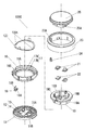
- FIG. 2 is an exploded perspective view of the input device 3000
- FIG. 3 is an exploded perspective view of a rotary operation unit 1000 of the input device 3000. .
- the input device 3000 includes a rotation operation unit 1000 and a touch panel unit 2000 on which the rotation operation unit 1000 is mounted.
- the touch panel unit 2000 includes a touch panel 31 and a transparent resin cover panel 41 stacked on the upper surface of the touch panel 31.
- the rotation operation unit 1000 includes a lower case 11, and the lower surface of the lower case 11 is fitted in the cover panel 41.
- the movable electrode 18 rotates according to the rotation operation of the rotation operation knob 23, and contacts or separates from the fixed electrode 13.
- the electrical state between the fixed electrode 13 and the sensor electrode 32 of the touch panel unit 2000 is changed by the contact or separation between the movable electrode 18 and the fixed electrode 13.
- the rotation operation of the rotation operation unit 1000 can be detected by detecting a change in capacitance generated between the fixed electrode 13 and the sensor electrode 32.
- the input device 3000 includes the sensor electrode 32 that is the first electrode, the fixed electrode 13 that is the second electrode, and the movable electrode 18 that is the third electrode.
- the fixed electrode 13 is spaced apart from the sensor electrode 32.
- the movable electrode 18 is provided to be separated from the sensor electrode 32 and to be rotatable with respect to the fixed electrode 13. When the movable electrode 18 contacts or separates from the fixed electrode 13, the electrical state between the sensor electrode 32 and the fixed electrode 13 changes. A rotation operation can be detected by this electrical change.
- FIG. 4 is a top view of the lower case 11.
- the rotation operation unit 1000 includes a lower case 11, a holder 19, a click spring 120, an elastic body 21, a connection electrode 22, a rotation body 16, a movable electrode 18, a rotation operation knob 23, and a first connection terminal. 24 and a pressing body 25.
- the lower case 11 made of an insulating resin is formed with a concave portion opened upward.
- the lower case 11 is circular when viewed from above, and a groove portion 12 that is annular when viewed from above is provided on the upper surface of the recess. Further, four column portions 11A extending upward and two recess portions 11B are provided at a position inside the groove portion 12.
- the inner bottom surface of the groove portion 12 is formed flat, and a plurality of fixed electrodes 13 made of a thin metal plate insert-molded in the lower case 11 are exposed on the inner bottom surface of the groove portion 12.
- the plurality of fixed electrodes 13 are arranged radially on the inner bottom surface of the groove portion 12, and the adjacent fixed electrodes 13 are electrically insulated from each other by separating the resin surface 14.
- notches are provided at both ends of the portion located on the outer peripheral side of the groove 12. Therefore, on the resin surface 14, the width of the portion located on the outer peripheral side of the groove portion 12 is wider than the width of the portion located on the inner peripheral side of the groove portion 12.
- the insulating resin holder 19 is formed in a circular shape when viewed from above.
- the holder 19 includes a cylindrical portion 19A having a bottom surface, and a flange portion 19B that protrudes in an annular shape from the upper portion of the cylindrical portion 19A in the outer diameter direction.
- a click spring 120 made of an elastic metal and having an annular shape when viewed from above is fixed by caulking to the lower surface of the flange portion 19B.
- the click spring 120 is provided with a protruding portion 120 that protrudes downward in an arc shape.
- a caulking hole 19 ⁇ / b> D is provided on the bottom surface of the holder 19.
- the holder 19 is fixed to the lower case 11 by inserting the column portion 11A of the lower case 11 into the crimping hole 19D and crimping the tip of the column portion 11A.
- a button mounting portion 19 ⁇ / b> C penetrating in a cross shape is formed on the bottom surface of the holder 19.
- the elastic body 21 made of rubber has a truncated cone shape and is open downward.
- the connection electrode 22 is bent in a U shape.
- the lower surface of the connection electrode 22 and the lower surface of the elastic body 21 are accommodated in the recess 11 ⁇ / b> B of the lower case 11.
- the elastic body 21 and the connection electrode 22 form a push button part in the button mounting part 19C.
- the rotating body 16 made of insulating resin is provided with a central hole 16A and is formed in an annular shape when viewed from above.
- the cylindrical portion 19A of the holder 19 is inserted into the central hole 16A. Therefore, the rotating body 16 is fixed to the holder 19 so as to be rotatable.
- an uneven portion 17 formed in an uneven shape is provided over the entire periphery.
- convex portions 17A protruding upward and concave portions 17B recessed downward are alternately formed.
- the protrusion 120A of the click spring 120 is in elastic contact with the upper surface of the concavo-convex portion 17, so that the click moderation is obtained according to a predetermined rotation angle when the rotating body 16 is rotated. That is, the click mechanism that can obtain the click mode according to the predetermined rotation angle when the rotation operation knob 23 is rotated by the uneven portion 17 and the click spring 120 is formed.
- the movable electrode 18 is formed by bending a thin elastic metal into an L shape.
- a contact 18A is formed on one side of the L-shape, and the other side constitutes a fixed portion 18B protruding upward with a predetermined width.
- the movable electrode 18 is fixed to the lower surface of the outer peripheral portion of the rotating body 16 by press-fitting the fixing portion 18 ⁇ / b> B into the insertion portion 16 ⁇ / b> B provided in the rotating body 16.
- the contact 18 ⁇ / b> A of the movable electrode 18 is in elastic contact with a predetermined position on the inner bottom surface of the groove 12 of the lower case 11.
- FIG. 4 schematically shows the arrangement position of the contact 18 ⁇ / b> A of the movable electrode 18.
- the contact 18A is in contact with the inner bottom surface of the groove portion 12 at the position indicated by ⁇ .
- the contact 18 ⁇ / b> A slides on the concentric track T ⁇ b> 1 according to the rotation operation of the rotating body 16.
- the movable electrode 18 contacts and separates from the fixed electrode 13 located on the track T1 by the rotating operation of the rotating body 16. Therefore, the movable electrode 18 is in a state where it is not in contact with any of the fixed electrodes 13 or a state of being in contact with any of the fixed electrodes 13 according to the rotational angle position of the rotating body 16.
- the rotator 16 has the concavo-convex portion 17, and the protrusion 120 ⁇ / b> A of the click spring 120 is in elastic contact with the upper surface of the concavo-convex portion 17.
- the protrusion 120 ⁇ / b> A of the click spring 120 is configured to be positioned in the recess 17 ⁇ / b> B of the uneven portion 17.
- the protrusion 120 ⁇ / b> A is configured to be positioned on the protrusion 17 ⁇ / b> A of the uneven portion 17.
- the rotation operation unit 1000 in a non-operation state in which a predetermined rotation torque is not applied to the rotating body 16, the protrusion 120A is positioned in the recess 17B, and the rotation angle position of the rotating body 16 is stable. . Then, in synchronization with the click moderation in the rotating operation of the rotating body 16, the contact 18 ⁇ / b> A and the fixed electrode 13 are brought into and out of contact with each other.
- the rotation operation knob 23 having an annular shape when viewed from above is fixed so as to be fitted around the rotation body 16 so as to cover the outer periphery of the rotation body 16 and to be rotated around the rotation body 16.
- the rotation operation knob 23 is made of metal, and an insertion groove 23A is provided on the inner peripheral side wall.
- the thin metal first connection terminal 24 is bent in a U shape and has a spring property.
- the first connection terminal 24 is press-fitted and fixed in the insertion groove 23A.
- the first connection terminal 24 is in elastic contact with the fixed portion 18 ⁇ / b> B of the movable electrode 18, and electrically connects the movable electrode 18 and the rotation operation knob 23.
- the rotation operation knob 23 is made of a metal such as aluminum. It should be noted that appearance decoration such as alumite treatment may be applied to a portion touched by an operator's finger, which will be described later, that is, an outer peripheral portion of the rotary operation knob 23. Further, an insulator such as an insulating resin may be formed in a film shape on the outer peripheral portion of the rotary operation knob 23. That is, the outer peripheral portion of the rotary operation knob 23 may be covered with an insulator having a thickness of about 5 to 50 ⁇ m.
- the metal pressing body 25 is circular when viewed from above.
- the lower part of the pressing body 25 is fixed in the holder 19 so as to be movable up and down.
- the upper surface of the pressing body 25 has a mortar shape that is slightly concavely curved, and a design (not shown) is formed.
- the pressing body 25 has a pressing portion 25 ⁇ / b> A protruding downward, and the lower surface of the pressing portion 25 ⁇ / b> A is in contact with the upper surface of the elastic body 21.
- the pressing body 25 is made of a metal such as aluminum. It should be noted that appearance decoration such as alumite treatment may be applied to a portion touched by an operator's finger described later, that is, the upper surface of the pressing body 25. Further, an insulator such as an insulating resin may be formed in a film shape on the upper surface of the pressing body 25. That is, the upper surface of the pressing body 25 may be covered with an insulator having a thickness of about 5 to 50 ⁇ m.
- the rotation operation unit 1000 is configured as described above, and the fixed electrode 13 of the rotation operation unit 1000 faces the upper surface of the touch panel 31 of the touch panel unit 2000.
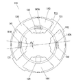
- FIG. 5 is a top view showing an arrangement pattern of the sensor electrodes 32 of the touch panel 31.
- the touch panel unit 2000 includes the touch panel 31 and the transparent resin cover panel 41 stacked on the upper surface of the touch panel 31.
- the touch panel 31 includes a film-shaped first base 31A made of an insulating resin having light permeability, and titanium oxide indium tin ( And a plurality of sensor electrodes 32 and 33 formed transparently with ITO or the like.
- the sensor electrodes 32 and 33 are each formed in a predetermined pattern.
- the touch panel 31 detects a change in capacitance formed between a conductor in contact with or close to the upper surface of the touch panel 31 and the sensor electrodes 32 and 33, and detects a planar position of the conductor. That is, the touch panel 31 is a capacitive type.
- the sensor electrodes 32 and 33 are not necessarily transparent, and may be formed of a metal thin film or the like, for example, by vapor deposition.
- a plurality of sensor electrodes 32 and 33 are formed at positions where the rotation operation unit 1000 is mounted on the touch panel 31.
- Each of the sensor electrodes 32 has substantially the same shape as the fixed electrode 13 in a top view.
- Each of the sensor electrodes 32 is formed at a position facing one of the fixed electrodes 13.
- Each of the sensor electrodes 33 has substantially the same shape as the lower surface of the connection electrode 22 in a top view.
- Each sensor electrode 33 is formed at a position facing one lower surface of the connection electrode 22.
- the sensor electrodes 32 and 33 are connected to lead wires (not shown), respectively, and are connected to a predetermined electronic circuit (not shown).
- the sensor electrodes 32 and 33 may be composed of at least one transmission electrode and at least one reception electrode.
- lattice form is distribute
- the touch panel 31 receives a touch operation with an operator's finger or the like.
- the input device 3000 preferably uses the touch panel 31 in which the sensor electrodes 32 and 33 are configured in the above-described arrangement pattern, but sensor electrodes (transparent electrodes) arranged in a grid pattern are formed on the entire touch panel.
- sensor electrodes transparent electrodes
- a touch panel having a general arrangement pattern may be used.
- the touch panel 31 may be a surface type or a projection type as long as it is a capacitance type. Furthermore, either the self-capacitance method or the mutual capacitance method may be used.
- each of the sensor electrodes 32 and 33 may be composed of at least one transmission electrode and at least one reception electrode.
- FIG. 6 is an enlarged view of a main part showing the relationship between the lower case 11 and the contact 18 ⁇ / b> A of the movable electrode 18.
- 7A to 7C are diagrams for explaining the contact and separation between the movable electrode 18 and the fixed electrode 13.
- 8A to 8C are views for explaining the positional relationship between the protrusion 120A of the click spring 120 and the uneven portion 17 of the rotating body 16 in FIGS. 7A to 7C, respectively.
- a part of the fixed electrode 13 in FIG. 6 is shown as the fixed electrodes 13A and 13B, and a part of the resin surface 14 is shown as the resin surfaces 14A and 14B.
- a part of the fixed electrode 13 in FIGS. 7A to 7C is shown as fixed electrodes 13A and 13B, and the sensor electrodes 32 respectively facing the fixed electrodes 13A and 13B are shown as sensor electrodes 32A and 32B.
- the ⁇ shown in FIG. 6 schematically shows the arrangement position of the contact 18A of the movable electrode 18 as in FIG.
- the contact 18A is in contact with the inner bottom surface of the groove portion 12 at the position indicated by ⁇ .
- the contact 18 ⁇ / b> A slides on the concentric track T ⁇ b> 1 according to the rotation operation of the rotating body 16.
- the protrusion 120A of the click spring 120 is located in the recess 17B of the rotating body 16, and therefore the rotation angle position of the rotation operation knob 23 is stable.
- the contact 18A is in contact with the resin surface 14 (resin surface 14A). That is, the movable electrode 18 is not in contact with any fixed electrode 13.
- the operator's fingers are electrically connected to the movable electrode 18 via the rotary operation knob 23 and the first connection terminal 24. Then, when the operator rotates the rotary operation knob 23 from this state, the rotating body 16 connected to the rotary operation knob 23 is provided. Then, the contact 18A moves on the groove 12 along the track T1, and as shown in FIG. 7B, the contact 18A and the fixed electrode 13 (fixed electrode 13A) come into contact with each other. Even during this movement, the electrical connection between the operator's fingers and the movable electrode 18 is maintained.
- the fixed electrode 13A is electrically connected to the operator's finger through the movable electrode 18, and the electrostatic capacitance generated between the fixed electrode 13A and the sensor electrode 32A changes. Then, the position of the movable electrode 18 is detected by detecting the change in the capacitance by an electronic circuit (not shown).
- the protrusion 120A of the click spring 120 is located on the protrusion 17A of the uneven portion 17 of the rotating body 16 as shown in FIG. 8B. That is, the rotation angle position of the rotation operation knob 23 is not restricted.
- the contact 18A further moves along the track T1 along the track T1 with a click feeling, as shown in FIG. 7C.
- the movable electrode 18 and the resin surface 14 are in contact with each other. That is, the transition is made again to the state in which the movable electrode 18 is not in contact with any fixed electrode 13.
- the contact 18A of the movable electrode 18 slides on the track T1, and according to the rotation angle position, the contact 18A and the fixed electrode 13 (fixed) Electrodes 13A, 13B) are in contact. Then, a change occurs in the capacitance between the fixed electrode 13 to which the contact 18A is connected and the sensor electrode 32, and the change in the capacitance is detected by an electronic circuit (not shown), whereby the movable electrode 18 positions are detected.
- the touch panel 31 detects the movement of the movable electrode 18 by the rotation operation, and the rotation operation according to the rotation direction and the rotation movement amount is performed.
- one fixed electrode 13 (13A) faces one sensor electrode 32 (32A) on a one-to-one basis, but this is not always necessary.
- one fixed electrode 13 (13A) may be opposed so as to straddle two adjacent sensor electrodes 32 (32A, 32B).
- a change in the capacitance generated in each is detected by an electronic circuit (not shown). Then, the electronic circuit can detect the position of the fixed electrode 13 to which the contact 18A is connected by performing a process of comparing changes in capacitance between the two, that is, a signal weighting process.
- the above-described operator's fingers and the movable electrode 18 may be electrically connected in an AC component in addition to being electrically connected so that the DC component can be conducted. That is, even if the outer peripheral portion of the rotary operation knob 23 is covered with a film-like insulator such as anodized or insulating resin, the operator's fingers and the rotary operation knob 23 are sufficiently coupled with each other through the insulator. It is possible to detect the rotation operation described above by being electrically connected.
- the rotation operation knob 23 is formed by conductive plating on the resin molded body and its predetermined surface position. You may comprise with the formed electroconductive part.
- the rotary operation knob 23 may be formed by insert molding a thin metal plate processed into a predetermined shape. In this case, the rotary operation knob 23 may be configured so that the operator's fingers and the movable electrode 18 can be electrically connected via a thin metal plate.
- the movable electrode 18 is not in contact with the fixed electrode 13 when the input device 3000 is not being operated to rotate. For this reason, the touch panel 31 can easily detect the position of the movable electrode 18. That is, the rotation operation is detected stably. The reason will be described in detail below.
- the capacitive touch panel the absolute value of the capacitance fluctuates with time even in a non-operation state due to factors such as temperature change. Therefore, in the capacitive touch panel device, a reference value that changes in accordance with the time variation of the capacitance is set. By performing calibration in this way and determining the amount of change in capacitance from a predetermined reference value, the influence due to time variation of the capacitance is suppressed.
- the above-mentioned reference value is determined by an electronic circuit or the like mounted on the touch panel device, and is preferably constantly updated in order to suppress the influence due to temperature fluctuation.
- Such a reference value is set based on, for example, the absolute value of the capacitance measured when the touch panel device is turned on. After the power is turned on, the reference value is based on the absolute value of the capacitance measured in a state where an operating body such as a finger or a conductor is not in contact with or close to the upper surface of the touch panel every predetermined time. Is set. Then, the reference value is stored in the memory in the electronic circuit, and is updated from the old reference value to the new reference value.
- the capacitance When the capacitance is measured for calibration with foreign objects such as fingers or conductors in contact with or close to the top surface of the touch panel after the power is turned on, the adjacent or contacted foreign objects For example, the capacitance value may deviate greatly from the normal value. In that case, the measured capacitance value deviates from the predetermined setting range. Therefore, the measured capacitance value is controlled so as to be normally calibrated by re-measurement or the like without being set as a reference value.
- a general capacitive touch panel device is designed on the assumption that in a non-operating state, a conductive operation body such as a finger and other foreign objects are not close to the upper surface of the touch panel. Therefore, in a general capacitive touch panel device, when an operation body such as a finger or a foreign object such as a conductor is in contact with or close to the upper surface of the touch panel, The absolute value of the capacitance including foreign objects such as the operation body and the conductor is set as the reference value.
- the rotation operation unit 1000 is always placed on the upper surface of the touch panel unit 2000. Therefore, even if the above-described reference value is set in a state where the rotation operation unit 1000 is always close to the upper surface of the touch panel 31, the electrical influence by the rotation operation unit 1000 is suppressed and calibration of the touch panel 31 is performed correctly. It must be done.
- the input device 3000 is configured such that the movable electrode 18 is not in contact with any fixed electrode 13 in a non-operating state. This will be described in detail below.
- the movable electrode 18 is in contact with the fixed electrode 13A in a non-operating state.
- the electrostatic capacitance between the fixed electrode 13A and the sensor electrode 32A is affected by the movable electrode 18 and the rotary operation knob 23, and is opposed to the other fixed electrode 13 that is not in contact with the movable electrode 18.
- the capacitance between the sensor electrode 32 and the sensor electrode 32 is larger.
- the sensitivity of the sensor electrode 32A is lower than the sensitivity of the other sensor electrodes 32, the sensitivity becomes nonuniform, and it is difficult to stably detect the rotation operation.
- the input device 3000 is configured such that the movable electrode 18 is not in contact with any fixed electrode 13 in a non-operating state. Therefore, all sensor electrodes 32 facing the fixed electrode 13 can be calibrated under the same conditions in which no fixed electrode 13 is in contact with the movable electrode 18. That is, the calibration can be performed in a state in which the movable electrode 18 and the rotary operation knob 23 are less likely to be electrically affected by the sensor electrode 32. Therefore, it is possible to stably detect the rotation operation without lowering the sensitivity of the sensor electrode 32 and suppressing variations in sensitivity.
- the operation of the input device 3000 by pressing operation will be described.
- the elastic body 21 is buckled and deformed with moderation, and the pressing portion 25A of the pressing body 25 comes into contact with the upper surface of the upper portion of the connection electrode 22. .
- the operator's fingers and the connection electrode 22 are electrically connected via the pressing body 25.
- the electrostatic capacitance between the connection electrode 22 and the sensor electrode 33 is increased, and the pressing operation is detected by detecting a change in the electrostatic capacitance by an electronic circuit (not shown).
- the pressing operation is released, the contact between the pressing portion 25A and the connection electrode 22 is released, and the elastic body 21 returns to its original shape.
- the operator's finger and the connection electrode 22 may be electrically connected in the AC component in addition to being electrically connected so that the DC component can be conducted. That is, even if the upper surface of the pressing body 25 is covered with a film-like insulator such as anodized or insulating resin, the operator's fingers and the pressing body 25 are electrically connected by sufficient capacitive coupling via the insulator. By being connected, the above-described pressing operation can be detected.
- the resin molded body is pressed by a conductive portion formed by conductive plating at a predetermined surface position.
- the body 25 may be configured.
- the pressing body 25 may be formed by insert molding a thin metal plate processed into a predetermined shape. In this case, the pressing body 25 may be configured so that the operator's fingers and the connection electrode 22 can be electrically connected via a thin metal plate.
- the lower case 11 may be formed of a resin material having optical transparency such as polycarbonate, and the fixed electrode 13 may be formed of a transparent electrode such as ITO.
- the lower case 11 is a second base material having optical transparency that holds the fixed electrode 13. If the holder 19, the rotating body 16, the rotating operation knob 23, and the pressing body 25 are formed of a resin material having light permeability such as polycarbonate, the rotating operation unit 1000 is irradiated by light irradiated from below the lower case 11. The whole can be illuminated.
- the rotation operation is detected using the capacitance generated between the fixed electrode 13 and the sensor electrode 32.
- an electrical change may be detected by a configuration other than this.
- the rotation operation may be detected by detecting a change in impedance such as inductance generated when the operator's finger touches the rotation operation knob 23.
- a change in impedance such as inductance generated when the operator's finger touches the rotation operation knob 23.
- an electrical change generated between the connection electrode 22 and the sensor electrode 33 may be detected, and the method is not limited to the detection of the change in capacitance. This also applies to Embodiments 2 to 4 described below.
- the input device 3000 includes a rotation operation unit 1000 disposed on the touch panel 31, a sensor electrode 32 that is paired with the fixed electrode 13, and a sensor electrode 33 that is paired with the connection electrode 22.
- a rotation operation unit 1000 disposed on the touch panel 31
- a sensor electrode 32 that is paired with the fixed electrode 13
- a sensor electrode 33 that is paired with the connection electrode 22.
- the sensor electrode does not necessarily need to be transparent.
- the input device may be configured by arranging the rotation operation unit 1000 on a wiring board such as a printed board having a plurality of fixed electrodes exposed in a predetermined pattern on a plate-like base material such as an epoxy resin. Good.
- FIG. 9 is an exploded perspective view of the input device 3001.
- the input device 3001 includes a rotation operation unit 1001 and a touch panel unit 2001 on which the rotation operation unit 1001 is mounted.
- symbol is attached
- FIG. 10
- FIG. 10 is an exploded perspective view of the rotation operation unit 1001
- FIG. 11 is a diagram illustrating a relationship between the contact pattern 51 ⁇ / b> A of the wiring board 51 of the rotation operation unit 1001 and the contacts 53 ⁇ / b> A and 54 ⁇ / b> A of the fixed electrodes 53 and 54.
- the rotation operation unit 1001 is similar to the rotation operation unit 1000 in the first embodiment.
- the lower case 11, the rotation body 16, the click spring 120, the holder 19, the connection electrode 22, the elastic body 21, 1 has a connection terminal 24, a rotary operation knob 23, and a pressing body 25.
- These components are the same as those of the rotation operation unit 1000 unless otherwise specified.
- the rotation operation unit 1001 includes a second connection terminal 58, fixed electrodes 53 and 54, and a wiring board 51 instead of the movable electrode 18 and the fixed electrode 13 in the rotation operation unit 1000.
- the wiring board 51 rotates according to the rotation operation of the rotation operation knob 23, and the contact pattern 51 ⁇ / b> A on the lower surface of the wiring board 51 contacts and separates from the fixed electrodes 53 and 54.
- the second connection terminal 58 is fixed to the lower surface of the outer peripheral portion of the rotating body 16 instead of the movable electrode 18. Further, a wiring substrate 51 formed in an annular plate shape is fixed to the lower surface of the outer peripheral portion of the rotating body 16. Therefore, the wiring board 51 is rotated with the rotating body 16.
- the second connection terminal 58 is formed by bending a thin plate elastic metal into an L shape.
- a contact 58A is formed at the tip of one side of the L-shape, and the other side constitutes a fixed portion 58B protruding upward with a predetermined width.
- the second connecting terminal 58 is fixed to the lower surface of the outer peripheral portion of the rotating body 16 by press-fitting the fixing portion 58 ⁇ / b> B into the insertion portion 16 ⁇ / b> B provided in the rotating body 16.
- the first connection terminal 24 is elastically contacted with the fixing portion 58B of the second connection terminal 58, whereby the second connection terminal 58 and the rotary operation knob 23 are electrically connected.
- a contact pattern 51 ⁇ / b> A formed in a predetermined pattern is formed on the lower surface of the wiring board 51.
- a connection land 51 ⁇ / b> B is provided on the upper surface of the wiring substrate 51.
- the connection land 51B and the contact pattern 51A are electrically connected.
- the contact 58A of the second connection terminal 58 is elastically contacted with the connection land 51B, the contact pattern 51A is electrically connected to the rotation operation knob 23 via the second connection terminal 58 and the first connection terminal 24.
- region other than the contact pattern 51A comprises the insulating surface 51C in the lower surface of the wiring board 51.
- the lower case 11 is provided with the two fixed electrodes 53 and 54 instead of the fixed electrode 13.
- the fixed electrodes 53 and 54 are made of a thin metal plate and are formed in a fan shape when viewed from above, and have an area larger than that of each fixed electrode 13 when viewed from above.
- the fixed electrodes 53 and 54 are respectively provided with contacts 53A and 54A extending upward.
- the contacts 53 ⁇ / b> A and 54 ⁇ / b> A are configured to come in contact with and separate from the contact pattern 51 ⁇ / b> A of the wiring board 51 in accordance with the rotation operation of the rotation operation knob 23.
- the contact 53A schematically indicates the arrangement position of the contact 53A, and the contact 53A is in contact with the lower surface of the wiring board 51 at the position of the mark.
- the contact 53A slides on the concentric track T11 in accordance with the rotating operation of the rotating body 16.
- the x mark schematically shows the arrangement position of the contact 54A, and the contact 54A is in contact with the lower surface of the wiring board 51 at the position of the x mark.
- the contact 54A slides on the concentric track T12 in accordance with the rotating operation of the rotating body 16.
- FIG. 12 is a top view showing an arrangement pattern of the sensor electrodes 33, 62A, 62B of the touch panel 61.
- FIG. 12 is a top view showing an arrangement pattern of the sensor electrodes 33, 62A, 62B of the touch panel 61.
- sensor electrodes 62A and 62B are arranged on the upper surface of the first base 31A in place of the sensor electrode 32.
- the sensor electrode 62 ⁇ / b> A has substantially the same shape as the fixed electrode 53 in a top view, and is disposed at a position facing the fixed electrode 53.
- the sensor electrode 62 ⁇ / b> B has substantially the same shape as the fixed electrode 54 in a top view, and is disposed at a position facing the fixed electrode 54.
- lead wires (not shown) are connected to the sensor electrodes 62A and 62B, respectively, and are connected to a predetermined electronic circuit (not shown).
- the sensor electrodes 62A and 62B are formed of ITO or the like so as to be transparent.
- the sensor electrodes 62A and 62B are not necessarily transparent, and may be formed of a metal thin film formed by vapor deposition or the like, for example. Furthermore, each of the sensor electrodes 62A and 62B may be composed of at least one transmission electrode and at least one reception electrode.
- the contact 53 ⁇ / b> A contacts and separates from the contact pattern 51 ⁇ / b> A of the wiring board 51 by rotating the rotation operation knob 23.
- the capacitance between the fixed electrode 53 and the sensor electrode 62A changes due to the contact and separation.
- An electronic circuit (not shown) detects this change in capacitance as an A signal.
- the contact 54 ⁇ / b> A contacts and separates from the contact pattern 51 ⁇ / b> A by the rotation operation of the rotation operation knob 23.
- the capacitance between the fixed electrode 54 and the sensor electrode 62B changes due to the contact and separation.
- the above-described electronic circuit detects this change in capacitance as a B signal.
- the input device 3001 detects a change in capacitance generated between the fixed electrodes 53 and 54 of the rotation operation unit 1001 and the sensor electrodes 62A and 62B of the touch panel unit 2001, thereby Detect rotation operation.
- the input device 3001 includes the sensor electrodes 62A and 62B that are the first electrodes, the fixed electrodes 53 and 54 that are the second electrodes, and the contact pattern 51A that is the third electrode.
- the fixed electrodes 53 and 54 are spaced apart from the sensor electrodes 62A and 62B.
- the contact pattern 51A is provided so as to be separated from the sensor electrodes 62A and 62B and to be rotatable with respect to the fixed electrodes 53 and 54.
- the electrical state between the sensor electrodes 62A and 62B and the fixed electrodes 53 and 54 changes when the contact pattern 51A is electrically contacted with or separated from the fixed electrodes 53 and 54. A rotation operation can be detected by this electrical change.
- the contact pattern 51A formed on the lower surface of the wiring board 51 is a contact pattern for an incremental encoder. Since the contact pattern 51A has such a shape, there is a predetermined phase difference between the contact 53A and the contact pattern 51A due to the rotation operation of the rotation operation knob 23 and the contact 54A and the contact pattern 51A. Occurs.
- the A signal and B signal described above are output signals of the increment method, and the electronic circuit processes the A signal and the B signal so that the rotation operation according to the rotation direction and the rotation movement amount of the rotation operation knob 23 is performed. Can be detected.
- the detection sensitivity is increased.
- the rotation operation unit 1001 is in contact with the insulating surface 51C in the non-operation state. That is, the contact pattern 51A and the fixed electrodes 53 and 54 are not in contact with each other in a non-operation state.
- the sensor electrodes 62A and 62B facing the fixed electrodes 53 and 54 can be calibrated under the same condition that both the fixed electrodes 53 and 54 are not in contact with the contact pattern 51A. That is, calibration can be performed in a state in which the contact pattern 51A of the wiring board 51 and the rotation operation knob 23 are less likely to be electrically affected by the sensor electrodes 62A and 62B.
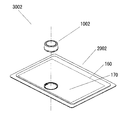
- FIG. 13 is an exploded perspective view of the input device 3002.
- the input device 3002 includes a rotation operation unit 1002 and a touch panel unit 2002 on which the rotation operation unit 1002 is mounted.
- the touch panel unit 2002 includes a touch panel 160 and a transparent resin cover panel 170 laminated on the upper surface of the touch panel 160.
- FIGS. 14 is an exploded perspective view of the rotation operation unit 1002
- FIG. 15 is a perspective view of the lower case 111 of the rotation operation unit 1002
- FIG. 16 is an exploded perspective view of the lower case 111
- FIG. 17 is a bottom view of the lower case 111
- FIG. 8 is a diagram showing the relationship between the contact pattern 115A of the wiring board 115 of the rotation operation unit 1002 and the contacts 141A to 143A.
- the rotation operation unit 1002 includes a lower case 111, a first switch electrode 112, a second switch electrode 113, an elastic body 114, a wiring board 115, a rotation body 116, and a rotation operation knob. 118, a holder 119, a click spring 120, and a pressing body 121.
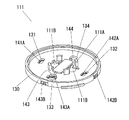
- the lower case 111 includes a resin portion 130, a fixed electrode 141, a fixed electrode 142, a fixed electrode 143, and a fixed electrode 144.
- the resin portion 130 made of insulating resin is formed with a concave portion opened upward.
- the resin portion 130 has a circular shape when viewed from above, and fixed electrodes 141 to 144 are fixed to the lower surface of the resin portion 130.
- In the center of the concave portion of the resin portion 130 four column portions 111A extending upward and two hollow portions 111B are provided. Further, the resin portion 130 is provided with four holes 131 to 134 on the upper surface of the concave portion outside the column portion 111A.
- the fixed electrodes 141 to 144 have a fan-like thin-plate metallic property and have substantially the same shape in the top view.
- the fixed electrodes 141 to 144 have U-shaped hooking portions 141B to 144B protruding upward.
- the fixed electrodes 141 to 144 are each provided with a protruding portion 145 protruding upward with a predetermined width.
- the fixed electrodes 141 to 144 are fixed to the lower surface of the resin portion 130 by the latching portions 141B to 144B and the protruding portion 145.
- the latching portions 141B to 144B are engaged with engaging portions 146 provided on the outer periphery of the resin portion 130, respectively, and the protruding portions 145 are engaging holes (not shown) provided on the lower surface of the resin portion 130. )).
- the fixed electrodes 141 to 144 are exposed from the lower surface of the lower case 111.
- the fixed electrodes 141 to 143 are provided with contacts 141A to 143A protruding upward, respectively.
- the contacts 141A to 143A protrude above the recesses of the resin part 130 through the holes 131 to 133 of the resin part 130.
- the contacts 141A to 143A are in contact with the lower surface of the wiring board 115 shown in FIGS. A part of the fixed electrode 144 is exposed from the hole 134 of the resin portion 130.
- the first switch electrode 112 is a thin plate metal formed in a predetermined shape.
- the first switch electrode 112 has a contact 112A bent downward and two contact portions 112B that are circular in top view and slightly protrude upward.
- the first switch electrode 112 is mounted on the upper surface of the recess of the lower case 111.
- the contact 112A is in contact with the contact 143A of the fixed electrode 143 exposed from the hole 133.
- the two contact portions 112B are accommodated in the two recess portions 111B, respectively.
- the second switch electrode 113 is a thin metal plate formed in a predetermined shape.
- the second switch electrode 113 has a contactor 113A bent downward and two contact portions 113B that are circular in top view and slightly protrude downward.
- the second switch electrode 113 is also mounted on the upper surface of the recess of the lower case 111.
- the contactor 113A is in contact with the fixed electrode 144 exposed from the hole 134.
- the two contact portions 113B are accommodated in the two recess portions 111B, respectively.
- the contact part 112B of the first switch electrode 112 and the contact part 113B of the second switch electrode 113 are opposed to each other with a predetermined interval. That is, the first switch electrode 112 and the second switch electrode 113 are not in contact with each other.
- the rubber elastic body 114 is formed in a truncated cone shape having an opening at the bottom.
- the bottom of the elastic body 114 is accommodated in the recess 111B of the lower case 111.
- the elastic body 114, the first switch electrode 112, and the second switch electrode 113 form a push button portion. That is, when the operator presses the pressing body 121, the pressing portion 121A presses the elastic body 114, and the elastic body 114 is buckled and deformed with moderation. Thereby, the contact part 112B of the 1st switch electrode 112 and the contact part 113B of the 2nd switch electrode 113 contact.
- the fixed electrode 143 and the fixed electrode 144 are electrically connected via the first switch electrode 112 and the second switch electrode 113.
- the holder 119 made of insulating resin is circular when viewed from above, and has a cylindrical portion 119A having a bottom surface and a flange portion 119B protruding in an annular shape from the upper portion of the cylindrical portion 119A in the outer diameter direction.
- a click spring 120 made of an elastic metal and having an annular shape in a top view is fixed by caulking.
- a caulking hole 119D is provided on the bottom surface of the holder 119.
- the holder 119 is fixed to the lower case 111 by inserting the column portion 111A of the lower case 111 into the crimping hole 119D and crimping the tip of the column portion 111A.
- a button mounting portion 119C penetrating in a circular shape slightly smaller than the bottom portion of the elastic body 114 is formed.
- the elastic body 114 is inserted into the button mounting portion 119C and held by the holder 119.
- the rotating body 116 made of insulating resin is provided with a central hole 116A and is formed in an annular shape when viewed from above.
- the cylindrical portion 119A of the holder 119 is inserted into the central hole 116A. Therefore, the rotating body 116 is fixed so as to be rotatable with respect to the holder 119.
- an uneven portion 117 formed in an uneven shape is provided over the entire periphery.
- convex portions 117A protruding upward and concave portions 117B recessed downward are alternately formed.
- the protrusion 120 ⁇ / b> A of the click spring 120 is in elastic contact with the upper surface of the concavo-convex portion 117 of the rotating body 116. Thereby, the operator obtains a click moderation according to a predetermined rotation angle when the rotating body 116 is rotated.
- the relationship between the holder 119, the click spring 120, and the rotating body 116 is the same as the relationship between the holder 19, the click spring 120, and the rotating body 16 in the first embodiment.
- the wiring board 115 is circular when viewed from above, and a contact pattern 115A, which is a conductive region having a predetermined pattern, is formed on the lower surface.
- the region other than the contact pattern 115A constitutes an insulating surface 115C that is an insulating region.
- the wiring board 115 is fixed to the lower surface of the outer peripheral portion of the rotator 116 and rotates with the rotator 116.
- the contacts 141A to 143A are in elastic contact with the lower surface of the wiring board 115.
- FIGS. 17 and 18 schematically shows the arrangement positions of the contacts 141A to 143A, and the contacts 141A to 143A are in contact with the lower surface of the wiring board 115 at the positions of these marks.
- the contact 141 ⁇ / b> A of the fixed electrode 141 and the contact 142 ⁇ / b> A of the fixed electrode 142 slide on the concentric track T ⁇ b> 22 according to the rotation operation of the rotating body 116.
- the contact 141A is arranged at an angular position having a predetermined phase difference ( ⁇ ) with respect to the contact 142A.
- ⁇ predetermined phase difference
- the contact 143A of the fixed electrode 143 slides on the concentric track T21 in accordance with the rotating operation of the rotating body 116.
- the contact pattern 115A is formed over the entire circumference, the contact pattern 115A and the contactor 143A are always in contact with each other regardless of the rotating operation of the rotating body 116.
- the resin-made rotation operation knob 118 has an annular shape when viewed from above, and is fixed to the rotating body 116 and rotates together with the rotating body 116.
- the resin-made pressing body 121 is circular when viewed from above, and includes a pressing portion 121A that protrudes downward in a convex shape.
- the pressing body 121 is fixed in the holder 119 so as to be movable up and down.
- the lower surface of the pressing portion 121 ⁇ / b> A of the pressing body 121 is in contact with the upper surface of the elastic body 114.
- the rotation operation unit 1002 is configured, and the fixed electrodes 141 to 144 of the rotation operation unit 1002 face the upper surface of the touch panel 160 of the touch panel unit 2002.
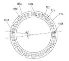
- FIG. 19 is a top view illustrating an arrangement pattern of the sensor electrodes 161, 162, and 164 of the touch panel 160 in the touch panel unit 2002.
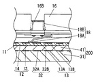
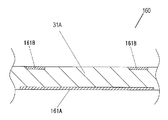
- 19 is a sectional view taken along line 20-20 in FIG.
- the touch panel 160 includes a first base material 31 ⁇ / b> A, sensor electrodes 161, 162, and 164, and a ground electrode 163.
- the sensor electrodes 161, 162, and 164 are formed at positions facing the lower surfaces of the fixed electrodes 141, 142, and 144, respectively.
- the ground electrode 163 is formed at a position facing the lower surface of the fixed electrode 143.
- lead wires (not shown) are connected to the sensor electrodes 161, 162, and 164, respectively, and are connected to a predetermined electronic circuit (not shown).
- the ground electrode 163 is connected to a lead wire (not shown) and is connected to the ground potential of the electronic circuit.
- the touch panel 160 is a capacitance that detects changes in capacitance formed between the conductors (fixed electrodes 141, 142, 144) in contact with or close to the upper surface thereof and the sensor electrodes 161, 162, 164, respectively.
- This is a touch panel. That is, the touch panel 160 only needs to be able to detect a change in capacitance, and thus may be either a self-capacitance method or a mutual capacitance method. Further, it may be a surface type or a projection type. In the following description, a mutual capacitive touch panel 160 will be described as an example.
- the sensor electrode 161 is composed of a pair of a transmission electrode 161A and a reception electrode 161B.
- the sensor electrode 162 includes a pair of transmission electrodes 162A and a reception electrode 162B
- the sensor electrode 164 includes a pair of transmission electrodes 164A and a reception electrode 164B.
- the receiving electrodes 161B, 162B, and 164B are hatched.
- the reception electrode 161B is disposed on the upper surface (the surface facing the fixed electrode 141) of the first base material 31A, and the transmission electrode 161A is disposed on the lower surface of the first base material 31A.
- the receiving electrodes 162B and 164B are arranged on the upper surface of the first base material 31A, and the transmitting electrodes 162A and 164B are provided on the lower surface of the first base material 31A. Is arranged.
- the ground electrode 163 is distribute
- the transmission electrodes 161A, 162A, and 164A have a fan shape when viewed from above, and are substantially the same shape as those of the fixed electrodes 141 to 144 when viewed from above.
- the outer edges of the receiving electrodes 161B, 162B, and 164B are formed in a fan shape when viewed from above.
- the receiving electrodes 161B, 162B, 164B are annular.
- the outer edges of the receiving electrodes 161B, 162B, and 164B are formed inside the outer edges of the transmitting electrodes 161A, 162A, and 164A.
- the reception electrodes 161B, 162B, and 164B are more susceptible to electromagnetic noise than the transmission electrodes 161A, 162A, and 164A.
- the reception electrodes 161B, 162B, and 164B are smaller than the transmission electrodes 161A, 162A, and 164A. Therefore, in the touch panel 160, the electromagnetic wave noise is shielded by the transmission electrodes 161A, 162A, and 164A.
- the transmission electrodes 161A, 162A, and 164A can protect the reception electrodes 161B, 162B, and 164B that are easily affected by electromagnetic noise. Thereby, the fall of the detection sensitivity of the sensor electrodes 161, 162, and 164 due to electromagnetic noise can be prevented.
- the top view shape of the fixed electrodes 141, 142, 144 may be smaller than the sensor electrodes 161, 162, 164.
- the fixed electrodes 141, 142, 144 may be opposed to only the transmission electrodes 161A, 162A, 164A, which are smaller than the inner edges of the reception electrodes 161B, 162B, 164B.
- the fixed electrodes 141, 142, and 144 and the sensor electrodes 161, 162, and 164 face each other, so that the rotation operation can be detected.
- the top view shape of the fixed electrodes 141, 142, 144 may be larger than the sensor electrodes 161, 162, 164.
- the ground electrode 163 has a fan shape when viewed from above, and is substantially the same shape as the shape when viewed from the top surface of the fixed electrode 143.
- the sensor electrodes 161, 162, 164 and the ground electrode 163 are transparently made of ITO or the like. Further, the sensor electrodes 161, 162, 164 and the ground electrode 163 may be formed of a metal thin film formed by vapor deposition or the like.
- the transmission electrodes 161A, 162A, 164A and the reception electrodes 161B, 162B, 164B are formed on different planes, but may be formed on the same plane.
- Each of the transmission electrodes 161A, 162A, and 164A and the reception electrodes 161B, 162B, and 164B may be electrically independent.
- the transmission electrodes are comb-like in the top view, and comb-like in the top view.
- the receiving electrode may be formed on the same surface.
- the input device 3002 is configured as described above. Next, the operation of the input device 3002 in the rotation operation will be described.
- the fixed electrode 143 faces the ground electrode 163 of the touch panel 160 in close proximity, the fixed electrode 143 and the ground electrode 163 are largely capacitively coupled. In other words, the fixed electrode 143 and the ground electrode 163 are electrically connected in the AC component.
- the contacts 141A and 142A come into contact with and separate from the contact pattern 115A of the wiring board 115. Since the contact 143A is always in contact with the contact pattern 115A, for example, when the contact 141A contacts the contact pattern 115A, the fixed electrode 141 and the fixed electrode 143 are electrically connected. As a result, the fixed electrode 141 is electrically connected to the ground electrode 163, and the electrical state of the fixed electrode 141 changes. Thereby, the electrostatic capacitance between the fixed electrode 141 and the sensor electrode 161 changes.
- the capacitance (capacitive coupling) formed between the transmission electrode 161A and the reception electrode 161B changes due to the change in the electrical state of the fixed electrode 141 arranged in the vicinity of the sensor electrode 161. .
- An electronic circuit (not shown) detects this change in capacitance as an A signal.
- the electrostatic capacitance between the fixed electrode 142 and the sensor electrode 162 changes due to the contact operation of the contact 142A with respect to the contact pattern 115A by the rotation operation. That is, the electrical state of the fixed electrode 142 disposed in the vicinity of the sensor electrode 162 changes. Therefore, the electrostatic capacitance (capacitive coupling) formed between the transmission electrode 162A and the reception electrode 162B changes. Then, the electronic circuit detects this change in capacitance as a B signal.
- the plurality of insulating surfaces 115C formed on the track T22 of the wiring board 115 are arranged at equal angular intervals as shown in FIG. That is, in the track T22, the contact patterns 115A are arranged at equal angular intervals so as to alternate with the insulating surface 115C. Then, the contacts 141A and 142A slide on the track T22. As shown in FIGS. 17 and 18, the contact 141A is arranged at an angular position having a predetermined phase difference ( ⁇ ) with respect to the contact 142A. Thus, a predetermined phase difference is generated between the contact pattern 115A and the contact 141A due to the rotation operation of the rotation operation knob 118, and the contact pattern 115A and the contact 142A.
- the A signal and the B signal are output signals of an increment method having a predetermined phase difference. Then, the electronic circuit processes the A signal and the B signal, so that a rotation operation corresponding to the rotation direction and the rotation movement amount of the rotation operation knob 118 is detected.
- the wiring board 115 is rotated according to the rotation operation of the rotation operation unit 1002.
- the contact 141A of the fixed electrode 141 and the contact 142A of the fixed electrode 142 are brought into contact with and separated from the contact pattern 115A on the lower surface of the wiring board 115 shown in FIG.
- a rotation operation of the rotation operation unit 1002 is detected by detecting a change in electric capacity.
- the input device 3002 includes the sensor electrodes 161 and 162 that are the first electrodes, the fixed electrodes 141 and 142 that are the second electrodes, and the contact pattern 115A that is the third electrode.
- the fixed electrodes 141 and 142 are spaced apart from the sensor electrodes 161 and 162.
- the contact pattern 115 ⁇ / b> A is separated from the sensor electrodes 161 and 162, and is provided to be rotatable with respect to the fixed electrodes 141 and 142.
- the contact pattern 115 ⁇ / b> A contacts or separates from the fixed electrodes 141 and 142, the electrical state between the sensor electrodes 161 and 162 and the fixed electrodes 141 and 142 changes. A rotation operation can be detected by this electrical change.
- the sensor electrode 161 and the sensor electrode 162 are formed in line symmetry so as to have a mirror image relationship. Thereby, the sensitivity variation of the sensor electrode 161 and the sensor electrode 162 can be suppressed. That is, since the variation in the output intensity of the A signal and the B signal can be suppressed, the rotation operation can be detected stably. Further, since the distance between the sensor electrode 161 and the sensor electrode 162 is increased, the electrical influence on each other can be reduced. This also suppresses variations in the output intensity of the A and B signals.
- the rotation operation unit 1002 is in contact with the insulating surface 115C in the non-operation state. That is, in the non-operation state, the fixed electrodes 141 and 142 are not in contact with the contact pattern 115A.
- the sensor electrodes 161 and 162 can be calibrated under the same condition that both the fixed electrodes 141 and 142 are not in contact with the contact pattern 51A. That is, the calibration can be performed in a state in which the contact pattern 115A of the wiring board 115 and the fixed electrode 143 hardly influence the sensor electrodes 161 and 162. As a result, it is possible to stably detect the rotation operation without reducing the sensitivity of the sensor electrodes 161 and 162 and suppressing variations in sensitivity.
- the fixed electrode 143 and the ground electrode 163 are largely capacitively coupled, they are electrically connected in the AC component.
- the elastic body 114 is buckled and deformed with moderation.
- the contact part 112B of the 1st switch electrode 112 and the contact part 113B of the 2nd switch electrode 113 contact, and the fixed electrode 143 and the fixed electrode 144 are electrically connected. Therefore, the fixed electrode 144 is electrically connected to the ground electrode 163 via the second switch electrode 113, the first switch electrode 112, and the fixed electrode 143, and the electrical state of the fixed electrode 144 changes. .
- the capacitance generated between the fixed electrode 144 and the sensor electrode 164 changes.
- the electrical state of the fixed electrode 144 arranged in the vicinity of the sensor electrode 164 changes, and the capacitance (capacitive coupling) formed between the transmission electrode 164A and the reception electrode 164B changes.
- the pressing operation is detected by detecting the change in the capacitance by an electronic circuit (not shown).
- the elastic body 114 returns to its original shape, and the contact between the first switch electrode 112 and the second switch electrode 113 is released.
- the input device 3002 has the ground electrode 163 that is the fourth electrode electrically connected to the contact pattern 115A.
- the ground electrode 163 is electrically connected to the fixed electrode 141 instead of the operator's finger, and the capacitance between the fixed electrode 141 and the sensor electrode 161 changes.
- the ground electrode 163 is electrically connected to the fixed electrode 142 instead of the operator's finger, and the capacitance between the fixed electrode 142 and the sensor electrode 162 changes.
- the rotation operation can be detected even if the rotation operation knob 118 is made of resin and the operator's finger is not electrically connected to the fixed electrode.
- the ground electrode 163 is electrically connected to the fixed electrode 144 instead of the operator's finger, and the capacitance between the fixed electrode 144 and the sensor electrode 164 changes. To do. Accordingly, the pressing operation can be detected even when the pressing body 121 is made of resin and the operator's finger is not electrically connected to the fixed electrode.
- the input device 3002 does not require the electrical connection between the operator's finger and the fixed electrode as described in the first and second embodiments in order to cause the capacitance to change. Therefore, for example, even when an operator wearing thick gloves or the like operates the input device 3002, a rotation operation or a pressing operation can be easily detected. That is, the input device 3002 can stably detect a rotation operation or a pressing operation with respect to a difference in operation status caused by an operator such as the presence or absence of gloves.
- the rotary operation knob 118 and the pressing body 121 are not necessarily made of resin. For example, it may be made of metal like the rotary operation knob 23 and the pressing body 25.
- the rotation operation knob 118 and the fixed electrodes 141 and 142 are not electrically connected. Therefore, for example, even if an operator's fingers or other conductors inadvertently touch the rotary operation knob 118, the capacitance hardly changes. As a result, the input device 3002 can obtain a stable output with less noise from the sensor electrodes 161 and 162.
- the ground electrode 163 is connected to the ground.
- the potential of the ground electrode 163 is not necessarily set to the ground potential.
- the ground electrode 163 may be connected to an arbitrary reference potential.
- the above-described reference potential may be constant or may vary. That is, a voltage different from a predetermined voltage applied to the sensor electrodes 161, 162, 164 (transmitting electrodes 161A, 162A, 164A) may be applied to the ground electrode 163.
- the fixed electrodes 141 to 144 are exposed from the lower surface of the lower case 111.
- the distances between the sensor electrodes 161, 162, 164 and the fixed electrodes 141, 142, 144 are reduced, and the electrical coupling between them is increased.
- the distance between the ground electrode 163 and the fixed electrode 143 is reduced, and the electrical coupling between them is increased.
- the change of electrostatic capacitance becomes large and it can detect rotation operation and a press operation stably.
- the input devices 3001 and 3002 have a plurality of sensor electrodes and fixed electrodes.
- the annular contact pattern which is the third electrode that is in contact with and away from the fixed electrode, changes the electrical state between each of the sensor electrodes and each of the opposed fixed electrodes so that a phase difference occurs between them.
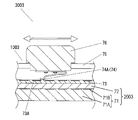
- FIG. 21 is a cross-sectional view of the input device 3003.
- the input device 3003 has a slide operation unit 1003 and a touch panel unit 2003 on which the slide operation unit 1003 is mounted.
- the slide operation unit 1003 includes a lower case 73, a plurality of fixed electrodes 73A, a movable electrode 74, an upper case 75, and a slide operation knob 76. Further, the slide operation unit 1003 has a click mechanism (not shown). As with the rotation operation unit 1000, the click mechanism has the click spring protrusion elastically contacted with the upper surface of the concavo-convex part so that the click moderation can be obtained according to a predetermined movement amount during the slide operation. What is necessary is just to comprise.
- the click mechanism of the slide operation unit 1003 includes an uneven portion fixed to the fixed electrode 73A and a click spring fixed to the slide operation knob 76.
- the concavo-convex portions are linearly arranged in the slide operation direction, and are configured such that the protrusions of the click springs are in elastic contact with the upper surfaces of the concavo-convex portions. Thereby, click moderation is obtained according to a predetermined movement amount at the time of a slide operation.
- the touch panel unit 2003 includes a touch panel 71 and a cover panel 72.
- the touch panel 71 includes a first base 71A and a plurality of sensor electrodes 71B arranged linearly on the upper surface of the first base 71A.
- the sensor electrode 71B is transparently formed of ITO or the like. Note that the sensor electrode 71B is not necessarily transparent, and may be formed of a metal thin film or the like, for example, by vapor deposition. Furthermore, the sensor electrode 71B may be composed of at least one transmission electrode and at least one reception electrode.
- the fixed electrode 73A disposed on the upper surface of the lower case 73 is opposed to one of the sensor electrodes 71B through the lower case 73 and the cover panel 72, respectively.
- the movable electrode 74 is electrically connected to the slide operation knob 76, and when the operator's finger touches the slide operation knob 76, the operator's finger and the movable electrode 74 are electrically connected.
- the input device 3003 can detect the position of the movable electrode 74 by detecting this change in capacitance by an electronic circuit (not shown). Based on this detection, the device on which the input device 3003 is mounted is operated according to the moving direction and moving amount of the slide operation knob 76.
- the input device 3003 detects a slide operation by detecting a change in capacitance generated between the fixed electrode 73A of the slide operation unit 1003 and the sensor electrode 71B of the touch panel unit 2003. That is, the input device 3003 includes a sensor electrode 71B that is a first electrode, a fixed electrode 73A that is a second electrode, and a movable electrode 74 that is a third electrode.
- the fixed electrode 73A is spaced apart from the sensor electrode 71B.
- the movable electrode 74 is separated from the sensor electrode 71B and is slidable with respect to the fixed electrode 73A.
- the electrical state between the sensor electrode 71B and the fixed electrode 73A changes. The slide operation can be detected by this electrical change.
- the slide operation unit 1003 is configured so that the movable electrode 74 and the fixed electrode 73A do not come into contact with each other in the non-operation state by the click mechanism described above. Therefore, all the sensor electrodes 71B can be calibrated under the same condition that the movable electrode 74 is not in contact with any fixed electrode 73A. That is, the calibration can be performed in a state in which the movable electrode 74 and the slide operation knob 76 do not easily affect the sensor electrode 71B. As a result, it is possible to stably detect the slide operation without lowering the sensitivity of the sensor electrode 71B and suppressing variations in sensitivity.
- the input device can detect a predetermined operation stably, it is useful as an input operation unit of various electronic devices.
Landscapes
- Engineering & Computer Science (AREA)
- General Engineering & Computer Science (AREA)
- Theoretical Computer Science (AREA)
- Human Computer Interaction (AREA)
- Physics & Mathematics (AREA)
- General Physics & Mathematics (AREA)
- Switches With Compound Operations (AREA)
- Rotary Switch, Piano Key Switch, And Lever Switch (AREA)
- Switches That Are Operated By Magnetic Or Electric Fields (AREA)
- Slide Switches (AREA)
- Switch Cases, Indication, And Locking (AREA)
Priority Applications (5)
| Application Number | Priority Date | Filing Date | Title |
|---|---|---|---|
| CN201580049167.XA CN106716580B (zh) | 2014-11-10 | 2015-11-05 | 输入装置 |
| US15/516,221 US20170316901A1 (en) | 2014-11-10 | 2015-11-05 | Input device |
| JP2016558874A JP6627085B2 (ja) | 2014-11-10 | 2015-11-05 | 入力装置 |
| EP15859633.8A EP3220402B1 (en) | 2014-11-10 | 2015-11-05 | Input device |
| US16/186,270 US10483057B2 (en) | 2014-11-10 | 2018-11-09 | Input device |
Applications Claiming Priority (4)
| Application Number | Priority Date | Filing Date | Title |
|---|---|---|---|
| JP2014-228083 | 2014-11-10 | ||
| JP2014228083 | 2014-11-10 | ||
| JP2015-168415 | 2015-08-28 | ||
| JP2015168415 | 2015-08-28 |
Related Child Applications (2)
| Application Number | Title | Priority Date | Filing Date |
|---|---|---|---|
| US15/516,221 A-371-Of-International US20170316901A1 (en) | 2014-11-10 | 2015-11-05 | Input device |
| US16/186,270 Continuation US10483057B2 (en) | 2014-11-10 | 2018-11-09 | Input device |
Publications (1)
| Publication Number | Publication Date |
|---|---|
| WO2016075907A1 true WO2016075907A1 (ja) | 2016-05-19 |
Family
ID=55954011
Family Applications (1)
| Application Number | Title | Priority Date | Filing Date |
|---|---|---|---|
| PCT/JP2015/005548 WO2016075907A1 (ja) | 2014-11-10 | 2015-11-05 | 入力装置 |
Country Status (5)
| Country | Link |
|---|---|
| US (2) | US20170316901A1 (zh) |
| EP (1) | EP3220402B1 (zh) |
| JP (1) | JP6627085B2 (zh) |
| CN (1) | CN106716580B (zh) |
| WO (1) | WO2016075907A1 (zh) |
Cited By (13)
| Publication number | Priority date | Publication date | Assignee | Title |
|---|---|---|---|---|
| WO2019098055A1 (ja) * | 2017-11-20 | 2019-05-23 | パナソニックIpマネジメント株式会社 | 入力装置 |
| KR20190098772A (ko) * | 2017-12-28 | 2019-08-23 | 현대자동차주식회사 | 터치 입력장치 및 이를 포함하는 차량 |
| JP2020514875A (ja) * | 2017-01-25 | 2020-05-21 | ベーア−ヘラー サーモコントロール ゲーエムベーハー | 自動車用の操作装置 |
| KR102123575B1 (ko) * | 2019-02-01 | 2020-06-16 | 주식회사 무인트 | 다이얼 노브 |
| WO2020208940A1 (ja) * | 2019-04-10 | 2020-10-15 | パナソニックIpマネジメント株式会社 | プッシュスイッチ、及び照明付きスイッチ装置 |
| WO2020246076A1 (ja) * | 2019-06-04 | 2020-12-10 | パナソニックIpマネジメント株式会社 | 入力装置、入力システム、操作検出方法、プログラム及び非一時的記録媒体 |
| WO2020246077A1 (ja) | 2019-06-07 | 2020-12-10 | パナソニックIpマネジメント株式会社 | 入力装置及び入力システム |
| JPWO2020262380A1 (zh) * | 2019-06-28 | 2020-12-30 | ||
| WO2020262385A1 (ja) | 2019-06-28 | 2020-12-30 | パナソニックIpマネジメント株式会社 | 入力装置 |
| WO2020262390A1 (ja) | 2019-06-28 | 2020-12-30 | パナソニックIpマネジメント株式会社 | 入力装置 |
| JPWO2021193249A1 (zh) * | 2020-03-26 | 2021-09-30 | ||
| JP2023502870A (ja) * | 2020-01-19 | 2023-01-26 | 佛山市▲順▼▲徳▼区美的▲電▼▲熱▼▲電▼器制造有限公司 | ノブ、家電製品、磁気吸着ノブの制御方法、及び磁気吸着操作制御ノブの操作制御を検出するための識別方法 |
| WO2023053682A1 (ja) * | 2021-09-28 | 2023-04-06 | 信越ポリマー株式会社 | 静電容量型入力装置 |
Families Citing this family (25)
| Publication number | Priority date | Publication date | Assignee | Title |
|---|---|---|---|---|
| USD814428S1 (en) | 2016-06-30 | 2018-04-03 | Lutron Electronics Co., Ltd. | Control device |
| USD808912S1 (en) * | 2016-06-03 | 2018-01-30 | Lutron Electronics Co., Inc. | Control device |
| CN106775120B (zh) * | 2017-01-16 | 2021-01-29 | 京东方科技集团股份有限公司 | 一种触控面板及触控显示装置 |
| USD837168S1 (en) | 2017-02-16 | 2019-01-01 | Lutron Electronics Co., Inc. | Control device |
| JP6632786B2 (ja) * | 2017-10-11 | 2020-01-22 | 三菱電機株式会社 | ノブおよび入力装置 |
| CN111164552B (zh) * | 2017-10-11 | 2023-03-21 | 三菱电机株式会社 | 旋钮和输入装置 |
| USD865685S1 (en) * | 2017-11-07 | 2019-11-05 | Ma Lighting Technology Gmbh | Dual encoder button |
| DE112017008192T5 (de) * | 2017-12-14 | 2020-07-30 | Mitsubishi Electric Corporation | Bedienunterstützungseinrichtung, Berührungsfeldeinrichtung und Berührungsfeldeingabesystem |
| DE102018116833A1 (de) | 2018-07-11 | 2020-01-16 | Bcs Automotive Interface Solutions Gmbh | Kapazitives Kraftfahrzeugbediensystem |
| WO2020031501A1 (ja) * | 2018-08-08 | 2020-02-13 | アルプスアルパイン株式会社 | 操作装置および操作部 |
| US10747367B2 (en) * | 2018-09-28 | 2020-08-18 | GM Global Technology Operations LLC | OBDII failure diagnostics techniques for knobs and buttons |
| WO2020079729A1 (ja) * | 2018-10-15 | 2020-04-23 | 三菱電機株式会社 | タッチパネル入力装置、タッチパネル入力方法、及びプログラム |
| CN111372398B (zh) * | 2018-12-25 | 2021-08-31 | 北京小米移动软件有限公司 | 用于滑盖结构的接地弹片及终端 |
| JP6610813B1 (ja) * | 2019-02-04 | 2019-11-27 | Smk株式会社 | 静電容量式タッチパネルの補助入力具 |
| DE112020003874T5 (de) | 2019-08-15 | 2022-05-12 | Atmel Corporation | Vorrichtungen mit bedienknopf auf der anzeige und zugehörige systeme, verfahren und vorrichtungen |
| US11188161B2 (en) * | 2019-08-20 | 2021-11-30 | Synaptics Incorporated | Automative knob sensing device |
| US11551892B2 (en) * | 2019-10-11 | 2023-01-10 | Continental Automotive Systems, Inc. | Dual rotation switches |
| KR102277114B1 (ko) * | 2020-01-03 | 2021-07-14 | 주식회사 토비스 | 버튼 복합 구조물 |
| KR102288129B1 (ko) * | 2020-02-06 | 2021-08-10 | 주식회사 토비스 | 버튼 복합 구조물 |
| CN115398584A (zh) * | 2020-04-16 | 2022-11-25 | 松下知识产权经营株式会社 | 输入设备和输入系统 |
| US11416089B2 (en) | 2020-07-20 | 2022-08-16 | Himax Technologies Limited | Knob device applicable to touch panel |
| DE102020210052A1 (de) * | 2020-08-07 | 2022-02-10 | Faurecia Innenraum Systeme Gmbh | Steuerelement und System zum Steuern einer Funktion auf einer kapazitiven Oberfläche |
| JP2022036618A (ja) | 2020-08-24 | 2022-03-08 | アルプスアルパイン株式会社 | 操作装置 |
| JP2022072287A (ja) * | 2020-10-29 | 2022-05-17 | 株式会社ジャパンディスプレイ | 入力検出システム |
| EP4044006A1 (en) * | 2021-02-16 | 2022-08-17 | Himax Technologies Limited | Knob device applicable to touch panel |
Citations (5)
| Publication number | Priority date | Publication date | Assignee | Title |
|---|---|---|---|---|
| JPS57113517A (en) * | 1981-01-06 | 1982-07-15 | Tokai Rika Co Ltd | Switch for vehicle |
| JPS60117512A (ja) * | 1983-11-28 | 1985-06-25 | 松下電器産業株式会社 | 静電容量型キ−ボ−ドスイッチ |
| JP2004045243A (ja) * | 2002-07-12 | 2004-02-12 | Nitta Ind Corp | 静電容量式センサ |
| WO2008132930A1 (ja) * | 2007-04-19 | 2008-11-06 | Hosiden Corporation | 回転入力装置及びそれを使った回転検出装置 |
| JP2013041320A (ja) * | 2011-08-11 | 2013-02-28 | Panasonic Corp | タッチパネル用入力装置およびこれを備えたタッチパネルシステム |
Family Cites Families (18)
| Publication number | Priority date | Publication date | Assignee | Title |
|---|---|---|---|---|
| US4057520A (en) * | 1976-10-05 | 1977-11-08 | Rite Autotronics Corporation | Slide switch assembly having flexible housing with movable contacts mounted on printed circuit board |
| US5936613A (en) * | 1993-11-05 | 1999-08-10 | Intertactile Technologies Corporation | Rotary circuit control devices with changeable graphics |
| JPH08329777A (ja) * | 1995-05-30 | 1996-12-13 | Matsushita Electric Ind Co Ltd | ロータリースイッチ |
| JP3536435B2 (ja) * | 1995-06-22 | 2004-06-07 | 松下電器産業株式会社 | プッシュスイッチ付き回転操作型電子部品 |
| JP3269803B2 (ja) * | 1998-05-29 | 2002-04-02 | ツバメ無線株式会社 | スイッチ付回転可変抵抗器 |
| US20060012944A1 (en) * | 2002-10-31 | 2006-01-19 | Mamigonians Hrand M | Mechanically operable electrical device |
| WO2005117042A1 (ja) * | 2004-05-31 | 2005-12-08 | Fujitsu Limited | 可変キャパシタ及びその製造方法 |
| JP4652186B2 (ja) * | 2005-09-16 | 2011-03-16 | 株式会社ユーシン | ロータリーエンコーダー及びタッチセンサー付き回転操作ノブ |
| US20090026051A1 (en) * | 2007-07-23 | 2009-01-29 | Zippy Technology Corp. | Input device for rapid triggering of rolling signals |
| JP4553945B2 (ja) * | 2008-01-21 | 2010-09-29 | ホシデン株式会社 | 多方向スイッチ |
| US8503169B2 (en) * | 2009-02-18 | 2013-08-06 | American Trim, L.L.C. | Appliance control panel |
| JP5310571B2 (ja) * | 2010-01-13 | 2013-10-09 | 住友電装株式会社 | 回転操作装置 |
| US20110298721A1 (en) * | 2010-06-02 | 2011-12-08 | Martin Eldridge | Touchscreen Interfacing Input Accessory System and Method |
| JP2012035782A (ja) | 2010-08-09 | 2012-02-23 | Clarion Co Ltd | 車載装置 |
| JP5653686B2 (ja) * | 2010-08-24 | 2015-01-14 | 株式会社ジャパンディスプレイ | タッチ検出機能付き表示装置 |
| JP5713733B2 (ja) * | 2011-03-10 | 2015-05-07 | キヤノン株式会社 | 入力装置及び電子機器 |
| JP5705767B2 (ja) * | 2012-02-28 | 2015-04-22 | 日本電信電話株式会社 | 操作情報入力システム及び操作情報入力システムによって実行されるコンテンツ検索方法 |
| US9158422B2 (en) * | 2012-12-14 | 2015-10-13 | Panasonic Automotive Systems Company Of America, Division Of Panasonic Corporation Of North America | Capacitive rotary encoder |
-
2015
- 2015-11-05 US US15/516,221 patent/US20170316901A1/en not_active Abandoned
- 2015-11-05 WO PCT/JP2015/005548 patent/WO2016075907A1/ja active Application Filing
- 2015-11-05 JP JP2016558874A patent/JP6627085B2/ja active Active
- 2015-11-05 EP EP15859633.8A patent/EP3220402B1/en active Active
- 2015-11-05 CN CN201580049167.XA patent/CN106716580B/zh active Active
-
2018
- 2018-11-09 US US16/186,270 patent/US10483057B2/en active Active
Patent Citations (5)
| Publication number | Priority date | Publication date | Assignee | Title |
|---|---|---|---|---|
| JPS57113517A (en) * | 1981-01-06 | 1982-07-15 | Tokai Rika Co Ltd | Switch for vehicle |
| JPS60117512A (ja) * | 1983-11-28 | 1985-06-25 | 松下電器産業株式会社 | 静電容量型キ−ボ−ドスイッチ |
| JP2004045243A (ja) * | 2002-07-12 | 2004-02-12 | Nitta Ind Corp | 静電容量式センサ |
| WO2008132930A1 (ja) * | 2007-04-19 | 2008-11-06 | Hosiden Corporation | 回転入力装置及びそれを使った回転検出装置 |
| JP2013041320A (ja) * | 2011-08-11 | 2013-02-28 | Panasonic Corp | タッチパネル用入力装置およびこれを備えたタッチパネルシステム |
Non-Patent Citations (1)
| Title |
|---|
| See also references of EP3220402A4 * |
Cited By (31)
| Publication number | Priority date | Publication date | Assignee | Title |
|---|---|---|---|---|
| JP7122312B2 (ja) | 2017-01-25 | 2022-08-19 | ベーア-ヘラー サーモコントロール ゲーエムベーハー | 自動車用の操作装置 |
| JP2022163152A (ja) * | 2017-01-25 | 2022-10-25 | ベーア-ヘラー サーモコントロール ゲーエムベーハー | 自動車用の操作装置 |
| JP2020514875A (ja) * | 2017-01-25 | 2020-05-21 | ベーア−ヘラー サーモコントロール ゲーエムベーハー | 自動車用の操作装置 |
| US11068084B2 (en) | 2017-11-20 | 2021-07-20 | Panasonic Intellectual Property Management Co., Ltd. | Input device |
| WO2019098055A1 (ja) * | 2017-11-20 | 2019-05-23 | パナソニックIpマネジメント株式会社 | 入力装置 |
| JPWO2019098055A1 (ja) * | 2017-11-20 | 2020-12-17 | パナソニックIpマネジメント株式会社 | 入力装置 |
| KR20190098772A (ko) * | 2017-12-28 | 2019-08-23 | 현대자동차주식회사 | 터치 입력장치 및 이를 포함하는 차량 |
| US11320940B2 (en) | 2017-12-28 | 2022-05-03 | Hyundai Motor Company | Touch control device and vehicle having the same |
| KR102379602B1 (ko) * | 2017-12-28 | 2022-03-29 | 현대자동차주식회사 | 터치 입력장치 및 이를 포함하는 차량 |
| KR102123575B1 (ko) * | 2019-02-01 | 2020-06-16 | 주식회사 무인트 | 다이얼 노브 |
| JPWO2020208940A1 (zh) * | 2019-04-10 | 2020-10-15 | ||
| WO2020208940A1 (ja) * | 2019-04-10 | 2020-10-15 | パナソニックIpマネジメント株式会社 | プッシュスイッチ、及び照明付きスイッチ装置 |
| JP7426593B2 (ja) | 2019-04-10 | 2024-02-02 | パナソニックIpマネジメント株式会社 | プッシュスイッチ、及び照明付きスイッチ装置 |
| US11769642B2 (en) | 2019-04-10 | 2023-09-26 | Panasonic Intellectual Property Management Co., Ltd. | Push switch and illuminated switch device |
| WO2020246076A1 (ja) * | 2019-06-04 | 2020-12-10 | パナソニックIpマネジメント株式会社 | 入力装置、入力システム、操作検出方法、プログラム及び非一時的記録媒体 |
| JP7426594B2 (ja) | 2019-06-04 | 2024-02-02 | パナソニックIpマネジメント株式会社 | 入力装置、入力システム、操作検出方法、プログラム及び非一時的記録媒体 |
| JPWO2020246076A1 (zh) * | 2019-06-04 | 2020-12-10 | ||
| EP3982387A4 (en) * | 2019-06-07 | 2022-08-10 | Panasonic Intellectual Property Management Co., Ltd. | INPUT DEVICE AND INPUT SYSTEM |
| WO2020246077A1 (ja) | 2019-06-07 | 2020-12-10 | パナソニックIpマネジメント株式会社 | 入力装置及び入力システム |
| WO2020262380A1 (ja) * | 2019-06-28 | 2020-12-30 | パナソニックIpマネジメント株式会社 | 入力装置 |
| US11892287B2 (en) | 2019-06-28 | 2024-02-06 | Panasonic Intellectual Property Management Co., Ltd. | Input device |
| JP7450188B2 (ja) | 2019-06-28 | 2024-03-15 | パナソニックIpマネジメント株式会社 | 入力装置 |
| WO2020262390A1 (ja) | 2019-06-28 | 2020-12-30 | パナソニックIpマネジメント株式会社 | 入力装置 |
| WO2020262385A1 (ja) | 2019-06-28 | 2020-12-30 | パナソニックIpマネジメント株式会社 | 入力装置 |
| US11703963B2 (en) | 2019-06-28 | 2023-07-18 | Panasonic Intellectual Property Management Co., Ltd. | Input device |
| JPWO2020262380A1 (zh) * | 2019-06-28 | 2020-12-30 | ||
| JP7417959B2 (ja) | 2019-06-28 | 2024-01-19 | パナソニックIpマネジメント株式会社 | 入力装置 |
| JP2023502870A (ja) * | 2020-01-19 | 2023-01-26 | 佛山市▲順▼▲徳▼区美的▲電▼▲熱▼▲電▼器制造有限公司 | ノブ、家電製品、磁気吸着ノブの制御方法、及び磁気吸着操作制御ノブの操作制御を検出するための識別方法 |
| WO2021193249A1 (ja) * | 2020-03-26 | 2021-09-30 | パナソニックIpマネジメント株式会社 | 入力装置 |
| JPWO2021193249A1 (zh) * | 2020-03-26 | 2021-09-30 | ||
| WO2023053682A1 (ja) * | 2021-09-28 | 2023-04-06 | 信越ポリマー株式会社 | 静電容量型入力装置 |
Also Published As
| Publication number | Publication date |
|---|---|
| JP6627085B2 (ja) | 2020-01-08 |
| JPWO2016075907A1 (ja) | 2017-08-17 |
| EP3220402A1 (en) | 2017-09-20 |
| CN106716580B (zh) | 2020-07-28 |
| CN106716580A (zh) | 2017-05-24 |
| US20190080864A1 (en) | 2019-03-14 |
| EP3220402B1 (en) | 2020-03-11 |
| EP3220402A4 (en) | 2017-11-22 |
| US10483057B2 (en) | 2019-11-19 |
| US20170316901A1 (en) | 2017-11-02 |
Similar Documents
| Publication | Publication Date | Title |
|---|---|---|
| WO2016075907A1 (ja) | 入力装置 | |
| US11068084B2 (en) | Input device | |
| JP4554651B2 (ja) | タッチパネル入力装置 | |
| EP2860744B1 (en) | Input device | |
| CN110506317B (zh) | 触摸面板用按钮结构、触摸面板用按钮以及电子设备 | |
| JP5012134B2 (ja) | タッチパネル | |
| EP1912234B1 (en) | Rotary type pulse switch | |
| JP2016051501A (ja) | 回転操作型電気部品 | |
| WO2016002202A1 (ja) | 回転操作型入力装置 | |
| CN110874155A (zh) | 触控装置 | |
| US11152170B2 (en) | Input device | |
| JP2009026151A (ja) | 入力装置及び電子機器 | |
| JP2016091803A (ja) | 静電容量型入力装置 | |
| US20220253155A1 (en) | Input device and input system | |
| US20220102090A1 (en) | Movable member and input device | |
| US20220236814A1 (en) | Input device having a movable handle on a capacitive detection surface and having capacitive coupling apparatuses | |
| JP2007170994A (ja) | 電子機器 | |
| EP3882747A1 (en) | Rotation operation device | |
| CN115398584A (zh) | 输入设备和输入系统 | |
| JP2010212101A (ja) | タッチスイッチの検出電極 | |
| WO2018150741A1 (ja) | スイッチ体 | |
| CN110506251B (zh) | 触摸传感器 | |
| JP2017138216A (ja) | 機械式ロータリーエンコーダ | |
| WO2018207486A1 (ja) | シフト装置 | |
| JP2002324463A (ja) | 静電容量方式x−y入力装置 |
Legal Events
| Date | Code | Title | Description |
|---|---|---|---|
| 121 | Ep: the epo has been informed by wipo that ep was designated in this application |
Ref document number: 15859633 Country of ref document: EP Kind code of ref document: A1 |
|
| REEP | Request for entry into the european phase |
Ref document number: 2015859633 Country of ref document: EP |
|
| WWE | Wipo information: entry into national phase |
Ref document number: 2015859633 Country of ref document: EP |
|
| ENP | Entry into the national phase |
Ref document number: 2016558874 Country of ref document: JP Kind code of ref document: A |
|
| WWE | Wipo information: entry into national phase |
Ref document number: 15516221 Country of ref document: US |
|
| NENP | Non-entry into the national phase |
Ref country code: DE |