WO2016072333A1 - 制御弁装置 - Google Patents
制御弁装置 Download PDFInfo
- Publication number
- WO2016072333A1 WO2016072333A1 PCT/JP2015/080445 JP2015080445W WO2016072333A1 WO 2016072333 A1 WO2016072333 A1 WO 2016072333A1 JP 2015080445 W JP2015080445 W JP 2015080445W WO 2016072333 A1 WO2016072333 A1 WO 2016072333A1
- Authority
- WO
- WIPO (PCT)
- Prior art keywords
- valve
- main body
- poppet
- orifice
- control valve
- Prior art date
- Legal status (The legal status is an assumption and is not a legal conclusion. Google has not performed a legal analysis and makes no representation as to the accuracy of the status listed.)
- Ceased
Links
Images

Classifications
-
- F—MECHANICAL ENGINEERING; LIGHTING; HEATING; WEAPONS; BLASTING
- F16—ENGINEERING ELEMENTS AND UNITS; GENERAL MEASURES FOR PRODUCING AND MAINTAINING EFFECTIVE FUNCTIONING OF MACHINES OR INSTALLATIONS; THERMAL INSULATION IN GENERAL
- F16K—VALVES; TAPS; COCKS; ACTUATING-FLOATS; DEVICES FOR VENTING OR AERATING
- F16K27/00—Construction of housing; Use of materials therefor
- F16K27/02—Construction of housing; Use of materials therefor of lift valves
- F16K27/0254—Construction of housing; Use of materials therefor of lift valves with conical shaped valve members
-
- E—FIXED CONSTRUCTIONS
- E02—HYDRAULIC ENGINEERING; FOUNDATIONS; SOIL SHIFTING
- E02F—DREDGING; SOIL-SHIFTING
- E02F9/00—Component parts of dredgers or soil-shifting machines, not restricted to one of the kinds covered by groups E02F3/00 - E02F7/00
- E02F9/20—Drives; Control devices
- E02F9/22—Hydraulic or pneumatic drives
- E02F9/2203—Arrangements for controlling the attitude of actuators, e.g. speed, floating function
-
- F—MECHANICAL ENGINEERING; LIGHTING; HEATING; WEAPONS; BLASTING
- F15—FLUID-PRESSURE ACTUATORS; HYDRAULICS OR PNEUMATICS IN GENERAL
- F15B—SYSTEMS ACTING BY MEANS OF FLUIDS IN GENERAL; FLUID-PRESSURE ACTUATORS, e.g. SERVOMOTORS; DETAILS OF FLUID-PRESSURE SYSTEMS, NOT OTHERWISE PROVIDED FOR
- F15B13/00—Details of servomotor systems ; Valves for servomotor systems
- F15B13/02—Fluid distribution or supply devices characterised by their adaptation to the control of servomotors
- F15B13/04—Fluid distribution or supply devices characterised by their adaptation to the control of servomotors for use with a single servomotor
- F15B13/0401—Valve members; Fluid interconnections therefor
- F15B13/0405—Valve members; Fluid interconnections therefor for seat valves, i.e. poppet valves
-
- F—MECHANICAL ENGINEERING; LIGHTING; HEATING; WEAPONS; BLASTING
- F16—ENGINEERING ELEMENTS AND UNITS; GENERAL MEASURES FOR PRODUCING AND MAINTAINING EFFECTIVE FUNCTIONING OF MACHINES OR INSTALLATIONS; THERMAL INSULATION IN GENERAL
- F16K—VALVES; TAPS; COCKS; ACTUATING-FLOATS; DEVICES FOR VENTING OR AERATING
- F16K1/00—Lift valves or globe valves, i.e. cut-off apparatus with closure members having at least a component of their opening and closing motion perpendicular to the closing faces
- F16K1/32—Details
- F16K1/34—Cutting-off parts, e.g. valve members, seats
- F16K1/36—Valve members
-
- F—MECHANICAL ENGINEERING; LIGHTING; HEATING; WEAPONS; BLASTING
- F16—ENGINEERING ELEMENTS AND UNITS; GENERAL MEASURES FOR PRODUCING AND MAINTAINING EFFECTIVE FUNCTIONING OF MACHINES OR INSTALLATIONS; THERMAL INSULATION IN GENERAL
- F16K—VALVES; TAPS; COCKS; ACTUATING-FLOATS; DEVICES FOR VENTING OR AERATING
- F16K1/00—Lift valves or globe valves, i.e. cut-off apparatus with closure members having at least a component of their opening and closing motion perpendicular to the closing faces
- F16K1/32—Details
- F16K1/52—Means for additional adjustment of the rate of flow
- F16K1/523—Means for additional adjustment of the rate of flow for limiting the maximum flow rate, using a stop
-
- E—FIXED CONSTRUCTIONS
- E02—HYDRAULIC ENGINEERING; FOUNDATIONS; SOIL SHIFTING
- E02F—DREDGING; SOIL-SHIFTING
- E02F9/00—Component parts of dredgers or soil-shifting machines, not restricted to one of the kinds covered by groups E02F3/00 - E02F7/00
- E02F9/20—Drives; Control devices
- E02F9/22—Hydraulic or pneumatic drives
- E02F9/2264—Arrangements or adaptations of elements for hydraulic drives
- E02F9/2267—Valves or distributors
-
- F—MECHANICAL ENGINEERING; LIGHTING; HEATING; WEAPONS; BLASTING
- F15—FLUID-PRESSURE ACTUATORS; HYDRAULICS OR PNEUMATICS IN GENERAL
- F15B—SYSTEMS ACTING BY MEANS OF FLUIDS IN GENERAL; FLUID-PRESSURE ACTUATORS, e.g. SERVOMOTORS; DETAILS OF FLUID-PRESSURE SYSTEMS, NOT OTHERWISE PROVIDED FOR
- F15B13/00—Details of servomotor systems ; Valves for servomotor systems
- F15B2013/002—Modular valves, i.e. consisting of an assembly of interchangeable components
- F15B2013/004—Cartridge valves
-
- F—MECHANICAL ENGINEERING; LIGHTING; HEATING; WEAPONS; BLASTING
- F15—FLUID-PRESSURE ACTUATORS; HYDRAULICS OR PNEUMATICS IN GENERAL
- F15B—SYSTEMS ACTING BY MEANS OF FLUIDS IN GENERAL; FLUID-PRESSURE ACTUATORS, e.g. SERVOMOTORS; DETAILS OF FLUID-PRESSURE SYSTEMS, NOT OTHERWISE PROVIDED FOR
- F15B13/00—Details of servomotor systems ; Valves for servomotor systems
- F15B13/02—Fluid distribution or supply devices characterised by their adaptation to the control of servomotors
- F15B13/04—Fluid distribution or supply devices characterised by their adaptation to the control of servomotors for use with a single servomotor
- F15B13/0401—Valve members; Fluid interconnections therefor
- F15B2013/041—Valve members; Fluid interconnections therefor with two positions
-
- F—MECHANICAL ENGINEERING; LIGHTING; HEATING; WEAPONS; BLASTING
- F15—FLUID-PRESSURE ACTUATORS; HYDRAULICS OR PNEUMATICS IN GENERAL
- F15B—SYSTEMS ACTING BY MEANS OF FLUIDS IN GENERAL; FLUID-PRESSURE ACTUATORS, e.g. SERVOMOTORS; DETAILS OF FLUID-PRESSURE SYSTEMS, NOT OTHERWISE PROVIDED FOR
- F15B21/00—Common features of fluid actuator systems; Fluid-pressure actuator systems or details thereof, not covered by any other group of this subclass
- F15B21/005—Filling or draining of fluid systems
-
- F—MECHANICAL ENGINEERING; LIGHTING; HEATING; WEAPONS; BLASTING
- F15—FLUID-PRESSURE ACTUATORS; HYDRAULICS OR PNEUMATICS IN GENERAL
- F15B—SYSTEMS ACTING BY MEANS OF FLUIDS IN GENERAL; FLUID-PRESSURE ACTUATORS, e.g. SERVOMOTORS; DETAILS OF FLUID-PRESSURE SYSTEMS, NOT OTHERWISE PROVIDED FOR
- F15B2211/00—Circuits for servomotor systems
- F15B2211/40—Flow control
- F15B2211/405—Flow control characterised by the type of flow control means or valve
- F15B2211/40507—Flow control characterised by the type of flow control means or valve with constant throttles or orifices
-
- F—MECHANICAL ENGINEERING; LIGHTING; HEATING; WEAPONS; BLASTING
- F15—FLUID-PRESSURE ACTUATORS; HYDRAULICS OR PNEUMATICS IN GENERAL
- F15B—SYSTEMS ACTING BY MEANS OF FLUIDS IN GENERAL; FLUID-PRESSURE ACTUATORS, e.g. SERVOMOTORS; DETAILS OF FLUID-PRESSURE SYSTEMS, NOT OTHERWISE PROVIDED FOR
- F15B2211/00—Circuits for servomotor systems
- F15B2211/40—Flow control
- F15B2211/41—Flow control characterised by the positions of the valve element
- F15B2211/411—Flow control characterised by the positions of the valve element the positions being discrete
-
- F—MECHANICAL ENGINEERING; LIGHTING; HEATING; WEAPONS; BLASTING
- F15—FLUID-PRESSURE ACTUATORS; HYDRAULICS OR PNEUMATICS IN GENERAL
- F15B—SYSTEMS ACTING BY MEANS OF FLUIDS IN GENERAL; FLUID-PRESSURE ACTUATORS, e.g. SERVOMOTORS; DETAILS OF FLUID-PRESSURE SYSTEMS, NOT OTHERWISE PROVIDED FOR
- F15B2211/00—Circuits for servomotor systems
- F15B2211/40—Flow control
- F15B2211/415—Flow control characterised by the connections of the flow control means in the circuit
- F15B2211/41581—Flow control characterised by the connections of the flow control means in the circuit being connected to an output member and a return line
-
- F—MECHANICAL ENGINEERING; LIGHTING; HEATING; WEAPONS; BLASTING
- F15—FLUID-PRESSURE ACTUATORS; HYDRAULICS OR PNEUMATICS IN GENERAL
- F15B—SYSTEMS ACTING BY MEANS OF FLUIDS IN GENERAL; FLUID-PRESSURE ACTUATORS, e.g. SERVOMOTORS; DETAILS OF FLUID-PRESSURE SYSTEMS, NOT OTHERWISE PROVIDED FOR
- F15B2211/00—Circuits for servomotor systems
- F15B2211/40—Flow control
- F15B2211/42—Flow control characterised by the type of actuation
- F15B2211/421—Flow control characterised by the type of actuation mechanically
- F15B2211/423—Flow control characterised by the type of actuation mechanically manually, e.g. by using a lever or pedal
-
- F—MECHANICAL ENGINEERING; LIGHTING; HEATING; WEAPONS; BLASTING
- F15—FLUID-PRESSURE ACTUATORS; HYDRAULICS OR PNEUMATICS IN GENERAL
- F15B—SYSTEMS ACTING BY MEANS OF FLUIDS IN GENERAL; FLUID-PRESSURE ACTUATORS, e.g. SERVOMOTORS; DETAILS OF FLUID-PRESSURE SYSTEMS, NOT OTHERWISE PROVIDED FOR
- F15B2211/00—Circuits for servomotor systems
- F15B2211/40—Flow control
- F15B2211/46—Control of flow in the return line, i.e. meter-out control
-
- F—MECHANICAL ENGINEERING; LIGHTING; HEATING; WEAPONS; BLASTING
- F15—FLUID-PRESSURE ACTUATORS; HYDRAULICS OR PNEUMATICS IN GENERAL
- F15B—SYSTEMS ACTING BY MEANS OF FLUIDS IN GENERAL; FLUID-PRESSURE ACTUATORS, e.g. SERVOMOTORS; DETAILS OF FLUID-PRESSURE SYSTEMS, NOT OTHERWISE PROVIDED FOR
- F15B2211/00—Circuits for servomotor systems
- F15B2211/70—Output members, e.g. hydraulic motors or cylinders or control therefor
- F15B2211/75—Control of speed of the output member
-
- F—MECHANICAL ENGINEERING; LIGHTING; HEATING; WEAPONS; BLASTING
- F15—FLUID-PRESSURE ACTUATORS; HYDRAULICS OR PNEUMATICS IN GENERAL
- F15B—SYSTEMS ACTING BY MEANS OF FLUIDS IN GENERAL; FLUID-PRESSURE ACTUATORS, e.g. SERVOMOTORS; DETAILS OF FLUID-PRESSURE SYSTEMS, NOT OTHERWISE PROVIDED FOR
- F15B2211/00—Circuits for servomotor systems
- F15B2211/80—Other types of control related to particular problems or conditions
- F15B2211/86—Control during or prevention of abnormal conditions
- F15B2211/863—Control during or prevention of abnormal conditions the abnormal condition being a hydraulic or pneumatic failure
- F15B2211/8636—Circuit failure, e.g. valve or hose failure
Definitions
- the present invention relates to a control valve device.
- control valve device including an on-off valve for returning the working fluid in the actuator to the drain port
- a control valve device including an on-off valve for returning the working fluid in the actuator to the drain port
- JP2009-209999A As a control valve device including an on-off valve for returning the working fluid in the actuator to the drain port, for example, one disclosed in JP2009-209999A is known.
- a sub-block is separately provided in the valve main body, and the above-described on-off valve is provided in this sub-block.
- the on-off valve is opened to return the working fluid in the actuator to the drain port.
- control valve device shown in FIG. 2 can be considered.
- a spool (not shown) is slidably incorporated in the valve main body b, and an actuator port 1 connected to an actuator (not shown) is formed in the valve main body b.
- the control valve device is configured to communicate the actuator port 1 to the hydraulic oil supply side or to the return side in accordance with the moving position of the spool.
- the valve main body b has a built-in hole 2 into which the on-off valve v is incorporated.
- the built-in hole 2 is opened on the surface of the valve main body b in which the opening of the actuator port 1 is formed.
- valve body 3 of the on-off valve v is incorporated in the assembly hole 2, and the poppet member 4 is incorporated in the valve body 3 so as to be movable in the axial direction.
- the poppet member 4 opens and closes the seat portion 5 directly formed on the valve main body b by the poppet portion 4a.
- the poppet member 4 is pressed by a plug 6 screwed to the valve body 3. Then, the poppet part 4 a closes the sheet part 5 by tightening the plug 6. On the contrary, the poppet member 4 can be moved away from the seat portion 5 by loosening the plug 6.
- the poppet portion 4a of the poppet member 4 communicates with the actuator port 1 through an orifice 7 and a communication passage 8 formed directly in the valve main body b.
- a drain port 9 is formed on the downstream side of the sheet portion 5 with respect to the flow flowing from the orifice 7 to the sheet portion 5. Therefore, when the seat portion 5 is opened, the actuator port 1 communicates with the drain port 9 via the orifice 7.
- symbol 10 in a figure is the tightening nut fitted to the plug 6.
- FIG. By tightening the tightening nut 10, the tightening position of the plug 6 is maintained.
- the operator can connect the plug 6 of the on-off valve v communicating with the actuator port 1 connected to the boom cylinder. Loosen. If the plug 6 is loosened, the poppet member 4 moves away from the seat portion 5 by the action of the load pressure of the boom cylinder, and the seat portion 5 is opened.
- the actuator port 1 communicates with the drain port 9 via the communication path 8, the orifice 7, and the seat portion 5, so that the return fluid from the boom cylinder is the orifice 7.
- the drain port 9 is drained while drawing resistance is applied. Accordingly, the boom cylinder lowers the bucket to a predetermined position while slowly contracting by the amount of the throttle resistance of the orifice 7.
- the orifice 7 is directly formed in the valve main body b, and they are integrated. Therefore, for example, when only the diameter of the orifice 7 is changed without changing the specification of the valve main body b other than the diameter of the orifice 7, the valve main body b must be replaced. In other words, the valve main body b must be prepared for each different orifice diameter.
- the control valve device shown in FIG. 2 has a problem in that only the orifice diameter cannot be changed while the valve main body b is shared.
- valve main body b itself must be changed even though the common valve main body b can be used between these models but the required diameter of the orifice 7 is different. Sometimes. This is a heavy burden on the supplier side.
- An object of the present invention is to provide a control valve device that can change only the orifice diameter while using a common valve main body.
- the control valve device includes a valve main body in which an actuator port connected to the actuator is formed, a communication passage formed in the valve main body and communicating the actuator port and the drain port; An on-off valve provided between the communication path and the drain port.
- the on-off valve includes a seat member incorporated in the valve main body, an orifice provided in the seat member, and a poppet member that opens and closes the seat portion of the seat member.
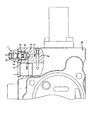
- FIG. 1 is a partial cross-sectional view showing a main part of an embodiment of the present invention.
- FIG. 2 is a partial cross-sectional view showing a main part of a related control valve device.
- FIG. 1 is a partial sectional view showing an embodiment of the present invention.
- the same components as those in the control valve device shown in FIG. 2 will be described using the same reference numerals.
- a spool (not shown) is slidably incorporated in the valve main body B in the present embodiment. Further, the valve main body B is formed with an actuator port 1 connected to an actuator (not shown).
- the control valve device is configured to communicate the actuator port 1 with the supply side of the working fluid or communicate with the return side according to the moving position of the spool.
- the valve main body B has a built-in hole 2 into which the on-off valve V is incorporated.
- the built-in hole 2 is opened in the surface of the valve main body B in which the opening of the actuator port 1 is formed.
- the on-off valve V has a valve main body 11, a poppet member 12 incorporated in the on-off valve main body 11 so as to be movable in the axial direction, and a seat member 13.
- the valve body 11 is fixed to the valve main body B with screws 14.
- the seat member 13 is sandwiched between the valve body 11 and the bottom 2 a of the assembly hole 2.
- the poppet member 12 that is movably incorporated in the valve body 11 is configured to open and close the seat portion 13a formed on the seat member 13 by the poppet portion 12a formed at the tip thereof.
- a small diameter portion 12b is formed on the side opposite to the poppet portion 12a, and the small diameter portion 12b protrudes outward from a small hole 15 formed in the valve body 11. The protruding end of the small diameter portion 12b is held by a plug 16 screwed to the valve body 11.
- the poppet member 12 is formed with an annular convex portion 12c at the root of the small diameter portion 12b, more specifically, and a step portion 17 is formed at the opening portion of the small hole 15.
- the annular convex portion 12c and the step portion 17 constitute a retaining mechanism. This retaining mechanism prevents the poppet member 12 from slipping out of the valve body 11 and the working fluid from flowing out. Further, the poppet member 12 is movable only between the sheet portion 13 a and the step portion 17.
- An orifice 18 is formed in the seat member 13 of the on-off valve V.
- the communication path 8 and the drain port 9 communicate with each other through the orifice 18 and the seat portion 13a.
- the poppet member 12 is inserted into the valve body 11 in advance, and the small diameter portion 12 b is inserted through the small hole 15. At this time, the poppet member 12 is prevented from falling off from the valve body 11 by the friction of the seal member 19.
- the sheet member 13 is inserted into the assembly hole 2 and the sheet member 13 is brought into close contact with the bottom 2a.
- the valve body 11 with the poppet member 12 assembled in advance is inserted into the assembly hole 2 while rotating, and the screw 14 is tightened.
- the operator can connect the plug 16 of the on-off valve V communicating with the actuator port 1 connected to the boom cylinder. Loosen.
- the poppet member 12 is moved by the action of the load pressure of the boom cylinder until the annular convex portion 12c hits the step portion 17 and opens the seat portion 13a.
- the actuator port 1 communicates with the drain port 9 via the communication path 8, the orifice 18, and the seat portion 13a. Therefore, the return fluid from the boom cylinder is drained from the drain port 9 while being restricted by the orifice 18. Accordingly, the boom cylinder lowers the bucket to a predetermined position while slowly contracting by the amount of the restriction resistance of the orifice 18.
- the seat member 13 in which the orifice 18 is formed can be freely selected with respect to the valve main body B.
- the orifice 18 can be freely set together with the seat member 13. Can be selected.
- the on-off valve V is provided with a retaining mechanism, there is no fear that the poppet member 12 is detached from the valve main body B and the working fluid is ejected to the outside.
- working fluid in this invention includes hydraulic oil, water, gas, and the like.
- the control provided with the on-off valve V for returning the working fluid in the actuator to the drain port 9.
- the present invention relates to a valve device.
- an on-off valve V is incorporated in the valve main body B.
- the on-off valve V includes a seat member 13 incorporated in the valve main body B, an orifice 18 formed in the seat member 13, and a poppet member 12 that opens and closes the seat portion 13 a of the seat member 13.
- This control valve device causes the actuator port 1 to communicate with the drain port 9 when the on-off valve V is opened. At this time, the orifice 18 formed in the sheet member 13 gives a throttle resistance to the working fluid guided to the drain port 9 and restricts the moving speed of the actuator.
- the seat member 13 of the on-off valve V is incorporated in the valve main body B and the orifice 18 is formed in the seat member 13, only the seat member 13 is replaced with respect to the valve main body B. Accordingly, the orifice diameter can be freely selected. Therefore, the orifice diameter of the on-off valve V can be freely changed while using the valve main body B in common. That is, the problem that the valve main body B has to be changed every time the orifice diameter is different can be solved.
- the on-off valve V has a valve body 11 that holds the poppet member 12 so as to be movable.
- the seat member 13 and the valve body 11 are incorporated in the valve main body B.
- a stepped portion 17 is formed on the valve body 11, and an annular convex portion 12 c is formed on the poppet member 12.
- the stepped portion 17 and the annular convex portion 12c form a retaining mechanism for the poppet member 12. Therefore, even if the plug 16 is removed from the valve body 11, the poppet member 12 is pressed by the retaining mechanism.
- the poppet member 12 since the poppet member 12 is pressed by the retaining mechanism, the poppet member 12 does not come out of the valve body 11.
- This embodiment is used as a control valve device used in construction machinery such as a power shovel. For example, when a spool of a control valve that controls a boom is locked in a state where the boom is raised, the boom is lowered and the bucket is forced It is most suitable as a device for lowering to the ground.
Landscapes
- Engineering & Computer Science (AREA)
- General Engineering & Computer Science (AREA)
- Mechanical Engineering (AREA)
- Physics & Mathematics (AREA)
- Fluid Mechanics (AREA)
- Mining & Mineral Resources (AREA)
- Civil Engineering (AREA)
- Structural Engineering (AREA)
- Chemical & Material Sciences (AREA)
- Analytical Chemistry (AREA)
- Lift Valve (AREA)
- Fluid-Pressure Circuits (AREA)
Abstract
Description
Claims (2)
- アクチュエータに接続されるアクチュエータポートが形成されるバルブメインボディと、
前記バルブメインボディに形成され、前記アクチュエータポートとドレンポートとを連通する連通路と、
前記連通路と前記ドレンポートとの間に設けられる開閉弁とを備え、
前記開閉弁は、
前記バルブメインボディに組み込まれたシート部材と、
前記シート部材に設けられたオリフィスと、
前記シート部材のシート部を開閉するポペット部材と、
を備えた制御弁装置。 - 請求項1に記載の制御弁装置であって、
前記開閉弁は、
前記ポペット部材を移動可能に保持する弁本体と、
前記弁本体に形成される段部と、
前記ポペット部材に形成される環状凸部と、をさらに備え、
前記環状凸部と前記段部とにより抜止め機構が形成される制御弁装置。
Priority Applications (4)
| Application Number | Priority Date | Filing Date | Title |
|---|---|---|---|
| CN201580058637.9A CN107148518A (zh) | 2014-11-07 | 2015-10-28 | 控制阀装置 |
| US15/524,914 US10415717B2 (en) | 2014-11-07 | 2015-10-28 | Control valve device |
| DE112015005067.1T DE112015005067T5 (de) | 2014-11-07 | 2015-10-28 | Steuerventilvorrichtung |
| KR1020177009695A KR20170052669A (ko) | 2014-11-07 | 2015-10-28 | 제어 밸브 장치 |
Applications Claiming Priority (2)
| Application Number | Priority Date | Filing Date | Title |
|---|---|---|---|
| JP2014227014A JP5950980B2 (ja) | 2014-11-07 | 2014-11-07 | 制御弁装置 |
| JP2014-227014 | 2014-11-07 |
Publications (1)
| Publication Number | Publication Date |
|---|---|
| WO2016072333A1 true WO2016072333A1 (ja) | 2016-05-12 |
Family
ID=55909059
Family Applications (1)
| Application Number | Title | Priority Date | Filing Date |
|---|---|---|---|
| PCT/JP2015/080445 Ceased WO2016072333A1 (ja) | 2014-11-07 | 2015-10-28 | 制御弁装置 |
Country Status (6)
| Country | Link |
|---|---|
| US (1) | US10415717B2 (ja) |
| JP (1) | JP5950980B2 (ja) |
| KR (1) | KR20170052669A (ja) |
| CN (1) | CN107148518A (ja) |
| DE (1) | DE112015005067T5 (ja) |
| WO (1) | WO2016072333A1 (ja) |
Cited By (1)
| Publication number | Priority date | Publication date | Assignee | Title |
|---|---|---|---|---|
| CN111379765A (zh) * | 2018-12-26 | 2020-07-07 | 纳博特斯克有限公司 | 工作流体监视传感器和流体压驱动装置 |
Families Citing this family (2)
| Publication number | Priority date | Publication date | Assignee | Title |
|---|---|---|---|---|
| KR102173351B1 (ko) * | 2019-01-28 | 2020-11-03 | 한영숙 | 유압 밸브 장치 |
| JP7662802B2 (ja) * | 2021-09-27 | 2025-04-15 | 富士フイルム株式会社 | 画像処理装置、画像処理方法、及びプログラム |
Citations (3)
| Publication number | Priority date | Publication date | Assignee | Title |
|---|---|---|---|---|
| JPH04285307A (ja) * | 1991-03-13 | 1992-10-09 | Nippei Toyama Corp | 油圧回路における安全装置ならびに圧抜き弁 |
| JPH09229010A (ja) * | 1995-11-01 | 1997-09-02 | Kayaba Ind Co Ltd | シリンダの降下防止装置 |
| US20060108185A1 (en) * | 2004-11-23 | 2006-05-25 | Deere & Company, A Delaware Corporation. | Hydraulic system |
Family Cites Families (13)
| Publication number | Priority date | Publication date | Assignee | Title |
|---|---|---|---|---|
| US1668453A (en) * | 1927-05-04 | 1928-05-01 | Cons Ashcroft Hancock Co | Valve |
| US2431769A (en) * | 1943-04-30 | 1947-12-02 | Parker Appliance Co | Quick opening check valve assembly |
| US4566486A (en) * | 1982-03-08 | 1986-01-28 | Taylor Julian S | Soft seat for safety valve |
| US4679765A (en) * | 1986-04-14 | 1987-07-14 | Deere & Company | Low leakage orifice-controlled poppet valve |
| JPH05302682A (ja) | 1992-04-28 | 1993-11-16 | Toshiba Mach Co Ltd | リリーフ弁 |
| JPH11230106A (ja) * | 1998-02-10 | 1999-08-27 | Kayaba Ind Co Ltd | 油圧制御装置 |
| JP2000018205A (ja) * | 1998-06-26 | 2000-01-18 | Hitachi Constr Mach Co Ltd | 圧力補償付き方向切換弁装置 |
| JP4252178B2 (ja) * | 1998-12-04 | 2009-04-08 | 東芝機械株式会社 | リリーフ弁 |
| JP2008281208A (ja) * | 1998-12-04 | 2008-11-20 | Toshiba Mach Co Ltd | リリーフ弁 |
| JP4083962B2 (ja) | 2000-09-04 | 2008-04-30 | カヤバ工業株式会社 | 油圧制御装置 |
| JP2009209999A (ja) | 2008-03-03 | 2009-09-17 | Kayaba Ind Co Ltd | 制御弁装置 |
| JP5111323B2 (ja) * | 2008-10-08 | 2013-01-09 | 東芝機械株式会社 | ハイブリッド型建設機械の駆動装置 |
| CN203756088U (zh) | 2014-04-09 | 2014-08-06 | 刘璞 | 内置阀套式洗井阀 |
-
2014
- 2014-11-07 JP JP2014227014A patent/JP5950980B2/ja active Active
-
2015
- 2015-10-28 US US15/524,914 patent/US10415717B2/en active Active
- 2015-10-28 KR KR1020177009695A patent/KR20170052669A/ko not_active Ceased
- 2015-10-28 DE DE112015005067.1T patent/DE112015005067T5/de not_active Ceased
- 2015-10-28 WO PCT/JP2015/080445 patent/WO2016072333A1/ja not_active Ceased
- 2015-10-28 CN CN201580058637.9A patent/CN107148518A/zh active Pending
Patent Citations (3)
| Publication number | Priority date | Publication date | Assignee | Title |
|---|---|---|---|---|
| JPH04285307A (ja) * | 1991-03-13 | 1992-10-09 | Nippei Toyama Corp | 油圧回路における安全装置ならびに圧抜き弁 |
| JPH09229010A (ja) * | 1995-11-01 | 1997-09-02 | Kayaba Ind Co Ltd | シリンダの降下防止装置 |
| US20060108185A1 (en) * | 2004-11-23 | 2006-05-25 | Deere & Company, A Delaware Corporation. | Hydraulic system |
Cited By (1)
| Publication number | Priority date | Publication date | Assignee | Title |
|---|---|---|---|---|
| CN111379765A (zh) * | 2018-12-26 | 2020-07-07 | 纳博特斯克有限公司 | 工作流体监视传感器和流体压驱动装置 |
Also Published As
| Publication number | Publication date |
|---|---|
| DE112015005067T5 (de) | 2017-07-20 |
| KR20170052669A (ko) | 2017-05-12 |
| CN107148518A (zh) | 2017-09-08 |
| US20170350524A1 (en) | 2017-12-07 |
| JP5950980B2 (ja) | 2016-07-13 |
| JP2016089992A (ja) | 2016-05-23 |
| US10415717B2 (en) | 2019-09-17 |
Similar Documents
| Publication | Publication Date | Title |
|---|---|---|
| CN104919187B (zh) | 流体压控制装置 | |
| EP3354905B1 (en) | Fluid pressure control device | |
| KR101718835B1 (ko) | 건설기계의 유압제어밸브 | |
| JP6159629B2 (ja) | 流体圧制御装置 | |
| JP6397715B2 (ja) | 流体圧制御装置 | |
| CN104968947A (zh) | 工程机械用压力控制阀 | |
| JP5848721B2 (ja) | 緩衝弁 | |
| WO2016072333A1 (ja) | 制御弁装置 | |
| JP5984871B2 (ja) | 制御弁装置 | |
| JP6857571B2 (ja) | 流体圧制御装置 | |
| CN108368860A (zh) | 阀装置 | |
| JP6502813B2 (ja) | 流体圧制御装置 | |
| CN104653537B (zh) | 带锁换向阀 | |
| US10145391B2 (en) | Fluid pressure control device for construction machine | |
| JP6706170B2 (ja) | 流体圧制御装置 | |
| CN105408639A (zh) | 用于工程机械的流量控制阀 | |
| JP5872283B2 (ja) | 圧抜き弁 | |
| KR100998611B1 (ko) | 건설중장비용 홀딩밸브 | |
| JP6981804B2 (ja) | 方向切換弁 | |
| KR20140104814A (ko) | 컨트롤밸브 및 이를 구비하는 유압식 건설장비 | |
| CN106232907A (zh) | 用于工程机械的流量控制阀 | |
| KR20140052130A (ko) | 파일롯 작동 방식의 독립형 툴 밸브 제어 시스템 |
Legal Events
| Date | Code | Title | Description |
|---|---|---|---|
| 121 | Ep: the epo has been informed by wipo that ep was designated in this application |
Ref document number: 15857634 Country of ref document: EP Kind code of ref document: A1 |
|
| ENP | Entry into the national phase |
Ref document number: 20177009695 Country of ref document: KR Kind code of ref document: A |
|
| WWE | Wipo information: entry into national phase |
Ref document number: 15524914 Country of ref document: US |
|
| WWE | Wipo information: entry into national phase |
Ref document number: 112015005067 Country of ref document: DE |
|
| 122 | Ep: pct application non-entry in european phase |
Ref document number: 15857634 Country of ref document: EP Kind code of ref document: A1 |