WO2016067945A1 - 重荷重用空気入りタイヤ - Google Patents
重荷重用空気入りタイヤ Download PDFInfo
- Publication number
- WO2016067945A1 WO2016067945A1 PCT/JP2015/079409 JP2015079409W WO2016067945A1 WO 2016067945 A1 WO2016067945 A1 WO 2016067945A1 JP 2015079409 W JP2015079409 W JP 2015079409W WO 2016067945 A1 WO2016067945 A1 WO 2016067945A1
- Authority
- WO
- WIPO (PCT)
- Prior art keywords
- groove
- tire
- belt
- width
- circumferential
- Prior art date
- Legal status (The legal status is an assumption and is not a legal conclusion. Google has not performed a legal analysis and makes no representation as to the accuracy of the status listed.)
- Ceased
Links
Images




Classifications
-
- B—PERFORMING OPERATIONS; TRANSPORTING
- B60—VEHICLES IN GENERAL
- B60C—VEHICLE TYRES; TYRE INFLATION; TYRE CHANGING; CONNECTING VALVES TO INFLATABLE ELASTIC BODIES IN GENERAL; DEVICES OR ARRANGEMENTS RELATED TO TYRES
- B60C11/00—Tyre tread bands; Tread patterns; Anti-skid inserts
- B60C11/03—Tread patterns
-
- B—PERFORMING OPERATIONS; TRANSPORTING
- B60—VEHICLES IN GENERAL
- B60C—VEHICLE TYRES; TYRE INFLATION; TYRE CHANGING; CONNECTING VALVES TO INFLATABLE ELASTIC BODIES IN GENERAL; DEVICES OR ARRANGEMENTS RELATED TO TYRES
- B60C11/00—Tyre tread bands; Tread patterns; Anti-skid inserts
- B60C11/03—Tread patterns
- B60C11/11—Tread patterns in which the raised area of the pattern consists only of isolated elements, e.g. blocks
-
- B—PERFORMING OPERATIONS; TRANSPORTING
- B60—VEHICLES IN GENERAL
- B60C—VEHICLE TYRES; TYRE INFLATION; TYRE CHANGING; CONNECTING VALVES TO INFLATABLE ELASTIC BODIES IN GENERAL; DEVICES OR ARRANGEMENTS RELATED TO TYRES
- B60C11/00—Tyre tread bands; Tread patterns; Anti-skid inserts
- B60C11/03—Tread patterns
- B60C11/0304—Asymmetric patterns
-
- B—PERFORMING OPERATIONS; TRANSPORTING
- B60—VEHICLES IN GENERAL
- B60C—VEHICLE TYRES; TYRE INFLATION; TYRE CHANGING; CONNECTING VALVES TO INFLATABLE ELASTIC BODIES IN GENERAL; DEVICES OR ARRANGEMENTS RELATED TO TYRES
- B60C11/00—Tyre tread bands; Tread patterns; Anti-skid inserts
- B60C11/03—Tread patterns
- B60C11/0311—Patterns comprising tread lugs arranged parallel or oblique to the axis of rotation
-
- B—PERFORMING OPERATIONS; TRANSPORTING
- B60—VEHICLES IN GENERAL
- B60C—VEHICLE TYRES; TYRE INFLATION; TYRE CHANGING; CONNECTING VALVES TO INFLATABLE ELASTIC BODIES IN GENERAL; DEVICES OR ARRANGEMENTS RELATED TO TYRES
- B60C11/00—Tyre tread bands; Tread patterns; Anti-skid inserts
- B60C11/03—Tread patterns
- B60C11/13—Tread patterns characterised by the groove cross-section, e.g. for buttressing or preventing stone-trapping
-
- B—PERFORMING OPERATIONS; TRANSPORTING
- B60—VEHICLES IN GENERAL
- B60C—VEHICLE TYRES; TYRE INFLATION; TYRE CHANGING; CONNECTING VALVES TO INFLATABLE ELASTIC BODIES IN GENERAL; DEVICES OR ARRANGEMENTS RELATED TO TYRES
- B60C9/00—Reinforcements or ply arrangement of pneumatic tyres
- B60C9/18—Structure or arrangement of belts or breakers, crown-reinforcing or cushioning layers
-
- B—PERFORMING OPERATIONS; TRANSPORTING
- B60—VEHICLES IN GENERAL
- B60C—VEHICLE TYRES; TYRE INFLATION; TYRE CHANGING; CONNECTING VALVES TO INFLATABLE ELASTIC BODIES IN GENERAL; DEVICES OR ARRANGEMENTS RELATED TO TYRES
- B60C9/00—Reinforcements or ply arrangement of pneumatic tyres
- B60C9/18—Structure or arrangement of belts or breakers, crown-reinforcing or cushioning layers
- B60C9/20—Structure or arrangement of belts or breakers, crown-reinforcing or cushioning layers built-up from rubberised plies each having all cords arranged substantially parallel
-
- B—PERFORMING OPERATIONS; TRANSPORTING
- B60—VEHICLES IN GENERAL
- B60C—VEHICLE TYRES; TYRE INFLATION; TYRE CHANGING; CONNECTING VALVES TO INFLATABLE ELASTIC BODIES IN GENERAL; DEVICES OR ARRANGEMENTS RELATED TO TYRES
- B60C9/00—Reinforcements or ply arrangement of pneumatic tyres
- B60C9/18—Structure or arrangement of belts or breakers, crown-reinforcing or cushioning layers
- B60C2009/1871—Structure or arrangement of belts or breakers, crown-reinforcing or cushioning layers with flat cushions or shear layers between belt layers
-
- B—PERFORMING OPERATIONS; TRANSPORTING
- B60—VEHICLES IN GENERAL
- B60C—VEHICLE TYRES; TYRE INFLATION; TYRE CHANGING; CONNECTING VALVES TO INFLATABLE ELASTIC BODIES IN GENERAL; DEVICES OR ARRANGEMENTS RELATED TO TYRES
- B60C11/00—Tyre tread bands; Tread patterns; Anti-skid inserts
- B60C11/03—Tread patterns
- B60C2011/0337—Tread patterns characterised by particular design features of the pattern
- B60C2011/0339—Grooves
- B60C2011/0341—Circumferential grooves
- B60C2011/0344—Circumferential grooves provided at the equatorial plane
-
- B—PERFORMING OPERATIONS; TRANSPORTING
- B60—VEHICLES IN GENERAL
- B60C—VEHICLE TYRES; TYRE INFLATION; TYRE CHANGING; CONNECTING VALVES TO INFLATABLE ELASTIC BODIES IN GENERAL; DEVICES OR ARRANGEMENTS RELATED TO TYRES
- B60C11/00—Tyre tread bands; Tread patterns; Anti-skid inserts
- B60C11/03—Tread patterns
- B60C2011/0337—Tread patterns characterised by particular design features of the pattern
- B60C2011/0339—Grooves
- B60C2011/0341—Circumferential grooves
- B60C2011/0346—Circumferential grooves with zigzag shape
-
- B—PERFORMING OPERATIONS; TRANSPORTING
- B60—VEHICLES IN GENERAL
- B60C—VEHICLE TYRES; TYRE INFLATION; TYRE CHANGING; CONNECTING VALVES TO INFLATABLE ELASTIC BODIES IN GENERAL; DEVICES OR ARRANGEMENTS RELATED TO TYRES
- B60C11/00—Tyre tread bands; Tread patterns; Anti-skid inserts
- B60C11/03—Tread patterns
- B60C2011/0337—Tread patterns characterised by particular design features of the pattern
- B60C2011/0339—Grooves
- B60C2011/0341—Circumferential grooves
- B60C2011/0348—Narrow grooves, i.e. having a width of less than 4 mm
-
- B—PERFORMING OPERATIONS; TRANSPORTING
- B60—VEHICLES IN GENERAL
- B60C—VEHICLE TYRES; TYRE INFLATION; TYRE CHANGING; CONNECTING VALVES TO INFLATABLE ELASTIC BODIES IN GENERAL; DEVICES OR ARRANGEMENTS RELATED TO TYRES
- B60C11/00—Tyre tread bands; Tread patterns; Anti-skid inserts
- B60C11/03—Tread patterns
- B60C2011/0337—Tread patterns characterised by particular design features of the pattern
- B60C2011/0339—Grooves
- B60C2011/0341—Circumferential grooves
- B60C2011/0351—Shallow grooves, i.e. having a depth of less than 50% of other grooves
-
- B—PERFORMING OPERATIONS; TRANSPORTING
- B60—VEHICLES IN GENERAL
- B60C—VEHICLE TYRES; TYRE INFLATION; TYRE CHANGING; CONNECTING VALVES TO INFLATABLE ELASTIC BODIES IN GENERAL; DEVICES OR ARRANGEMENTS RELATED TO TYRES
- B60C11/00—Tyre tread bands; Tread patterns; Anti-skid inserts
- B60C11/03—Tread patterns
- B60C2011/0337—Tread patterns characterised by particular design features of the pattern
- B60C2011/0339—Grooves
- B60C2011/0341—Circumferential grooves
- B60C2011/0353—Circumferential grooves characterised by width
-
- B—PERFORMING OPERATIONS; TRANSPORTING
- B60—VEHICLES IN GENERAL
- B60C—VEHICLE TYRES; TYRE INFLATION; TYRE CHANGING; CONNECTING VALVES TO INFLATABLE ELASTIC BODIES IN GENERAL; DEVICES OR ARRANGEMENTS RELATED TO TYRES
- B60C11/00—Tyre tread bands; Tread patterns; Anti-skid inserts
- B60C11/03—Tread patterns
- B60C2011/0337—Tread patterns characterised by particular design features of the pattern
- B60C2011/0339—Grooves
- B60C2011/0341—Circumferential grooves
- B60C2011/0355—Circumferential grooves characterised by depth
-
- B—PERFORMING OPERATIONS; TRANSPORTING
- B60—VEHICLES IN GENERAL
- B60C—VEHICLE TYRES; TYRE INFLATION; TYRE CHANGING; CONNECTING VALVES TO INFLATABLE ELASTIC BODIES IN GENERAL; DEVICES OR ARRANGEMENTS RELATED TO TYRES
- B60C11/00—Tyre tread bands; Tread patterns; Anti-skid inserts
- B60C11/03—Tread patterns
- B60C2011/0337—Tread patterns characterised by particular design features of the pattern
- B60C2011/0339—Grooves
- B60C2011/0358—Lateral grooves, i.e. having an angle of 45 to 90 degees to the equatorial plane
- B60C2011/0365—Lateral grooves, i.e. having an angle of 45 to 90 degees to the equatorial plane characterised by width
-
- B—PERFORMING OPERATIONS; TRANSPORTING
- B60—VEHICLES IN GENERAL
- B60C—VEHICLE TYRES; TYRE INFLATION; TYRE CHANGING; CONNECTING VALVES TO INFLATABLE ELASTIC BODIES IN GENERAL; DEVICES OR ARRANGEMENTS RELATED TO TYRES
- B60C11/00—Tyre tread bands; Tread patterns; Anti-skid inserts
- B60C11/03—Tread patterns
- B60C2011/0337—Tread patterns characterised by particular design features of the pattern
- B60C2011/0339—Grooves
- B60C2011/0358—Lateral grooves, i.e. having an angle of 45 to 90 degees to the equatorial plane
- B60C2011/0367—Lateral grooves, i.e. having an angle of 45 to 90 degees to the equatorial plane characterised by depth
-
- B—PERFORMING OPERATIONS; TRANSPORTING
- B60—VEHICLES IN GENERAL
- B60C—VEHICLE TYRES; TYRE INFLATION; TYRE CHANGING; CONNECTING VALVES TO INFLATABLE ELASTIC BODIES IN GENERAL; DEVICES OR ARRANGEMENTS RELATED TO TYRES
- B60C11/00—Tyre tread bands; Tread patterns; Anti-skid inserts
- B60C11/03—Tread patterns
- B60C2011/0337—Tread patterns characterised by particular design features of the pattern
- B60C2011/0339—Grooves
- B60C2011/0358—Lateral grooves, i.e. having an angle of 45 to 90 degees to the equatorial plane
- B60C2011/0372—Lateral grooves, i.e. having an angle of 45 to 90 degees to the equatorial plane with particular inclination angles
-
- B—PERFORMING OPERATIONS; TRANSPORTING
- B60—VEHICLES IN GENERAL
- B60C—VEHICLE TYRES; TYRE INFLATION; TYRE CHANGING; CONNECTING VALVES TO INFLATABLE ELASTIC BODIES IN GENERAL; DEVICES OR ARRANGEMENTS RELATED TO TYRES
- B60C11/00—Tyre tread bands; Tread patterns; Anti-skid inserts
- B60C11/03—Tread patterns
- B60C2011/0337—Tread patterns characterised by particular design features of the pattern
- B60C2011/0339—Grooves
- B60C2011/0374—Slant grooves, i.e. having an angle of about 5 to 35 degrees to the equatorial plane
- B60C2011/0376—Slant grooves, i.e. having an angle of about 5 to 35 degrees to the equatorial plane characterised by width
-
- B—PERFORMING OPERATIONS; TRANSPORTING
- B60—VEHICLES IN GENERAL
- B60C—VEHICLE TYRES; TYRE INFLATION; TYRE CHANGING; CONNECTING VALVES TO INFLATABLE ELASTIC BODIES IN GENERAL; DEVICES OR ARRANGEMENTS RELATED TO TYRES
- B60C2200/00—Tyres specially adapted for particular applications
- B60C2200/06—Tyres specially adapted for particular applications for heavy duty vehicles
-
- B—PERFORMING OPERATIONS; TRANSPORTING
- B60—VEHICLES IN GENERAL
- B60C—VEHICLE TYRES; TYRE INFLATION; TYRE CHANGING; CONNECTING VALVES TO INFLATABLE ELASTIC BODIES IN GENERAL; DEVICES OR ARRANGEMENTS RELATED TO TYRES
- B60C2200/00—Tyres specially adapted for particular applications
- B60C2200/06—Tyres specially adapted for particular applications for heavy duty vehicles
- B60C2200/065—Tyres specially adapted for particular applications for heavy duty vehicles for construction vehicles
-
- Y—GENERAL TAGGING OF NEW TECHNOLOGICAL DEVELOPMENTS; GENERAL TAGGING OF CROSS-SECTIONAL TECHNOLOGIES SPANNING OVER SEVERAL SECTIONS OF THE IPC; TECHNICAL SUBJECTS COVERED BY FORMER USPC CROSS-REFERENCE ART COLLECTIONS [XRACs] AND DIGESTS
- Y10—TECHNICAL SUBJECTS COVERED BY FORMER USPC
- Y10T—TECHNICAL SUBJECTS COVERED BY FORMER US CLASSIFICATION
- Y10T152/00—Resilient tires and wheels
- Y10T152/10—Tires, resilient
- Y10T152/10495—Pneumatic tire or inner tube
- Y10T152/10765—Characterized by belt or breaker structure
- Y10T152/10801—Structure made up of two or more sets of plies wherein the reinforcing cords in one set lie in a different angular position relative to those in other sets
Definitions
- the present invention relates to a heavy duty pneumatic tire with a tread pattern.
- Patent Document 1 a heavy-duty pneumatic tire that improves both traction during bad road driving and wet performance during high-speed driving is known (Patent Document 1).
- the circumferential groove extends in the circumferential direction in a tread central region corresponding to 50% of the tread width, (2)
- the groove depth of the circumferential groove is 5% or more of the tread width, (3)
- the groove depth of the transverse grooves provided at least on both sides of the tread is 109% or more of the groove depth of the circumferential grooves. Accordingly, it is described that it is possible to improve both the traction property during rough road traveling and the wet performance during high speed traveling.
- the width of the tread pattern in the tire width direction may be increased.
- the contact pressure near the block edge tends to increase locally.
- a large tire radial force acts on both ends of the belt due to the local increase in the contact pressure.
- Interlayer strain increases.
- separation of the belt edge portion is likely to occur.
- large tires of 49 inches or more for example, mounted on dump trucks traveling on off-roads such as mines, it is possible to improve belt durability by suppressing separation at the belt edge while improving traction performance. From the viewpoint of effectively using the tire.
- an object of the present invention is to provide a pneumatic tire with a tread pattern, which is a heavy duty pneumatic tire capable of improving belt durability while improving traction performance.
- the present disclosure includes the following various forms.
- (Form 1) A heavy duty pneumatic tire with a tread pattern,
- the tread pattern is A center which is provided in plural at intervals in the tire circumferential direction and extends to the first tread region and the second tread region in the tire width direction on the basis of the tire equatorial line so as to cross the tire equatorial line.
- Lug grooves A lug groove provided at a position in the tire circumferential direction between the center lug grooves adjacent to each other in the tire circumferential direction among the plurality of center lug grooves, and extending outward in the tire width direction in each of the half tread regions,
- the tire width direction outer end opens to the ground contact end on both sides of the tire width direction, and the tire width direction position of the tire width direction inner end is compared with the tire width direction position of the end of the center lug groove.
- a shoulder lug groove on the outside in the width direction In each of the half tread regions, the end of the center lug groove and the inner end of the shoulder lug groove in the tire width direction are alternately connected to form a wave shape over the entire circumference of the tire, and the groove is formed from the shoulder lug groove.
- Have The belt portion is The second belt, the third belt, and the third belt having belt widths different from the belt width of the first belt in order from the first belt located at the innermost side in the tire radial direction toward the outer side in the tire radial direction.
- Each pair of belt layers has a ratio W8 / W7 of the belt width W8 of the belt layer with a narrow belt width to the belt width W7 of the belt layer with a wide belt width of 0.75 or more and 0.90 or less, Whether the belt widths of the fourth and subsequent belts from the innermost belt in the tire radial direction in the laminated structure of the belt portion to the outer side in the tire radial direction are the same as the maximum width WB in the tire width direction of the center block.
- a heavy duty pneumatic tire characterized by being wider than the maximum width WB.
- Form 2 The heavy-duty pneumatic tire according to aspect 1, comprising a bottom raised portion in which the groove depth is partially shallow in each of the pair of circumferential main grooves.
- the orientation direction of the reinforcing cord of the belt layer having a wide belt width is a direction inclined from the tire circumferential direction toward the same side in the tire width direction.
- the belt portion includes an innermost first pair in the tire radial direction, a second pair stacked on the outer side in the tire radial direction of the first pair, and a second pair stacked on the outer side in the tire radial direction of the second pair.
- the ratio WB / W3 of the maximum width WB in the tire width direction of the center block to the belt width W3 of the belt layer having a narrow belt width in the third pair is 0.5 to 0.8, and the belt width W3
- the belt portion includes an innermost first pair in the tire radial direction, a second pair stacked on the outer side in the tire radial direction of the first pair, and a second pair stacked on the outer side in the tire radial direction of the second pair. Including 3 pairs, The heavy load air according to any one of modes 1 to 8, wherein a belt width W1 of a belt layer having a narrow belt width in the first pair is narrower than a maximum width WB of the center block in a tire width direction. Enter tire.
- the center lug groove is bent or curved so as to protrude to the third side in the tire circumferential direction on the first side, and the third groove in the tire circumferential direction on the second side.
- a second groove bending portion that bends or curves so as to protrude to the fourth side that is the opposite side of the side,
- the first connection end portion on the first side and the second connection end portion on the second side where the center lug groove is connected to the circumferential main groove are on the inner side in the tire width direction of the circumferential main groove.
- the second connection end of the center lug groove is on the third side in the tire circumferential direction from the first connection end, With respect to the center position in the groove width direction of the center lug groove, the first straight tire width connecting the first connecting end portion and the protruding end at which the first groove bent portion protrudes toward the third side in the tire circumferential direction.
- the circumferential sub-groove is shallower than the circumferential main groove, and the circumferential sub-groove is formed over the entire circumference of the tire along the tire equator line,
- the circumferential sub-groove includes the first groove bent portion and the second groove bent portion, and includes a tire width direction region sandwiched between the first groove bent portion and the second groove bent portion.
- the circumferential sub-groove changes its direction in the clockwise direction when the tread pattern is viewed from the tire radial outer side toward the tire radial inner side when proceeding to the third side in the tire circumferential direction.
- a curved or bent fifth groove bent portion and a curved or bent sixth groove bent portion on the tire circumference so as to change the direction in the counterclockwise direction, and adjacent center lugs of the center lug grooves.
- each of the fifth groove bent portion and the sixth groove bent portion is provided in succession along the tire circumferential direction, and two fifth groove bent portions are provided continuously.
- the circumferential sub-groove includes one of the fifth groove bent portion, one of the fifth groove bent portion, one of the sixth groove bent portion, and one of the sixth groove bent portion, A set arranged in order along the tire circumferential direction as one set, a plurality of sets are provided on the tire circumference, Among the circumferential sub-grooves, a portion between one of the fifth groove bent portions and one of the fifth groove bent portions, and a portion between one of the sixth groove bent portions and one of the sixth groove bent portions.
- the heavy-duty pneumatic tire described above can improve belt durability while improving traction performance.
- the tire width direction refers to the direction of the rotation center axis of the pneumatic tire
- the tire circumferential direction refers to the direction of rotation of the tread surface that occurs when the tire is rotated about the tire rotation center axis.
- the tire radial direction refers to a direction radially extending from the tire rotation center axis.
- the outer side in the tire radial direction refers to the side away from the tire rotation center axis, and the inner side in the tire radial direction refers to the side closer to the tire rotation center axis.
- the outer side in the tire width direction means a side away from the tire equator line in the tire width direction
- the inner side in the tire width direction means a side closer to the tire equator line in the tire width direction.
- the heavy load tire referred to in this specification is one type (dump truck, scraper) described in Chapter D in addition to the tire described in Chapter C of JATMA (Japan Automobile Tire Association Standard) YEAR BOOK 2014. Tires, 2 types (grader) tires, 3 types (excavator loader) tires, 4 types (tire roller) tires, mobile crane (truck crane, wheel crane) tires, or SECTION 4 of TRA 2013 YEAR BOOK Or the vehicle tire described in section 6.
- FIG. 1 is a cross-sectional view of a pneumatic tire of the present embodiment (hereinafter simply referred to as a tire) cut along a plane passing through the tire rotation axis.
- the tire radial direction is indicated by R
- the tire width direction is indicated by W.
- FIG. 2 is a diagram for explaining the belt width of each belt of the belt portion of the present embodiment and the orientation direction of the reinforcing cord.
- the tire 1 has a tread portion 2, a sidewall portion 3, and a bead portion 4.
- the bead part 4 has a pair of bead cores 4a on both sides in the tire width direction.
- a carcass layer 5 is mounted between the pair of bead cores 4a. Both ends of the carcass layer 5 are folded back from the tire inner side to the outer side around the bead core 4a.
- the carcass layer 5 may be composed of a single carcass ply or a plurality of carcass plies.
- a belt portion 6 is provided on the outer side in the tire radial direction of the carcass layer 5 in the tread portion 2.
- the belt portion 6 has a laminated structure in which six belts are laminated along the direction from the inner side to the outer side in the tire radial direction.
- a first cross belt layer 6a, a second cross belt layer 6b, and a third cross belt layer 6c are provided in that order from the inner side to the outer side in the tire radial direction.
- Each of the first cross belt layer 6a, the second cross belt layer 6b, and the third cross belt layer 6c is composed of a pair of belts. As shown in FIG.
- the first cross belt layer 6 a includes a first belt 61 and a second belt 62 from the inside in the tire radial direction to the outside, and the second cross belt layer 6 b is in the tire radial direction.
- a third belt 63 and a fourth belt 64 are provided from the inside toward the outside, and the third cross belt layer 6c has a fifth belt 65 and a sixth belt 66 from the inside in the tire radial direction toward the outside.
- the reinforcing cords are inclined to different sides in the tire width direction with respect to the tire circumferential direction. is doing.
- the belt unit 6 includes two or more pairs, each of which includes the first belt 61 and the second belt 62 as a pair and the third belt 63 and the fourth belt as a pair. That is, the belt portion 6 is viewed in order from the innermost first belt 61 in the tire radial direction toward the outer side in the tire radial direction, and a pair of two belts having different belt widths adjacent to each other in the tire radial direction. It includes (two or more pairs) of cross belt layers and has a laminated structure of cross belt layers. In each pair of crossed belt layers, the ratio W8 / W7 of the belt width W8 of the narrow belt to the belt width W7 of the wide belt is 0.75 or more and 0.90 or less. For example, as shown in FIG.
- the belt width of the first belt 61 corresponds to W7
- the belt width of the second belt 62 corresponds to W8.
- the belt width of the third belt 63 corresponds to W7
- the belt width of the fourth belt 64 corresponds to W8.
- the belt width of the fifth belt 65 corresponds to W7
- the belt width of the sixth belt 66 corresponds to W8.
- the belt width of the belt located on the inner side in the tire radial direction is positioned on the outer side in the tire radial direction. Wide compared to the belt width of the belt. That is, the belt width of the first belt 61 is wider than the belt width 62 of the second belt, the belt width of the third belt 63 is wider than the belt width of the fourth belt 64, and the belt width of the fifth belt 65 is sixth. The belt 66 is wider than the belt width.
- the belt width of the belt located on the inner side in the tire radial direction is the tire radial direction.
- the width of the belt positioned outside may not necessarily be wide.
- the belt width in each pair of cross belt layers is not particularly limited.
- the belt width of the belt having a wide belt width among the plurality of pairs of intersecting belt layers is wider as the belt is located on the outer side in the tire radial direction.
- the belt width of the fifth belt 65 having the wider belt width among 6c the belt width of the first belt 61, the belt width of the third belt 63, and the belt width of the fifth belt 65 are increased in this order.
- the belt portion 6 of the present embodiment has such a belt width, it does not necessarily increase in the order of the belt width of the first belt 61, the belt width of the third belt 63, and the belt width of the fifth belt 65. May be.
- the inclination angle of the lowest reinforcing cord with respect to the tire circumferential direction is 8 to 11 degrees. Alternatively, it is preferably 9 to 11 degrees from the viewpoint that a so-called tagging effect in which the belt suppresses deformation of the tire that tends to expand in the tire radial direction can be effectively obtained.
- the inclination angle of the lowest reinforcing cord among the reinforcing cords of each belt of the second cross belt layer 6b with respect to the tire circumferential direction is 16 to 19 degrees, or 6 to 8 degrees. However, it is preferable from the point which can acquire the tag effect effectively.
- the inclination angle of the lowest reinforcing cord among the reinforcing cords of each belt of the third cross belt layer 16c with respect to the tire circumferential direction is 26 to 29 degrees, or 17 to 19 degrees. It is preferable.
- the lowest inclination angle in the reinforcement cord of each belt of the second cross belt layer 6b is preferably smaller than the lowest inclination angle in the reinforcement cord of each belt of the third cross belt layer 6c. More specifically, the inclination angle of the reinforcing cord of each belt of the belt portion 6 is preferably 8 to 11 degrees for the first belt 61, for example.
- the second belt 62 preferably has an angle of 8 to 11 degrees.
- the angle is preferably 25 to 35 degrees.
- the fourth belt 64 the angle is preferably 16 to 19 degrees.
- the angle is preferably 29 to 35 degrees.
- the sixth belt 66 the angle is preferably 26 to 29 degrees.
- FIG. 3 is a pattern diagram in which a tread pattern provided in the tread portion 2 of the tire 1 is developed in a plane.
- the tire circumferential direction is indicated by C
- the tire width direction is indicated by W.
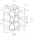
- the tread portion 2 mainly includes a shoulder lug groove 10, a pair of circumferential main grooves 12, a center lug groove 14, a center block 16, and a circumferential sub groove 20 as a tread pattern.
- the shoulder lug groove 10 is formed in each of the half-tread regions on the first side (left side in FIG. 3) and the second side (right side in FIG. 3) in the tire width direction with respect to the tire equator line CL.
- a plurality of tires are provided at intervals in the tire circumferential direction.
- the shoulder lug groove 10 extends outward in the tire width direction in each of the half tread regions on both sides in the tire width direction with respect to the tire equator line CL, and the outer ends in the tire width direction are on both sides in the tire width direction. Open to the tread end (grounding end) 18. As shown in FIG. 1, the tread end 18 is a portion where the outer shapes of the tread portion 2 and the side portion 3 are connected.
- the connection part when the said connection part is rounded, the intersection of the extended line which extended the external shape of the tread part 2 along this shape, and the extended line which extended the external shape of the side part 3 along this shape Say.
- the position of one shoulder lug groove 10 in the tire circumferential direction in one half tread region is the tire of two adjacent shoulder lug grooves in the other half tread region. Between the circumferential positions.
- the shoulder lug groove 10 has a position in the tire width direction at the inner end in the tire width direction of the shoulder lug groove 10 at a position in the tire width direction at the end of the center lug groove 14 to be described later in each half tread region.
- a plurality of shoulder lug grooves 10 are provided at intervals in the tire circumferential direction.
- One shoulder lug groove 10 is provided in a shoulder region between adjacent center lug grooves 14 adjacent to each other in the tire circumferential direction in the center lug groove 14 in the tire circumferential direction.
- the circumferential main groove 12 described later forms a wave shape by alternately connecting the end of the center lug groove 14 and the inner end of the shoulder lug groove 10 in the tire width direction.
- the pair of circumferential main grooves 12 are provided in the first tread region and the second tread region in the tire width direction with respect to the tire equator line CL.
- Each of the circumferential main grooves 12 has a wave shape over the entire circumference of the tire circumference by alternately connecting an end of a center lug groove 14 described later and an inner end of the shoulder lug groove 10 in the tire width direction in each of the half tread regions. Is formed.
- the groove width of the pair of circumferential main grooves 12 is narrower than the groove width of the shoulder lug grooves 10.
- the groove having a wave shape means that the groove meanders in the tire width direction. It may be a rounded curved shape.
- the curved shape includes a shape in which the corner of the rubber block that is in contact with the corner of the groove with a radius of curvature is rounded, that is, a curved shape of the groove formed by chamfering the corner of the rubber block.
- the portion other than the main groove bent portion may be linear or curved.
- the two curved shapes may be curved with the same radius of curvature.
- the two main groove bent portions adjacent to each other in the tire circumferential direction one is a bent main groove bent portion formed by connecting a linear shape and a curved shape groove, and the other is a curved main shape. It is good also as a groove part.
- the circumferential main groove 12 has a plurality of main groove bent portions 11 on the tire circumference that bend in the tire width direction outside and inside, and meanders in a wavy shape in the tire width direction. Extends in the tire circumferential direction.
- Each of the pair of circumferential main grooves 12 is connected to the shoulder lug groove 10 at a third groove bent portion 11a that is bent outwardly in the tire width direction of the main groove bent portion 11.
- each of the pair of circumferential main grooves 12 is connected to the center lug groove 14 at a fourth groove bent portion 11 b that is bent in the tire width direction inside the main groove bent portion 11.
- the center lug groove 14 that connects the fourth groove bent portions 11b in the half-tread region extends in a direction inclined with respect to the tire width direction.
- the wave shape of the pair of circumferential main grooves 12 is These are both wave shapes having a predetermined wavelength, and the phases of the two wave shapes in the tire circumferential direction are shifted from each other by approximately a half pitch.
- the position in the tire circumferential direction of the third groove bent portion 11a of one circumferential main groove 12 of the pair of circumferential main grooves 12 is the third adjacent to the tire circumferential direction of the other circumferential main groove 12. It exists between the positions in the tire circumferential direction of the groove bending part 11a.
- the third groove bent portion 11a of one circumferential main groove 12 and the fourth groove bent portion 11b of the other circumferential main groove 12 are provided at substantially the same position in the tire circumferential direction. It has been.
- a plurality of center lug grooves 14 are provided at intervals in the tire circumferential direction.
- the center lug groove 14 extends in the tire width direction so as to cross the tire equator line CL, and extends to the first tread region and the second tread region in the tire width direction with respect to the tire equator line CL. Has both ends. Both ends of the center lug groove 14 are connected to a fourth groove bent portion 11b which is bent in a convex shape on the inner side in the tire width direction of the main groove bent portion 11 in each of the pair of circumferential main grooves 12.
- the center lug groove 14 intersects the tire equator line CL.
- the center lug groove 14 is provided with a bent first groove bent portion 14a and a second groove bent portion 14b.
- the first groove bent portion 14a and the second groove bent portion 14b are provided in the center lug groove 14, but the first groove bent portion 14a and the second groove bent portion 14b may not be provided.
- FIG. 4 is an enlarged view showing the bent first groove bent portion 14 a and the second groove bent portion 14 b of the center lug groove 14.
- the first groove bent portion 14a is provided in one half tread region, and the second groove bent portion 14b is provided in the other half tread region.
- the first groove bent portion 14a and the second groove bent portion 14b are bent, but may be curved.
- the curved shape includes a shape in which the corner of the rubber block that is in contact with the corner of the groove with a radius of curvature is rounded, that is, a curved shape of the groove formed by chamfering the corner of the rubber block.
- the center lug groove 14 has a first groove bent portion 14a and a second groove bent portion 14b, so that the center lug groove 14 is displaced in a wave shape in the tire circumferential direction.
- the shape of the first groove bent portion 14a and the second groove bent portion 14b is such that, for example, the angle ⁇ (see FIG. 4) of the center lug groove 14 formed by the first groove bent portion 14a and the second groove bent portion 14b is an obtuse angle. It is a shape to become.
- first groove bent portion 14a and the second groove bent portion 14b are provided on both sides of the tire equator line CL in the tire width direction at positions spaced apart from the tire equator line CL by the same distance.
- the tire equator line CL is provided so as to pass through a portion between the first groove bent portion 14a and the second groove bent portion 14b. In this portion, the center lug with respect to the tire width direction is provided.
- the direction of the inclination of the groove 14 is different from the direction of the inclination in the part other than the above part.
- the center lug groove 14 of the present embodiment has a configuration including a linear portion that extends linearly between the pair of circumferential main grooves 12, a first groove bent portion 14a, and a second groove bent portion 14b.
- a curved groove may be used instead of the portion.
- one of the first groove bent portion 14a and the second groove bent portion 14b may be bent and the other may be curved.
- the two curved shapes may be curved shapes having the same curvature radius.
- one of the first groove bent portion 14a and the second groove bent portion 14b is a bent groove bent portion formed by connecting a linear shape and a curved groove, and the other is a curved groove bent. It is good also as a part.
- the shape of the center lug groove 14 is preferably a groove shape extending in the tire width direction while being displaced in the tire circumferential direction into a wave shape.
- FIG. 5 is a diagram illustrating an example of a preferable shape of the center lug groove 14 that defines the shape of the center block 14.
- the first groove bent portion 14a of the center lug groove 14 has a third side in the tire circumferential direction (see FIG. 4) on the first side (the left side in FIG. 4) with respect to the tire equator line CL. 3 is bent or curved so as to protrude toward the upper side in the drawing.
- the second groove bent portion 14b of the center lug groove 14 has a fourth side in the tire circumferential direction on the second side (the right side in the drawing in FIG. 4) with respect to the tire equator line CL (the lower side in the drawing in FIG. 3).
- the fourth side is opposite to the third side.
- the first connection end 14c on the first side where the center lug groove 14 is connected to the circumferential main groove 12 and the second connection end on the second side where the center lug groove 14 is connected to the circumferential main groove 12 The portion 14d corresponds to the inner end of the circumferential main groove 12 in the tire width direction, that is, the fourth groove bent portions 11b and 11b. Since the center lug groove 14 is inclined with respect to the tire width direction, the second connection end 14d of the center lug groove 14 is closer to the third side in the tire circumferential direction than the first connection end 14c (in FIG. 3). On the side of the paper on the top).
- the first groove bent portion 14 a and the first connection projecting from the third side in the tire circumferential direction (upward side in FIG. 3) and the first connection.
- An inclination angle of the first straight line 14e connecting the end portion 14c with respect to the tire width direction an inclination angle greater than 0 degrees and less than 90 degrees
- the second groove bending portion 14b protrude to the fourth side in the tire circumferential direction.
- the inclination angle (inclination angle greater than 0 degree and less than 90 degrees) of the second straight line 14f connecting the protruding end and the second connection end part 14d with respect to the tire width direction is the same as that of the first connection end part 14c of the center lug groove 14 and the second connection end part 14d. It is preferable that the inclination angle of the third straight line 14g connecting the two connection end portions 14d with respect to the tire width direction (inclination angle larger than 0 degree and smaller than 90 degrees) is larger.
- the first groove bent portion 14 a protrudes to the third side in the tire circumferential direction with respect to the center position in the groove width direction of the center lug groove 14.
- the portion of the center lug groove 14 between the end and the first connection end portion 14c is on the first straight line 14e or on the third side with respect to the first straight line 14e, and the second groove bent portion 14b is disposed on the tire circumference.
- the portion of the center lug groove 14 between the protruding end protruding to the fourth side in the direction and the second connection end 14d is on the second straight line 14f or on the fourth side with respect to the second straight line 14f.
- the tread rigidity of the center block 16 can be increased. That is, since the center block 16 has an anisotropic shape defined by the center lug groove 14 inclined in one direction with respect to the tire width direction, the center block 16 kicks away from the road surface from the tire contact surface. When this is done, the center block 16 is deformed by being twisted clockwise or counterclockwise by an anisotropic shape. At this time, since the groove width of the circumferential main groove 12 is narrow, the center block 16 includes a shoulder block adjacent to the circumferential width groove 12 in the tire width direction, a third groove bent portion 11a, and a fourth groove bent portion.
- the center blocks 16 adjacent to each other in the tire circumferential direction across the center lug groove 14 are meshed at the first groove bending portion 14a and the second groove bending portion 14b and function as a single body.
- the tread rigidity of the center block 16 can be increased. By increasing the tread rigidity of the center block 16, it is possible to suppress the twist of the center block 16, and it is possible to suppress wear of a local region of the center block 16 on both sides of the center lug groove 14 in the tire circumferential direction.
- each part of the center block 16 tends to deform and fall down due to the shearing force in the tire circumferential direction received from the road surface.
- the first groove bent portion 14a and the second groove bent portion 14b are provided in the center lug groove 14, the land portions around the first groove bent portion 14a and the second groove bent portion 14b of the center block 16 are formed.
- Two blocks that mesh with each other and are adjacent to each other in the tire circumferential direction function as one block to generate a reaction force. Therefore, the tread rigidity of the center block 16 can be increased by providing the first groove bent portion 14 a and the second groove bent portion 14 b in the center lug groove 14.
- the center block 16 is defined by the center lug groove 14 and the pair of circumferential main grooves 12 and is formed in a plurality in a row in the tire circumferential direction.
- a tire equator line (tire center line) CL passes through the center block 16.
- the circumferential sub-groove 20 is a groove extending in the tire circumferential direction along the tire equator line CL so as to divide the region of the center block 16.
- the circumferential sub-groove 20 is connected to two center lug grooves 14 adjacent in the tire circumferential direction.
- the circumferential sub-groove 20 has a shallower groove depth than the maximum groove depth of the circumferential main groove 12.
- the circumferential sub-groove 20 includes a straight portion extending in parallel with the tire circumferential direction from the center lug groove 14, and a bent fifth groove bent portion that is connected to the straight portion and changes the extending direction of the groove. 21a and the 6th groove bending part 21b, and the inclination part inclined in the tire peripheral direction extended between the 5th groove bending part 21a and the 6th groove bending part 21b.
- the shape of the sixth groove bent portion 21b provided in the circumferential sub groove 20 is such that the bending angle ⁇ (see FIG. 4) of the circumferential sub groove 20 formed by the sixth groove bent portion 21b. The shape is obtuse.
- the bending angle of the circumferential sub-groove 20 formed by the fifth groove bending portion 21a is also an obtuse angle.
- the fifth groove bent portion 21a and the sixth groove bent portion 21b are provided in the circumferential sub-groove 20, the fifth groove bent portion 21a and the sixth groove bent portion 21b are not necessarily provided.
- a fifth groove bent portion 21a and a sixth groove bent portion 21b are provided, but may be one, or may be three or more.
- the linear portion in the circumferential sub-groove 20 may not extend in parallel to the tire circumferential direction.
- the tire equator line CL passes in a portion connecting the fifth groove bent portion 21a and the sixth groove bent portion 21b in the circumferential sub groove 20.
- the circumferential sub-groove 20 is between the first groove bent portion 14a of the center lug groove 14 and the second groove bent portion 14b of the center lug groove 14 adjacent to the center lug groove 14 in the tire circumferential direction.
- the second groove bent portion 14b is a groove bent portion provided in a half tread region different from the half tread region provided with the first groove bent portion 14a.
- the circumferential sub-groove 20 connected to the center lug groove 14 has either one of the first groove bent portion 14a and the second groove bent portion 14b on both sides in the tire circumferential direction (the lower side of the page in FIG. It is preferable to connect from the upper side.
- the fifth groove bent portion 21a and the sixth groove bent in the circumferential sub-groove 20 connecting the two center lug grooves 14 adjacent in the tire circumferential direction In order to achieve such a connection form of the circumferential sub-grooves 20, the fifth groove bent portion 21a and the sixth groove bent in the circumferential sub-groove 20 connecting the two center lug grooves 14 adjacent in the tire circumferential direction.
- the portion 21b it is preferable that the extending direction of the circumferential sub-groove 20 bends in different directions such as clockwise or counterclockwise when proceeding along the tire circumferential direction.
- a preferable form of the circumferential sub-groove 20 is formed over the entire circumference of the tire along the tire equator line CL, and the circumferential sub-groove 20 includes a first groove bent portion 14a and a second groove bent portion 14b. Crossing through the center lug groove 14 and crossing within the region in the tire width direction sandwiched between the 1-groove bent portion 14a and the second-groove bent portion 14b. At this time, when the fifth groove bending 21a proceeds to the third side in the tire circumferential direction, the direction of the fifth groove bending 21a changes in the clockwise direction when the tread pattern is viewed from the outer side in the tire radial direction toward the inner side in the tire radial direction. Curved or bent.
- the direction of the counterclockwise rotation direction changes when the tread pattern is viewed from the tire radial outer side toward the tire radial inner side. Curved or bent.
- the fifth groove bent portion 21a and the sixth groove bent portion 21b are provided on the tire circumference, and the portion of the circumferential sub-groove 20 between the adjacent center lug grooves 14 in the center lug groove 14 is the fifth groove.
- One of the bent portions 21a and one of the sixth groove bent portions 21b are arranged.
- the circumferential sub-groove 20 is provided with two each of the fifth groove bent portion 21a and the sixth groove bent portion 21b continuously along the tire circumferential direction. It is preferable that the center lug groove 14 crosses between the two fifth groove bent portions 21a and the two sixth groove bent portions 21b provided.
- one of the fifth groove bent portion 21a, one of the fifth groove bent portion 21a, one of the sixth groove bent portion 21b, and one of the sixth groove bent portion 21b are provided on the tire circumference, with a set that is arranged in order along the tire circumferential direction as one set.
- a portion between one of the fifth groove bent portion 21a and one of the fifth groove bent portion 21a, one of the sixth groove bent portion 21b, and the sixth groove bent portion 21b is preferably a straight groove extending parallel to the tire equator line CL.
- the shapes of the fifth groove bent portion 21a and the sixth groove bent portion 21b may be curved shapes in addition to the bent shapes.
- the curved shape includes a shape in which the corner of the rubber block that is in contact with the corner of the groove with a radius of curvature is rounded, that is, a curved shape of the groove formed by chamfering the corner of the rubber block.
- One of the two second groove bent portions 21 may be bent and the other may be curved.
- the linear portion of the circumferential sub-groove 20 has a groove shape extending in parallel with the tire circumferential direction, but the linear portion may be curved instead of the groove shape.
- the two curved shapes may be curved shapes having the same curvature radius.
- one of the fifth groove bent portion 21a and the sixth groove bent portion 21b is a bent groove bent portion formed by connecting a linear shape and a curved groove, and the other is a curved groove. It may be a bent part.
- the circumferential sub-groove 20 includes a straight portion, a fifth groove bent portion 21a and a sixth groove bent portion 21b, and an inclined portion. It may be a groove shape extending in the tire circumferential direction while being displaced in the circumferential direction.
- the groove width of the pair of circumferential main grooves 12 is narrower than that of the shoulder lug grooves 10. Therefore, the maximum width WB (see FIG. 3) of the center block 16 in the tire width direction can be increased as compared with the conventional case, and as a result, the traction performance can be improved as compared with the conventional case.
- a large ground pressure acts near the edge of the center block 16. Therefore, the vicinity of the belt end 6 of the belt portion 6 existing at the same position in the tire width direction as the edge of the center block 16 in the tire width direction is likely to receive a large force inward in the tire radial direction. Edge distortion increases, and as a result, separation tends to occur at the belt edge portion. For this reason, in this embodiment, the structure of the belt part 6 is defined as follows.
- the fourth belt 64, the fifth belt 65, The belt width of the sixth belt 66 is the same as the maximum width WB of the center block 16 in the tire width direction or wider than the maximum width WB.
- the circumferential main groove 12 has a wave shape, stress generated due to road surface unevenness can be dispersed on the edge of the center block 16, and the edge portion is cut. It is difficult to become a starting point. Also, by providing the circumferential sub-groove 20 in the area of the center block 16, the envelope property of the center block 16 having a wider maximum width WB compared to the conventional case, that is, the ability to absorb road surface irregularities by deformation of the tread rubber. Can be improved. Thereby, the force applied to the center portion of the belt located in the tire radial direction inner side of the region of the center block 16 can be suppressed.
- each of the pair of circumferential main grooves 12 includes a bottom raised portion 12a in which the groove depth is partially shallow.
- FIG. 6 is a diagram illustrating an example of the bottom raised portion 12a.
- the bottom raised portion 12a is provided in a portion extending between the third groove bent portion 11a and the fourth groove bent portion 11b so as to be inclined with respect to the tire circumferential direction.
- the groove 12 may be provided in a region including the third groove bent portion 11a and the fourth groove bent portion 11b.
- the circumferential main groove 12 has a constant maximum depth region where the groove depth is the deepest, and a portion where the groove depth becomes shallower from this region is the bottom raised portion 12a.
- the deepest groove depth of the circumferential main groove 12 is preferably the same as the shoulder lug groove 10.
- the form of the raised portion 12a may be a form in which the groove depth becomes discontinuously shallow with steps from the maximum depth area, or a form in which the groove depth gradually decreases from the maximum depth area. After the depth becomes shallower, the groove depth may be deepened within a range shallower than the groove depth in the maximum depth region. As described above, the bottom raised portion 12a may have a constant shallow groove depth, but need not have a constant shallow groove depth, and the groove depth may vary.
- the ratio D2 / T is preferably less than 0.05 with respect to the groove depth D2 (see FIG. 6) of the shallowest portion in the bottom raised portion 12a and the tread width T (see FIG. 3) of the tread portion 2. .
- the ratio D2 / T is 0.05 or more, the groove depth of the bottom raised portion 12a becomes deeper than the tread width T. Therefore, it is difficult to suppress the collapse of the center block 16 and the vicinity of the belt end. It is difficult to sufficiently suppress the belt edge distortion.
- the ratio D2 / T is more preferably 0.04 or less, for example 0.03.
- the lower limit of the ratio D2 / T is not particularly limited but is, for example, 0.01.
- the groove depth of the bottom raised portion 12a becomes deeper than the tread width T, so that the block rigidity around the bottom raised portion of the center block 16 and the center portion of the center block 16 ( The difference between the block rigidity of the inner portion away from the edge of the groove having the bottom raised portion is increased, and uneven wear tends to occur.
- the tread width T is a peripheral length along the outer shape of the curved tread portion 2 between the tread ends 18 on both sides in the tire width direction.
- the fifth groove bent portion 21a and the sixth groove bent portion 21b in the circumferential sub-groove 20, there is no fifth groove bent portion 21a and sixth groove bent portion 21b and the circumferential sub groove.
- the force received by the center block 16 from the road surface can be suppressed from being concentrated at the same position in the tire width direction.
- the force applied to the center portion of the belt portion 6 located on the inner side in the tire radial direction of the region of the center block 16 can be dispersed.
- the orientation direction of the reinforcing cord of the wide belt among the plurality of pairs of belts 6 is the tire circumference.
- a direction inclined from the direction toward the same side in the tire width direction is preferable.
- the crossing layer in which the belt reinforcing cords are inclined from the tire circumferential direction toward the different side in the tire width direction is preferable.
- the belt rigidity in the tire circumferential direction can be increased.
- the belt located on the outer side in the tire radial direction has a wider belt width with respect to the belt width of the wide belt among the plural pairs of belts of the belt portion 6.
- the belt width is preferably widened in the order of the first belt 61, the third belt 63, and the fifth belt 65.
- the belt portion 6 is laminated on the outer side in the tire radial direction of the first cross belt layer 6 a and the first cross belt layer 6 a that is the first innermost pair in the tire radial direction.
- the ratio WB / W3 of the maximum width WB of the center block 16 to the belt width W3 (see FIG. 2) of the sixth belt 66 having a narrow belt width in the intersecting belt layer 6c is 0.5 to 0.8.
- the width W3 is preferably wider than the belt width W2 (see FIG.
- the ratio WB / W3 is 0.5 or more and 0.8 or less, and the belt width W3 is wider than the belt width W2, so that the tire radial direction applied to the belt of the tire in the region of the contact surface contacting the road surface of the tread portion 2 Force can be made uniform, belt edge distortion can be reduced, and separation of the belt edge portion can be suppressed.
- the ratio WB / W3 is more preferably 0.55 or more and 0.75 or less.
- the belt width W1 of the second belt 62 having a narrow belt width in the first cross belt layer 6a that is the first innermost pair in the tire radial direction is narrower than the maximum width WB of the center block 16. Is preferred.
- the corner portions when corner portions are formed in the center block 16 corresponding to the circumferential main grooves 12, it is preferable that all the top portions of the center block 16 in contact with the circumferential main grooves 12 are obtuse corner portions. .
- the groove widths of the pair of circumferential main grooves 12 and the center lug groove 14 are preferably 7 to 20 mm. By using such a groove width, the envelope property of the tread portion 2 can be improved, and the force applied to the center portion of the belt can be suppressed.
- the tire 1 is preferably mounted on a construction vehicle or an industrial vehicle.
- Construction vehicles or industrial vehicles include dump trucks, scrapers, graders, excavator loaders, tire rollers, wheel cranes, truck cranes, or vehicles such as COMPACTOR, EARTHMOVER, GRADER, LOADER AND DOZER.
- Example, conventional example, comparative example In order to investigate the effect of the tire of this embodiment, various tires having the structure shown in FIG. 1 but having a different belt width and tread pattern were manufactured, and the separation of the belt edge was examined.
- the prototype tire is 46 / 90R57.
- a separation test was conducted with the rim size 29.00-6.0 (TRA specified rim) and 700 kPa (TRA specified air pressure) and load load 617.81 kPa (TRA standard load) as test conditions.
- the separation test is a test in which the tire is continuously run until separation of the belt occurs at a speed of 15 km / hour with an indoor drum.
- the separation was evaluated by the running time of the tire until the belt edge separation occurred.
- the evaluation result of the interlayer separation of the belt is shown with the above running time as an index based on the running time of the conventional example (index 100). The higher the index, the longer the tire running time and the less the separation is generated.
- FIG. 7 is a diagram showing a tread pattern of a conventional example.
- the tread pattern shown in FIG. 7 includes a shoulder lug groove 110, a pair of circumferential main grooves 112, a center lug groove 114, and a center block 116.
- the shoulder lug groove 110, the pair of circumferential main grooves 112, the center lug groove 114, and the center block 116 are respectively the shoulder lug groove 10, the pair of circumferential main grooves 12, the center lug groove 14, and the center lug groove.
- it has the same configuration as the block 16
- the groove width of the shoulder lug groove 110 and the groove width of the circumferential main groove 112 are the same.
- the groove width of the circumferential main groove 112 is the same as that of the shoulder lug groove 110, the circumferential main groove is not narrower than the width of the shoulder lug groove 10 as in the circumferential main groove 12.
- the wave-shaped circumferential main groove is “none”.
- Comparative Examples 1 to 6 and Examples 1 to 19 the tread pattern shown in FIG. 2 was used.
- Table 1 below shows the inclination angle of the reinforcing cord orientation direction of the belts of the conventional example, comparative examples 1 to 6 and examples 1 to 19 with respect to the tire circumferential direction, and the belt width.
- the belt width is shown in% relative to the maximum width WB of the center block 16 of the tread pattern used in the first embodiment. In Comparative Examples 1 to 6 and Examples 1 to 19, the tread pattern shown in FIG. 2 was used, and the tread width T and the maximum width WB of the center block 16 were fixed to the same size.
- the value of the ratio W8 / W7 for some of Examples 1 to 19 is slightly deviated from the range of 0.75 to 0.90, but by rounding off the third decimal place,
- the value of the ratio W8 / W7 is included in the range of 0.75 to 0.90.
- the orientation directions of the reinforcing cords of the wide belts are the same, and further, an intersecting layer is formed with the belt adjacent in the tire radial direction. It can be seen that (the orientation direction of the reinforcing cord of the belt is inclined from the tire circumferential direction toward the different direction of the tire width direction) is preferable from the viewpoint of suppressing the interlayer separation of the belt.
- the ratio WB / W3 is 0.5 to 0.8 and that the belt width W3 is wider than the belt width W2 from the viewpoint of suppressing the interlayer separation of the belt.
- Examples 15 to 19 indicate that the groove widths of the circumferential main groove 12 and the center lug groove 14 are preferably 7 to 20 mm from the viewpoint of suppressing the interlayer separation of the belt. As mentioned above, the effect of this embodiment is clear.
Landscapes
- Engineering & Computer Science (AREA)
- Mechanical Engineering (AREA)
- Tires In General (AREA)
Abstract
Description
(1)該周方向溝は、トレッド幅の50%に相当するトレッド中央領域内で周方向に延び、
(2)該周方向溝の溝深さがトレッド幅の5%以上で、
(3)該横方向溝の内、少なくともトレッド両側部に具えられた横方向溝の溝深さが該周方向溝の溝深さの109%以上である。
これにより、悪路走行時のトラクション性と高速走行時のウエット性能の両立向上させることができる、と記載されている。
特に、鉱山等のオフロード上を走行するダンプトラックに装着される、例えば49インチ以上の大型タイヤにおいて、トラクション性能を向上しつつ、ベルトエッジ部のセパレーションを抑えてベルト耐久性を向上させることが、タイヤを効果的に使用する点から好ましい。
(形態1)
トレッドパターン付き重荷重用空気入りタイヤであって、
前記トレッドパターンは、
タイヤ周方向に間隔をあけて複数設けられ、タイヤ赤道線を横切るようにタイヤ赤道線を基準としたタイヤ幅方向の第1の側及び第2の側の半トレッド領域に延びて両端を有するセンターラグ溝と、
複数の前記センターラグ溝のうちタイヤ周方向に隣接するセンターラグ溝の間のタイヤ周方向の位置に設けられるラグ溝であって、前記半トレッド領域のそれぞれにおいて、タイヤ幅方向外側に延びて、タイヤ幅方向外側の端がタイヤ幅方向の両側にある接地端に開口し、タイヤ幅方向内側の端のタイヤ幅方向の位置が、前記センターラグ溝の端のタイヤ幅方向の位置に比べてタイヤ幅方向外側にあるショルダーラグ溝と、
前記半トレッド領域のそれぞれにおいて、前記センターラグ溝の端と、前記ショルダーラグ溝のタイヤ幅方向の内側の端を交互に接続してタイヤ周上全周にわたって波形状に形成され、前記ショルダーラグ溝より溝幅が狭い一対の周方向主溝と、
前記センターラグ溝と前記一対の周方向主溝によって画されてタイヤ周方向に一列に複数形成されたセンターブロックと、
前記センターブロックの領域を分割するようにタイヤ赤道線に沿ってタイヤ周方向に延びる周方向副溝と、
を有し、
前記ベルト部は、
タイヤ径方向の最も内側に位置する第1ベルトからタイヤ径方向外側に向かって順番に、前記第1ベルトのベルト幅と異なるベルト幅を有する第2ベルト、第3ベルト、及び前記第3ベルトのベルト幅と異なるベルト幅を有する第4ベルトを少なくとも含み、前記第1ベルトと前記第2ベルト、及び前記第3ベルトと前記第4ベルトをそれぞれ対として、少なくとも2対以上を有する、ベルト層の積層構造を有し、
ベルト層の各対は、ベルト幅が広いベルト層のベルト幅W7に対する、ベルト幅が狭いベルト層のベルト幅W8の比W8/W7は、0.75以上0.90以下であり、
前記ベルト部の前記積層構造におけるタイヤ径方向最内側のベルトからタイヤ径方向外側向かって4番目以降のベルトのべルト幅は、いずれも、前記センターブロックのタイヤ幅方向の最大幅WBと同じか、最大幅WBに比べて広い、ことを特徴とする重荷重用空気入りタイヤ。
前記一対の周方向主溝それぞれにおいて、溝深さが部分的に浅くなった底上げ部を備える、形態1に記載の重荷重用空気入りタイヤ。
前記底上げ部における溝深さをD2、前記トレッド部のタイヤ幅方向のトレッド幅をTとしたとき、D2/T<0.05である、形態2に記載の重荷重用空気入りタイヤ。
前記周方向副溝は、タイヤ周方向に隣接するセンターラグ溝間の領域において、溝の延在方向を変える溝曲がり部を少なくとも2つ備える、形態1~3のいずれか1つに記載の重荷重用空気入りタイヤ。
前記ベルト層の各対のうち、ベルト幅が広いベルト層の補強コードの配向方向は、いずれも、タイヤ周方向からタイヤ幅方向の同じ側に向かって傾斜した方向である、形態1~4のいずれか1つに記載の重荷重用空気入りタイヤ。
前記ベルト部に含まれるベルトのうち隣接するいずれのベルト同士においても、ベルトの補強コードが、タイヤ周方向からタイヤ幅方向の異なる側に向かって傾斜した交差層である、形態1~5のいずれか1つに記載の重荷重用空気入りタイヤ。
前記ベルト層の各対のうち、ベルト幅が広いベルト層のベルト幅に関して、タイヤ径方向外側に位置するベルト層ほど、ベルト幅が広い、形態1~6のいずれか1つに記載の重荷重用空気入りタイヤ。
前記ベルト部は、タイヤ径方向の最も内側の第1の対、前記第1の対のタイヤ径方向外側に積層した第2の対、及び前記第2の対のタイヤ径方向外側に積層した第3の対を含み、
前記第3の対のうちベルト幅の狭いベルト層のベルト幅W3に対する、前記センターブロックのタイヤ幅方向の最大幅WBの比WB/W3は0.5以上0.8以下であり、ベルト幅W3は、前記第2の対のうちベルト幅の狭いベルト層のベルト幅W2より広い、形態1~7のいずれか1つに記載の重荷重用空気入りタイヤ。
前記ベルト部は、タイヤ径方向の最も内側の第1の対、前記第1の対のタイヤ径方向外側に積層した第2の対、及び前記第2の対のタイヤ径方向外側に積層した第3の対を含み、
前記第1の対のうちベルト幅の狭いベルト層のベルト幅W1は、前記センターブロックのタイヤ幅方向の最大幅WBに比べて狭い、形態1~8のいずれか1つに記載の重荷重用空気入りタイヤ。
前記周方向主溝に対応して前記センターブロックに角部が形成され、前記角部のなす角は、鈍角である、形態1~9のいずれか1つに記載の重荷重用空気入りタイヤ。
前記周方向主溝の溝幅および前記センターラグ溝の溝幅は7mm以上20mm以下の範囲にある、形態1~10のいずれか一つに記載の重荷重用空気入りタイヤ。
建設用車両または産業用車両に装着される、形態1~11のいずれか1つに記載の重荷重用空気入りタイヤ。
前記センターラグ溝は、前記第1の側においてタイヤ周方向の第3の側に突出するように屈曲又は湾曲する第1溝曲がり部と、前記第2の側においてタイヤ周方向の前記第3の側の反対側である第4の側に突出するように屈曲又は湾曲する第2溝曲がり部と、を備え、
前記センターラグ溝が前記周方向主溝と接続する前記第1の側の第1接続端部及び前記第2の側の第2接続端部は、前記周方向主溝のタイヤ幅方向の内側の先端と接続し、前記センターラグ溝の前記第2接続端部は、前記第1接続端部よりもタイヤ周方向の第3の側にあり、
前記センターラグ溝の溝幅方向の中心位置に関し、前記第1接続端部と前記第1溝曲がり部がタイヤ周方向の前記第3の側に突出する突出端とを結ぶ第1直線のタイヤ幅方向に対する傾斜角度、および、前記第2接続端部と前記第2溝曲がり部がタイヤ周方向の前記第4の側に突出する突出端とを結ぶ第2直線のタイヤ幅方向に対する傾斜角度は、前記センターラグ溝の前記第1接続端部と前記第2接続端部を結ぶ第3直線のタイヤ幅方向に対する傾斜角度よりも大きい、形態1~12のいずれか1つに記載の重荷重用空気入りタイヤ。
前記センターラグ溝の溝幅方向の中心位置に関し、前記第1溝曲がり部がタイヤ周方向の前記第3の側に突出する突出端と前記第1接続端部との間の前記センターラグ溝の部分は、前記第1直線上、あるいは前記第1直線に対して前記第3の側にあり、前記第2溝曲がり部がタイヤ周方向の前記第4の側に突出する突出端と前記第2接続端部との間の前記センターラグ溝の部分は、前記第2直線上、あるいは前記第2直線に対して前記第4の側にある、形態13に記載の重荷重用空気入りタイヤ。
前記周方向副溝は、前記周方向主溝よりも溝深さが浅く、前記周方向副溝は、タイヤ赤道線に沿ってタイヤ周上全周にわたって形成され、
前記周方向副溝は、前記第1溝曲がり部と前記第2溝曲がり部を含む、前記第1溝曲がり部と前記第2溝曲がり部の間に挟まれたタイヤ幅方向の領域内で前記センターラグ溝を突き抜けて横切るように交差する、形態13または14に記載の重荷重用空気入りタイヤ。
前記周方向副溝には、タイヤ周方向の前記第3の側にすすむとき、タイヤ径方向外側からタイヤ径方向内側に向かって前記トレッドパターンを見たとき、時計回転方向に向きを変えるように、湾曲あるいは屈曲した第5溝曲がり部と、反時計回転方向に向きを変えるように、湾曲あるいは屈曲した第6溝曲がり部がタイヤ周上に設けられ、前記センターラグ溝のうち隣接するセンターラグ溝間にある前記周方向副溝の部分は、前記第5溝曲がり部の1つと前記第6溝曲がり部の1つが配置されている、形態15に記載の重荷重用空気入りタイヤ。
前記周方向副溝には、前記第5溝曲がり部および前記第6溝曲がり部のそれぞれがタイヤ周方向に沿って2つ連続して設けられ、連続して設けられる2つの第5溝曲がり部および2つの第6溝曲がり部のぞれぞれの間で、前記センターラグ溝が横切る、形態16に記載の重荷重用空気入りタイヤ。
前記周方向副溝には、前記第5溝曲がり部の1つ、前記第5溝曲がり部の1つ、前記第6溝曲がり部の1つ、及び前記第6溝曲がり部の1つを、タイヤ周方向に沿って順番に配置した組を1組として、複数組がタイヤ周上に設けられ、
前記周方向副溝のうち、前記第5溝曲がり部の1つと前記第5溝曲がり部の1つの間の部分、及び前記第6溝曲がり部の1つと前記第6溝曲がり部の1つの間の部分は、タイヤ赤道線に平行に延びる直線溝である、形態16または17に記載の重荷重用空気入りタイヤ。
本明細書においてタイヤ幅方向とは、空気入りタイヤの回転中心軸方向をいい、タイヤ周方向とは、タイヤ回転中心軸を中心にタイヤを回転させたときにできるトレッド表面の回転方向をいう。タイヤ径方向とは、タイヤ回転中心軸から放射状に向く方向をいう。タイヤ径方向外側とは、タイヤ回転中心軸から遠ざかる側をいい、タイヤ径方向内側とは、タイヤ回転中心軸に近づく側をいう。また、タイヤ幅方向外側とは、タイヤ赤道線からタイヤ幅方向において遠ざかる側をいい、タイヤ幅方向内側とは、タイヤ幅方向においてタイヤ赤道線に近づく側をいう。
また、本明細書でいう重荷重用タイヤとは、JATMA(日本自動車タイヤ協会規格) YEAR BOOK 2014のC章に記載されるタイヤの他に、D章に記載される1種(ダンプトラック、スクレーバ)用タイヤ、2種(グレーダ)用タイヤ、3種(ショベルローダ等)用タイヤ、4種(タイヤローラ)用タイヤ、モビールクレーン(トラッククレーン、ホイールクレーン)用タイヤ、あるいはTRA 2013 YEAR BOOKのSECTION 4 あるいは、section 6に記載される車両用タイヤをいう。
交差ベルト層の各対は、ベルト幅が広いベルトのベルト幅W7に対する、ベルト幅の狭いベルトのベルト幅W8の比W8/W7は、0.75以上0.90以下である。例えば、図2に示すように、第1の交差ベルト層6aの例で説明すると、第1ベルト61のベルト幅がW7であり、第2ベルト62のベルト幅がW8に対応する。図示されないが、第2の交差ベルト層6bの場合、第3ベルト63のベルト幅がW7であり、第4ベルト64のベルト幅がW8に対応する。同様に、第3の交差ベルト層6cの場合、第5ベルト65のベルト幅がW7であり、第6ベルト66のベルト幅がW8に対応する。
しかし、本実施形態では、第1の交差ベルト層6a、第2の交差ベルト層6b、第3の交差ベルト層6cのそれぞれにおいて、タイヤ径方向内側に位置するベルトのベルト幅は、タイヤ径方向外側に位置するベルトのベルト幅に比べて必ずしも広くなくてもよい。交差ベルト層の各対における上記比W8/W7が、0.75以上0.90以下である限りにおいて、交差ベルト層の各対におけるベルト幅の広い、あるいは狭いについては特に制限されない。
また、複数対の交差ベルト層のうち、ベルト幅が広いベルトのベルト幅に関して、タイヤ径方向外側に位置するベルトほど、ベルト幅が広くなっている。第1の交差ベルト層6aのうちベルト幅の広い第1ベルト61のベルト幅と、第2の交差ベルト層6bのうちベルト幅の広い第3ベルト63のベルト幅と、第3の交差ベルト層6cのうちベルト幅の広い第5ベルト65のベルト幅に関して、第1ベルト61のベルト幅、第3ベルト63のベルト幅、第5ベルト65のベルト幅の順に広くなっている。本実施形態のベルト部6はこのようなベルト幅のベルトを有するが、必ずしも、第1ベルト61のベルト幅、第3ベルト63のベルト幅、第5ベルト65のベルト幅の順に広くなっていなくてもよい。
図3は、タイヤ1のトレッド部2に設けられたトレッドパターンを平面展開したパターン図である。図3中、タイヤ周方向はCで、タイヤ幅方向はWで方向を示している。
トレッド部2は、ショルダーラグ溝10と、一対の周方向主溝12と、センターラグ溝14と、センターブロック16と、周方向副溝20と、をトレッドパターンとして主に備える。
タイヤ幅方向の両側に位置するショルダーラグ溝10において、一方の半トレッド領域における1つのショルダーラグ溝10のタイヤ周方向の位置は、他方の半トレッド領域にある隣接する2つのショルダーラグ溝のタイヤ周方向の位置の間にある。
さらに、ショルダーラグ溝10は、半トレッド領域のそれぞれにおいて、ショルダーラグ溝10が有するタイヤ幅方向内側の端のタイヤ幅方向の位置が、後述するセンターラグ溝14の端のタイヤ幅方向の位置に比べてタイヤ幅方向外側にあり、かつ、ショルダーラグ溝10は、タイヤ周方向に間隔をあけて複数設けられている。ショルダーラグ溝10は、タイヤ周方向において、センターラグ溝14のうちタイヤ周方向に隣りあう隣接センターラグ溝14の間のショルダー領域に1つずつ設けられている。これにより、後述する周方向主溝12は、センターラグ溝14の端とショルダーラグ溝10のタイヤ幅方向の内側の端を交互に接続して波形状を成す。
なお、一対の周方向主溝12の波形状は、いずれも所定の波長を有する波形状であり、この2つの波形状のタイヤ周方向における位相はお互いに略半ピッチずれている。すなわち、一対の周方向主溝12のうち一方の周方向主溝12の第3溝曲がり部11aのタイヤ周方向の位置は、他方の周方向主溝12の、タイヤ周方向に隣り合う第3溝曲がり部11aのタイヤ周方向における位置の間にある。一対の周方向主溝12のうち一方の周方向主溝12の第3溝曲がり部11aと、他方の周方向主溝12の第4溝曲がり部11bとがタイヤ周方向の略同じ位置に設けられている。
センターラグ溝14は、第1溝曲がり部14a及び第2溝曲がり部14bを有することで、タイヤ周方向に波形状に変位する。第1溝曲がり部14a及び第2溝曲がり部14bの形状は、例えばこの第1溝曲がり部14a及び第2溝曲がり部14bによりつくられるセンターラグ溝14の曲がる角度θ(図4参照)が鈍角になる形状である。第1溝曲がり部14a及び第2溝曲がり部14bは、タイヤ赤道線CLのタイヤ幅方向両側に、タイヤ赤道線CLから同じ距離離間した位置に設けられることが好ましい。センターラグ溝14のうち、第1溝曲がり部14aと第2溝曲がり部14bとの間の部分にタイヤ赤道線CLが通過するように設けられ、また、この部分において、タイヤ幅方向に対するセンターラグ溝14の傾斜の向きが、上記部分以外の部分における傾斜の向きと異なっている。
図5に示すように、センターラグ溝14の第1溝曲がり部14aは、タイヤ赤道線CLを基準として第1の側(図4中の紙面左側)においてタイヤ周方向の第3の側(図3中の紙面上方向の側)に突出するように屈曲又は湾曲する。センターラグ溝14の第2溝曲がり部14bは、タイヤ赤道線CLを基準として第2の側(図4中の紙面右側)においてタイヤ周方向の第4の側(図3中の紙面下方向の側)に突出するように屈曲又は湾曲する。第4の側は、第3の側に対して反対側である。ここで、センターラグ溝14が周方向主溝12と接続する第1の側の第1接続端部14c及びセンターラグ溝14が周方向主溝12と接続する第2の側の第2接続端部14dは、周方向主溝12のタイヤ幅方向の内側の先端、すなわち第4溝曲がり部11b,11bに該当する。センターラグ溝14がタイヤ幅方向に対して傾斜しているため、センターラグ溝14の第2接続端部14dは、第1接続端部14cよりもタイヤ周方向の第3の側(図3中の紙面上方向の側)にある。
このとき、センターラグ溝14の溝幅方向の中心位置に関し、第1溝曲がり部14aがタイヤ周方向の第3の側(図3中の上方向の側)に突出する突出端と第1接続端部14cとを結ぶ第1直線14eのタイヤ幅方向に対する傾斜角度(0度より大きく90度より小さい傾斜角度)、および、第2溝曲がり部14bがタイヤ周方向の第4の側に突出する突出端と第2接続端部14dとを結ぶ第2直線14fのタイヤ幅方向に対する傾斜角度(0度より大きく90度より小さい傾斜角度)は、センターラグ溝14の第1接続端部14cと第2接続端部14dを結ぶ第3直線14gのタイヤ幅方向に対する傾斜角度(0度より大きく90度より小さい傾斜角度)よりも大きいことが好ましい。
周方向副溝20には第5溝曲がり部21aと第6溝曲がり部21bが設けられているが、第5溝曲がり部21aと第6溝曲がり部21bは必ずしも設けられなくてもよい。
このとき、第5溝曲がり21aは、タイヤ周方向の第3の側にすすむとき、タイヤ径方向外側からタイヤ径方向内側に向かってトレッドパターンを見たとき、時計回転方向に向きを変えるように、湾曲あるいは屈曲している。第6溝曲がり部21bは、タイヤ周方向の第3の側にすすむとき、タイヤ径方向外側からタイヤ径方向内側に向かってトレッドパターンを見たとき、反時計回転方向に向きを変えるように、湾曲あるいは屈曲している。この第5溝曲がり部21aと第6溝曲がり部21bが、タイヤ周上に設けられ、センターラグ溝14のうち隣接するセンターラグ溝14間にある周方向副溝20の部分は、第5溝曲がり部21aの1つと第6溝曲がり部21bの1つが配置されている。
このとき、図3に示すように、周方向副溝20には、第5溝曲がり部21aおよび第6溝曲がり部21bのそれぞれがタイヤ周方向に沿って2つ連続して設けられ、連続して設けられる2つの第5溝曲がり部21aおよび2つの第6溝曲がり部21bのぞれぞれの間で、センターラグ溝14が横切ることが好ましい。
周方向副溝20の上記直線部はタイヤ周方向に平行に延びる溝形状を有するが、この溝形状に替えて、上記直線部を湾曲形状にしてもよい。第5溝曲がり部21a及び第6溝曲がり部21bを湾曲形状にし、上記直線部を湾曲形状にする場合、2つの湾曲形状は、同じ曲率半径を有する湾曲形状にしてもよい。また、第5溝曲がり部21a及び第6溝曲がり部21bのうち、一方を、直線形状と湾曲形状の溝が接続して形成される屈曲形状の溝曲がり部とし、他方を、湾曲形状の溝曲がり部としてもよい。また、周方向副溝20は、上述したように、直線部と、第5溝曲がり部21a及び第6溝曲がり部21bと、傾斜部とを有するが、この形状に替えて、波形状にタイヤ周方向に変位しながらタイヤ周方向に延びる溝形状であってもよい。
また、センターブロック16の領域に、周方向副溝20を設けることにより、従来に比べて広い最大幅WBを持つセンターブロック16のエンベロープ性、すなわち路面の凹凸をトレッドゴムの変形で吸収する能力を向上させることができる。これより、センターブロック16の領域のタイヤ径方向内側に位置するベルトのセンター部分にかかる力を抑制することができる。
また、一対の周方向主溝12及びセンターラグ溝14の溝幅は、いずれも7~20mmであることが好ましい。このような溝幅を用いることにより、トレッド部2のエンベロープ性を向上させ、ベルトのセンター部分にかかる力を抑制することができる。
なお、タイヤ1は、建設用車両または産業用車両に装着されることが好ましい。建設用車両または産業用車両は、ダンプトラック、スクレーバ、グレーダ、ショベルローダ、タイヤローラ、ホイールクレーン、トラッククレーン、あるいは、COMPACTOR、 EARTHMOVER、GRADER、LOADER AND DOZER等の車両を含む。
本実施形態のタイヤの効果を調べるために、図1に示す構造を有するが、ベルト幅及びトレッドパターンの異なるタイヤを種々試作し、ベルトのエッジのセパレーションを調べた。試作したタイヤは、46/90R57である。リムサイズ29.00-6.0(TRA規定リム)に装着し、700kPa(TRA規定空気圧)、負荷荷重617.81kN(TRA規格荷重)を試験条件として、セパレーション試験を行った。
セパレーション試験は、室内ドラムで速度15km/時とし、ベルトのセパレーションが発生するまでタイヤを連続して走行させる試験である。セパレーションは、ベルトエッジのセパレーションが発生するまでのタイヤの走行時間で評価した。下記表では、上記走行時間を、従来例の走行時間を基準(指数100)とする指数として、ベルトの層間セパレーションの評価結果を表した。指数が高いほど、タイヤ走行時間が長く、セパレーションが生じ難いタイヤであることを意味する。
図7は、従来例のトレッドパターンを示す図である。図7に示すトレッドパターンは、ショルダーラグ溝110と、一対の周方向主溝112と、センターラグ溝114と、センターブロック116と、を備える。ショルダーラグ溝110と、一対の周方向主溝112と、センターラグ溝114と、センターブロック116は、それぞれ、ショルダーラグ溝10と、一対の周方向主溝12と、センターラグ溝14と、センターブロック16と同様な構成を有するが、ショルダーラグ溝110の溝幅と周方向主溝112の溝幅は同じである。周方向主溝112の溝幅がショルダーラグ溝110と同じであることから、周方向主溝12のように、ショルダーラグ溝10の溝幅より狭い周方向主溝ではないので、下記表2では、波形状の周方向主溝は「無し」、としている。
比較例1~6及び実施例1~19は、図2に示すトレッドパターンを用いた。
下記表1は、従来例、比較例1~6、及び実施例1~19のベルトの補強コードの配向方向のタイヤ周方向に対する傾斜角度、及びベルト幅を示している。補強コードの配向方向の傾斜角度における「+」は、タイヤ周方向を上下方向にみて、タイヤ周方向に対して、右上方向に補強コードが傾斜(配向)することを意味し、傾斜角度における「-」は、タイヤ周方向に対して、左上方向に補強コードが傾斜(配向)することを意味する。ベルト幅は、実施例1に用いたトレッドパターンのセンターブロック16の最大幅WBに対する%表示で示している。
比較例1~6及び実施例1~19では、図2に示すトレッドパターンを用い、トレッド幅T及びセンターブロック16の最大幅WBのそれぞれを同じ寸法に固定した。
実施例1~19のうちいくつかについての比W8/W7の値は、厳密には0.75~0.90の範囲から僅かにはずれる例があるが、小数点3桁目を四捨五入することにより、比W8/W7の値は、0.75~0.90の範囲に含まれる。例えば、実施例1の比W8/W7の値は、0.748(=140%/187%)であり、厳密には0.75未満であるが、小数3桁目を四捨五入して0.75となる。実施例3の比W8/W7の値は、0.903(=130%/144%)であり、厳密には0.90より大きいが、小数3桁目を四捨五入して0.90となる。

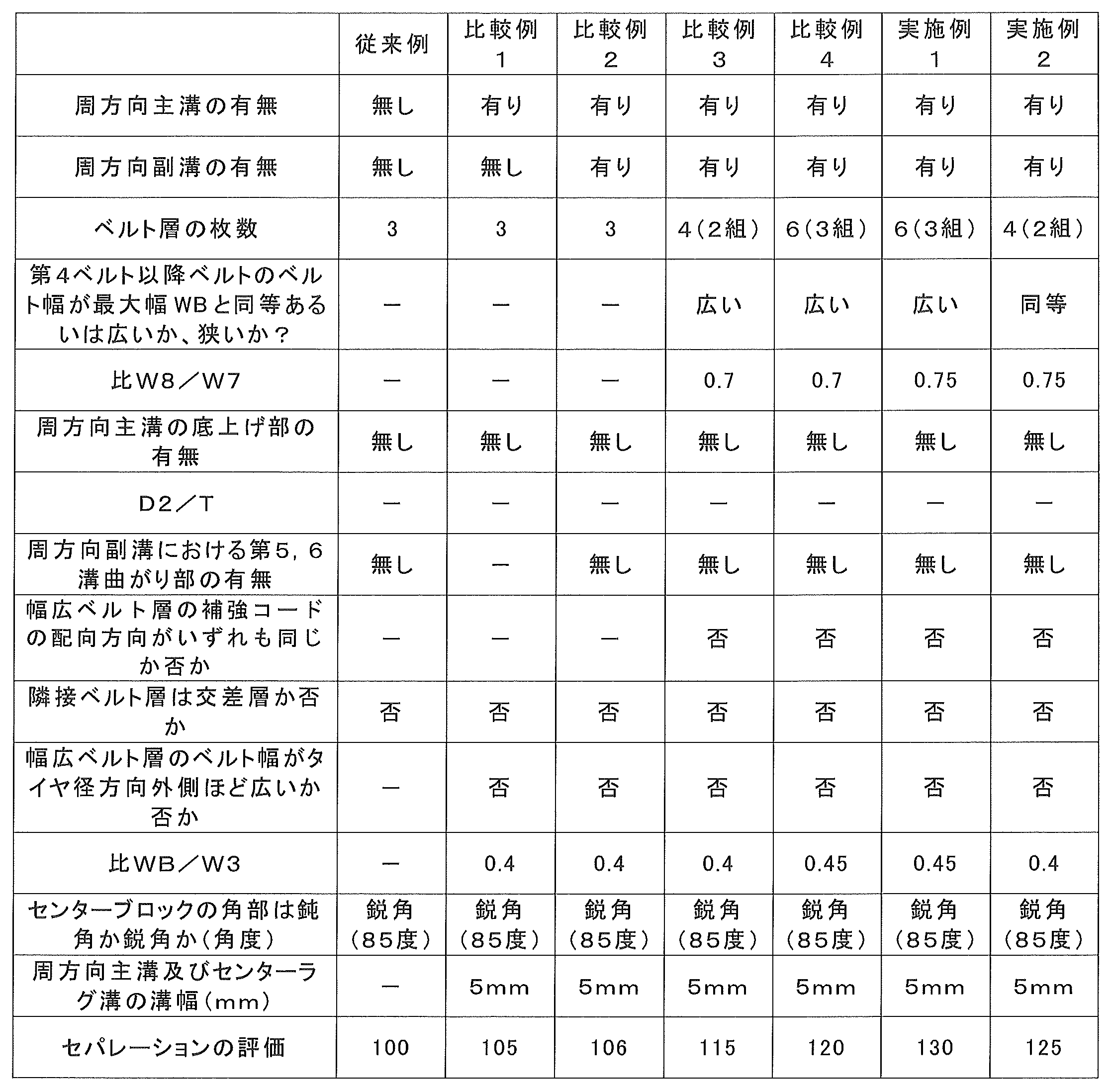
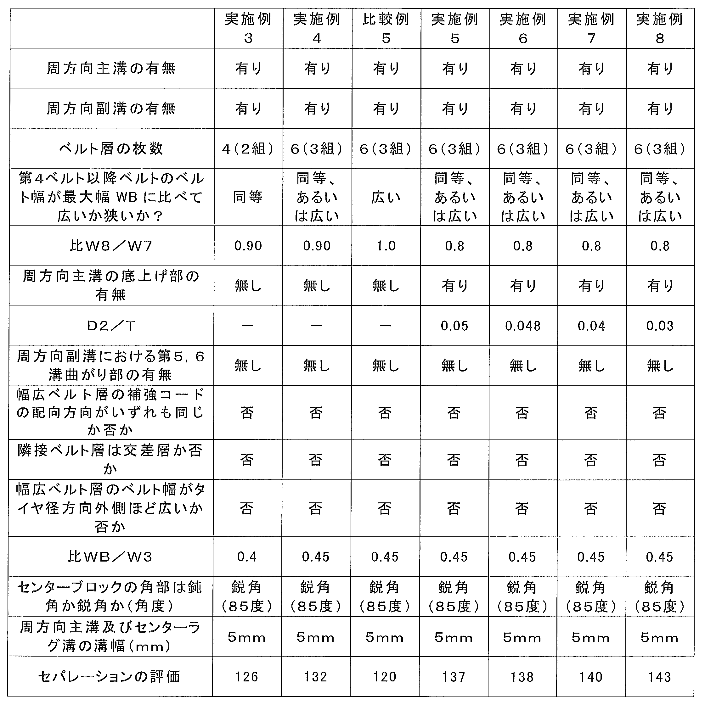

また、実施例5~8より、周方向主溝12に底上げ部12aを設けることがベルトの層間セパレーションを抑える点から好ましく、さらに、そのとき、D2/Tは0.5未満、好ましくは0.48以下あることが好ましいことがわかる。
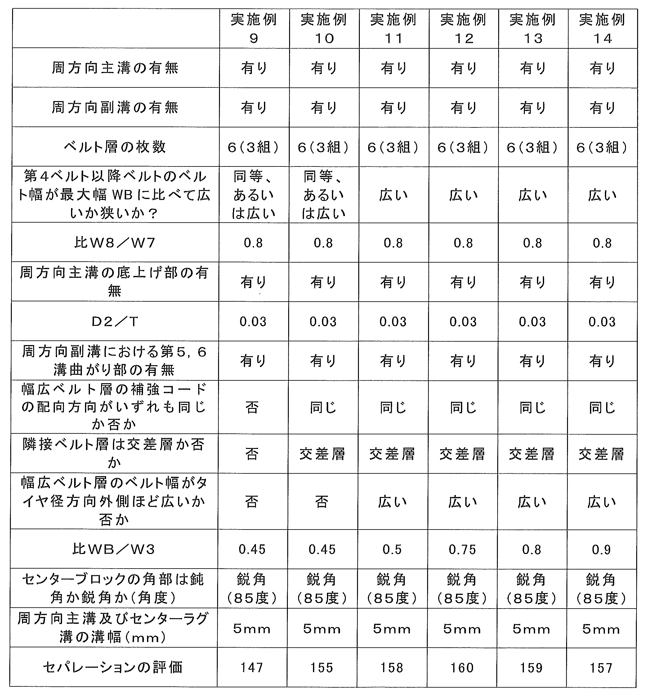
また、実施例8,9より、周方向副溝20に第5溝曲がり部21a及び第6溝曲がり部21bを設けることが、ベルトの層間セパレーションを抑える点から好ましいことがわかる。
さらに、実施例9,10より、複数のベルト対のうち、ベルト幅の広いベルトの補強コードの配向方向がいずれも同じであること、さらに、タイヤ径方向に隣接するベルトと交差層を成すこと(ベルトの補強コードの配向方向が、タイヤ周方向からタイヤ幅方向の異なる向きに向かって傾斜していること)が、ベルトの層間セパレーションを抑える点から好ましいことがわかる。
また、実施例11~14より、比WB/W3は0.5~0.8であり、ベルト幅W3がベルト幅W2より広いことが、ベルトの層間セパレーションを抑える点から好ましいことがわかる。
さらに、実施例15~19より、周方向主溝12及びセンターラグ溝14の溝幅は、7~20mmであることがベルトの層間セパレーションを抑える点から好ましいことがわかる。
以上より、本実施形態の効果は明らかである。
2 トレッド部
3 サイドウォール部
4 ビード部
4a ビードコア
5 カーカス層
6 ベルト部
6a 第1の交差ベルト層
6b 第2の交差ベルト層
6c 第3の交差ベルト層
10,110 ショルダーラグ溝
11a 第3溝曲がり部
11b 第4溝曲がり部
12,112 周方向主溝
12a 底上げ部
14,114 センターラグ溝
14a 第1溝曲がり部
14b 第2溝曲がり部
16,116 センターブロック
18 トレッド端
20 周方向副溝
21a 第5溝曲がり部
21b 第6溝曲がり部
61 第1ベルト
62 第2ベルト
63 第3ベルト
64 第4ベルト
65 第5ベルト
66 第6ベルト
Claims (18)
- トレッドパターン付き重荷重用空気入りタイヤであって、
前記トレッドパターンは、
タイヤ周方向に間隔をあけて複数設けられ、タイヤ赤道線を横切るようにタイヤ赤道線を基準としたタイヤ幅方向の第1の側及び第2の側の半トレッド領域に延びて両端を有するセンターラグ溝と、
複数の前記センターラグ溝のうちタイヤ周方向に隣接するセンターラグ溝の間のタイヤ周方向の位置に設けられるラグ溝であって、前記半トレッド領域のそれぞれにおいて、タイヤ幅方向外側に延びて、タイヤ幅方向外側の端がタイヤ幅方向の両側にある接地端に開口し、タイヤ幅方向内側の端のタイヤ幅方向の位置が、前記センターラグ溝の端のタイヤ幅方向の位置に比べてタイヤ幅方向外側にあるショルダーラグ溝と、
前記半トレッド領域のそれぞれにおいて、前記センターラグ溝の端と、前記ショルダーラグ溝のタイヤ幅方向の内側の端を交互に接続してタイヤ周上全周にわたって波形状に形成され、前記ショルダーラグ溝より溝幅が狭い一対の周方向主溝と、
前記センターラグ溝と前記一対の周方向主溝によって画されてタイヤ周方向に一列に複数形成されたセンターブロックと、
前記センターブロックの領域を分割するようにタイヤ赤道線に沿ってタイヤ周方向に延びる周方向副溝と、
を有し、
前記ベルト部は、
タイヤ径方向の最も内側に位置する第1ベルトからタイヤ径方向外側に向かって順番に、前記第1ベルトのベルト幅と異なるベルト幅を有する第2ベルト、第3ベルト、及び前記第3ベルトのベルト幅と異なるベルト幅を有する第4ベルトを少なくとも含み、前記第1ベルトと前記第2ベルト、及び前記第3ベルトと前記第4ベルトをそれぞれ対として、少なくとも2対以上を有する、ベルト層の積層構造を有し、
ベルト層の各対は、ベルト幅が広いベルト層のベルト幅W7に対する、ベルト幅が狭いベルト層のベルト幅W8の比W8/W7は、0.75以上0.90以下であり、
前記ベルト部の前記積層構造におけるタイヤ径方向最内側のベルトからタイヤ径方向外側向かって4番目以降のベルトのべルト幅は、いずれも、前記センターブロックのタイヤ幅方向の最大幅WBと同じか、最大幅WBに比べて広い、ことを特徴とする重荷重用空気入りタイヤ。 - 前記一対の周方向主溝それぞれにおいて、溝深さが部分的に浅くなった底上げ部を備える、請求項1に記載の重荷重用空気入りタイヤ。
- 前記底上げ部における溝深さをD2、前記トレッド部のタイヤ幅方向のトレッド幅をTとしたとき、D2/T<0.05である、請求項2に記載の重荷重用空気入りタイヤ。
- 前記周方向副溝は、タイヤ周方向に隣接するセンターラグ溝間の領域において、溝の延在方向を変える溝曲がり部を少なくとも2つ備える、請求項1~3のいずれか1項に記載の重荷重用空気入りタイヤ。
- 前記ベルト層の各対のうち、ベルト幅が広いベルト層の補強コードの配向方向は、いずれも、タイヤ周方向からタイヤ幅方向の同じ側に向かって傾斜した方向である、請求項1~4のいずれか1項に記載の重荷重用空気入りタイヤ。
- 前記ベルト部に含まれるベルトのうち隣接するいずれのベルト同士においても、ベルトの補強コードが、タイヤ周方向からタイヤ幅方向の異なる側に向かって傾斜した交差層である、請求項1~5のいずれか1項に記載の重荷重用空気入りタイヤ。
- 前記ベルト層の各対のうち、ベルト幅が広いベルト層のベルト幅に関して、タイヤ径方向外側に位置するベルト層ほど、ベルト幅が広い、請求項1~6のいずれか1項に記載の重荷重用空気入りタイヤ。
- 前記ベルト部は、タイヤ径方向の最も内側の第1の対、前記第1の対のタイヤ径方向外側に積層した第2の対、及び前記第2の対のタイヤ径方向外側に積層した第3の対を含み、
前記第3の対のうちベルト幅の狭いベルト層のベルト幅W3に対する、前記センターブロックのタイヤ幅方向の最大幅WBの比WB/W3は0.5以上0.8以下であり、ベルト幅W3は、前記第2の対のうちベルト幅の狭いベルト層のベルト幅W2より広い、請求項1~7のいずれか1項に記載の重荷重用空気入りタイヤ。 - 前記ベルト部は、タイヤ径方向の最も内側の第1の対、前記第1の対のタイヤ径方向外側に積層した第2の対、及び前記第2の対のタイヤ径方向外側に積層した第3の対を含み、
前記第1の対のうちベルト幅の狭いベルト層のベルト幅W1は、前記センターブロックのタイヤ幅方向の最大幅WBに比べて狭い、請求項1~8のいずれか1項に記載の重荷重用空気入りタイヤ。 - 前記周方向主溝に対応して前記センターブロックに角部が形成され、前記角部のなす角は、鈍角である、請求項1~9のいずれか1項に記載の重荷重用空気入りタイヤ。
- 前記周方向主溝の溝幅および前記センターラグ溝の溝幅は7mm以上20mm以下の範囲にある、請求項1~10のいずれか1項に記載の重荷重用空気入りタイヤ。
- 建設用車両または産業用車両に装着される、請求項1~11のいずれか1項に記載の重荷重用空気入りタイヤ。
- 前記センターラグ溝は、前記第1の側においてタイヤ周方向の第3の側に突出するように屈曲又は湾曲する第1溝曲がり部と、前記第2の側においてタイヤ周方向の前記第3の側の反対側である第4の側に突出するように屈曲又は湾曲する第2溝曲がり部と、を備え、
前記センターラグ溝が前記周方向主溝と接続する前記第1の側の第1接続端部及び前記第2の側の第2接続端部は、前記周方向主溝のタイヤ幅方向の内側の先端と接続し、前記センターラグ溝の前記第2接続端部は、前記第1接続端部よりもタイヤ周方向の第3の側にあり、
前記センターラグ溝の溝幅方向の中心位置に関し、前記第1接続端部と前記第1溝曲がり部がタイヤ周方向の前記第3の側に突出する突出端とを結ぶ第1直線のタイヤ幅方向に対する傾斜角度、および、前記第2接続端部と前記第2溝曲がり部がタイヤ周方向の前記第4の側に突出する突出端とを結ぶ第2直線のタイヤ幅方向に対する傾斜角度は、前記センターラグ溝の前記第1接続端部と前記第2接続端部を結ぶ第3直線のタイヤ幅方向に対する傾斜角度よりも大きい、請求項1~12のいずれか1項に記載の重荷重用空気入りタイヤ。 - 前記センターラグ溝の溝幅方向の中心位置に関し、前記第1溝曲がり部がタイヤ周方向の前記第3の側に突出する突出端と前記第1接続端部との間の前記センターラグ溝の部分は、前記第1直線上、あるいは前記第1直線に対して前記第3の側にあり、前記第2溝曲がり部がタイヤ周方向の前記第4の側に突出する突出端と前記第2接続端部との間の前記センターラグ溝の部分は、前記第2直線上、あるいは前記第2直線に対して前記第4の側にある、請求項13に記載の重荷重用空気入りタイヤ。
- 前記周方向副溝は、前記周方向主溝よりも溝深さが浅く、前記周方向副溝は、タイヤ赤道線に沿ってタイヤ周上全周にわたって形成され、
前記周方向副溝は、前記第1溝曲がり部と前記第2溝曲がり部を含む、前記第1溝曲がり部と前記第2溝曲がり部の間に挟まれたタイヤ幅方向の領域内で前記センターラグ溝を突き抜けて横切るように交差する、請求項13または14に記載の重荷重用空気入りタイヤ。 - 前記周方向副溝には、タイヤ周方向の前記第3の側にすすむとき、タイヤ径方向外側からタイヤ径方向内側に向かって前記トレッドパターンを見たとき、時計回転方向に向きを変えるように、湾曲あるいは屈曲した第5溝曲がり部と、反時計回転方向に向きを変えるように、湾曲あるいは屈曲した第6溝曲がり部がタイヤ周上に設けられ、前記センターラグ溝のうち隣接するセンターラグ溝間にある前記周方向副溝の部分は、前記第5溝曲がり部の1つと前記第6溝曲がり部の1つが配置されている、請求項15に記載の重荷重用空気入りタイヤ。
- 前記周方向副溝には、前記第5溝曲がり部および前記第6溝曲がり部のそれぞれがタイヤ周方向に沿って2つ連続して設けられ、連続して設けられる2つの第5溝曲がり部および2つの第6溝曲がり部のぞれぞれの間で、前記センターラグ溝が横切る、請求項16に記載の重荷重用空気入りタイヤ。
- 前記周方向副溝には、前記第5溝曲がり部の1つ、前記第5溝曲がり部の1つ、前記第6溝曲がり部の1つ、及び前記第6溝曲がり部の1つを、タイヤ周方向に沿って順番に配置した組を1組として、複数組がタイヤ周上に設けられ、
前記周方向副溝のうち、前記第5溝曲がり部の1つと前記第5溝曲がり部の1つの間の部分、及び前記第6溝曲がり部の1つと前記第6溝曲がり部の1つの間の部分は、タイヤ赤道線に平行に延びる直線溝である、請求項16または17に記載の重荷重用空気入りタイヤ。
Priority Applications (5)
| Application Number | Priority Date | Filing Date | Title |
|---|---|---|---|
| US15/523,326 US10029517B2 (en) | 2014-10-31 | 2015-10-19 | Heavy-duty pneumatic tire |
| CN201580040327.4A CN106573497B (zh) | 2014-10-31 | 2015-10-19 | 重载荷用充气轮胎 |
| JP2015551912A JP6229735B2 (ja) | 2014-10-31 | 2015-10-19 | 重荷重用空気入りタイヤ |
| RU2017112979A RU2633447C1 (ru) | 2014-10-31 | 2015-10-19 | Пневматическая шина для высоконагруженных машин |
| AU2015338175A AU2015338175B9 (en) | 2014-10-31 | 2015-10-19 | Heavy-duty pneumatic tire |
Applications Claiming Priority (4)
| Application Number | Priority Date | Filing Date | Title |
|---|---|---|---|
| JP2014222857 | 2014-10-31 | ||
| JP2014-222857 | 2014-10-31 | ||
| JPPCT/JP2015/063719 | 2015-05-13 | ||
| PCT/JP2015/063719 WO2016013276A1 (ja) | 2014-07-23 | 2015-05-13 | 重荷重用空気入りタイヤ |
Publications (1)
| Publication Number | Publication Date |
|---|---|
| WO2016067945A1 true WO2016067945A1 (ja) | 2016-05-06 |
Family
ID=55857286
Family Applications (1)
| Application Number | Title | Priority Date | Filing Date |
|---|---|---|---|
| PCT/JP2015/079409 Ceased WO2016067945A1 (ja) | 2014-10-31 | 2015-10-19 | 重荷重用空気入りタイヤ |
Country Status (6)
| Country | Link |
|---|---|
| US (1) | US10029517B2 (ja) |
| JP (1) | JP6229735B2 (ja) |
| CN (1) | CN106573497B (ja) |
| AU (1) | AU2015338175B9 (ja) |
| RU (1) | RU2633447C1 (ja) |
| WO (1) | WO2016067945A1 (ja) |
Cited By (2)
| Publication number | Priority date | Publication date | Assignee | Title |
|---|---|---|---|---|
| WO2018235345A1 (ja) * | 2017-06-22 | 2018-12-27 | 株式会社ブリヂストン | 重荷重用タイヤ |
| JP2022059374A (ja) * | 2020-10-01 | 2022-04-13 | Toyo Tire株式会社 | 空気入りタイヤ |
Families Citing this family (7)
| Publication number | Priority date | Publication date | Assignee | Title |
|---|---|---|---|---|
| JP6229727B2 (ja) * | 2014-07-23 | 2017-11-15 | 横浜ゴム株式会社 | 重荷重用空気入りタイヤ |
| WO2016059992A1 (ja) * | 2014-10-16 | 2016-04-21 | 横浜ゴム株式会社 | 空気入りタイヤ |
| WO2016063713A1 (ja) * | 2014-10-20 | 2016-04-28 | 横浜ゴム株式会社 | 空気入りタイヤ |
| JP6523094B2 (ja) * | 2015-07-29 | 2019-05-29 | Toyo Tire株式会社 | 空気入りタイヤ |
| FR3050402A1 (fr) * | 2016-04-22 | 2017-10-27 | Michelin & Cie | Bande de roulement de pneu comprenant des decoupures de differentes profondeurs |
| JP7199311B2 (ja) * | 2019-06-19 | 2023-01-05 | 株式会社ブリヂストン | 空気入りタイヤ |
| USD1118472S1 (en) | 2024-10-09 | 2026-03-17 | Mark Thornburg | Tire |
Citations (5)
| Publication number | Priority date | Publication date | Assignee | Title |
|---|---|---|---|---|
| JP2004075056A (ja) * | 2002-07-31 | 2004-03-11 | Bridgestone Corp | オフザロードタイヤ |
| WO2006001202A1 (ja) * | 2004-06-23 | 2006-01-05 | Bridgestone Corporation | 空気入りタイヤ |
| JP2006151083A (ja) * | 2004-11-26 | 2006-06-15 | Bridgestone Corp | 重荷重車両用タイヤ |
| JP2007191093A (ja) * | 2006-01-20 | 2007-08-02 | Bridgestone Corp | 建設車両用タイヤ |
| JP2008279976A (ja) * | 2007-05-14 | 2008-11-20 | Bridgestone Corp | 建設車両用重荷重空気入りラジアルタイヤ |
Family Cites Families (11)
| Publication number | Priority date | Publication date | Assignee | Title |
|---|---|---|---|---|
| JPH01156104A (ja) * | 1987-12-15 | 1989-06-19 | Bridgestone Corp | 高耐久性空気入りラジアルタイヤ |
| JP3569056B2 (ja) | 1995-11-15 | 2004-09-22 | 株式会社ブリヂストン | 空気入りタイヤ |
| JP3833785B2 (ja) * | 1997-07-15 | 2006-10-18 | 株式会社ブリヂストン | 空気入りタイヤ |
| JP2002067624A (ja) * | 2000-08-25 | 2002-03-08 | Sumitomo Rubber Ind Ltd | 空気入りタイヤ |
| USD457128S1 (en) * | 2001-02-20 | 2002-05-14 | The Goodyear Tire & Rubber Company | Tire tread |
| JP4149219B2 (ja) * | 2002-09-11 | 2008-09-10 | 株式会社ブリヂストン | 重荷重用タイヤ |
| JP4256173B2 (ja) * | 2003-01-21 | 2009-04-22 | 住友ゴム工業株式会社 | 重荷重用ラジアルタイヤ |
| JP4330561B2 (ja) * | 2005-07-12 | 2009-09-16 | 住友ゴム工業株式会社 | 重荷重用タイヤ |
| JP4570526B2 (ja) * | 2005-07-20 | 2010-10-27 | 株式会社ブリヂストン | 重荷重用空気入りタイヤ |
| JP5327944B2 (ja) * | 2007-05-17 | 2013-10-30 | 株式会社ブリヂストン | 空気入りラジアルタイヤ |
| JP5254760B2 (ja) * | 2008-11-27 | 2013-08-07 | 株式会社ブリヂストン | タイヤ |
-
2015
- 2015-10-19 JP JP2015551912A patent/JP6229735B2/ja active Active
- 2015-10-19 CN CN201580040327.4A patent/CN106573497B/zh active Active
- 2015-10-19 AU AU2015338175A patent/AU2015338175B9/en active Active
- 2015-10-19 RU RU2017112979A patent/RU2633447C1/ru active
- 2015-10-19 WO PCT/JP2015/079409 patent/WO2016067945A1/ja not_active Ceased
- 2015-10-19 US US15/523,326 patent/US10029517B2/en active Active
Patent Citations (5)
| Publication number | Priority date | Publication date | Assignee | Title |
|---|---|---|---|---|
| JP2004075056A (ja) * | 2002-07-31 | 2004-03-11 | Bridgestone Corp | オフザロードタイヤ |
| WO2006001202A1 (ja) * | 2004-06-23 | 2006-01-05 | Bridgestone Corporation | 空気入りタイヤ |
| JP2006151083A (ja) * | 2004-11-26 | 2006-06-15 | Bridgestone Corp | 重荷重車両用タイヤ |
| JP2007191093A (ja) * | 2006-01-20 | 2007-08-02 | Bridgestone Corp | 建設車両用タイヤ |
| JP2008279976A (ja) * | 2007-05-14 | 2008-11-20 | Bridgestone Corp | 建設車両用重荷重空気入りラジアルタイヤ |
Cited By (4)
| Publication number | Priority date | Publication date | Assignee | Title |
|---|---|---|---|---|
| WO2018235345A1 (ja) * | 2017-06-22 | 2018-12-27 | 株式会社ブリヂストン | 重荷重用タイヤ |
| JPWO2018235345A1 (ja) * | 2017-06-22 | 2020-06-18 | 株式会社ブリヂストン | 重荷重用タイヤ |
| JP2022059374A (ja) * | 2020-10-01 | 2022-04-13 | Toyo Tire株式会社 | 空気入りタイヤ |
| JP7634953B2 (ja) | 2020-10-01 | 2025-02-25 | Toyo Tire株式会社 | 空気入りタイヤ |
Also Published As
| Publication number | Publication date |
|---|---|
| JP6229735B2 (ja) | 2017-11-15 |
| US20170240000A1 (en) | 2017-08-24 |
| CN106573497B (zh) | 2018-05-15 |
| AU2015338175B2 (en) | 2017-11-02 |
| AU2015338175A1 (en) | 2017-06-08 |
| AU2015338175B9 (en) | 2017-11-09 |
| RU2633447C1 (ru) | 2017-10-12 |
| JPWO2016067945A1 (ja) | 2017-08-10 |
| US10029517B2 (en) | 2018-07-24 |
| CN106573497A (zh) | 2017-04-19 |
Similar Documents
| Publication | Publication Date | Title |
|---|---|---|
| JP6229735B2 (ja) | 重荷重用空気入りタイヤ | |
| JP6229727B2 (ja) | 重荷重用空気入りタイヤ | |
| JP6229722B2 (ja) | 重荷重用空気入りタイヤ | |
| JP6432518B2 (ja) | 空気入りタイヤ | |
| CN106536227A (zh) | 充气轮胎 | |
| JP6229723B2 (ja) | 重荷重用空気入りタイヤ | |
| JP6229724B2 (ja) | 重荷重用空気入りタイヤ | |
| JP6229734B2 (ja) | 空気入りタイヤ | |
| JP5910795B1 (ja) | 重荷重用空気入りタイヤ |
Legal Events
| Date | Code | Title | Description |
|---|---|---|---|
| ENP | Entry into the national phase |
Ref document number: 2015551912 Country of ref document: JP Kind code of ref document: A |
|
| 121 | Ep: the epo has been informed by wipo that ep was designated in this application |
Ref document number: 15853717 Country of ref document: EP Kind code of ref document: A1 |
|
| WWE | Wipo information: entry into national phase |
Ref document number: 15523326 Country of ref document: US |
|
| NENP | Non-entry into the national phase |
Ref country code: DE |
|
| ENP | Entry into the national phase |
Ref document number: 2017112979 Country of ref document: RU Kind code of ref document: A |
|
| ENP | Entry into the national phase |
Ref document number: 2015338175 Country of ref document: AU Date of ref document: 20151019 Kind code of ref document: A |
|
| 122 | Ep: pct application non-entry in european phase |
Ref document number: 15853717 Country of ref document: EP Kind code of ref document: A1 |