WO2016067729A1 - 画像生成装置、画像生成方法および較正方法 - Google Patents
画像生成装置、画像生成方法および較正方法 Download PDFInfo
- Publication number
- WO2016067729A1 WO2016067729A1 PCT/JP2015/074010 JP2015074010W WO2016067729A1 WO 2016067729 A1 WO2016067729 A1 WO 2016067729A1 JP 2015074010 W JP2015074010 W JP 2015074010W WO 2016067729 A1 WO2016067729 A1 WO 2016067729A1
- Authority
- WO
- WIPO (PCT)
- Prior art keywords
- head
- marker
- viewpoint position
- user
- markers
- Prior art date
Links
Images


Classifications
-
- H—ELECTRICITY
- H04—ELECTRIC COMMUNICATION TECHNIQUE
- H04N—PICTORIAL COMMUNICATION, e.g. TELEVISION
- H04N13/00—Stereoscopic video systems; Multi-view video systems; Details thereof
- H04N13/30—Image reproducers
- H04N13/327—Calibration thereof
-
- G—PHYSICS
- G06—COMPUTING; CALCULATING OR COUNTING
- G06T—IMAGE DATA PROCESSING OR GENERATION, IN GENERAL
- G06T7/00—Image analysis
- G06T7/70—Determining position or orientation of objects or cameras
-
- H—ELECTRICITY
- H04—ELECTRIC COMMUNICATION TECHNIQUE
- H04N—PICTORIAL COMMUNICATION, e.g. TELEVISION
- H04N13/00—Stereoscopic video systems; Multi-view video systems; Details thereof
- H04N13/10—Processing, recording or transmission of stereoscopic or multi-view image signals
- H04N13/106—Processing image signals
- H04N13/111—Transformation of image signals corresponding to virtual viewpoints, e.g. spatial image interpolation
- H04N13/117—Transformation of image signals corresponding to virtual viewpoints, e.g. spatial image interpolation the virtual viewpoint locations being selected by the viewers or determined by viewer tracking
-
- H—ELECTRICITY
- H04—ELECTRIC COMMUNICATION TECHNIQUE
- H04N—PICTORIAL COMMUNICATION, e.g. TELEVISION
- H04N13/00—Stereoscopic video systems; Multi-view video systems; Details thereof
- H04N13/30—Image reproducers
- H04N13/302—Image reproducers for viewing without the aid of special glasses, i.e. using autostereoscopic displays
-
- H—ELECTRICITY
- H04—ELECTRIC COMMUNICATION TECHNIQUE
- H04N—PICTORIAL COMMUNICATION, e.g. TELEVISION
- H04N13/00—Stereoscopic video systems; Multi-view video systems; Details thereof
- H04N13/30—Image reproducers
- H04N13/366—Image reproducers using viewer tracking
-
- G—PHYSICS
- G06—COMPUTING; CALCULATING OR COUNTING
- G06T—IMAGE DATA PROCESSING OR GENERATION, IN GENERAL
- G06T2207/00—Indexing scheme for image analysis or image enhancement
- G06T2207/30—Subject of image; Context of image processing
- G06T2207/30204—Marker
- G06T2207/30208—Marker matrix
Definitions
- the present invention relates to an image generation apparatus that generates a stereoscopic image, an image generation method, and a calibration method.
- Three-dimensional display devices such as a three-dimensional television and a head mounted display capable of presenting images in three dimensions are used.
- Devices capable of presenting images in three dimensions in portable terminals such as mobile phones and portable game machines have also been developed, and opportunities for general users to view stereoscopic images are increasing.
- a three-dimensional display device that displays a stereoscopic image enables the user to stereoscopically view an image by showing an image with parallax to the user's left and right eyes.
- the present invention has been made in view of these problems, and an object thereof is to provide an image generating apparatus, an image generating method, and a calibration method capable of generating a stable stereoscopic image even when the viewpoint is displaced. .
- an image generating apparatus scans a plurality of photographed images of a plurality of markers of a jewellery attached to the head of a user and generates a two-dimensional image of the plurality of markers on the photographed images.
- a marker detection unit that detects coordinates; and a viewpoint position correction unit that corrects a user's viewpoint position using two-dimensional coordinates of the detected plurality of markers without using the Z-direction coordinates of the markers;
- a stereoscopic image generation unit that generates a parallax image when a three-dimensional object is viewed from the viewpoint position.
- Another aspect of the invention is a calibration method.
- This method comprises a marker detection step of scanning a plurality of photographed images of a plurality of markers of the accessory attached to the head of the user to detect two-dimensional coordinates on the photographed images of the plurality of markers; A viewpoint position correction step of correcting the user's viewpoint position using the detected two-dimensional coordinates of the plurality of markers without using the parallax, and a parallax when the calibration three-dimensional object is viewed from the corrected viewpoint position
- the position of the marker is adjusted by moving the accessory mounted on the head of the user back and forth so that the three-dimensional image generation step of generating an image and the calibration three-dimensional object which is stereoscopically viewed becomes stationary even if the head is moved.
- a calibration step prompting the user.
- Yet another aspect of the present invention is an image generation method.
- This method comprises a marker detection step of scanning a plurality of photographed images of a plurality of markers of the accessory attached to the head of the user to detect two-dimensional coordinates on the photographed images of the plurality of markers; A viewpoint position correction step of correcting the user's viewpoint position using the detected two-dimensional coordinates of the plurality of markers without using the parallax image, and a parallax image when the three-dimensional object is viewed from the corrected viewpoint position And generating a stereoscopic image.
- stable stereoscopic video can be displayed even if the viewpoint is displaced.
- FIG.2 (a) and FIG.2 (b) are figures explaining the hair band with a marker which a user wears
- FIG. 5 (a) is a view for explaining the positional relationship between the three markers of the hair band and the camera
- FIG. 5 (b) is an image of the left head marker taken by the camera and an image of the right head marker.
- FIG. It is a function block diagram of the three-dimensional-image production
- FIGS. 9A and 9B are diagrams for explaining a method in which the marker detection unit scans the photographed image to detect the parietal marker, the left head marker, and the right head marker. It is a figure explaining the view frustum of the eye on either side at the time of carrying out the stereo display of a three-dimensional object on a screen. It is a figure explaining the translational correction amount of a viewpoint position when a viewpoint translates.
- FIGS. 9A and 9B are diagrams for explaining a method in which the marker detection unit scans the photographed image to detect the parietal marker, the left head marker, and the right head marker. It is a figure explaining the view frustum of the eye on either side at the time of carrying out the stereo display of a three-dimensional object on a screen. It is a figure explaining the translational correction amount of a viewpoint position when a viewpoint translates.
- FIGS. 9A and 9B are diagrams for explaining a method in which the marker detection unit scans the photographed image to detect the pari
- FIG. 12 (a) and 12 (b) are diagrams for explaining the change in the position of the top marker according to the tilt angle of the head.
- FIG. 13A and FIG. 13B are diagrams for explaining the displacement of the center of the eyepiece when the user tilts the head. It is a figure explaining the relationship between the mounting
- FIG. 15A and FIG. 15B are diagrams for explaining the advantage of not performing the correction of the viewpoint position in the Z direction.
- FIG. 7 is a diagram for explaining the positional relationship between a truncated pyramid, a three-dimensional object, and a screen when viewed from directly above the head of the user.
- FIG. 1 is a diagram for explaining a three-dimensional display device.
- the three-dimensional display device includes a game console 200, a display 300, and a camera 310.
- the display 300 is connected to the game console 200 via an interface that connects peripheral devices such as wireless communication or USB.
- the game console 200 may be further connected to a server via a network.
- the display 300 may be connected to a computer or a portable terminal instead of the game console 200.
- the camera 310 is installed at an upper portion of the display 300 or the like, photographs a user looking at the display 300, and supplies the photographed image to the game machine 200.
- FIG. 2A and FIG. 2B are diagrams for explaining the marker-equipped hair band 100 worn by the user.
- FIG. 2A is a configuration diagram of the hair band 100 with a marker.
- the hair band 100 has a parietal marker 110T, a left head marker 110L, and a right head marker 110R.
- the top marker 110T is provided on the head of the user
- the left head marker 110L and the right head marker 110R are provided on the left and right sides of the user.
- FIG. 2B shows the user wearing the marker-equipped hair band 100.
- These markers are, as an example, infrared light emitting diodes.
- the marker is mounted on the hair band, but any head accessory can be used without being limited to the hair band as long as it can be mounted on the head of the user and the mounting position can be adjusted back and forth.
- any head accessory can be used without being limited to the hair band as long as it can be mounted on the head of the user and the mounting position can be adjusted back and forth.
- it may be a headset or a hat.
- FIG. 3 is a view for explaining a user wearing the marker-equipped hair band 100 looking at the display 300.
- the user observes the display 300 from a position separated by a distance d from the display 300.
- the user wears the stereoscopic glasses 400 and looks at the screen of the display 300 on which parallax images are displayed.
- a camera 310 installed at the top of the display 300 captures the head of the user wearing the markered hair band 100.
- the camera 310 includes an infrared transmission filter, and performs image processing for detecting a bright spot from the image of the user's head taken by the camera 310, whereby the hair band 100 head marker 110T, the left head marker 110L, and The position of the right temporal marker 110R can be detected.
- FIG. 4 is a view showing how the camera 310 detects the light emission distribution of the marker 110.
- light emitting diodes directed to the light emission distribution are used, but detection of the position when the camera 310 images the light of the marker 110 to detect the position of the marker 110 The accuracy will depend on the emission distribution.
- the light emission intensity distribution of the infrared light emitting diode spreads in the front direction as indicated by the reference numeral 112.
- the light emission distribution is substantially symmetrical when viewed from the front of the light emitting diode and there are few sharp changes. The intensity distribution of is observed.
- the camera 310 captures the light 116 from the front of the light emitting diode, the center of gravity of the area of the portion filled with the code 114 is detected as the position of the marker 110, and the position of the marker 110 can be detected with high accuracy.
- the camera 310 catches the light 118 from the oblique direction of the light emitting diode, the amount of light is extremely small, and the angle becomes uneven due to the angle, so the measurement accuracy of the center of gravity position drops sharply. Is difficult to detect accurately.
- FIG. 5A is a view for explaining the positional relationship between the three markers 110T, 110L and 110R of the hair band 100 and the camera 310.
- FIG. Since the parietal marker 110T is in a position directly facing the camera 310, the camera 310 can capture an image of the parietal marker 110T and measure two-dimensional coordinates of the parietal marker 110T with high accuracy. On the other hand, since the left head marker 110L and the right head marker 110R are positioned obliquely as viewed from the camera 310, the measurement accuracy of the two-dimensional coordinates is lowered.
- FIG. 5B is a view showing an image 510L of the left head marker 110L taken by the camera 310 and an image 510R of the right head marker 110R.
- a measurement error 512L exists in a two-dimensional coordinate of the image 510L of the left head marker 110L
- a measurement error 512R exists in a two-dimensional coordinate of the image 510R of the right head marker 110R
- the measurement accuracy is low.
- the horizontal error is a problem when detecting the tilt of the head. In the measurement of the tilt angle vAngle of the head, the influence of the error can be minimized.
- the correction amount of the viewpoint position is determined on the basis of the two-dimensional coordinates of the parietal marker 110T.
- the user moves the position of the hair band 100 back and forth to adjust the position of the parietal marker 110T so that correction of the viewpoint position can be appropriately made.
- individual differences can be minimized, and correction processing of the viewpoint position in stereo display can be realized with a very small amount of calculation.
- the inclination of the head is detected from the two-dimensional coordinates of the left head marker 110L and the right head marker 110R to perform additional stereo display correction.
- the coordinates in the Z direction of the parietal marker 110T, the left head marker 110L and the right head marker 110R are not used.
- By using only two-dimensional coordinates, ie, the position of the head in the XY plane from the parietal marker 110T, and only the tilt angle of the head from the left head marker 110L and the right head marker 110R, and using them for correction calculation It is possible to realize stable viewpoint position correction processing with little influence of measurement error.
- the left head marker 110L and the right head marker 110R are placed on the hair band 100 at an angle so as to face the front direction of the camera 310, the left head marker 110L and the right head marker 110R are also two-dimensional. Among the coordinates, it is possible to increase the measurement accuracy in the horizontal direction, but this is not a very realistic solution as it is effective only when the distance from the camera 310 to the hair band 100 is constant. In the present embodiment, of the two-dimensional coordinates of the left head marker 110L and the right head marker 110R, it is assumed that the measurement accuracy in the horizontal direction is low, and the left head marker is not affected by the measurement error.
- the angle formed by the line connecting the left head marker 110L and the right head marker 110R with respect to the horizontal direction (that is, the user does not directly use detected two-dimensional coordinates for 110L and right head marker 110R).
- FIG. 6 is a functional configuration diagram of a stereoscopic image generation device 210 according to the present embodiment.
- the figure depicts a block diagram focusing on functions, and these functional blocks can be realized in various forms by hardware only, software only, or a combination thereof.
- the stereoscopic image generating device 210 is mounted on the game machine 200 connected to the display 300, at least a part of the functions of the stereoscopic image generating device 210 may be mounted on the control unit of the display 300. Alternatively, at least a part of the functions of the three-dimensional image generation apparatus 210 may be implemented on a server connected to the game console 200 via a network.
- the photographing unit 10 stores, in a memory, a photographed image of the head of the user wearing the marker-equipped hair band 100 photographed by the camera 310.
- the marker detection unit 20 scans the captured image to detect two-dimensional coordinates of the parietal marker 110T, the left head marker 110L, and the right head marker 110R, and supplies the two-dimensional coordinates to the viewpoint position correction unit 30.
- the viewpoint position correction unit 30 corrects the viewpoint position based on the two-dimensional coordinates of the head top marker 110T, the left head marker 110L, and the right head marker 110R acquired from the marker detection unit 20, and the updated viewpoint position The above information is given to the three-dimensional image generation unit 40.
- the viewpoint position correction unit 30 corrects the viewpoint position without using the coordinate in the Z direction of each of the markers 110T, 110L, and 110R, that is, the depth information.
- the three-dimensional image generation unit 40 reads a three-dimensional model of an object to be displayed from the three-dimensional model storage unit 50, and an image for the left eye having parallax when viewed from the updated viewpoint position given from the viewpoint position correction unit 30. And an image for the right eye are generated and supplied to the display unit 60.
- the display unit 60 displays the image for the left eye and the image for the right eye on the display 300.
- the calibration (calibration) unit 70 instructs the stereoscopic image generation unit 40 to generate a three-dimensional object for calibration.
- the calibration unit 70 also adjusts the mounting position of the marker-equipped hair band 100 and displays on the display 300 a message prompting the user to search for a mounting position at which the three-dimensional object for calibration does not move even if the head is moved.
- the display unit 60 is instructed to do this.
- the display unit 60 displays a parallax image of the three-dimensional object for calibration on the display 300, and also displays on the display 300 a message prompting the user to adjust the mounting position of the hair band 100 with a marker. This message may be provided to the user by voice.
- FIG. 7 is a detailed functional block diagram of the viewpoint position correction unit 30.
- the parietal marker coordinate acquisition unit 72, the left head marker coordinate acquisition unit 74, and the right head marker coordinate acquisition unit 76 are respectively provided from the marker detection unit 20 for the parietal marker 110T, the left head marker 110L, and the right head marker 110R. Get coordinate position.
- the translational movement calculation unit 78 detects the translational movement of the user's viewpoint using the two-dimensional coordinates of the parietal marker 110T.
- the head tilt calculation unit 80 calculates the tilt angle of the user's head using two-dimensional coordinates of the left head marker 110L and the right head marker 110R, and the translation correction amount calculator 82 and the shift amount calculator 84. Give to.
- the translational correction amount calculation unit 82 calculates the translational correction amount of the viewpoint position from the translational movement of the viewpoint of the user and the inclination angle of the head of the user, and supplies the translation correction amount to the viewpoint position update unit 86.
- the shift amount calculation unit 84 calculates the shift amount of the viewpoint position according to the inclination of the head of the user using the inclination angle of the head of the user, and supplies the shift amount to the viewpoint position update unit 86.
- the viewpoint position updating unit 86 updates the viewpoint position using the translational correction amount and shift amount of the viewpoint position, and supplies the information of the updated viewpoint position to the stereoscopic image generating unit 40.
- FIG. 8 is a diagram showing a parietal marker 110T, a left head marker 110L, and a right head marker 110R in an image 500 captured by the camera 310.
- the photographed image 500 is an image of W horizontal pixels and H vertical pixels.
- the marker detection unit 20 sets the upper left of the captured image 500 as (0, 0), the two-dimensional coordinates (wposT, hposT) of the parietal marker 110T, the two-dimensional coordinates (wposL, hposL) of the left head marker 110L, the right head
- the two-dimensional coordinates (wposR, hposR) of the partial marker 110R are determined in pixel units.
- FIGS. 9A and 9B are diagrams for explaining a method in which the marker detection unit 20 scans the captured image 500 to detect the parietal marker 110T, the left head marker 110L, and the right head marker 110R. It is.
- FIG. 9A scanning is performed line by line from the upper left of the captured image 500 to detect the parietal marker 110T.
- the photographed image 500 is divided into right and left at the position of the parietal marker 110T, and from above in the left area Scan every line to detect the two-dimensional coordinates (wposR, hposR) of the right head marker 110R, scan each line from the top in the right area, and then two-dimensional coordinates (wposL, hposL) of the left head marker 110L ) To detect.
- FIG. 10 is a view for explaining the left and right eye frustums 630L and 630R when the three-dimensional object 600 is displayed on the screen 610 in stereo.
- Camera Input Coordinate System This is a two-dimensional coordinate system of a captured image by the camera 310, and the unit of the coordinate system is a pixel unit of the captured image.
- World Coordinate System This is a coordinate system of a three-dimensional space in which the three-dimensional object 600 exists. The midpoint between the origin of the perspective projection of the right eye and the origin of the perspective projection of the left eye is the origin of the world coordinate system, the direction toward the screen of the display 300 is the Z axis, the horizontal direction is the X axis, and the vertical direction is the Y axis. The unit of coordinate system is the unit of length of real space.
- Display Screen Coordinate System This is a two-dimensional screen coordinate system represented by the pixel space of the display 300, and the unit of the coordinate system is the display pixel unit of the display 300.
- the stereo display sees the three-dimensional object 600 using the viewing frustums 630L and 630R parallel-shifted by -Ew / 2 for the left eye and Ew / 2 for the left eye, where Ew is the distance between human left eye 620L and right eye 620R. It does by projecting. Although it is considered that the actual eyeball position is before the origins 640L and 640R of the sights 630L and 630R, here, for simplicity, the positions of the origins 640L and 640R of the sights 630L and 630R I am drawing an eyeball.
- the image is moved in the opposite direction in the screen coordinate system by an amount corresponding to the above.
- the distance from the screen to the viewpoint is a fixed set value. Although it is possible to measure the Z coordinate (depth) of the user's viewpoint by the camera 310, since the instability of the display image is increased due to extra calculation processing, the Z coordinate is not measured here, and the viewpoint position in the Z direction Do not make corrections. Since the viewpoint position is corrected using only the two-dimensional coordinates (X, Y) of the marker on the captured image without using the Z coordinate, the influence of the error can be minimized.
- FIG. 11 is a diagram for explaining a translational correction amount of the viewpoint position when the viewpoint is translated.
- a view frustum 630L 'of the left eye 620L' and a view frustum 630R 'of the right eye 620R' when the viewpoint is translated by xTran in the X axis (horizontal direction) are illustrated.
- the translational movement calculation unit 78 calculates the correction amount (xTran, yTran) of the display position of the three-dimensional object 600 in the world coordinate system from the position (wposT, hposT) of the top marker 110T of the camera input coordinate system as follows. . In this calculation, it is assumed that the user's eyes are kept horizontal.
- xTran -(wposT-wRef) wScale
- yTran (hposT-hRef) ⁇ hScale
- wRef, hRef is a reference point at the center of the camera input coordinate system.
- wRef may be the X coordinate of the center position of the left and right truncated cones of the camera input coordinate system.
- hRef may be the Y coordinate of the position of the parietal marker 110T detected by the camera 310.
- WScale and hScale are scaling factors for converting the pixel position of the marker obtained on the camera input coordinate system into the world space coordinate system. Although it is originally a function with the distance from the camera to the marker as a variable, in the case of this method, processing is performed with a constant in order to assume that the user performs viewing near the optimum position on the display 300.
- the inclination of the head of the user in the world coordinate system from the relationship between the two-dimensional coordinates (wposL, hposL) of the left head marker 110L in the camera input coordinate system and the two-dimensional coordinates (wposR, hposR) of the right head marker 110R. Measure Also in this case, the inclination in the Z direction in the world coordinate system is ignored, and the inclination in a two-dimensional plane parallel to the camera coordinate system and the screen coordinate system is handled. Let this angle of inclination be vAngle. vAngle is calculated by the following formula.
- VAngle arcTan ((hposR-hposL) / (wposR-wposL))
- the translational correction amount calculation unit 82 further corrects the translational correction amounts xTran and yTran obtained assuming that there is no head tilt using the head tilt angle vAngle as follows.
- hDist is a distance between the position of the top marker 110T on the camera input coordinate system and the reference position of the user's eyes (the origin of the world coordinate system).
- FIGS. 12 (a) and 12 (b) are diagrams for explaining changes in the position of the parietal marker 110T due to the inclination angle vAngle of the head.
- FIG. 12A shows the position of the top marker 110T when the user's eyes are horizontal, and the top marker 110T is separated from the center of the user's eyes by hDist.
- FIG. 12 (b) shows the position of the top marker 110T when the user's eyes are inclined at an angle vAngle with respect to the horizontal direction, and the top marker 110T is hDist ⁇ sin (horizontal axis (X axis)) It is displaced in the vertical direction (Y axis) by hDist ⁇ (1-cos (vAngle)) by vAngle).
- the translational correction amounts xTran and yTran are corrected as in the above equation.
- the translational correction amounts xTran and yTran thus obtained taking into consideration the inclination of the head are perspectives for stereoscopic vision based on changes in two-dimensional coordinates of the three markers 110T, 110L and 110R in the camera input coordinate system.
- the value is an estimate of how far the center of the projection frustum deviates from the origin of the world coordinate system.
- FIG. 11 shows the movement of the truncated pyramid when only the horizontal direction is considered, the same applies to the vertical direction.
- this movement moves the actual three-dimensional object 600 by -xTran, -yTran in the world coordinate system, and further moves the generated image by an amount corresponding to xTran, yTran in the screen space. It is obtained by
- the correction amount xAdj, yAdj for each pixel on the screen space is expressed by the following equation.
- xAdj -xTran / sScale
- yAdj -yTran / sScale
- sScale is a coordinate conversion coefficient from the world coordinate system to the screen coordinate system.
- the ratios differ in the X direction and the Y direction, it is necessary to use values in accordance with each.
- the center of the cone is offset from the origin of the world coordinate system. If the left and right parallax images are displayed on the display 300 without correcting the viewpoint position with respect to this deviation, the stereoscopic image appears to shake according to the translational motion or rotational motion of the user's head, resulting in intoxication.
- the translational correction amounts xTran and yTran are determined, the viewpoint position is updated, and left and right parallax images when viewed from the updated viewpoint position are generated and displayed on the display 300.
- FIG. 13A and FIG. 13B are diagrams for explaining the displacement of the center of the eyepiece when the user tilts the head.
- each of the fluoroscopic pedestals 630L and 630R is translated by Ew / 2 each It suffices to generate a binocular image that is
- the shift amount calculation unit 84 is a left head marker 110L, using the inclination vAngle of the user's eyes obtained from the right head marker 110R, shift correction is performed on the amount of parallel movement of the eyepiece.
- This correction is expressed as shift correction amounts xshift and yshift of the positions of the left and right eyes on the world coordinate system by the following equation.
- About the right eye x Shift -(Ew / 2) ⁇ cos (vAngle)
- y Shift (Ew / 2) ⁇ sin (vAngle)
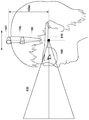
- FIG. 14 is a view for explaining the relationship between the mounting position of the hair band 100 with a marker and the projection origin of the truncated pyramid.
- the projection origin 640 of the truncated pyramid is considered to be the focal position of the human eye, and to be behind the actual eye position.
- the projection origin 640 of the frustum is exactly the middle point of the projection origin of each frustum because there are two right and left frustums, but here, it is simple Therefore, it is referred to as the projection origin of the truncated pyramid.
- the image is corrected using the projection origin 640 of the viewing platform as the origin of the world coordinate system.
- the top marker 110T of the hair band 100 which is used as a reference for detecting the viewpoint position, is located at the origin of the world coordinate system, that is, hDist directly above the projection origin 640 of the truncated pyramid. It will be.
- the projection origin of the truncated pyramid is the focal position of the human eye, the position can not usually be measured directly. Therefore, markers such as the hair band 100 are attached to the head and the mounting position can be adjusted back and forth by incorporating a marker into the accessory so that the user can naturally see the stereoscopic image projected on the screen. By making adjustments, it is possible to set the projection origin of an ideal truncated pyramid tailored to each person.
- the calibration unit 70 instructs the stereoscopic image generation unit 40 and the display unit 60 to generate a parallax image of a calibration three-dimensional object and to display the parallax image on the display 300.
- the calibration unit 70 instructs the user to adjust the mounting position of the hair band 100 with a marker back and forth by means of characters or voice on the screen.
- the user moves the head of the head to the left or right while rotating the head while looking at the parallax image of the calibration three-dimensional object displayed on the display 300 through the stereoscopic glasses 400, and the calibration three-dimensional object moves.
- the mounting position of the hair band 100 is adjusted back and forth so as not to occur.
- the hair band 100 top marker 110T is positioned directly above the projection origin 640 of the user's frustum, the correction algorithm of the viewpoint position works effectively, and even if the head is moved, 3 for calibration.
- Dimension objects stop moving.
- the calibration is completed, and the calibration unit 70 instructs the stereoscopic image generation unit 40 and the display unit 60 to end the generation and display of parallax images of a three-dimensional object for calibration.
- a marker may be attached to the surface of the stereoscopic glasses 400 and photographed by a camera, and the position of the marker may be three-dimensionally measured to calculate the projection origin of the truncated pyramid.
- the position of the marker may be three-dimensionally measured to calculate the projection origin of the truncated pyramid.
- the position of the marker may be three-dimensionally measured to calculate the projection origin of the truncated pyramid.
- it is offset in the Z direction from the projection origin of the truncated pyramid, so accurate information in the depth direction is necessary to obtain the projection origin of the projection pedestal from the position of the marker. It will be necessary and the calculation will be complicated.
- since it is difficult to distinguish between rotation and translation of the user's head even when the marker of the stereoscopic glasses 400 is photographed an error is likely to occur in position measurement.
- the parietal marker 110T is adjusted right above the projection origin of the frustum, the projection origin of the parietal marker 110T marker and the frustum does not deviate in the Z direction.
- the correction calculation of the gaze position can be simplified.
- the adjustment according to the focal position of each person's eye can be realized by a very intuitive method in which the user physically shifts the mounting position of the hair band 100 back and forth physically. Calibration can be easily performed.
- the number of marker positions to be detected is small, the influence of the error of each marker is small, and a very stable calibration can be performed.
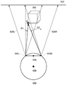
- FIG. 15A and FIG. 15B are diagrams for explaining the advantage of not performing the correction of the viewpoint position in the Z direction.
- calculation is simplified by not performing correction of the viewpoint position with respect to movement in the depth direction of the viewpoint, but there are other advantages as well.
- FIG. 15A shows the positional relationship between the truncated pyramid 630, the three-dimensional object 600, and the screen 610.
- the origin 640 of the viewing platform 630 is at this position, the entire three-dimensional object 600 is inside the viewing platform 630, so that the entire image of the three-dimensional object 600 is displayed on the screen 610.
- FIG. 15B shows the positional relationship when the viewpoint moves in the Z direction.
- the two-dimensional coordinates (wposT, hposT) of the parietal marker 110T For example, from the two-dimensional coordinates (wposT, hposT) of the parietal marker 110T, the two-dimensional coordinates (wposL, hposL) of the left head marker 110L, and the two-dimensional coordinates (wposR, hposR) of the right head marker 110R, a point (wposL , HposL) and a point (wposR, hposR) are obtained, and a change in distance between the straight line and the two-dimensional coordinates (wposT, hposT) of the parietal marker 110T is detected, and approximately the parietal marker 110T and the screen It is possible to correct the distance d with
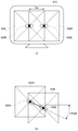
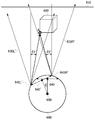
- FIG. 16A is a view for explaining the positional relationship between the sight mounts 630L and 630R, the three-dimensional object 600, and the screen 610 when viewed from directly above the head 660 of the user.
- the user points his head 660 directly in front of the screen 610.
- reference numeral 640 indicates a middle point between the origin 640L of the left-eye truncated cone 630L and the origin 640R of the right-eye viewpoint 630R.
- Reference numeral 650 indicates the rotation axis of the head 660.
- the user sees the position (Ax, Az) of the point A on the three-dimensional object 600 from the origins 640L and 640R of the left and right pedestals 630L and 630R.
- the user assumes that the point A of the three-dimensional object 600 is in the direction of an angle ⁇ 1 with respect to the direct front direction of the left eye cone 630L, and in the direction of an angle ⁇ 2 with respect to the direct front direction of the right eye eye cone 630R. It is considered to estimate the position of point A in the dimensional space.
- FIG. 16B is a view for explaining the new sight mounts 630L 'and 630R' when the user turns the head 660.
- the user sees the point A of the three-dimensional object 600 by moving the eyeball while rotating the head 660 about the rotation axis 650 by the rotation angle ⁇ .
- the user sees the position of the point A from the origins 640L 'and 640R' of the left and right truncated cones 630L 'and 630R', and the point A is in the direction of the angle ⁇ 1 'with respect to the direct front direction of the left eye cone 630L'.
- the angle correction is performed cognitively with respect to the sight line angles ⁇ 1 ′ and ⁇ 2 ′.
- the point is rotated as the head 660 rotates.
- A appears to move in the opposite direction to the direction of rotation, so that the parietal marker 110T is located more back than directly above the midpoint of the origin of the two frustums, ie closer to the center of rotation 650 of the head 660
- the point A appears to move in the same direction as the head 660 rotates. Therefore, when the mounting position of the hair band 100 is adjusted so that the point A appears to be stationary even when the head 660 is rotated, the parietal marker 110T is just right above the midpoint between the origins of the two frustums It will be.
- FIG. 16C is a diagram for explaining approximate sight mounts 630L ′ ′ and 630R ′ ′ when the user turns the head 660.
- the user sees the position of the point A from the origins 640 L ′ ′ and 640 R ′ ′ of the left and right frustum pedestals 630 L ′ ′ and 630 R ′ ′, and the point A is directed to the front of the left eye cone 630 L ′ ′
- the direction of the angle ⁇ 1 ′ ′ is in the direction of the angle ⁇ 2 ′ ′ with respect to the direction in front of the right-eye view 630R ′ ′ of the right eye.
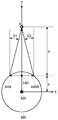
- FIG. 17A is a diagram showing a viewing angle when the head 660 is directed to the front.
- Ew is the distance between the left and right truncated pyramids, d the distance in the Z-axis direction from the midpoint 640 to the point A of the starting point of the truncated pyramid when there is no rotation of the head 660, and The distance from the point of rotation to the center of rotation 650 of the head 660 is a.
- FIG. 17B is a diagram showing the viewing angle when the head 660 is rotated by the rotation angle ⁇ .
- the user sees the position of the point A from the origins 640L 'and 640R' of the left and right truncated cones, and the point A is in the direction of the viewing angle ⁇ 1 'of the left eye and in the direction of the viewing angle ⁇ 2' of the right eye.
- the sight line angles ⁇ 1 'and ⁇ 2' at the rotation angle ⁇ are expressed by the following equations.
- tan ⁇ 1 ′ (a ⁇ sin ++ (Ew / 2) ⁇ cos)) / (d + a ⁇ (1 ⁇ cos)) + (Ew / 2) ⁇ sin))
- tan ⁇ 2 ′ ( ⁇ a ⁇ sin ++ (Ew / 2) ⁇ cos)) / (d ⁇ a ⁇ (1 ⁇ cos)) ⁇ (Ew / 2) ⁇ sin))
- FIG. 17C is a diagram showing a gaze angle when the rotation of the head 660 is approximated by translational movement.
- the user sees the position of the point A from the origins 640 L ′ ′ and 640 R ′ ′ of the left and right frustums, and the point A is in the direction of the eye angle ⁇ 1 ′ ′ of the left eye and in the direction of the eye angle ⁇ 2 ′ ′ of the right eye .
- the distance from the midpoint 640 '' of the two origins 640L '' and 640R '' of approximately two truncated pyramids to the rotation center 650 of the head 660 is a '.
- the gaze angles ⁇ 1 ′ ′ and ⁇ 2 ′ ′ when the rotation of the head is approximated by translational movement are expressed by the following equation.
- the distance d to the object is small, ie the object is close, it is best to wear the hair band 100 further back by Ew / 2d than the position of the midpoint between the origins of the two frustums It is. Therefore, when adjusting the mounting position of the hair band 100, it is desirable to set the distance d to the object to an average value to display the three-dimensional object for calibration. However, since this adjustment amount Ew / 2d is sufficiently small, it may often be practically ignored.
- the mounting position of the hair band 100 includes the adjustment amount depending strictly on the distance d to the object because the present method does not measure the position of the marker in the Z direction. In this method, since only the two-dimensional coordinates of the marker on the photographed image are used, the correction algorithm of the viewpoint position is simplified, and an error does not enter the calculation.
- the user adjusts the mounting position of the hair band 100 by itself to find the position at which the object appears stationary, including the adjustment amount Ew / 2d depending on the distance d to the object. The position is adjusted to the optimal position.
- markers such as infrared light emitting diodes attached to the head, in particular to the top of the head, right and left side of the head.
- These two-dimensional coordinates are detected, and the viewpoint position is corrected in real time from the two-dimensional coordinates of the marker to generate a parallax image.
- the object to be viewed stereoscopically can not move, and it is possible to eliminate discomfort such as intoxication, and more accurate three-dimensional shape recognition is possible.
- by correcting the viewpoint position with respect to the rotation of the head around the vertical axis of the sense and the tilt of the head it is possible to prevent the occurrence of unnatural artifacts and to present a natural stereoscopic image. .
- the viewpoint position is corrected from the two-dimensional coordinates of the marker, the viewpoint position can be corrected at high speed with a small amount of calculation. The small amount of calculation results in the reduction of the latency for the correction process and the reduction of the sickness.
- the method of correcting the viewpoint position has been described for the case where the user stereoscopically views the parallax image displayed on the display 300.
- the user mounts the head mounted display on the head It can be applied to the case of viewing a video.
- the correction is performed using the viewpoint position correction method described in the present embodiment. It can be configured to output a stereoscopic image according to the position of the viewpoint.
- 10 imaging unit 20 marker detection unit, 30 viewpoint position correction unit, 40 three-dimensional image generation unit, 50 three-dimensional model storage unit, 60 display unit, 70 calibration unit, 72 head marker coordinate acquisition unit, 74 left head marker coordinates Acquisition unit, 76 right side head marker coordinate acquisition unit, 78 translational movement calculation unit, 80 head tilt calculation unit, 82 translational correction amount calculation unit, 84 shift amount calculation unit, 86 viewpoint position update unit, 100 hair band with marker, 110 markers, 200 game consoles, 210 stereo image generating devices, 300 displays, 310 cameras, 400 stereo glasses.
- It can be used as a technology for generating stereoscopic images.
Abstract
マーカー検出部20は、ユーザの頭部に装着された装身具の複数のマーカーの撮影画像をスキャンして複数のマーカーの撮影画像上の2次元座標を検出する。視点位置補正部30は、マーカーのZ方向の座標を用いることなく、検出された複数のマーカーの2次元座標を用いて、ユーザの視点位置を補正する。立体画像生成部40は、補正された視点位置から3次元オブジェクトを見た場合の視差画像を生成する。
Description
この発明は、立体映像を生成する画像生成装置、画像生成方法および較正方法に関する。
映像を立体的に提示できる3次元テレビやヘッドマウントディスプレイ等の3次元表示デバイスが利用されている。携帯電話や携帯ゲーム機等の携帯端末機において映像を立体的に提示できるデバイスも開発されており、一般のユーザが立体的な映像を視聴する機会が増加してきている。
立体的な映像を表示する3次元表示デバイスは、ユーザの左右の眼に視差のある画像を見せることでユーザが画像を立体視することを可能にする。左右の眼に視差のある画像を見せるために特殊な光学メガネを利用する方式や、光学メガネを使わずにパララックスバリアやレンチキュラーレンズを用いる方式などがある。
このような3次元表示デバイスによる立体視では、ユーザの視点位置の情報が正確に得られ、また、視点位置が固定して動かないことが前提となっている。しかし、ユーザに頭を全く動かさないように求めることは現実的ではない。視点位置が動かないことを前提に生成された視差画像をユーザが立体視している場合に、ユーザが少しでも頭を動かしたり、傾けたりすると、視点位置が変位し、見ている立体映像が揺れ動くため、見づらさを感じたり、酔いが生じたりする。
本発明はこうした課題に鑑みてなされたものであり、その目的は、視点が変位しても安定した立体映像を生成することのできる画像生成装置、画像生成方法および較正方法を提供することにある。
上記課題を解決するために、本発明のある態様の画像生成装置は、ユーザの頭部に装着された装身具の複数のマーカーの撮影画像をスキャンして前記複数のマーカーの撮影画像上の2次元座標を検出するマーカー検出部と、マーカーのZ方向の座標を用いることなく、検出された前記複数のマーカーの2次元座標を用いて、ユーザの視点位置を補正する視点位置補正部と、補正された視点位置から3次元オブジェクトを見た場合の視差画像を生成する立体画像生成部とを含む。
本発明の別の態様は、較正方法である。この方法は、ユーザの頭部に装着された装身具の複数のマーカーの撮影画像をスキャンして前記複数のマーカーの撮影画像上の2次元座標を検出するマーカー検出ステップと、マーカーのZ方向の座標を用いることなく、検出された前記複数のマーカーの2次元座標を用いて、ユーザの視点位置を補正する視点位置補正ステップと、補正された視点位置から較正用3次元オブジェクトを見た場合の視差画像を生成する立体画像生成ステップと、頭部を動かしても立体視された較正用3次元オブジェクトが静止するように、ユーザの頭部に装着された装身具を前後させてマーカーの位置を調整するようユーザに促す較正ステップとを含む。
本発明のさらに別の態様は、画像生成方法である。この方法は、ユーザの頭部に装着された装身具の複数のマーカーの撮影画像をスキャンして前記複数のマーカーの撮影画像上の2次元座標を検出するマーカー検出ステップと、マーカーのZ方向の座標を用いることなく、検出された前記複数のマーカーの2次元座標を用いて、ユーザの視点位置を補正する視点位置補正ステップと、補正された視点位置から3次元オブジェクトを見た場合の視差画像を生成する立体画像生成ステップとを含む。
なお、以上の構成要素の任意の組合せ、本発明の表現を方法、装置、システム、コンピュータプログラム、データ構造、記録媒体などの間で変換したものもまた、本発明の態様として有効である。
本発明によれば、視点が変位しても安定した立体映像を表示することができる。
図1は、3次元ディスプレイ装置を説明する図である。3次元ディスプレイ装置は、ゲーム機200と、ディスプレイ300と、カメラ310とを含む。
ディスプレイ300は、無線通信またはUSBなどの周辺機器を接続するインタフェースでゲーム機200に接続される。ゲーム機200は、さらにネットワークを介してサーバに接続されてもよい。ディスプレイ300は、ゲーム機200の代わりに、コンピュータや携帯端末に接続されてもよい。カメラ310は、ディスプレイ300の上部などの設置され、ディスプレイ300を見ているユーザを撮影し、撮影した画像をゲーム機200に供給する。
図2(a)および図2(b)は、ユーザが装着するマーカー付きヘアバンド100を説明する図である。
図2(a)は、マーカー付きヘアバンド100の構成図である。ヘアバンド100は頭頂部マーカー110Tと、左側頭部マーカー110Lと、右側頭部マーカー110Rとを有する。ユーザがヘアバンド100を装着すると、頭頂部マーカー110Tはユーザの頭部、左側頭部マーカー110Lと右側頭部マーカー110Rはユーザの左右の側頭部に設けられる。図2(b)は、ユーザがマーカ付きヘアバンド100を装着した様子を示す。これらのマーカーは一例として赤外線発光ダイオードである。
ここでは、ヘアバンドにマーカーを搭載したが、ユーザの頭部に装着し、装着位置を前後に調整できるものであれば、ヘアバンドに限らず、任意の頭部用装身具を用いることができる。たとえば、ヘッドセットであってもよく、帽子であってもよい。
図3は、マーカー付きヘアバンド100を装着したユーザがディスプレイ300を見ている様子を説明する図である。
ユーザはディスプレイ300から距離dだけ離れた位置からディスプレイ300を観察している。この例では、ユーザは立体視用メガネ400を装着して視差画像が表示されたディスプレイ300のスクリーンを見ている。ディスプレイ300の上部に設置されたカメラ310は、マーカー付きヘアバンド100を装着したユーザの頭部を撮影する。
カメラ310は、赤外線透過フィルタを備えており、カメラ310により撮影されたユーザの頭部の画像から輝点を検出する画像処理により、ヘアバンド100の頭頂部マーカー110T、左側頭部マーカー110L、および右側頭部マーカー110Rの位置を検出することができる。
図4は、マーカー110の発光分布をカメラ310が検知する様子を示す図である。マーカー110の電力消費を最小化するために、発光分布に方向性のある発光ダイオードが使用されるが、カメラ310がマーカー110の光を撮像してマーカー110の位置を検出する際の位置の検出精度は発光分布に依存することになる。
赤外線発光ダイオードの発光強度分布は符号112で示すように正面方向に広がっており、発光ダイオードの正面から見ると発光分布がほぼ対称で急激な変化も少ないが、斜め方向から見ると不均一な光の強度分布が観測される。
カメラ310が発光ダイオードの正面からの光116を捉える場合、符号114で塗りつぶした部分の面積の重心がマーカー110の位置として検出され、高い精度でマーカー110の位置を検出することができる。一方、カメラ310が発光ダイオードの斜め方向からの光118を捉える場合は、光量が極端に少なくなり、また角度により不均一になるため、重心位置の測定精度が急激に低下し、マーカー110の位置を正確に検出することが困難になる。
図5(a)は、ヘアバンド100の3つのマーカー110T、110L、110Rとカメラ310の位置関係を説明する図である。頭頂部マーカー110Tは、カメラ310と正対する位置にあるため、カメラ310が頭頂部マーカー110Tの像を撮影して頭頂部マーカー110Tの2次元座標を高い精度で測定することができる。それに対して、左側頭部マーカー110L、右側頭部マーカー110Rはカメラ310から見て斜め方向に位置するため、2次元座標の測定精度が低くなる。
図5(b)は、カメラ310により撮影された左側頭部マーカー110Lの像510Lと、右側頭部マーカー110Rの像510Rを示す図である。左側頭部マーカー110Lの像510Lの2次元座標には測定誤差512Lが存在し、右側頭部マーカー110Rの像510Rの2次元座標には測定誤差512Rが存在し、測定精度は低い。しかし、ユーザが体を起こした状態でディスプレイを見ることを前提とすると、これらの測定誤差512L、512Rは水平方向であるから、頭部の傾きを検出する際には、水平方向の誤差は問題とならず、頭部の傾き角度vAngleの測定の際には誤差の影響を最小にすることができる。
本実施の形態では、頭頂部マーカー110Tの2次元座標を基準として、視点位置の補正量を決定する。視点位置の補正が適切にできるように、ユーザがヘアバンド100の位置を前後に動かし、頭頂部マーカー110Tの位置を調整する。これにより、個人差を最小化し、非常に少ない演算量でステレオ表示の際の視点位置の補正処理を実現することができる。
また、左側頭部マーカー110Lおよび右側頭部マーカー110Rの2次元座標から頭部の傾きを検出して、追加のステレオ表示補正を行う。
頭頂部マーカー110T、左側頭部マーカー110Lおよび右側頭部マーカー110RのZ方向の座標は用いない。頭頂部マーカー110Tからは2次元座標すなわち頭部のXY平面における位置のみを、左側頭部マーカー110Lおよび右側頭部マーカー110Rからは頭部の傾き角度のみを取り出して補正計算に使用することで、測定誤差の影響の少ない安定した視点位置の補正処理を実現することができる。
なお、左側頭部マーカー110Lおよび右側頭部マーカー110Rがカメラ310の正面方向を向くように角度をつけてヘアバンド100に設置すれば、左側頭部マーカー110Lおよび右側頭部マーカー110Rについても2次元座標の内、水平方向の測定精度を高くすることができるが、これはカメラ310からヘアバンド100までの距離が一定の場合にしか効果がないので、あまり現実的な解決方法ではない。本実施の形態では、左側頭部マーカー110Lおよび右側頭部マーカー110Rの2次元座標の内、水平方向の測定精度が低いことを前提とし、測定誤差の影響を受けないように、左側頭部マーカー110Lおよび右側頭部マーカー110Rについては検出された2次元座標を直接用いることはせずに、左側頭部マーカー110Lと右側頭部マーカー110Rを結ぶ線が水平方向に対してなす角度(すなわちユーザの頭部の傾き角度vAngle)を求める。傾き角度を求める過程で、左側頭部マーカー110Lの2次元座標の測定誤差と右側頭部マーカー110Rの2次元座標の測定誤差を相殺することができる。
図6は、本実施の形態に係る立体画像生成装置210の機能構成図である。同図は機能に着目したブロック図を描いており、これらの機能ブロックはハードウエアのみ、ソフトウエアのみ、またはそれらの組合せによっていろいろな形で実現することができる。
立体画像生成装置210は、ディスプレイ300に接続されたゲーム機200に実装されるが、立体画像生成装置210の少なくとも一部の機能をディスプレイ300の制御部に実装してもよい。あるいは、立体画像生成装置210の少なくとも一部の機能を、ネットワークを介してゲーム機200に接続されたサーバに実装してもよい。
撮影部10は、カメラ310により撮影されたマーカー付きヘアバンド100を装着したユーザの頭部の撮影画像をメモリに記憶する。マーカー検出部20は、撮影画像をスキャンして頭頂部マーカー110T、左側頭部マーカー110L、および右側頭部マーカー110Rの2次元座標を検出し、視点位置補正部30に供給する。
視点位置補正部30は、マーカー検出部20から取得した頭頂部マーカー110T、左側頭部マーカー110L、および右側頭部マーカー110Rの2次元座標にもとづいて、視点位置を補正し、更新された視点位置の情報を立体画像生成部40に与える。ここで、視点位置補正部30は、各マーカー110T、110L、110RのZ方向の座標、すなわち奥行き情報を用いずに、視点位置を補正することに留意すべきである。
立体画像生成部40は、3次元モデル記憶部50から表示すべきオブジェクトの3次元モデルを読み出し、視点位置補正部30から与えられた更新された視点位置から見た場合の視差を有する左目用画像および右目用画像を生成し、表示部60に供給する。表示部60は、左目用画像および右目用画像をディスプレイ300に表示する。
較正(キャリブレーション)部70は、立体画像生成部40にキャリブレーション用の3次元オブジェクトを生成するように指示する。較正部70はまた、マーカー付きヘアバンド100の装着位置を調整して、頭部を動かしてもキャリブレーション用の3次元オブジェクトが動かない装着位置を探るようにユーザに促すメッセージをディスプレイ300に表示するように表示部60に指示する。表示部60はキャリブレーション用の3次元オブジェクトの視差画像をディスプレイ300に表示するとともに、ユーザにマーカー付きヘアバンド100の装着位置を調整するよう促すメッセージをディスプレイ300に表示する。このメッセージを音声でユーザに提供してもよい。
図7は、視点位置補正部30の詳細な機能構成図である。頭頂部マーカー座標取得部72、左側頭部マーカー座標取得部74、右側頭部マーカー座標取得部76は、マーカー検出部20からそれぞれ頭頂部マーカー110T、左側頭部マーカー110L、右側頭部マーカー110Rの座標位置を取得する。
並進移動計算部78は、頭頂部マーカー110Tの2次元座標を用いて、ユーザの視点の並進移動を検出する。
頭部傾き計算部80は、左側頭部マーカー110Lおよび右側頭部マーカー110Rの2次元座標を用いて、ユーザの頭部の傾き角度を計算し、並進補正量計算部82およびシフト量計算部84に与える。
並進補正量計算部82は、ユーザの視点の並進移動とユーザの頭部の傾き角度から視点位置の並進補正量を計算し、視点位置更新部86に与える。
シフト量計算部84は、ユーザの頭部の傾き角度を用いて、ユーザの頭部の傾きに伴う視点位置のシフト量を計算し、視点位置更新部86に与える。
視点位置更新部86は、視点位置の並進補正量およびシフト量を用いて視点位置を更新し、更新後の視点位置の情報を立体画像生成部40に供給する。
図8は、カメラ310による撮影画像500における頭頂部マーカー110T、左側頭部マーカー110L、および右側頭部マーカー110Rを示す図である。撮影画像500は横Wピクセル、縦Hピクセルの画像である。マーカー検出部20は、撮影画像500の左上を(0,0)として、頭頂部マーカー110Tの2次元座標(wposT,hposT)、左側頭部マーカー110Lの2次元座標(wposL,hposL)、右側頭部マーカー110Rの2次元座標(wposR,hposR)をピクセル単位で求める。
図9(a)および図9(b)は、マーカー検出部20が撮影画像500をスキャンして頭頂部マーカー110T、左側頭部マーカー110L、および右側頭部マーカー110Rを検出する方法を説明する図である。
まず、図9(a)に示すように、撮影画像500の左上から1ライン毎にスキャンして頭頂部マーカー110Tを検出する。頭頂部マーカー110Tの2次元座標(wposT,hposT)が検出されると、図9(b)に示すように、撮影画像500を頭頂部マーカー110Tの位置で左右に分けて、左領域において上から1ライン毎にスキャンして右側頭部マーカー110Rの2次元座標(wposR,hposR)を検出し、右領域において上から1ライン毎にスキャンして左側頭部マーカー110Lの2次元座標(wposL,hposL)を検出する。
この2段階スキャンによって3つのマーカー110T、110L、110Rのいずれかが検出されない場合、エラーとして扱い、前回のスキャンで得られたマーカー110T、110L、110Rの位置座標を続けて用いる。
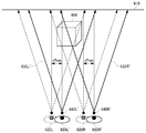
図10は、3次元オブジェクト600をスクリーン610にステレオ表示する際の左右の目の視錐台630L、630Rを説明する図である。
視点位置の補正アルゴリズムを説明するために、以下の3つの座標系を定義する。
(1)カメラ入力座標系
カメラ310による撮影画像の2次元座標系であり、座標系の単位は撮影画像のピクセル単位である。
(2)ワールド座標系
3次元オブジェクト600が存在する3次元空間の座標系である。右目の透視投影の原点と左目の透視投影の原点の中点をワールド座標系の原点とし、ディスプレイ300のスクリーンに向かう方向をZ軸とし、水平方向をX軸、垂直方向をY軸とする。座標系の単位は実空間の長さの単位である。
(3)ディスプレイのスクリーン座標系
ディスプレイ300のピクセル空間で表される2次元のスクリーン座標系であり、座標系の単位はディスプレイ300の表示ピクセル単位である。
(1)カメラ入力座標系
カメラ310による撮影画像の2次元座標系であり、座標系の単位は撮影画像のピクセル単位である。
(2)ワールド座標系
3次元オブジェクト600が存在する3次元空間の座標系である。右目の透視投影の原点と左目の透視投影の原点の中点をワールド座標系の原点とし、ディスプレイ300のスクリーンに向かう方向をZ軸とし、水平方向をX軸、垂直方向をY軸とする。座標系の単位は実空間の長さの単位である。
(3)ディスプレイのスクリーン座標系
ディスプレイ300のピクセル空間で表される2次元のスクリーン座標系であり、座標系の単位はディスプレイ300の表示ピクセル単位である。
ステレオ表示は、人間の左目620Lと右目620Rの間隔をEwとして、左目用に-Ew/2、右目用にEw/2だけ並行移動した視錐台630L、630Rを用いて3次元オブジェクト600を透視投影することによって行う。なお、実際の眼球の位置は、視錘台630L、630Rの原点640L、640Rよりも前にあると考えられるが、ここでは簡単のため、視錘台630L、630Rの原点640L、640Rの位置に眼球を描いている。
実際の計算では、透視変換の視錘台の座標系を固定として、例えば左目用には3次元オブジェクト600を-(-Ew/2)=Ew/2だけワールド座標系上で移動し、生成された画像をスクリーン座標系で上記に相当する量だけ反対方向に移動する。
スクリーンから視点までの距離は固定の設定値とする。カメラ310によりユーザの視点のZ座標(奥行き)を計測することも可能であるが、余分な計算処理により表示画像の不安定性が増すため、ここではZ座標は測定せず、Z方向の視点位置の補正を行わない。Z座標を使わず、撮影画像上のマーカーの2次元座標(X,Y)だけを用いて視点位置を補正するため、誤差の影響を最小化することができる。
図11は、視点が並進移動したときの視点位置の並進補正量を説明する図である。視点がX軸(水平方向)にxTranだけ並進移動したときの左目620L’の視錐台630L’と右目620R’の視錐台630R’が図示されている。
並進移動計算部78は、カメラ入力座標系の頭頂部マーカー110Tの位置(wposT,hposT)から3次元オブジェクト600のワールド座標系における表示位置の補正量(xTran,yTran)を以下のように計算する。この計算では、ユーザの両目は水平に保たれていると仮定する。
xTran=-(wposT-wRef)・wScale
yTran= (hposT-hRef)・hScale
yTran= (hposT-hRef)・hScale
ただし(wRef,hRef)はカメラ入力座標系の中心となる基準点。これは、例えばカメラ310がディスプレイ300のスクリーンの中央上端にある場合は、wRefはカメラ入力座標系の左右の視錘台の中心位置のX座標でよく、ワールド座標系の原点に人間の両目の透視変換の中心がある場合、hRefはカメラ310で検出される頭頂部マーカー110Tの位置のY座標でよい。
wScale、hScaleは、カメラ入力座標系上で得られたマーカーのピクセル位置を、ワールド空間の座標系へ変換するためのスケーリング係数である。本来はカメラからマーカーまでの距離を変数とした関数になるが、本手法の場合はユーザがディスプレイ300に対して最適な位置付近で視聴を行うことを仮定するため、定数で処理する。
また、カメラ入力座標系の左側頭部マーカー110Lの2次元座標(wposL,hposL)と右側頭部マーカー110Rの2次元座標(wposR,hposR)の関係からユーザの頭部のワールド座標系での傾きを計測する。この場合も、ワールド座標系でのZ方向の傾きは無視し、カメラ座標系およびスクリーン座標系と平行な2次元平面での傾きを扱う。この傾きの角度をvAngleとする。vAngleは、下記の計算式により求められる。
vAngle=arcTan((hposR-hposL)/(wposR-wposL))
並進補正量計算部82は、頭部の傾きがないと仮定して求めた上記の並進補正量xTran、yTranを頭部の傾き角度vAngleを用いてさらに以下のように補正する。
xTran=(-(wpos0-wRef)+hDist・sin(vAngle))・wScale
yTran=(hpos0-hRef+hDist・(1-cos(vAngle)))・hScale
yTran=(hpos0-hRef+hDist・(1-cos(vAngle)))・hScale
ただし、hDistはカメラ入力座標系上での頭頂部マーカー110Tの位置とユーザの両目の基準位置(ワールド座標系の原点)の間の距離である。
図12(a)および図12(b)は、頭部の傾き角度vAngleによる頭頂部マーカー110Tの位置の変化を説明する図である。図12(a)は、ユーザの両目が水平である場合の頭頂部マーカー110Tの位置を示しており、頭頂部マーカー110Tはユーザの両目の中心からhDistだけ離れている。図12(b)は、ユーザの両目が水平方向に対して角度vAngleだけ傾いた場合の頭頂部マーカー110Tの位置を示しており、頭頂部マーカー110Tは水平方向(X軸)にhDist・sin(vAngle)だけ、垂直方向(Y軸)にhDist・(1-cos(vAngle))だけ変位している。この変位を考慮して、並進補正量xTran、yTranは上記の式のように補正される。
こうして頭部の傾きも考慮に入れて求められた並進補正量xTran、yTranは、カメラ入力座標系の3つのマーカー110T、110L、110Rの2次元座標の変化をもとに、立体視用の透視投影の視錘台の中心がワールド座標系の原点からどれだけずれたかを推定した値である。
図11では、水平方向だけを考えた場合の視錘台の移動を表しているが、垂直方向も同様である。図11からわかるように、この移動は、実際の3次元オブジェクト600をワールド座標系で-xTran、-yTranだけ移動させ、さらに生成された画像をスクリーン空間上でxTran、yTranに相当する量だけ移動させることにより得られる。
このスクリーン空間上でのピクセル単位の補正量xAdj、yAdjは下記の式で表される。
xAdj=-xTran/sScale
yAdj=-yTran/sScale
yAdj=-yTran/sScale
ただし、sScaleはワールド座標系からスクリーン座標系への座標変換係数である。X方向、Y方向で比率が異なる場合は、それぞれに合わせた値を用いる必要がある。
ユーザが頭部を左右に動かしたり、回転させると視錘台の中心がワールド座標系の原点からずれる。このずれに対して視点位置の補正をせずに左右の視差画像をディスプレイ300に表示すると、立体映像がユーザの頭部の並進運動や回転運動に応じて揺れ動いて見えるため、酔いが生じる。本実施の形態では、並進補正量xTran、yTranを求めて、視点位置を更新し、更新後の視点位置から見た場合の左右の視差画像を生成してディスプレイ300に表示する。これにより、ユーザが頭部を自然に動かしても立体映像が視点のずれに伴って揺れ動くことがないため、安定した立体映像を提示することができる。
図13(a)および図13(b)は、ユーザが頭部を傾けた場合の視錘台の中心の変位を説明する図である。
図13(a)のように、ユーザの両目620L、620Rの位置が水平に保たれている場合は、立体視のためには透視変換の視錘台630L、630RをそれぞれEw/2づつ平行移動させた両目画像を生成すればよい。
図13(b)のように、ユーザの両目が傾いている場合は、左目の視錘台630L、右目の視錘台630Rが斜め方向にずれるため、シフト量計算部84は、左側頭部マーカー110L、右側頭部マーカー110Rから得たユーザの両目の傾きvAngleを用いて、視錘台の平行移動量をシフト補正する。
この補正は、ワールド座標系上での左右の目の位置のシフト補正量xshift、yshiftとして、下記の式で表現される。
左目について
xShift= (Ew/2)・cos(vAngle)
yShift=-(Ew/2)・sin(vAngle)
右目について
xShift=-(Ew/2)・cos(vAngle)
yShift= (Ew/2)・sin(vAngle)
左目について
xShift= (Ew/2)・cos(vAngle)
yShift=-(Ew/2)・sin(vAngle)
右目について
xShift=-(Ew/2)・cos(vAngle)
yShift= (Ew/2)・sin(vAngle)
実際にこの補正を行うには、視錘台の位置はもとのままとして、オブジェクトを逆の方向に移動する計算として表現する。このため、上記に相当する量だけ、スクリーン座標系上で得られた画像を反対方向に移動する。
スクリーン空間上でも、上記に対応したシフト補正を行う。シフト量をxShiftAdj,yShiftAdjと書くと、それらは左目、右目ともに下記の式で表される。
xShiftAdj=-xShift/sScale
yShiftAdj=-yShift/sScale
xShiftAdj=-xShift/sScale
yShiftAdj=-yShift/sScale
視点位置更新部86は、並進補正量xTran、yTranとシフト補正量xshift、yshiftを加算して視点位置の移動量を求め、視点位置を更新する。なお、頭の傾きによるシフト補正量を考慮して視点位置を補正するのはオプションであり、ユーザが頭を水平に保つことを前提にvAngle=0と仮定して、頭部の傾きを考慮に入れない並進補正量のみで視点位置を補正してもよい。
図14は、マーカー付きヘアバンド100の装着位置と視錘台の射影原点の関係を説明する図である。
視錘台の射影原点640は、人間の目の焦点位置であり、実際の目の位置よりも奥にあると考えられる。ここで、視錘台の射影原点640とは、正確に言えば、左右の2つの視錘台があるため、各視錘台の射影原点の中点のことであるが、ここでは、簡単のため、視錘台の射影原点と称する。
視点位置の補正アルゴリズムでは、視錘台の射影原点640をワールド座標系の原点として用いて画像の補正を行う。これは、視点位置を検出する基準として用いられるヘアバンド100の頭頂部マーカー110Tが、ワールド座標系の原点すなわち視錘台の射影原点640の真上にhDistだけ離れた位置にあることを仮定していることになる。
しかしながら、視錘台の射影原点は人間の目の焦点位置であるから、通常は直接その位置を計測することはできない。そこで、ヘアバンド100のように頭部に装着して前後に装着位置を調整可能なアクセサリにマーカーを組み込み、ユーザがスクリーン上で映し出される立体画像が自然に見えるように自らヘアバンド100の装着位置を調整することで、各人に合わせた理想的な視錘台の射影原点を設定することを可能にしている。
較正部70は、キャリブレーション用の3次元オブジェクトの視差画像を生成してディスプレイ300に表示するように立体画像生成部40と表示部60に指示する。較正部70は、ユーザにマーカー付きヘアバンド100の装着位置を前後に調整するように画面上の文字や音声などで指示する。
ユーザは、ディスプレイ300に映し出されたキャリブレーション用の3次元オブジェクトの視差画像を立体視用メガネ400を通して見ながら、頭部を左右に動かしたり、回転させてもキャリブレーション用の3次元オブジェクトが動かないように、ヘアバンド100の装着位置を前後に調整する。ヘアバンド100の頭頂部マーカー110Tが、ちょうどそのユーザの視錘台の射影原点640の真上に位置したとき、視点位置の補正アルゴリズムが有効に働き、頭部を動かしてもキャリブレーション用の3次元オブジェクトは動かなくなる。これでキャリブレーションは終了し、較正部70は立体画像生成部40と表示部60に指示してキャリブレーション用の3次元オブジェクトの視差画像の生成と表示を終了させる。
従来は、例えば立体視用メガネ400の表面にマーカーをとりつけてカメラで撮影し、マーカーの位置を3次元的に計測して視錘台の射影原点を算出する方法が取られることがある。しかし、立体視用メガネ400にマーカーがある場合、視錘台の射影原点とはZ方向にずれているため、マーカーの位置から視錘台の射影原点を求めるために奥行き方向の正確な情報が必要となり、計算も複雑になる。また、立体視用メガネ400のマーカーを撮影してもユーザの頭部の回転と並進の区別がつきにくいことから、位置測定に誤差が生じやすい。さらに、各人の目の焦点位置に合わせた計算が必要になり、時間のかかる較正プロセスをユーザにメニュー操作を求めながら行う必要がある。
それに対して本実施の形態では、頭頂部マーカー110Tは、視錘台の射影原点の真上に調整されるため、頭頂部マーカー110Tマーカーと視錘台の射影原点はZ方向にずれがないから、視線位置の補正計算を簡略化できる。また、本実施の形態の較正手法では、ヘアバンド100の装着位置をユーザ自身が物理的に前後にずらすという極めて直感的な方法で個々人の目の焦点位置に合わせた調整が実現でき、誰でも容易にキャリブレーションを行うことができる。さらに、検出するマーカーの箇所が少ないためにマーカー毎の誤差の影響が少なく、非常に安定したキャリブレーションを行うことができる。
図15(a)および図15(b)は、視点位置のZ方向の補正を行わないことの利点を説明する図である。本実施の形態では、視点の奥行き方向に移動に対しては視点位置の補正をあえて行わないことで計算を簡略化しているが、これには他の利点もある。
図15(a)は、視錘台630と3次元オブジェクト600とスクリーン610の位置関係を示す。視錘台630の原点640がこの位置にあるときは、3次元オブジェクト600の全体が視錘台630の内側にあるため、スクリーン610に3次元オブジェクト600の画像がすべて表示される。
図15(b)は、視点がZ方向に移動した場合の位置関係を示す。視点がスクリーン610に近づいたときにZ方向の視点の位置補正を行うと、3次元オブジェクト600の一部が視錘台630の外側にはみ出すため、3次元オブジェクト600の画像がスクリーン610の縁にかかってしまう。
よく知られているように、立体視表示の場合、オブジェクトが画面の縁にかかると、額縁補正などの処理を行ったとしても、不自然に見えることは免れない。しかしながら、Z方向の視点位置の補正をあえて行わないのであれば、オブジェクトが多少Z方向に縮むようには見えるものの、画面の縁にかかる可能性は小さくなるため、結果的に見やすい画像を保つことが可能である。このように、Z方向の視点位置の補正をあえて行わないことは、視点位置補正アルゴリズムを簡単にするだけでなく、視点がスクリーンに近づいても自然な立体視表示を維持することを容易にするという副次的な効果も奏する。
なお、上記説明では、Z方向の補正を行わないことを前提として利点を説明したが、本実施の形態では、他の測定装置などを増やすことなしに、簡易的なZ方向の視点位置の補正を追加することも可能である。
例えば、頭頂部マーカー110Tの2次元座標(wposT,hposT)、左側頭部マーカー110Lの2次元座標(wposL,hposL)、右側頭部マーカー110Rの2次元座標(wposR,hposR)から、点(wposL,hposL)と点(wposR,hposR)を結ぶ直線を求め、この直線と頭頂部マーカー110Tの2次元座標(wposT,hposT)との距離の変化を検出し、近似的に頭頂部マーカー110Tとスクリーンとの距離dを補正することが可能である。
このように、頭頂部マーカー110T、左側頭部マーカー110Lおよび右側頭部マーカー110Rのそれぞれの正確な奥行き方向の座標値を求めることなく、奥行き方向の補正を行うことも可能である。
以下、図16A~図16Cを参照しながら、立体視されたオブジェクトが静止して見えるようにヘアバンド100の頭頂部マーカー110Tの位置を調整することでキャリブレーションが可能であることを人間の立体視モデルを用いて説明する。
図16Aは、ユーザの頭部660の真上から見た場合の視錘台630L、630Rと3次元オブジェクト600とスクリーン610の位置関係を説明する図である。この図では、ユーザは頭部660をスクリーン610に対して真正面に向けている。ここで、符号640は、左目の視錘台630Lの原点640Lと右目の視錘台630Rの原点640Rの中点を示す。符号650は、頭部660の回転軸を示す。
ユーザは3次元オブジェクト600上の点Aの位置(Ax,Az)を左右の視錘台630L、630Rの原点640L、640Rから見る。ユーザは、3次元オブジェクト600の点Aが左目の視錘台630Lの真正面方向に対して角度θ1の方向、右目の視錘台630Rの真正面方向に対して角度θ2の方向にあるものとして、3次元空間における点Aの位置を推定すると考えられる。
図16Bは、ユーザが頭部660を回した場合の新しい視錘台630L’、630R’を説明する図である。ユーザは回転軸650を中心として頭部660を回転角Φだけ回した状態で眼球を動かして3次元オブジェクト600の点Aを見る。
ユーザは点Aの位置を左右の視錘台630L’、630R’の原点640L’、640R’から見ており、点Aは左目の視錘台630L’の真正面方向に対して角度θ1’の方向、右目の視錘台630R’の真正面方向に対して角度θ2’の方向にある。θ1’>θ1、θ2’<θ2であることから、点Aは頭部660の回転方向とは逆方向に移動することになるが、このとき、人間は点Aがあくまでも静止していると認識するため、視線角度θ1’,θ2’に対して認知的に角度補正を行っていると考えられる。
ここで、人間には直接的に眼球の位置を知るセンサーはないと考えられるため、人間は、自分の首の回転から仮想的な左右二つの視錘台の原点の位置の移動を推測し、その位置から見るための角度補正を新しい視線角度θ1’,θ2’に対して行い、点Aが静止していると認識すると考えられる。この人間の認知処理のゆえに、二つの視錘台の原点の中点の真上にヘアバンド100の頭頂部マーカー110Tが来るように装着すると、視錘台の原点位置の補正処理が正確に行われ、ユーザが頭部660を回転させても点Aが静止して見えると考えられる。
この図から容易にわかるように、頭頂部マーカー110Tが二つの視錘台の原点の中点の真上よりも前方に位置するようにヘアバンド100を装着すると、頭部660の回転に伴い点Aは回転方向と逆方向に移動するように見え、頭頂部マーカー110Tが二つの視錘台の原点の中点の真上よりも後方、すなわち頭部660の回転中心650に近くに位置するようにヘアバンド100を装着すると、頭部660の回転に伴い点Aは回転方向と同方向に移動するように見える。したがって、頭部660を回転しても点Aが静止して見えるようにヘアバンド100の装着位置を調整すると、頭頂部マーカー110Tは二つの視錘台の原点の中点のちょうど真上に来るようになる。
ただし、本手法ではZ方向の視点位置の補正を行わないため、頭部660を回転させた場合でも、Z方向を考慮しないで、図16Cのように視錘台の原点が並進移動したものとして近似して扱うことになる。
図16Cは、ユーザが頭部660を回した場合の近似的な視錘台630L’’、630R’’を説明する図である。
ユーザは点Aの位置を左右の視錘台630L’’、630R’’の原点640L’’、640R’’から見ており、点Aは左目の視錘台630L’’の真正面方向に対して角度θ1’’の方向、右目の視錘台630R’’の真正面方向に対して角度θ2’’の方向にある。この近似の結果、θ1”>θ1’、θ2”<θ2’となり、点Aは静止位置よりやや右に動いて見えると予想されるが、人間の目の焦点位置は眼球よりも奥の位置にあり、本手法では、頭頂部マーカー110は頭部660の回転中心650に比較的近い位置に装着されることになり、この近似による計算誤差はほぼキャンセルされる。結果的に、ヘアバンド100の頭頂部マーカー110Tの位置を個人で調整することにより、立体画像が静止して見えるような表示系を構成することが可能になる。
次に、図17A~図17Cを参照しながら、本実施の形態のキャリブレーションの妥当性を詳しく説明する。ここでは、3次元オブジェクト600の点Aが水平軸(X軸)の原点上にある場合に本手法の妥当性を計算式により示す。
図17Aは、頭部660を正面に向けている場合の視線角度を示す図である。ユーザは点Aの位置を左右の視錘台の原点640L、640Rから見ており、点Aは左目の視線角度θ1の方向、右目の視線角度θ2(=θ1)の方向にある。
左右の視錘台の間隔をEw、頭部660の回転がないときの視錘台の原点の中点640から点AまでのZ軸方向の距離をd、視錘台の原点の中点640から頭部660の回転中心650までの距離をaとする。頭部の回転角Φ=0の場合の視線角度θ1、θ2は以下の式で表される。
tanθ1=tanθ2=Ew/2d
図17Bは、頭部660を回転角Φだけ回転した場合の視線角度を示す図である。ユーザは点Aの位置を左右の視錘台の原点640L’、640R’から見ており、点Aは左目の視線角度θ1’の方向、右目の視線角度θ2’の方向にある。回転角Φのときの視線角度θ1’、θ2’は次式で表される。
tanθ1’=(a・sinΦ+(Ew/2)・cosΦ)/(d+a・(1-cosΦ)+(Ew/2)・sinΦ)
tanθ2’=(-a・sinΦ+(Ew/2)・cosΦ)/(d-a・(1-cosΦ)-(Ew/2)・sinΦ)
tanθ2’=(-a・sinΦ+(Ew/2)・cosΦ)/(d-a・(1-cosΦ)-(Ew/2)・sinΦ)
図17Cは、頭部660の回転を並進移動で近似した場合の視線角度を示す図である。ユーザは点Aの位置を左右の視錘台の原点640L’’、640R’’から見ており、点Aは左目の視線角度θ1’’の方向、右目の視線角度θ2’’の方向にある。近似的に用いられる2つの視錘台の原点640L’’、640R’’の中点640’’から頭部660の回転中心650までの距離をa’とする。頭部の回転を並進移動で近似した場合の視線角度θ1’’、θ2’’は次式で表される。
tanθ1”=(a’・sinΦ+Ew/2)/d
tanθ2”=(-a’・sinΦ+Ew/2)/d
tanθ2”=(-a’・sinΦ+Ew/2)/d
ここで回転角Φが0に近い場合、回転角Φのときの視線角度θ1’、θ2’の式および並進移動で近似した場合の視線角度θ1’’、θ2’’は以下のように簡略化される。
tanθ1’=(a・Φ+Ew/2)/(d+(Ew/2)・Φ)=(a・Φ+Ew/2-(Ew/2d)・Φ)/d
tanθ2’=(-a・Φ+Ew/2)/(d-(Ew/2)・Φ)=(-a・Φ+Ew/2+(Ew/2d)・Φ)/d
tanθ2’=(-a・Φ+Ew/2)/(d-(Ew/2)・Φ)=(-a・Φ+Ew/2+(Ew/2d)・Φ)/d
tanθ1”=(a’・Φ+Ew/2)/d
tanθ2”=(-a’・Φ+Ew/2)/d
tanθ2”=(-a’・Φ+Ew/2)/d
ここでθ1’=θ1”の条件を加えると、a’=a-Ew/2dが得られ、このときθ2’=θ2”となる。θ1’=θ1”およびθ2’=θ2”の条件は回転と並進を区別しないことを意味する。
本手法では、マーカーのZ方向の位置の計測情報を全く使用しないが、対象物までの距離dに対応した距離a’=a-Ew/2dだけ頭の回転中心から離れた位置の真上にヘアバンド100の頭頂部マーカー110Tが来るようにヘアバンド100を装着することにより、3次元オブジェクトが頭の回転運動にたいして静止して見えるような表示系を実現することが可能になる。
対象物までの距離dが十分に大きい、すなわち対象物が十分遠くにある場合は、a’=aとなり、頭頂部マーカー110Tが二つの視錘台の原点の中点の真上に来るようにヘアバンド100を装着すれば対象物は静止して見える。
対象物までの距離dが小さい、すなわち対象物が近くにある場合は、二つの視錘台の原点の中点の位置よりEw/2dの分だけさらに後ろにヘアバンド100を装着するのが最適である。したがって、ヘアバンド100の装着位置を調整する際は、対象物までの距離dを平均的な値に設定して、キャリブレーション用の3次元オブジェクトを表示することが望ましい。ただし、この調整量Ew/2dは十分に小さいので、実用的には無視してよいことも多いであろう。
このようにヘアバンド100の装着位置が厳密には対象物までの距離dに依存した調整量を含むことになるのは、本手法ではZ方向のマーカーの位置を測定しないからである。本手法では、撮影画像上のマーカーの2次元座標のみを用いていることから、視点位置の補正アルゴリズムが簡単になり、また、計算に誤差が入り込まない。その一方で、ユーザが自分でヘアバンド100の装着位置を調整して対象物が静止して見える位置を見つけることで、対象物までの距離dに依存する調整量Ew/2dも含めてマーカーの位置を最適な位置に調整している。
上述のように、本実施の形態によれば、赤外線発光ダイオードなどのマーカーを頭部、特に頭頂部、左右の側頭部に取り付けたユーザを赤外線カメラなどで撮影し、撮影画像からこれらのマーカーの2次元座標を検出し、マーカーの2次元座標から視点位置をリアルタイムで補正して視差画像を生成する。これにより、立体視されるオブジェクトが動かなくなり、酔いなどの不快感を取り除くことができ、また、より正確な3次元形状の認識が可能である。特に、感覚的に重要な頭の垂直軸周りの回転と頭の左右の傾きに対して視点位置を補正することで、不自然なアーティファクトの発生を防ぎ、自然な立体映像を提示することができる。
検出すべきマーカーの個数が少なく、Z方向の座標値を用いないため、位置測定の誤差の影響を低減することができる。また、マーカーの2次元座標から視点位置を補正するため、少ない演算量で高速に視点位置を補正することができる。演算量が少ないことは結果的に補正処理にかかるレイテンシーを軽減させ、酔いを低減させる効果もある。
また、それぞれのマーカーのZ方向の座標値を必要としないため、計測に用いるカメラが一つで済むという利点もある。
以上、本発明を実施の形態をもとに説明した。実施の形態は例示であり、それらの各構成要素や各処理プロセスの組合せにいろいろな変形例が可能なこと、またそうした変形例も本発明の範囲にあることは当業者に理解されるところである。そのような変形例を説明する。
上記の実施の形態では、ディスプレイ300に表示された視差画像をユーザが立体視する場合について視点位置の補正方法を説明したが、同じ方法は、ユーザがヘッドマウントディスプレイを頭部に装着して立体映像を見る場合にも適用することができる。ユーザがヘッドマウントディスプレイを装着したまま頭部を動かしても、表示された3次元オブジェクトが動かないように見せたい場合に、本実施の形態で説明した視点位置の補正方法を用いて、更新された視点位置に応じて立体映像を出力するように構成することができる。
10 撮影部、 20 マーカー検出部、 30 視点位置補正部、 40 立体画像生成部、 50 3次元モデル記憶部、 60 表示部、 70 較正部、 72 頭頂部マーカー座標取得部、 74 左側頭部マーカー座標取得部、 76 右側頭部マーカー座標取得部、 78 並進移動計算部、 80 頭部傾き計算部、 82 並進補正量計算部、 84 シフト量計算部、 86 視点位置更新部、 100 マーカー付きヘアバンド、 110 マーカー、 200 ゲーム機、 210 立体画像生成装置、 300 ディスプレイ、 310 カメラ、 400 立体視用メガネ。
立体映像を生成する技術に利用できる。
Claims (7)
- ユーザの頭部に装着された装身具の複数のマーカーの撮影画像をスキャンして前記複数のマーカーの撮影画像上の2次元座標を検出するマーカー検出部と、
マーカーのZ方向の座標を用いることなく、検出された前記複数のマーカーの2次元座標を用いて、ユーザの視点位置を補正する視点位置補正部と、
補正された視点位置から3次元オブジェクトを見た場合の視差画像を生成する立体画像生成部とを含むことを特徴とする画像生成装置。 - 前記複数のマーカーは、少なくともユーザの頭部の頭頂部に設けられたマーカーを含み、
前記視点位置補正部は、
頭頂部のマーカーの2次元座標にもとづいて視点位置の並進補正量を求める並進補正量計算部と、
前記並進補正量にもとづいて視点位置を更新する視点位置更新部とを含むことを特徴とする請求項1に記載の画像生成装置。 - 前記複数のマーカーは、さらに左側頭部に設けられたマーカーと右側頭部に設けられたマーカーを含み、
前記視点位置補正部は、
左側頭部のマーカーの2次元座標および右側頭部のマーカーの2次元座標にもとづいて頭部の傾きを求める頭部傾き計算部と
頭部の傾きにもとづいて視点位置のシフト量を求めるシフト量計算部とをさらに含み、
前記並進補正量計算部は、頭頂部のマーカーの2次元座標および頭部の傾きにもとづいて視点位置の並進補正量を求め、
前記視点位置更新部は、前記シフト量および前記並進補正量にもとづいて視点位置を更新することを特徴とする請求項2に記載の画像生成装置。 - 較正用3次元オブジェクトの視差画像を前記立体画像生成部に生成させ、頭部を動かしても立体視された較正用3次元オブジェクトが静止するように、ユーザの頭部に装着された装身具を前後させてマーカーの位置を調整するようユーザに促す較正部をさらに含むことを特徴とする請求項1から3のいずれかに記載の画像生成装置。
- ユーザの頭部に装着された装身具の複数のマーカーの撮影画像をスキャンして前記複数のマーカーの撮影画像上の2次元座標を検出するマーカー検出ステップと、
マーカーのZ方向の座標を用いることなく、検出された前記複数のマーカーの2次元座標を用いて、ユーザの視点位置を補正する視点位置補正ステップと、
補正された視点位置から較正用3次元オブジェクトを見た場合の視差画像を生成する立体画像生成ステップと、
頭部を動かしても立体視された較正用3次元オブジェクトが静止するように、ユーザの頭部に装着された装身具を前後させてマーカーの位置を調整するようユーザに促す較正ステップとを含むことを特徴とする較正方法。 - ユーザの頭部に装着された装身具の複数のマーカーの撮影画像をスキャンして前記複数のマーカーの撮影画像上の2次元座標を検出するマーカー検出ステップと、
マーカーのZ方向の座標を用いることなく、検出された前記複数のマーカーの2次元座標を用いて、ユーザの視点位置を補正する視点位置補正ステップと、
補正された視点位置から3次元オブジェクトを見た場合の視差画像を生成する立体画像生成ステップとを含むことを特徴とする画像生成方法。 - ユーザの頭部に装着された装身具の複数のマーカーの撮影画像をスキャンして前記複数のマーカーの撮影画像上の2次元座標を検出するマーカー検出機能と、
マーカーのZ方向の座標を用いることなく、検出された前記複数のマーカーの2次元座標を用いて、ユーザの視点位置を補正する視点位置補正機能と、
補正された視点位置から3次元オブジェクトを見た場合の視差画像を生成する立体画像生成機能とをコンピュータに実現させることを特徴とするプログラム。
Priority Applications (1)
| Application Number | Priority Date | Filing Date | Title |
|---|---|---|---|
| US15/519,295 US10362297B2 (en) | 2014-10-31 | 2015-08-26 | Image generation apparatus, image generation method, and calibration method |
Applications Claiming Priority (2)
| Application Number | Priority Date | Filing Date | Title |
|---|---|---|---|
| JP2014222569A JP6588196B2 (ja) | 2014-10-31 | 2014-10-31 | 画像生成装置、画像生成方法および較正方法 |
| JP2014-222569 | 2014-10-31 |
Publications (1)
| Publication Number | Publication Date |
|---|---|
| WO2016067729A1 true WO2016067729A1 (ja) | 2016-05-06 |
Family
ID=55857075
Family Applications (1)
| Application Number | Title | Priority Date | Filing Date |
|---|---|---|---|
| PCT/JP2015/074010 WO2016067729A1 (ja) | 2014-10-31 | 2015-08-26 | 画像生成装置、画像生成方法および較正方法 |
Country Status (3)
| Country | Link |
|---|---|
| US (1) | US10362297B2 (ja) |
| JP (1) | JP6588196B2 (ja) |
| WO (1) | WO2016067729A1 (ja) |
Families Citing this family (4)
| Publication number | Priority date | Publication date | Assignee | Title |
|---|---|---|---|---|
| JP6798204B2 (ja) * | 2016-09-08 | 2020-12-09 | 富士ゼロックス株式会社 | 立位姿勢評価装置 |
| US10999567B2 (en) | 2017-08-01 | 2021-05-04 | Sony Interactive Entertainment Inc. | Image generating apparatus and image generating method |
| WO2019026183A1 (ja) | 2017-08-01 | 2019-02-07 | 株式会社ソニー・インタラクティブエンタテインメント | 画像生成装置および画像生成方法 |
| WO2022124398A1 (ja) * | 2020-12-10 | 2022-06-16 | 三菱電機株式会社 | 遠隔制御マニピュレータシステムおよび遠隔制御支援システム |
Citations (5)
| Publication number | Priority date | Publication date | Assignee | Title |
|---|---|---|---|---|
| JPH0628452A (ja) * | 1991-08-07 | 1994-02-04 | Nec Home Electron Ltd | 3次元画像処理装置 |
| JP2002300610A (ja) * | 2001-03-29 | 2002-10-11 | Sanyo Electric Co Ltd | 立体映像表示装置 |
| JP2012141502A (ja) * | 2011-01-05 | 2012-07-26 | Nippon Seiki Co Ltd | 視点位置検出装置、視点位置検出方法及び立体表示装置 |
| JP2013120150A (ja) * | 2011-12-08 | 2013-06-17 | Samsung Yokohama Research Institute Co Ltd | 人間位置検出システム及び人間位置検出方法 |
| US20140184588A1 (en) * | 2010-08-31 | 2014-07-03 | Nintendo Co., Ltd. | Eye tracking enabling 3d viewing on conventional 2d display |
Family Cites Families (10)
| Publication number | Priority date | Publication date | Assignee | Title |
|---|---|---|---|---|
| JP3443272B2 (ja) * | 1996-05-10 | 2003-09-02 | 三洋電機株式会社 | 立体映像表示装置 |
| JP2000315259A (ja) * | 1999-05-06 | 2000-11-14 | Sharp Corp | データベース作成装置及びデータベース作成プログラムを記録した記録媒体 |
| JP2007102343A (ja) * | 2005-09-30 | 2007-04-19 | Fujifilm Corp | 関心度測定装置および方法並びに関心度算出プログラム |
| JP2007232753A (ja) * | 2006-02-27 | 2007-09-13 | Eyemetrics Japan Co Ltd | 眼鏡仕様設定装置及び視野検出装置 |
| JP5066479B2 (ja) * | 2008-04-25 | 2012-11-07 | 横河電子機器株式会社 | 被指揮者識別装置及び指揮支援システム |
| US9544568B2 (en) * | 2009-06-05 | 2017-01-10 | Lg Electronics Inc. | Image display apparatus and method for operating the same |
| CN101750747B (zh) * | 2010-02-01 | 2013-04-24 | 刘武强 | 三维立体成像方法、系统和成像设备 |
| US20120050154A1 (en) * | 2010-08-31 | 2012-03-01 | Adil Jagmag | Method and system for providing 3d user interface in 3d televisions |
| JP2012223363A (ja) * | 2011-04-20 | 2012-11-15 | Tokyo Institute Of Technology | 手術用撮像システム及び手術用ロボット |
| JP6380881B2 (ja) * | 2012-07-31 | 2018-08-29 | Tianma Japan株式会社 | 立体画像表示装置、画像処理装置及び立体画像処理方法 |
-
2014
- 2014-10-31 JP JP2014222569A patent/JP6588196B2/ja active Active
-
2015
- 2015-08-26 US US15/519,295 patent/US10362297B2/en active Active
- 2015-08-26 WO PCT/JP2015/074010 patent/WO2016067729A1/ja active Application Filing
Patent Citations (5)
| Publication number | Priority date | Publication date | Assignee | Title |
|---|---|---|---|---|
| JPH0628452A (ja) * | 1991-08-07 | 1994-02-04 | Nec Home Electron Ltd | 3次元画像処理装置 |
| JP2002300610A (ja) * | 2001-03-29 | 2002-10-11 | Sanyo Electric Co Ltd | 立体映像表示装置 |
| US20140184588A1 (en) * | 2010-08-31 | 2014-07-03 | Nintendo Co., Ltd. | Eye tracking enabling 3d viewing on conventional 2d display |
| JP2012141502A (ja) * | 2011-01-05 | 2012-07-26 | Nippon Seiki Co Ltd | 視点位置検出装置、視点位置検出方法及び立体表示装置 |
| JP2013120150A (ja) * | 2011-12-08 | 2013-06-17 | Samsung Yokohama Research Institute Co Ltd | 人間位置検出システム及び人間位置検出方法 |
Also Published As
| Publication number | Publication date |
|---|---|
| JP2016092512A (ja) | 2016-05-23 |
| JP6588196B2 (ja) | 2019-10-09 |
| US10362297B2 (en) | 2019-07-23 |
| US20170230644A1 (en) | 2017-08-10 |
Similar Documents
| Publication | Publication Date | Title |
|---|---|---|
| JP6972105B2 (ja) | 固定距離の仮想現実システムおよび拡張現実システムならびに方法 | |
| US11184597B2 (en) | Information processing device, image generation method, and head-mounted display | |
| JP2023081930A (ja) | アクティブアライメントを備えた拡張現実ディスプレイおよび対応する方法 | |
| US11455032B2 (en) | Immersive displays | |
| US10397539B2 (en) | Compensating 3D stereoscopic imagery | |
| JP6020923B2 (ja) | 焦点可変レンズを有するビューア、および映像表示システム | |
| KR101932568B1 (ko) | 안경 착용자의 형태기하학적 매개변수의 측정 방법 | |
| US10382699B2 (en) | Imaging system and method of producing images for display apparatus | |
| JP4995092B2 (ja) | ステレオカメラの画像の歪み補正装置、及びその方法 | |
| WO2016067729A1 (ja) | 画像生成装置、画像生成方法および較正方法 | |
| CN114945853A (zh) | 用于头戴式显示系统中的变形的补偿 | |
| JP6975309B2 (ja) | 画像処理装置および画像処理方法 | |
| JPWO2011102136A1 (ja) | 立体画像表示システム及び立体視メガネ | |
| KR101046259B1 (ko) | 응시위치를 추적하여 입체영상을 표시하는 입체영상 표시장치 | |
| JP2005142957A (ja) | 撮像装置及び方法、撮像システム | |
| JP2022183177A (ja) | ヘッドマウントディスプレイ装置 | |
| JP2005312605A (ja) | 注視点位置表示装置 | |
| TWI589150B (zh) | 3d自動對焦顯示方法及其系統 | |
| KR101821141B1 (ko) | 3차원 영상 시스템 및 그 영상 재생 방법 | |
| JP2012129768A (ja) | 書画カメラ、書画カメラの制御方法、プログラムおよび表示処理システム | |
| JP2012244466A (ja) | 立体画像処理装置 | |
| WO2012097503A1 (zh) | 一种立体显示的控制方法及装置 | |
| KR20130019582A (ko) | 초점 가변 액체 렌즈를 이용한 3차원 이미지 촬영장치 및 방법 | |
| JP5037713B1 (ja) | 立体画像表示装置および立体画像表示方法 | |
| US20230393655A1 (en) | Electronic apparatus |
Legal Events
| Date | Code | Title | Description |
|---|---|---|---|
| 121 | Ep: the epo has been informed by wipo that ep was designated in this application |
Ref document number: 15854108 Country of ref document: EP Kind code of ref document: A1 |
|
| NENP | Non-entry into the national phase |
Ref country code: DE |
|
| 122 | Ep: pct application non-entry in european phase |
Ref document number: 15854108 Country of ref document: EP Kind code of ref document: A1 |