WO2016063312A1 - 航空機エンジン用の熱交換器 - Google Patents
航空機エンジン用の熱交換器 Download PDFInfo
- Publication number
- WO2016063312A1 WO2016063312A1 PCT/JP2014/005343 JP2014005343W WO2016063312A1 WO 2016063312 A1 WO2016063312 A1 WO 2016063312A1 JP 2014005343 W JP2014005343 W JP 2014005343W WO 2016063312 A1 WO2016063312 A1 WO 2016063312A1
- Authority
- WO
- WIPO (PCT)
- Prior art keywords
- heat exchanger
- aircraft engine
- flow
- heat
- main body
- Prior art date
- Legal status (The legal status is an assumption and is not a legal conclusion. Google has not performed a legal analysis and makes no representation as to the accuracy of the status listed.)
- Ceased
Links
Images


Classifications
-
- F—MECHANICAL ENGINEERING; LIGHTING; HEATING; WEAPONS; BLASTING
- F02—COMBUSTION ENGINES; HOT-GAS OR COMBUSTION-PRODUCT ENGINE PLANTS
- F02C—GAS-TURBINE PLANTS; AIR INTAKES FOR JET-PROPULSION PLANTS; CONTROLLING FUEL SUPPLY IN AIR-BREATHING JET-PROPULSION PLANTS
- F02C7/00—Features, components parts, details or accessories, not provided for in, or of interest apart form groups F02C1/00 - F02C6/00; Air intakes for jet-propulsion plants
- F02C7/12—Cooling of plants
- F02C7/14—Cooling of plants of fluids in the plant, e.g. lubricant or fuel
-
- F—MECHANICAL ENGINEERING; LIGHTING; HEATING; WEAPONS; BLASTING
- F02—COMBUSTION ENGINES; HOT-GAS OR COMBUSTION-PRODUCT ENGINE PLANTS
- F02C—GAS-TURBINE PLANTS; AIR INTAKES FOR JET-PROPULSION PLANTS; CONTROLLING FUEL SUPPLY IN AIR-BREATHING JET-PROPULSION PLANTS
- F02C7/00—Features, components parts, details or accessories, not provided for in, or of interest apart form groups F02C1/00 - F02C6/00; Air intakes for jet-propulsion plants
- F02C7/12—Cooling of plants
- F02C7/16—Cooling of plants characterised by cooling medium
- F02C7/18—Cooling of plants characterised by cooling medium the medium being gaseous, e.g. air
-
- F—MECHANICAL ENGINEERING; LIGHTING; HEATING; WEAPONS; BLASTING
- F28—HEAT EXCHANGE IN GENERAL
- F28D—HEAT-EXCHANGE APPARATUS, NOT PROVIDED FOR IN ANOTHER SUBCLASS, IN WHICH THE HEAT-EXCHANGE MEDIA DO NOT COME INTO DIRECT CONTACT
- F28D1/00—Heat-exchange apparatus having stationary conduit assemblies for one heat-exchange medium only, the media being in contact with different sides of the conduit wall, in which the other heat-exchange medium is a large body of fluid, e.g. domestic or motor car radiators
- F28D1/02—Heat-exchange apparatus having stationary conduit assemblies for one heat-exchange medium only, the media being in contact with different sides of the conduit wall, in which the other heat-exchange medium is a large body of fluid, e.g. domestic or motor car radiators with heat-exchange conduits immersed in the body of fluid
- F28D1/03—Heat-exchange apparatus having stationary conduit assemblies for one heat-exchange medium only, the media being in contact with different sides of the conduit wall, in which the other heat-exchange medium is a large body of fluid, e.g. domestic or motor car radiators with heat-exchange conduits immersed in the body of fluid with plate-like or laminated conduits
-
- F—MECHANICAL ENGINEERING; LIGHTING; HEATING; WEAPONS; BLASTING
- F28—HEAT EXCHANGE IN GENERAL
- F28D—HEAT-EXCHANGE APPARATUS, NOT PROVIDED FOR IN ANOTHER SUBCLASS, IN WHICH THE HEAT-EXCHANGE MEDIA DO NOT COME INTO DIRECT CONTACT
- F28D1/00—Heat-exchange apparatus having stationary conduit assemblies for one heat-exchange medium only, the media being in contact with different sides of the conduit wall, in which the other heat-exchange medium is a large body of fluid, e.g. domestic or motor car radiators
- F28D1/02—Heat-exchange apparatus having stationary conduit assemblies for one heat-exchange medium only, the media being in contact with different sides of the conduit wall, in which the other heat-exchange medium is a large body of fluid, e.g. domestic or motor car radiators with heat-exchange conduits immersed in the body of fluid
- F28D1/03—Heat-exchange apparatus having stationary conduit assemblies for one heat-exchange medium only, the media being in contact with different sides of the conduit wall, in which the other heat-exchange medium is a large body of fluid, e.g. domestic or motor car radiators with heat-exchange conduits immersed in the body of fluid with plate-like or laminated conduits
- F28D1/0308—Heat-exchange apparatus having stationary conduit assemblies for one heat-exchange medium only, the media being in contact with different sides of the conduit wall, in which the other heat-exchange medium is a large body of fluid, e.g. domestic or motor car radiators with heat-exchange conduits immersed in the body of fluid with plate-like or laminated conduits the conduits being formed by paired plates touching each other
-
- F—MECHANICAL ENGINEERING; LIGHTING; HEATING; WEAPONS; BLASTING
- F28—HEAT EXCHANGE IN GENERAL
- F28D—HEAT-EXCHANGE APPARATUS, NOT PROVIDED FOR IN ANOTHER SUBCLASS, IN WHICH THE HEAT-EXCHANGE MEDIA DO NOT COME INTO DIRECT CONTACT
- F28D1/00—Heat-exchange apparatus having stationary conduit assemblies for one heat-exchange medium only, the media being in contact with different sides of the conduit wall, in which the other heat-exchange medium is a large body of fluid, e.g. domestic or motor car radiators
- F28D1/02—Heat-exchange apparatus having stationary conduit assemblies for one heat-exchange medium only, the media being in contact with different sides of the conduit wall, in which the other heat-exchange medium is a large body of fluid, e.g. domestic or motor car radiators with heat-exchange conduits immersed in the body of fluid
- F28D1/03—Heat-exchange apparatus having stationary conduit assemblies for one heat-exchange medium only, the media being in contact with different sides of the conduit wall, in which the other heat-exchange medium is a large body of fluid, e.g. domestic or motor car radiators with heat-exchange conduits immersed in the body of fluid with plate-like or laminated conduits
- F28D1/0366—Heat-exchange apparatus having stationary conduit assemblies for one heat-exchange medium only, the media being in contact with different sides of the conduit wall, in which the other heat-exchange medium is a large body of fluid, e.g. domestic or motor car radiators with heat-exchange conduits immersed in the body of fluid with plate-like or laminated conduits the conduits being formed by spaced plates with inserted elements
- F28D1/0383—Heat-exchange apparatus having stationary conduit assemblies for one heat-exchange medium only, the media being in contact with different sides of the conduit wall, in which the other heat-exchange medium is a large body of fluid, e.g. domestic or motor car radiators with heat-exchange conduits immersed in the body of fluid with plate-like or laminated conduits the conduits being formed by spaced plates with inserted elements with U-flow or serpentine-flow inside the conduits
-
- F—MECHANICAL ENGINEERING; LIGHTING; HEATING; WEAPONS; BLASTING
- F28—HEAT EXCHANGE IN GENERAL
- F28F—DETAILS OF HEAT-EXCHANGE AND HEAT-TRANSFER APPARATUS, OF GENERAL APPLICATION
- F28F1/00—Tubular elements; Assemblies of tubular elements
- F28F1/10—Tubular elements and assemblies thereof with means for increasing heat-transfer area, e.g. with fins, with projections, with recesses
- F28F1/12—Tubular elements and assemblies thereof with means for increasing heat-transfer area, e.g. with fins, with projections, with recesses the means being only outside the tubular element
- F28F1/24—Tubular elements and assemblies thereof with means for increasing heat-transfer area, e.g. with fins, with projections, with recesses the means being only outside the tubular element and extending transversely
-
- F—MECHANICAL ENGINEERING; LIGHTING; HEATING; WEAPONS; BLASTING
- F28—HEAT EXCHANGE IN GENERAL
- F28F—DETAILS OF HEAT-EXCHANGE AND HEAT-TRANSFER APPARATUS, OF GENERAL APPLICATION
- F28F1/00—Tubular elements; Assemblies of tubular elements
- F28F1/10—Tubular elements and assemblies thereof with means for increasing heat-transfer area, e.g. with fins, with projections, with recesses
- F28F1/12—Tubular elements and assemblies thereof with means for increasing heat-transfer area, e.g. with fins, with projections, with recesses the means being only outside the tubular element
- F28F1/24—Tubular elements and assemblies thereof with means for increasing heat-transfer area, e.g. with fins, with projections, with recesses the means being only outside the tubular element and extending transversely
- F28F1/32—Tubular elements and assemblies thereof with means for increasing heat-transfer area, e.g. with fins, with projections, with recesses the means being only outside the tubular element and extending transversely the means having portions engaging further tubular elements
-
- F—MECHANICAL ENGINEERING; LIGHTING; HEATING; WEAPONS; BLASTING
- F28—HEAT EXCHANGE IN GENERAL
- F28F—DETAILS OF HEAT-EXCHANGE AND HEAT-TRANSFER APPARATUS, OF GENERAL APPLICATION
- F28F1/00—Tubular elements; Assemblies of tubular elements
- F28F1/10—Tubular elements and assemblies thereof with means for increasing heat-transfer area, e.g. with fins, with projections, with recesses
- F28F1/12—Tubular elements and assemblies thereof with means for increasing heat-transfer area, e.g. with fins, with projections, with recesses the means being only outside the tubular element
- F28F1/34—Tubular elements and assemblies thereof with means for increasing heat-transfer area, e.g. with fins, with projections, with recesses the means being only outside the tubular element and extending obliquely
-
- F—MECHANICAL ENGINEERING; LIGHTING; HEATING; WEAPONS; BLASTING
- F28—HEAT EXCHANGE IN GENERAL
- F28F—DETAILS OF HEAT-EXCHANGE AND HEAT-TRANSFER APPARATUS, OF GENERAL APPLICATION
- F28F13/00—Arrangements for modifying heat-transfer, e.g. increasing, decreasing
- F28F13/06—Arrangements for modifying heat-transfer, e.g. increasing, decreasing by affecting the pattern of flow of the heat-exchange media
- F28F13/12—Arrangements for modifying heat-transfer, e.g. increasing, decreasing by affecting the pattern of flow of the heat-exchange media by creating turbulence, e.g. by stirring, by increasing the force of circulation
-
- F—MECHANICAL ENGINEERING; LIGHTING; HEATING; WEAPONS; BLASTING
- F28—HEAT EXCHANGE IN GENERAL
- F28F—DETAILS OF HEAT-EXCHANGE AND HEAT-TRANSFER APPARATUS, OF GENERAL APPLICATION
- F28F3/00—Plate-like or laminated elements; Assemblies of plate-like or laminated elements
- F28F3/02—Elements or assemblies thereof with means for increasing heat-transfer area, e.g. with fins, with recesses, with corrugations
- F28F3/025—Elements or assemblies thereof with means for increasing heat-transfer area, e.g. with fins, with recesses, with corrugations the means being corrugated, plate-like elements
-
- F—MECHANICAL ENGINEERING; LIGHTING; HEATING; WEAPONS; BLASTING
- F28—HEAT EXCHANGE IN GENERAL
- F28F—DETAILS OF HEAT-EXCHANGE AND HEAT-TRANSFER APPARATUS, OF GENERAL APPLICATION
- F28F3/00—Plate-like or laminated elements; Assemblies of plate-like or laminated elements
- F28F3/12—Elements constructed in the shape of a hollow panel, e.g. with channels
-
- F—MECHANICAL ENGINEERING; LIGHTING; HEATING; WEAPONS; BLASTING
- F05—INDEXING SCHEMES RELATING TO ENGINES OR PUMPS IN VARIOUS SUBCLASSES OF CLASSES F01-F04
- F05D—INDEXING SCHEME FOR ASPECTS RELATING TO NON-POSITIVE-DISPLACEMENT MACHINES OR ENGINES, GAS-TURBINES OR JET-PROPULSION PLANTS
- F05D2250/00—Geometry
- F05D2250/70—Shape
- F05D2250/71—Shape curved
-
- F—MECHANICAL ENGINEERING; LIGHTING; HEATING; WEAPONS; BLASTING
- F05—INDEXING SCHEMES RELATING TO ENGINES OR PUMPS IN VARIOUS SUBCLASSES OF CLASSES F01-F04
- F05D—INDEXING SCHEME FOR ASPECTS RELATING TO NON-POSITIVE-DISPLACEMENT MACHINES OR ENGINES, GAS-TURBINES OR JET-PROPULSION PLANTS
- F05D2260/00—Function
- F05D2260/20—Heat transfer, e.g. cooling
- F05D2260/213—Heat transfer, e.g. cooling by the provision of a heat exchanger within the cooling circuit
-
- F—MECHANICAL ENGINEERING; LIGHTING; HEATING; WEAPONS; BLASTING
- F05—INDEXING SCHEMES RELATING TO ENGINES OR PUMPS IN VARIOUS SUBCLASSES OF CLASSES F01-F04
- F05D—INDEXING SCHEME FOR ASPECTS RELATING TO NON-POSITIVE-DISPLACEMENT MACHINES OR ENGINES, GAS-TURBINES OR JET-PROPULSION PLANTS
- F05D2260/00—Function
- F05D2260/20—Heat transfer, e.g. cooling
- F05D2260/221—Improvement of heat transfer
- F05D2260/2214—Improvement of heat transfer by increasing the heat transfer surface
- F05D2260/22141—Improvement of heat transfer by increasing the heat transfer surface using fins or ribs
-
- F—MECHANICAL ENGINEERING; LIGHTING; HEATING; WEAPONS; BLASTING
- F05—INDEXING SCHEMES RELATING TO ENGINES OR PUMPS IN VARIOUS SUBCLASSES OF CLASSES F01-F04
- F05D—INDEXING SCHEME FOR ASPECTS RELATING TO NON-POSITIVE-DISPLACEMENT MACHINES OR ENGINES, GAS-TURBINES OR JET-PROPULSION PLANTS
- F05D2260/00—Function
- F05D2260/98—Lubrication
-
- F—MECHANICAL ENGINEERING; LIGHTING; HEATING; WEAPONS; BLASTING
- F28—HEAT EXCHANGE IN GENERAL
- F28D—HEAT-EXCHANGE APPARATUS, NOT PROVIDED FOR IN ANOTHER SUBCLASS, IN WHICH THE HEAT-EXCHANGE MEDIA DO NOT COME INTO DIRECT CONTACT
- F28D1/00—Heat-exchange apparatus having stationary conduit assemblies for one heat-exchange medium only, the media being in contact with different sides of the conduit wall, in which the other heat-exchange medium is a large body of fluid, e.g. domestic or motor car radiators
- F28D1/02—Heat-exchange apparatus having stationary conduit assemblies for one heat-exchange medium only, the media being in contact with different sides of the conduit wall, in which the other heat-exchange medium is a large body of fluid, e.g. domestic or motor car radiators with heat-exchange conduits immersed in the body of fluid
- F28D2001/0253—Particular components
- F28D2001/026—Cores
- F28D2001/0273—Cores having special shape, e.g. curved, annular
-
- F—MECHANICAL ENGINEERING; LIGHTING; HEATING; WEAPONS; BLASTING
- F28—HEAT EXCHANGE IN GENERAL
- F28D—HEAT-EXCHANGE APPARATUS, NOT PROVIDED FOR IN ANOTHER SUBCLASS, IN WHICH THE HEAT-EXCHANGE MEDIA DO NOT COME INTO DIRECT CONTACT
- F28D21/00—Heat-exchange apparatus not covered by any of the groups F28D1/00 - F28D20/00
- F28D2021/0019—Other heat exchangers for particular applications; Heat exchange systems not otherwise provided for
- F28D2021/0021—Other heat exchangers for particular applications; Heat exchange systems not otherwise provided for for aircrafts or cosmonautics
-
- F—MECHANICAL ENGINEERING; LIGHTING; HEATING; WEAPONS; BLASTING
- F28—HEAT EXCHANGE IN GENERAL
- F28F—DETAILS OF HEAT-EXCHANGE AND HEAT-TRANSFER APPARATUS, OF GENERAL APPLICATION
- F28F1/00—Tubular elements; Assemblies of tubular elements
- F28F1/10—Tubular elements and assemblies thereof with means for increasing heat-transfer area, e.g. with fins, with projections, with recesses
- F28F1/12—Tubular elements and assemblies thereof with means for increasing heat-transfer area, e.g. with fins, with projections, with recesses the means being only outside the tubular element
Definitions
- the present invention relates to a heat exchanger, and more particularly to a heat exchanger for an aircraft engine.
- An aircraft engine represented by a gas turbine engine is equipped with a heat exchanger.
- the heat exchanger for an aircraft engine is used for cooling the lubricating oil of the aircraft engine and cooling the lubricating oil of the generator mounted on the aircraft engine.
- Air exchangers for aircraft engines include a plate fin type, a shell and tube type, and a surface type.
- the surface type heat exchanger can be made more compact than other heat exchangers.
- Such surface heat exchangers are proposed in, for example, Japanese Patent Application Laid-Open No. 2008-144752 (Patent Document 1) and Japanese Patent No. 5442916 (Patent Document 2).
- the heat exchangers disclosed in Patent Document 1 and Patent Document 2 have a plate shape curved like a bow.
- the heat exchanger is disposed along the curved surface of the aircraft engine.
- the curved surface of the aircraft engine is, for example, the inner peripheral surface of the fan case, the outer peripheral surface of the engine core casing, or the like.
- the curved shape of the surface type heat exchanger corresponds to the shape of the curved surface where the heat exchanger is disposed.
- the surface of the surface heat exchanger is exposed to the airflow passing through the aircraft engine.
- a plurality of radiating fins are arranged on the surface of the surface heat exchanger.
- the plurality of radiating fins extend in the direction of the rotation axis of the aircraft engine and are arranged in the circumferential direction of the aircraft engine. Furthermore, a flow path is formed inside the heat exchanger.
- the fluid such as the above-described lubricating oil (hereinafter referred to as the target fluid) flows into the surface type heat exchanger and flows through the internal flow path.
- the plurality of heat dissipating fins on the surface of the surface type heat exchanger are exposed to the air flow. Therefore, the heat of the target fluid in the flow path is released to the outside through the radiation fin.
- the cooled target fluid flows out of the heat exchanger and returns to the device (generator or the like) to be used.
- the surface-type heat exchanger is disposed at an arbitrary position of the aircraft engine along the curved surface of the engine. Therefore, the resistance of the airflow flowing through the engine is reduced as compared with other heat exchangers.
- the plurality of radiating fins arranged on the surface extend along the rotation axis of the aircraft engine as described above.
- the radiating fins of the surface heat exchanger disclosed in Patent Documents 1 and 2 also extend along the rotation axis of the aircraft engine. In this case, if the airflow flowing through the radiating fins flows along the rotation axis, the heat exchange rate is maximized.
- the airflow passes through the fan, it becomes a swirling flow.
- the swirl flow does not flow along the rotation axis but flows across the rotation axis. Therefore, the extending direction of the radiating fins intersects the flow of the airflow (swirl flow). In this case, the heat exchange rate is difficult to increase.
- An object of the present invention is to provide a heat exchanger that can improve the heat exchange rate.
- the heat exchanger according to the present embodiment can be arranged on a curved surface of an aircraft engine in an aircraft engine including a fan.
- the heat exchanger includes a main body and a plurality of first radiating fins.
- the main body includes a flow path through which a fluid can flow.
- the main body further has a back surface facing the curved surface and a surface opposite to the back surface, and is curved corresponding to the curved surface.
- the plurality of first radiating fins are arranged on the surface of the main body and extend so as to intersect the rotation axis of the aircraft engine.
- the heat exchanger of the present embodiment can improve the heat exchange rate.
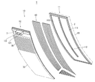
- FIG. 1 is a perspective view of a heat exchanger for an aircraft engine according to the present embodiment.
- FIG. 2 is a cross-sectional view taken along the line II-II in FIG.
- FIG. 3 is an exploded perspective view of the heat exchanger shown in FIG.
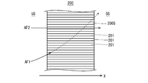
- FIG. 4 is a plan view of a heat exchanger in which radiating fins extend along the rotation axis.
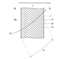
- FIG. 5 is a plan view of the heat exchanger shown in FIG.
- the heat exchanger according to the present embodiment can be arranged on a curved surface of an aircraft engine in an aircraft engine including a fan.
- the heat exchanger includes a main body and a plurality of first radiating fins.
- the main body includes a flow path through which a fluid can flow.
- the main body further has a back surface facing the curved surface and a surface opposite to the back surface, and is curved corresponding to the curved surface.
- the plurality of first radiating fins are arranged on the surface of the main body and extend so as to intersect the rotation axis of the aircraft engine.
- an airflow passing through a fan turns into a swirling flow and crosses the rotation axis.
- the plurality of first radiating fins extend so as to intersect the rotation axis, and thus a swirl flow easily flows between the plurality of first radiating fins. Therefore, the heat exchange rate is improved.
- the first heat dissipating fins extend along a swirling flow that flows on the surface.
- the swirl flow is more likely to flow between the plurality of first radiation fins. Therefore, the heat exchange rate is improved.
- At least the upstream end may extend along the swirling flow.
- the swirl flow easily flows between the plurality of first heat radiation fins.
- the above-described heat exchanger may further include a plurality of second radiating fins arranged on the back surface and extending so as to intersect the rotation axis.
- the second radiating fin extends along a swirling flow.
- the swirl flow is more likely to flow between the plurality of second radiating fins.
- At least the upstream end may extend along the swirling flow.
- the swirl flow is likely to flow between the plurality of second radiating fins.
- FIG. 1 is a perspective view of a heat exchanger for an aircraft engine according to the present embodiment.
- the heat exchanger 1 of this embodiment is arrange
- the aircraft engine is, for example, a turbofan engine.
- the curved surface of the aircraft engine is, for example, the inner peripheral surface of the fan casing, the outer peripheral surface of the engine core casing, or the like.
- positioned at the internal peripheral surface of a fan casing is illustrated.
- the heat exchanger of the present embodiment may be disposed on a curved surface of an engine member other than the fan casing and the engine core casing.
- positioning location of the heat exchanger in a curved surface will not be restrict
- the heat exchanger may be disposed on the curved surface on the upstream side of the fan, or may be disposed on the curved surface on the downstream side of the fan.
- a swirling flow is generated both upstream and downstream of the fan.
- the heat exchanger 1 is a so-called surface-type heat exchanger that has a bow-like plate shape. In the aircraft engine, the heat exchanger 1 is curved corresponding to a curved surface (not shown).
- the X axis in FIG. 1 indicates the direction of the rotational axis of an aircraft engine (not shown).
- the length of the heat exchanger 1 shown in FIG. 1 is about 1/8 of the circumferential length at the location of the curved surface of the aircraft engine.
- the length of the heat exchanger 1 is not particularly limited.
- the heat exchanger 1 may be, for example, an annular shape extending in the entire circumferential direction at the place where the curved surface of the fan casing is disposed.
- FIG. 1 is a cross-sectional view taken along the line II-II in FIG.
- the heat exchanger 1 includes a main body 10 having a front surface 2 and a back surface 3.
- the back surface 3 faces the curved surface of the aircraft engine (in this example, the inner peripheral surface of the fan casing).
- the front surface 2 is disposed on the side opposite to the back surface 3.
- a plurality of heat radiation fins 20 and 30 are arranged on the front surface 2 and the back surface 3.
- the plurality of heat radiation fins 20 are erected on the surface 2.
- the plurality of radiating fins 20 are arranged in a direction substantially perpendicular to the extending direction of the radiating fins 20.
- the plurality of radiating fins 30 are erected on the back surface 3 and arranged in a direction perpendicular to the extending direction of the radiating fins 30. 1 to 3, a region where a plurality of heat radiation fins 20 and 30 are arranged is indicated by an alternate long and short dash line, and some of the heat radiation fins 20 and 30 are not shown.
- FIG. 3 is an exploded perspective view of the heat exchanger 1.
- the main body 10 includes a plate-like front member 11 and a plate-like back member 12.
- the main body 10 is made of, for example, aluminum or an aluminum alloy.
- the material of the main body 10 may also be stainless steel, titanium, copper, Inconel (trademark) or the like.
- the front member 11 and the back member 12 are overlapped in the thickness direction to form a casing-shaped main body 10.
- a plurality of corrugated fins 40 are disposed in the main body 10.
- the front member 11, the back member 12, and the plate-like fins 40 are joined together by brazing, for example.
- the space in the main body 10 is divided into an outward path 111 and a return path 113 by a partition 112.
- Corrugated fins 40 are disposed in the forward path 111.
- the corrugated fin 40 divides the forward path 111 into a plurality of fine flow paths.
- the corrugated fins 40 are disposed on the return path 113, and the return path 113 is partitioned into a plurality of fine flow paths.
- the forward path 111 and the return path 113 are connected in the main body 10 to form a flow path of the target fluid.
- the back member 12 has an inflow port 121 and an outflow port 122 on the back surface 3.
- the target fluid flows into the heat exchanger 1 from the inlet 121.
- the target fluid is distributed to fine flow paths partitioned by the corrugated fins 40 and flows through the main body 10 in the order of the forward path 111 and the return path 113.
- heat exchange is performed between the target fluid in the main body 10 and the external airflow via the corrugated fins 40 and the heat radiating fins 20 and 30, and the target fluid is cooled.
- the cooled target fluid flows out of the heat exchanger 1 from the outlet 122 and returns to a device (an engine core, a generator, or the like) in which the target fluid is used.
- the heat radiating fins 20 extend so as to intersect the rotation axis X of the aircraft engine. More specifically, the radiating fin 20 extends along a swirl flow AF1 that flows on a curved surface of the aircraft engine on which the heat exchanger 1 is disposed.
- the airflow flowing through the aircraft engine is not always parallel to the direction of the aircraft engine's rotation axis.
- the airflow turns into a swirl flow when passing through the fan. That is, on the downstream side of the fan, the airflow (swirl flow) swirls by the fan and flows across the rotation axis X.
- the swirl flow AF1 flows intersecting the rotation axis X. Therefore, the swirl flow AF ⁇ b> 1 collides with the heat radiation fin 201 at the end portion on the upstream side US of the heat radiation fin 201. In this case, the swirl flow AF1 changes the flow direction and easily flows out from between the plurality of adjacent radiation fins 201 to the outside (for example, above the radiation fins 201).
- the swirl flow AF1 is difficult to flow over the entire length of the radiating fin 201. Therefore, compared with the case where airflow AF2 flows on the heat exchanger 200, a heat exchange rate falls.
- the radiating fin 20 extends so as to intersect the rotation axis X. More specifically, the radiating fins 20 extend along a swirling flow that passes on a curved surface on which the heat exchanger 1 is disposed. In this case, as shown in FIG. 5, the swirl flow AF ⁇ b> 1 tends to flow along the radiating fin 20 over the entire length of the radiating fin 20. Therefore, compared with the radiation fin 201 shown in FIG.
- the direction in which the swirl flow is different in each area of the curved surface of the aircraft engine.
- the direction of the swirling flow in each region of the curved surface can be easily obtained by simulation or the like. Therefore, for example, the flow of the swirling flow on the curved surface on which the heat exchanger 1 is disposed can be analyzed by simulation, and the extending direction of the radiation fins 20 can be determined based on the swirling flow obtained by the analysis. .
- the heat radiation fin 20 It is only necessary for the heat radiation fin 20 to extend along the heat radiation fin at least at the upstream end (the portion of the heat radiation fin 20 in FIG. 5 that corresponds to the region 20U). In this case, the swirl flow AF1 tends to flow between the adjacent heat radiating fins 20. Therefore, the swirl flow AF1 tends to flow between the adjacent radiating fins 20.
- the fact that the radiating fin 20 extends along the swirl flow AF1 is not only the case where the radiating fin 20 extends in parallel with the swirl flow AF1, but for example, the radiating fin 20 and the swirl flow AF1 are ⁇ Including the case of crossing within 15 °.
- the end portion on the upstream side US of the radiating fin 20 means a range of L0 / 10 from at least the upstream end of the radiating fin 20 when the entire length of the radiating fin 20 is L0 ( (See FIG. 5).
- the radiating fins 30 arranged on the back surface 3 also extend so as to intersect the rotation axis X, similarly to the radiating fins 20. More specifically, the radiating fins 30 extend along a swirling flow that flows on the curved surface of the aircraft engine in which the heat exchanger 1 is disposed. In this case, similarly to the radiation fins 20, the swirl flow AF1 easily flows between the adjacent radiation fins 30, and the heat exchange rate is increased.
- the heat exchanger 1 includes the radiation fins 30 on the back surface 3.
- the heat exchanger 1 may not include the radiation fins 30.
- the radiating fins 30 may extend along the rotation axis X without crossing the rotation axis X.
- the radiating fin 20 extends curvedly on the surface 2 along the swirl flow.
- the heat radiating fins 20 may extend linearly.
- the heat radiation fins 20 and 30 can be manufactured by cutting, precision casting, additive manufacturing, or the like.
Landscapes
- Engineering & Computer Science (AREA)
- Physics & Mathematics (AREA)
- Mechanical Engineering (AREA)
- General Engineering & Computer Science (AREA)
- Thermal Sciences (AREA)
- Chemical & Material Sciences (AREA)
- Combustion & Propulsion (AREA)
- Geometry (AREA)
- Heat-Exchange Devices With Radiators And Conduit Assemblies (AREA)
Abstract
熱交換率を向上できる航空機エンジン用の熱交換器を提供する。熱交換器(1)は、航空機エンジンの湾曲面に配置される。熱交換器(1)は、本体(10)と、複数の放熱フィン(20)とを備える。本体(10)は、流体が流通可能な流路を内部に含み、湾曲面と対向する裏面(3)と、裏面(3)と反対側の表面(2)とを有し、湾曲面に対応して湾曲している。複数の第1放熱フィン(20)は、本体(10)の表面に配列され、航空機エンジンの回転軸(X)に対して交差して延びる。
Description
本発明は、熱交換器に関し、さらに詳しくは、航空機エンジン用の熱交換器に関する。
ガスタービンエンジンに代表される航空機エンジンには、熱交換器が搭載される。航空機エンジン用の熱交換器は、航空機エンジンの潤滑油の冷却や、航空機エンジンに搭載された発電機の潤滑油の冷却に利用される。航空機エンジン用の熱交換器には、プレートフィン型、シェルアンドチューブ型、及び、サーフェス型等がある。
これらの熱交換器のうち、サーフェス型の熱交換器は、他の熱交換器と比較してコンパクト化できる。このようなサーフェス型の熱交換器はたとえば、特開2008-144752(特許文献1)及び特許第5442916号(特許文献2)に提案されている。
特許文献1及び特許文献2に開示された熱交換器は弓なりに湾曲した板状である。熱交換器は、航空機エンジンの湾曲面に沿って配置される。航空機エンジンの湾曲面はたとえば、ファンケースの内周面や、エンジンコアケーシングの外周面等である。サーフェス型熱交換器の湾曲形状は、熱交換機が配置される箇所の湾曲面の形状と対応する。
サーフェス型熱交換器の表面は、航空機エンジン内を通過する気流に曝される。サーフェス型熱交換器の表面には、複数の放熱フィンが配置される。複数の放熱フィンは、航空機エンジンの回転軸方向に延び、航空機エンジンの周方向に配列される。さらに、熱交換器の内部には、流路が形成されている。
上述の潤滑油等の流体(以下、対象流体という)は、サーフェス型熱交換器内に流入し、内部の流路を流れる。サーフェス型熱交換器の表面の複数の放熱フィンは、気流に曝される。そのため、流路中の対象流体の熱が、放熱フィンを介して外部に放出される。冷却された対象流体は、熱交換器から外部に流出し、利用される装置(発電機等)に戻る。
上述のとおり、サーフェス型熱交換器は、航空機エンジンの任意の箇所に、エンジンの湾曲面に沿って配置される。そのため、他の熱交換器と比較して、エンジン内を流れる気流の抵抗が低減される。
サーフェス型熱交換器において、表面に配列された複数の放熱フィンは、上述のとおり、航空機エンジンの回転軸に沿って延びる。上記特許文献1及び2に開示されたサーフェス型熱交換器の放熱フィンも、航空機エンジンの回転軸に沿って延びている。この場合、放熱フィンに流れる気流が回転軸に沿って流れていれば、熱交換率が最も高まる。しかしながら、航空機エンジンでは、気流がファンを通過すると旋回流になる。旋回流は、回転軸に沿って流れず、回転軸と交差して流れる。したがって、放熱フィンの延在方向は気流(旋回流)の流れと交差する。この場合、熱交換率が高まりにくい。
本発明の目的は、熱交換率を向上できる、熱交換器を提供することである。
本実施形態による熱交換器は、ファンを備える航空機エンジンにおいて、航空機エンジンの湾曲面に配置可能である。上記熱交換器は、本体と、複数の第1放熱フィンとを備える。本体は、流体が流通可能な流路を内部に含む。本体はさらに、湾曲面と対向する裏面と、裏面と反対側の表面とを有し、湾曲面に対応して湾曲している。複数の第1放熱フィンは、本体の表面に配列され、航空機エンジンの回転軸に対して交差して延びる。
本実施形態の熱交換器は、熱交換率を向上できる。
本実施形態による熱交換器は、ファンを備える航空機エンジンにおいて、航空機エンジンの湾曲面に配置可能である。上記熱交換器は、本体と、複数の第1放熱フィンとを備える。本体は、流体が流通可能な流路を内部に含む。本体はさらに、湾曲面と対向する裏面と、裏面と反対側の表面とを有し、湾曲面に対応して湾曲する。複数の第1放熱フィンは、本体の表面に配列され、航空機エンジンの回転軸に対して交差して延びる。
航空機エンジンにおいて、たとえば、ファンを通った気流は、旋回流となり、回転軸に対して交差して流れる。上述のとおり、複数の第1放熱フィンは、回転軸に対して交差して延びるため、複数の第1放熱フィンの間に旋回流が流れやすい。そのため、熱交換率が向上する。
好ましくは、第1放熱フィンは、表面を流れる旋回流に沿って延びる。
この場合、複数の第1放熱フィンの間に旋回流がさらに流れやすい。そのため、熱交換率が向上する。
第1放熱フィンのうち、少なくとも上流側の端部は、旋回流に沿って延びてもよい。
この場合、旋回流が複数の第1放熱フィンの間に流入しやすくなる。
上述の熱交換器はさらに、裏面に配列され回転軸に対して交差して延びる複数の第2放熱フィンを備えてもよい。
この場合、裏面においても、第2放熱フィンが回転軸に対して交差しているため、複数の第2放熱フィンの間に旋回流が流れやすい。
好ましくは、第2放熱フィンは、旋回流に沿って延びる。
この場合、複数の第2放熱フィンの間に旋回流がさらに流れやすい。
第2放熱フィンのうち、少なくとも上流側の端部が、旋回流に沿って延びてもよい。
この場合、旋回流が複数の第2放熱フィンの間に流入しやすくなる。
以下、本実施形態の熱交換器の詳細について、図面を参照して説明する。図中同一又は相当する部分には同一符号を付してその説明は繰り返さない。
[熱交換器の全体構成]
図1は、本実施の形態による航空機エンジン用の熱交換器の斜視図である。本実施形態の熱交換器1は、ファンを備える航空機エンジン(図示せず)に配置される。より具体的には、熱交換器1は、航空機エンジンの湾曲面に沿って配置される。
図1は、本実施の形態による航空機エンジン用の熱交換器の斜視図である。本実施形態の熱交換器1は、ファンを備える航空機エンジン(図示せず)に配置される。より具体的には、熱交換器1は、航空機エンジンの湾曲面に沿って配置される。
航空機エンジンはたとえば、ターボファンエンジンである。航空機エンジンの湾曲面はたとえば、ファンケーシングの内周面や、エンジンコアケーシングの外周面等である。図1では、ファンケーシングの内周面に配置される熱交換器を例示する。しかしながら、本実施形態の熱交換器は、ファンケーシング及びエンジンコアケーシング以外の他のエンジン部材の湾曲面に配置されてもよい。湾曲面における熱交換器の配置箇所は、気流が存在する場所であれば、特に制限されない。熱交換器は、ファンの上流側の湾曲面に配置されてもよいし、ファンの下流側の湾曲面に配置されてもよい。旋回流は、ファンの上流側でも下流側でも発生する。
図1を参照して、熱交換器1は弓なりに湾曲した板状であり、いわゆるサーフェス型の熱交換器である。航空機エンジン内において、熱交換器1は、配置される湾曲面(図示せず)に対応して湾曲している。
図1中のX軸は、図示しない航空機エンジンの回転軸方向を示す。図1に示す熱交換器1の長さは、航空機エンジンの湾曲面の配置箇所における周方向長さの1/8程度である。しかしながら、熱交換器1の長さは特に限定されない。熱交換器1はたとえば、ファンケーシングの湾曲面の配置箇所における円周方向全長に延びた、円環状であってもよい。
図1において、熱交換器1の左側が気流の上流側USであり、右側が気流の下流側DSである。熱交換器1は、冷却対象となる流体(以下、対象流体という)を内部に通し、対象流体を冷却する。図2は、図1中のII-II面での断面図である。図1及び図2を参照して、熱交換器1は、表面2と、裏面3とを有する本体10を備える。裏面3は、航空機エンジンの湾曲面(本例ではファンケーシングの内周面)と対向する。表面2は、裏面3と反対側に配置される。
表面2及び裏面3には、複数の放熱フィン20及び30が配列される。複数の放熱フィン20は、表面2上に立てられている。複数の放熱フィン20は、放熱フィン20の延在方向と略垂直な方向に配列される。同様に、複数の放熱フィン30は裏面3上に立てられ、放熱フィン30の延在方向と垂直な方向に配列される。図1~図3において、複数の放熱フィン20及び30が配列された領域は一点鎖線で示され、一部の放熱フィン20及び30の図示は省略されている。
図3は、熱交換器1の分解斜視図である。本体10は、板状の表部材11と、板状の裏部材12とを備える。本体10はたとえば、アルミニウム又はアルミニウム合金製である。本体10の材質はまた、ステンレス鋼、チタン、銅、インコネル(商標)等であってもよい。
表部材11と裏部材12とが板厚方向に重ね合わされ、筐体状の本体10となる。本体10内には、複数のコルゲートフィン40が配置される。表部材11、裏部材12及び板状フィン40はたとえば、ろう付により互いに接合される。
本体10内の空間は、仕切112により、往路111と復路113とに区画される。往路111内には、コルゲートフィン40が配置される。コルゲートフィン40により、往路111は複数の微細な流路に区画される。同様に、復路113にもコルゲートフィン40が配置され、復路113は複数の微細な流路に区画される。往路111と復路113とは本体10内で連結しており、対象流体の流路を形成する。
裏部材12は、流入口121と流出口122とを裏面3に有する。対象流体は、流入口121から熱交換器1内に流入する。対象流体は、コルゲートフィン40により区画された微細な流路に分配され、往路111、復路113の順に、本体10内を流れる。このとき、コルゲートフィン40、放熱フィン20及び30を介して、本体10内の対象流体と外部の気流とで熱交換が行われ、対象流体が冷却される。冷却された対象流体は、流出口122から熱交換器1の外部に流出して、対象流体が利用される装置(エンジンコアや発電機等)に戻る。
[放熱フィン20]
図1を参照して、放熱フィン20は、航空機エンジンの回転軸Xに対して交差して延びる。より具体的には、放熱フィン20は、航空機エンジンの湾曲面のうち、熱交換器1が配置される湾曲面上を流れる旋回流AF1に沿って延びる。
図1を参照して、放熱フィン20は、航空機エンジンの回転軸Xに対して交差して延びる。より具体的には、放熱フィン20は、航空機エンジンの湾曲面のうち、熱交換器1が配置される湾曲面上を流れる旋回流AF1に沿って延びる。
航空機エンジンに流れる気流は、航空機エンジンの回転軸方向に対してかならずしも平行ではない。特にターボファンエンジンのように、ファンを備える航空機エンジンの場合、気流はファンを通過すると旋回流になる。つまり、ファンよりも下流側では、気流(旋回流)はファンにより旋回し、回転軸Xと交差して流れる。
図4に示すように、熱交換器200の表面200S上に配列された複数の放熱フィン201が、回転軸Xに沿って延びている場合を想定する。図中のAF2のように、気流が回転軸Xに沿って流れれば、気流AF2は放熱フィン201の全長にわたって流れる。したがってこの場合、放熱フィン201と接触する空気流量は大きく、熱交換率は高い。
一方、気流がAF1のように旋回流であれば、旋回流AF1は回転軸Xに対して交差して流れる。そのため、旋回流AF1は放熱フィン201の上流側USの端部で放熱フィン201とぶつかる。この場合、旋回流AF1は流れの向きを変え、隣り合う複数の放熱フィン201の間から外部(たとえば、放熱フィン201の上方)に流出しやすい。
要するに、旋回流AF1は、放熱フィン201の全長にわたって流れにくい。そのため、熱交換器200上を気流AF2が流れる場合と比較して、熱交換率が低下する。
上述のとおり、放熱フィン20が回転軸Xに対して交差して延びる。より具体的には、放熱フィン20は、熱交換器1が配置される湾曲面上を通過する旋回流に沿って延びる。この場合、図5に示すとおり、旋回流AF1は放熱フィン20に沿って、放熱フィン20全長にわたって流れやすい。そのため、図4に示す放熱フィン201と比較して、熱交換率が高まる。
旋回流の流れる方向は、航空機エンジンの湾曲面の各領域で異なる。しかしながら、航空機エンジンの仕様(湾曲面の形状、ファンのサイズ及び形状等)に基づいて、シミュレーション等により、湾曲面の各領域での旋回流の流れる方向は容易に求められる。したがって、たとえば、熱交換器1が配置される湾曲面上の旋回流の流れをシミュレーションにより解析し、その解析により得られた旋回流の流れに基づいて、放熱フィン20の延在方向を決定できる。
放熱フィン20は、少なくとも上流側の端部(図5中の放熱フィン20のうち、領域20Uの部分)が放熱フィンに沿って延びていればよい。この場合、旋回流AF1は、隣り合う放熱フィン20の間に流入しやすい。そのため、旋回流AF1は隣り合う放熱フィン20の間を流れやすい。
本実施形態において、放熱フィン20が旋回流AF1に沿って延びているとは、放熱フィン20が旋回流AF1と平行に延びる場合だけでなく、たとえば、放熱フィン20と旋回流AF1とが、±15°以内で交差する場合も含む。
また、本明細書において、放熱フィン20の上流側USの端部とは、放熱フィン20の全長をL0とした場合、少なくとも放熱フィン20の上流側の端からL0/10の範囲を意味する(図5参照)。
[放熱フィン30]
図3を参照して、好ましくは、裏面3に配置される放熱フィン30も、放熱フィン20と同様に、回転軸Xに対して交差して延びる。より具体的には、放熱フィン30は、熱交換器1が配置される航空機エンジンの湾曲面上に流れる旋回流に沿って延びる。この場合、放熱フィン20と同様に、旋回流AF1が隣り合う放熱フィン30の間に流れやすくなり、熱交換率が高まる。
図3を参照して、好ましくは、裏面3に配置される放熱フィン30も、放熱フィン20と同様に、回転軸Xに対して交差して延びる。より具体的には、放熱フィン30は、熱交換器1が配置される航空機エンジンの湾曲面上に流れる旋回流に沿って延びる。この場合、放熱フィン20と同様に、旋回流AF1が隣り合う放熱フィン30の間に流れやすくなり、熱交換率が高まる。
少なくとも放熱フィン30の上流側USの端部が、旋回流に沿って延びていれば、上述の効果がある程度得られる。
上述の実施の形態では、熱交換器1は、裏面3に放熱フィン30を備える。しかしながら、熱交換器1は放熱フィン30を備えなくてもよい。また、放熱フィン30は、回転軸Xに対して交差して延びずに、回転軸Xに沿って延びていてもよい。
図5では、放熱フィン20は、旋回流に沿って表面2上を湾曲して延びる。しかしながら、放熱フィン20は直線状に延びてもよい。また、放熱フィン20及び30は切削、精密鋳造、積層造形等により製作することができる。
以上、本発明の実施の形態を説明した。しかしながら、上述した実施の形態は本発明を実施するための例示に過ぎない。したがって、本発明は上述した実施の形態に限定されることなく、その趣旨を逸脱しない範囲内で上述した実施の形態を適宜変形して実施することが可能である。
1,200 熱交換器
2,200S 表面
3 裏面
10 本体
20,30,201 放熱フィン
AF1 旋回流
2,200S 表面
3 裏面
10 本体
20,30,201 放熱フィン
AF1 旋回流
Claims (6)
- ファンを備える航空機エンジンにおいて、前記航空機エンジンの湾曲面に配置可能な、航空機エンジン用の熱交換器であって、
流体が流通可能な流路を内部に含み、前記湾曲面と対向する裏面と、前記裏面と反対側の表面とを有し、前記湾曲面に対応して湾曲している本体と、
前記本体の前記表面に配列され、前記航空機エンジンの回転軸に対して交差して延びる複数の第1放熱フィンとを備える、熱交換器。 - 請求項1に記載の熱交換器であって、
前記第1放熱フィンは、前記表面上を流れる旋回流に沿って延びる、熱交換器。 - 請求項1に記載の熱交換器であって、
前記第1放熱フィンのうち、少なくとも上流側の端部が、前記表面を流れる旋回流に沿って延びる、熱交換器。 - 請求項1~請求項3のいずれか1項に記載の熱交換器であってさらに、
前記裏面に配列され、前記回転軸に対して交差して延びる複数の第2放熱フィンを備える、熱交換器。 - 請求項4に記載の熱交換器であって、
前記第2放熱フィンは、前記裏面を流れる旋回流に沿って延びる、熱交換器。 - 請求項4に記載の熱交換器であって、
前記第2放熱フィンのうち、少なくとも上流側の端部が、前記裏面を流れる旋回流に沿って延びる、熱交換器。
Priority Applications (5)
| Application Number | Priority Date | Filing Date | Title |
|---|---|---|---|
| PCT/JP2014/005343 WO2016063312A1 (ja) | 2014-10-21 | 2014-10-21 | 航空機エンジン用の熱交換器 |
| PCT/JP2015/005193 WO2016063497A1 (ja) | 2014-10-21 | 2015-10-14 | 航空機エンジン用の熱交換器 |
| US15/507,450 US10156404B2 (en) | 2014-10-21 | 2015-10-14 | Heat exchanger for aircraft engine |
| EP15853102.0A EP3176530B1 (en) | 2014-10-21 | 2015-10-14 | Heat exchanger for aircraft engine |
| JP2016555072A JP6099842B2 (ja) | 2014-10-21 | 2015-10-14 | 航空機エンジン用の熱交換器 |
Applications Claiming Priority (1)
| Application Number | Priority Date | Filing Date | Title |
|---|---|---|---|
| PCT/JP2014/005343 WO2016063312A1 (ja) | 2014-10-21 | 2014-10-21 | 航空機エンジン用の熱交換器 |
Publications (1)
| Publication Number | Publication Date |
|---|---|
| WO2016063312A1 true WO2016063312A1 (ja) | 2016-04-28 |
Family
ID=55760388
Family Applications (2)
| Application Number | Title | Priority Date | Filing Date |
|---|---|---|---|
| PCT/JP2014/005343 Ceased WO2016063312A1 (ja) | 2014-10-21 | 2014-10-21 | 航空機エンジン用の熱交換器 |
| PCT/JP2015/005193 Ceased WO2016063497A1 (ja) | 2014-10-21 | 2015-10-14 | 航空機エンジン用の熱交換器 |
Family Applications After (1)
| Application Number | Title | Priority Date | Filing Date |
|---|---|---|---|
| PCT/JP2015/005193 Ceased WO2016063497A1 (ja) | 2014-10-21 | 2015-10-14 | 航空機エンジン用の熱交換器 |
Country Status (4)
| Country | Link |
|---|---|
| US (1) | US10156404B2 (ja) |
| EP (1) | EP3176530B1 (ja) |
| JP (1) | JP6099842B2 (ja) |
| WO (2) | WO2016063312A1 (ja) |
Cited By (1)
| Publication number | Priority date | Publication date | Assignee | Title |
|---|---|---|---|---|
| JP2020008205A (ja) * | 2018-07-05 | 2020-01-16 | 住友精密工業株式会社 | 熱交換器および熱交換器の製造方法 |
Families Citing this family (15)
| Publication number | Priority date | Publication date | Assignee | Title |
|---|---|---|---|---|
| EP3148828A1 (en) * | 2014-05-28 | 2017-04-05 | RBC Green Energy II, LLC | Air-cooled heat exchange system |
| US10823067B2 (en) | 2016-05-11 | 2020-11-03 | General Electric Company | System for a surface cooler with OGV oriented fin angles |
| US20180328285A1 (en) * | 2017-05-11 | 2018-11-15 | Unison Industries, Llc | Heat exchanger |
| JP6549268B1 (ja) * | 2018-03-05 | 2019-07-24 | 住友精密工業株式会社 | 航空機エンジン用の熱交換器 |
| JP6371929B1 (ja) * | 2018-03-08 | 2018-08-08 | 住友精密工業株式会社 | 熱交換器システム |
| US11035626B2 (en) * | 2018-09-10 | 2021-06-15 | Hamilton Sunstrand Corporation | Heat exchanger with enhanced end sheet heat transfer |
| BE1026919B1 (fr) * | 2018-12-24 | 2020-07-24 | Safran Aero Boosters Sa | Échangeur de chaleur air-huile |
| BE1027057B1 (fr) * | 2019-02-18 | 2020-09-14 | Safran Aero Boosters Sa | Échangeur de chaleur air-huile |
| US11412640B2 (en) | 2019-07-29 | 2022-08-09 | Pratt & Whitney Canada Corp. | Plate cooler for aircraft electronic components |
| US11414202B2 (en) | 2019-11-06 | 2022-08-16 | Pratt & Whitney Canada Corp. | Plate cooler for aircraft electronic components |
| CN113382608B (zh) * | 2021-06-09 | 2022-11-08 | 北京机电工程研究所 | 一种飞行器设备舱散热系统及其散热方法 |
| US12298080B2 (en) | 2022-02-10 | 2025-05-13 | Rtx Corporation | Conformal heat exchanger |
| US12209819B2 (en) | 2022-06-03 | 2025-01-28 | Rtx Corporation | Conformal heat exchanger |
| FR3155863B1 (fr) * | 2023-11-27 | 2026-01-09 | Safran Nacelles | Echangeur de chaleur surfacique comprenant un réducteur de pertes de charge et nacelle d’aéronef équipée d’un tel échangeur de chaleur |
| US12510023B1 (en) * | 2024-07-01 | 2025-12-30 | Rtx Corporation | Fan case mounted evaporator for aircraft turbine engine |
Citations (3)
| Publication number | Priority date | Publication date | Assignee | Title |
|---|---|---|---|---|
| JPH03225117A (ja) * | 1989-12-22 | 1991-10-04 | Hitachi Ltd | 燃焼装置及びその燃焼方法 |
| JP2003130354A (ja) * | 2001-10-18 | 2003-05-08 | Mitsubishi Heavy Ind Ltd | ガスタービン燃焼器のプレートフィン構造及びガスタービン燃焼器 |
| JP5442916B1 (ja) * | 2013-06-26 | 2014-03-19 | 住友精密工業株式会社 | 航空機用エンジンの熱交換器 |
Family Cites Families (7)
| Publication number | Priority date | Publication date | Assignee | Title |
|---|---|---|---|---|
| JPS59229193A (ja) * | 1983-06-10 | 1984-12-22 | Hitachi Ltd | 熱交換器 |
| US5484122A (en) * | 1993-11-09 | 1996-01-16 | Parker-Hannifin Corporation | Turbine exhaust gas anti-ice system |
| JP2002155758A (ja) | 2000-11-22 | 2002-05-31 | Mitsubishi Heavy Ind Ltd | 冷却構造及びそれを用いた燃焼器 |
| US8387362B2 (en) * | 2006-10-19 | 2013-03-05 | Michael Ralph Storage | Method and apparatus for operating gas turbine engine heat exchangers |
| EP2075194B1 (fr) * | 2007-12-27 | 2017-08-16 | Techspace Aero | Echangeur de chaleur air-huile pour turboréacteur, turboréacteur associé et utilisation dudit échangeur |
| EP2339123B1 (fr) * | 2009-12-23 | 2013-07-10 | Techspace Aero S.A. | Paroi intérieure annulaire de la veine secondaire d'un turboréacteur et procédé d'assemblage d'une telle paroi |
| US20140044525A1 (en) * | 2012-08-07 | 2014-02-13 | Unison Industries, Llc | Gas turbine engine heat exchangers and methods of assembling the same |
-
2014
- 2014-10-21 WO PCT/JP2014/005343 patent/WO2016063312A1/ja not_active Ceased
-
2015
- 2015-10-14 JP JP2016555072A patent/JP6099842B2/ja active Active
- 2015-10-14 EP EP15853102.0A patent/EP3176530B1/en active Active
- 2015-10-14 US US15/507,450 patent/US10156404B2/en active Active
- 2015-10-14 WO PCT/JP2015/005193 patent/WO2016063497A1/ja not_active Ceased
Patent Citations (3)
| Publication number | Priority date | Publication date | Assignee | Title |
|---|---|---|---|---|
| JPH03225117A (ja) * | 1989-12-22 | 1991-10-04 | Hitachi Ltd | 燃焼装置及びその燃焼方法 |
| JP2003130354A (ja) * | 2001-10-18 | 2003-05-08 | Mitsubishi Heavy Ind Ltd | ガスタービン燃焼器のプレートフィン構造及びガスタービン燃焼器 |
| JP5442916B1 (ja) * | 2013-06-26 | 2014-03-19 | 住友精密工業株式会社 | 航空機用エンジンの熱交換器 |
Cited By (2)
| Publication number | Priority date | Publication date | Assignee | Title |
|---|---|---|---|---|
| JP2020008205A (ja) * | 2018-07-05 | 2020-01-16 | 住友精密工業株式会社 | 熱交換器および熱交換器の製造方法 |
| JP7094805B2 (ja) | 2018-07-05 | 2022-07-04 | 住友精密工業株式会社 | 熱交換器および熱交換器の製造方法 |
Also Published As
| Publication number | Publication date |
|---|---|
| US20170284750A1 (en) | 2017-10-05 |
| EP3176530A4 (en) | 2018-04-18 |
| WO2016063497A1 (ja) | 2016-04-28 |
| JPWO2016063497A1 (ja) | 2017-04-27 |
| EP3176530A1 (en) | 2017-06-07 |
| JP6099842B2 (ja) | 2017-03-22 |
| US10156404B2 (en) | 2018-12-18 |
| EP3176530B1 (en) | 2019-07-17 |
Similar Documents
| Publication | Publication Date | Title |
|---|---|---|
| WO2016063312A1 (ja) | 航空機エンジン用の熱交換器 | |
| JP6865528B2 (ja) | クロスフロー導管熱交換器内の管 | |
| JP6303755B2 (ja) | 排気熱交換器 | |
| JP6216118B2 (ja) | 熱交換器 | |
| US20150218997A1 (en) | Exhaust Heat Recovery Device | |
| EP2853851B1 (en) | Heat exchanger thermal fatigue stress reduction | |
| JP5967300B2 (ja) | 熱交換器 | |
| US20150047820A1 (en) | Bendable heat exchanger | |
| JP2016521842A (ja) | 車両のための熱交換器 | |
| JP2010027963A (ja) | 冷却器 | |
| CN112368535B (zh) | 热交换器 | |
| JP2014051981A (ja) | ノズル端壁の蛇行冷却 | |
| US20130183140A1 (en) | Fan shroud with cooling passage | |
| WO2016063311A1 (ja) | 航空機エンジン用の熱交換器 | |
| JP6577282B2 (ja) | 熱交換器 | |
| JP6687649B2 (ja) | 排気熱回収装置 | |
| US12104534B2 (en) | Heat exchanger for aircraft engine | |
| JP5747783B2 (ja) | 熱交換器 | |
| ES3037762T3 (en) | Heat exchanger | |
| JP2013068131A (ja) | スワールプレート | |
| GB2519407A (en) | Bendable heat exchanger | |
| JP2013152057A (ja) | 熱交換器 | |
| JP2017141755A5 (ja) | ||
| JP2017141753A5 (ja) | ||
| JP2001020739A (ja) | 建設機械の冷却装置 |
Legal Events
| Date | Code | Title | Description |
|---|---|---|---|
| 121 | Ep: the epo has been informed by wipo that ep was designated in this application |
Ref document number: 14904469 Country of ref document: EP Kind code of ref document: A1 |
|
| NENP | Non-entry into the national phase |
Ref country code: DE |
|
| NENP | Non-entry into the national phase |
Ref country code: JP |
|
| 122 | Ep: pct application non-entry in european phase |
Ref document number: 14904469 Country of ref document: EP Kind code of ref document: A1 |