WO2016059778A1 - 送風装置 - Google Patents
送風装置 Download PDFInfo
- Publication number
- WO2016059778A1 WO2016059778A1 PCT/JP2015/005108 JP2015005108W WO2016059778A1 WO 2016059778 A1 WO2016059778 A1 WO 2016059778A1 JP 2015005108 W JP2015005108 W JP 2015005108W WO 2016059778 A1 WO2016059778 A1 WO 2016059778A1
- Authority
- WO
- WIPO (PCT)
- Prior art keywords
- blower
- air flow
- outlet
- duct
- air
- Prior art date
- Legal status (The legal status is an assumption and is not a legal conclusion. Google has not performed a legal analysis and makes no representation as to the accuracy of the status listed.)
- Ceased
Links
Images






Classifications
-
- B—PERFORMING OPERATIONS; TRANSPORTING
- B60—VEHICLES IN GENERAL
- B60H—ARRANGEMENTS OF HEATING, COOLING, VENTILATING OR OTHER AIR-TREATING DEVICES SPECIALLY ADAPTED FOR PASSENGER OR GOODS SPACES OF VEHICLES
- B60H1/00—Heating, cooling or ventilating devices
-
- B—PERFORMING OPERATIONS; TRANSPORTING
- B60—VEHICLES IN GENERAL
- B60H—ARRANGEMENTS OF HEATING, COOLING, VENTILATING OR OTHER AIR-TREATING DEVICES SPECIALLY ADAPTED FOR PASSENGER OR GOODS SPACES OF VEHICLES
- B60H1/00—Heating, cooling or ventilating devices
- B60H1/24—Ventilating devices where the heating or cooling is irrelevant
-
- B—PERFORMING OPERATIONS; TRANSPORTING
- B60—VEHICLES IN GENERAL
- B60H—ARRANGEMENTS OF HEATING, COOLING, VENTILATING OR OTHER AIR-TREATING DEVICES SPECIALLY ADAPTED FOR PASSENGER OR GOODS SPACES OF VEHICLES
- B60H1/00—Heating, cooling or ventilating devices
- B60H1/34—Nozzles; Air-diffusers
Definitions
- the present disclosure relates to a blower that supplies an air flow to a cabin of a vehicle.
- an air blower that is provided in a cabin of a vehicle and supplies an air flow to the rear side of the vehicle is known.
- various methods are used to change the direction of the air flow blown from the blower outlet of the blower It is being considered to change.
- Patent Document 1 describes a blower provided in the ceiling of a cabin.
- the air flow blown out from the first air outlet flows along the outer side surface of the duct due to the Coanda effect, and travels toward the vehicle rear side while merging with the surrounding air drawn in.
- the air flow is supplied to the cabin in a state where the flow rate is increased as compared with the case where the air flow is blown out from the first air outlet.
- the air blower described in the following Patent Document 1 includes a second air outlet that blows air downward, apart from the first air outlet.
- a 2nd blower outlet blows off an air flow so that the air which a 1st blower outlet blows out may join from upper direction.
- This blower can change the direction of the air flow in the vehicle front-rear direction by changing the balance of the flow rate of the air flow blown out from each of the first air outlet and the second air outlet.
- the present disclosure has been made in view of such a problem, and an object thereof is to provide a blower capable of simultaneously supplying an air flow having a sufficient flow rate to passengers at different positions in the vehicle front-rear direction. There is.
- a blower that supplies an air flow to a cabin of a vehicle includes a blower that generates an air flow, an air flow that extends in the left-right direction of the vehicle, and is generated by the blower.
- an air outlet that blows out to the rear side of the vehicle.
- a blower outlet has the 1st blower part which is a site
- a 2nd blowing part blows off the 2nd airflow supplied to the 2nd position of a cabin.
- the first blow-out portion blows out the first air flow having a flow velocity larger than that of the second air flow and supplied to the first position on the vehicle rear side of the second position.
- the flow velocity of the air flow blown out by the blower varies depending on the part of the blowout port. That is, the flow rate of the first air flow blown from the first blowing portion that is a portion relatively close to the blower is larger than the second air flow blown from the second blowout portion that is a portion relatively far from the blower. .
- the second air flow having a relatively low flow velocity is directed to the second position on the front side of the vehicle, and the first air flow having a relatively high flow velocity is directed to the first position on the vehicle rear side, so that A sufficient air flow can be supplied.
- FIG. 4 is a cross-sectional view showing a IV-IV cross section of FIG. 3.
- FIG. 5 is a cross-sectional view showing a VV cross section of FIG. 3.
- FIG. 5 is a cross-sectional view showing a VI-VI cross section of FIG. 4.
- the blower 10 is attached to the ceiling VL of the cabin VC of the vehicle VH.
- the blower device 10 includes a blower unit 11, two ducts 12 and 12, and two outer flaps 141 and 141.
- the cabin VC is provided with sheets S1, S2, and S3 in the first to third rows.
- the blower 10 is disposed above the heads of the occupants P1, P2, P3 seated on the seats S1, S2, S3, respectively.
- the front-rear direction, the left-right direction, and the up-down direction refer to the front-rear direction, the left-right direction, and the up-down direction when the occupants P1, P2, P3 face the forward direction of the vehicle VH, respectively.
- the blower unit 11 is a device that generates an air flow, and includes a case 111, a blower 112, and a branch body 113, as shown in FIG.
- the case 111 has an outer shape formed in a substantially cylindrical shape, and is arranged at the center of the cabin VC in the left-right direction.
- a suction port 111 a that communicates the inside and outside of the case 111 is formed at the front end of the case 111.
- a pair of air outlets 111b and 111b communicating with the inside and outside of the case 111 are formed on the left and right side surfaces of the case 111, respectively.
- the blower 112 is an electric blower that generates an air flow, and is accommodated in the case 111.
- the blower 112 has a centrifugal multiblade fan (not shown) inside. As the centrifugal multiblade fan rotates, the air in the cabin VC is sucked in through the suction port 111a of the case 111 and blown out from the blower outlet 112a of the blower 112 to the rear side.
- the branch body 113 is a T-shaped member extending from the front end portion to the rear side, branching left and right in the middle and extending to the rear end portion.
- the branch body 113 is accommodated in the case 111, and the branch channel 113 a is partitioned in the case 111.
- the branch body 113 has a front end connected to the air outlet 112 a of the blower 112 and a rear end connected to the pair of air outlets 111 b and 111 b of the case 111. Thereby, the airflow blown out from the blower outlet 112a of the blower 112 is introduced into the branch flow path 113a, is divided into right and left, and is supplied to the blower outlets 111b and 111b of the case 111.
- the ducts 12 and 12 are provided on both the left and right sides of the blower unit 11, respectively.
- the ducts 12 and 12 are hollow members formed so as to extend linearly from the blower unit 11 side toward the end of the cabin VC in the left-right direction.
- the ends of the ducts 12, 12 on the air blowing unit 11 side are connected to the air outlet 111 b of the case 111. Since the ducts 12 and 12 are formed substantially symmetrically in the left-right direction, the right duct 12 will be described below as an example.
- a slit-like outlet 120 having a longitudinal direction in the left-right direction is formed on the lower surface 127 of the duct 12 and near the front end of the duct 12.
- the blower outlet 120 includes a first blower 121 that is a part near the blower 112 and a second blower 122 that is a part farther from the blower 112 than the first blower 121 in the left-right direction.
- the outlet 120 is a single opening in which the first outlet 121 and the second outlet 122 are connected.
- the outer side flap 141 is a flat plate-like member whose dimensions in the left-right direction are smaller than those of the air outlet 120.
- the outer flap 141 is disposed outside the duct 12 and on the rear side of the second blowing part 122.
- the outer flap 141 is supported at one end on the duct 12 side by a rotating shaft 140 (see FIG. 4) extending substantially horizontally in the left-right direction. Thereby, the outer side flap 141 is rotatable about the rotation axis 140, and can be stopped at an arbitrary position.
- the air outlet 120 is formed in the lower surface 127 of the duct 12 at a portion below the duct internal flow path 128, and communicates with the inside and outside of the duct internal flow path 128. Yes.
- the wall surface of the duct 12 is curved so that the end on the rear side of the air outlet 120 enters the inside of the duct internal flow path 128.
- a throttle channel 125 that communicates with the air outlet 120 is formed between the wall surface 124a and the wall surface 124b of the duct 12 that are spaced apart from each other.
- the throttle channel 125 gradually decreases in cross-sectional area from the inlet 125a toward the outlet 120.
- the cross-sectional area of the first communication part 1251 (see FIG. 4) communicating with the first blowing part 121 is the same as that of the second communication part 1252 (see FIG. 5) communicating with the second blowing part 122. It is smaller than the cross-sectional area.
- the guide vane 126 includes three first guide vanes 1261 disposed near the center of the cabin VC and two second guide vanes 1262 disposed near the end of the cabin VC in the left-right direction.
- Each of the first guide vane 1261 and the second guide vane 1262 is curved so that its rear end portion faces the air blowing unit 11 side and its front end portion faces the inlet 125a side of the throttle channel 125, and is circular in a plan view.
- the first guide vane 1261 has a dimension in the front-rear direction larger than that of the second guide vane 1262. Further, the first guide vane 1261 and the second guide vane 1262 are provided on the upstream side of the air outlet 120 of the duct 12 so that the front ends thereof overlap with the inlet 125a of the throttle channel 125 in a plan view. .
- first guide vane 1261 and the second guide vane 1262 are formed with columnar rotation shafts 133 protruding in the vertical direction at the upper end and the lower end thereof.
- the upper and lower ends of each rotating shaft 133 are supported by the wall surface of the duct internal flow path 128.
- both the first guide vane 1261 and the second guide vane 1262 are rotatable about the respective rotation shafts 133.
- the air flow generated by the blower 112 is introduced into the duct 12 through the air outlet 111b of the case 111.
- the airflow flowing through the duct internal flow path 128 inside the duct 12 has forward and rightward flow velocity components.
- the guide vane 126 when the guide vane 126 is in the state shown in FIG. 6, the air flow flows along the outer surface of the guide vane 126 and loses the flow velocity component in the right direction. Thereby, the direction of the air flow is changed to a direction substantially parallel to the front-rear direction, and is guided to the inlet 125 a of the throttle channel 125.
- the air flow led to the inlet 125a flows through the throttle channel 125 toward the outlet 120, and the flow velocity thereof is increased.
- the air flow in the duct internal flow path 128 flows into the inlet 125a in a direction substantially parallel to the front-rear direction. Therefore, due to inertia, the air flow passes through the throttle flow path 125 while remaining in the direction substantially parallel to the front-rear direction. It is blown out to the rear side. Therefore, the direction of the air flow blown backward from the blower outlet 120 is substantially parallel to the front-rear direction.
- the air flow blown from the blower outlet 120 becomes a first air flow F11 blown from the first blower part 121 and a second air flow F21 blown from the second blower part 122.
- the first air flow F11 and the second air flow F21 blown to the rear side from the air outlet 120 first flow along the lower surface 127 of the duct 12 by the Coanda effect. That is, the lower surface 127 of the duct 12 and the lower surface 141a of the outer flap 141 described later constitute a guide surface GS that flows along the air flow.
- first air flow F11 and the second air flow F21 are blown out from the outlet 120, the surrounding air is drawn in to form secondary air flows F41 and F51.
- the first air flow F11 and the second air flow F21 merge with the secondary air flows F41 and F51, and flow toward the rear side along the lower side surface 127 of the duct 12 while increasing their flow rates.
- the first blow-out part 121 is provided on the blower 112 side which is upstream of the second blow-out part 122 in the duct internal flow path 128. For this reason, compared with the air flow supplied to the 2nd blowing part 122, a pressure loss does not arise easily in the process supplied from the air blower 112 with respect to the air flow supplied to the 1st blowing part 121. FIG. Therefore, the pressure of the air flow supplied to the first blowing unit 121 is higher than the pressure of the air flow supplied to the second blowing unit 122.
- the first guide vane 1261 is larger in dimension in the front-rear direction than the second guide vane 1262.
- the first guide vane 1261 causes more air flow than the second guide vane 1262 to flow along the outer surface thereof and guides it to the first communication portion 1251.
- the first guide vane 1261 acts to increase the pressure of the air flow supplied to the first blowing part 121 higher than the pressure of the air flow supplied to the second blowing part 122.
- the cross-sectional area of the first communication part 1251 communicating with the first blowing part 121 is smaller than the cross-sectional area of the second communication part 1252 communicating with the second blowing part 122. For this reason, the air flow supplied to the first blowing part 121 through the first communication part 1251 has a pressure higher than the air flow passing through the second communication part 1252 and supplied to the second blowing part 122. Rise.
- the flow velocity of the first air flow F11 blown out from the first blow-out portion 121 is increased by increasing the pressure of the air flow supplied to the first blow-out portion 121 of the blow-out opening 120. It becomes larger than the flow velocity of the second air flow F21 blown out from the portion 122.
- the first air flow F ⁇ b> 11 blown to the rear side from the first blowing part 121 of the blower outlet 120 flows along the lower surface 127 of the duct 12 due to the Coanda effect, It further flows to the rear side of the duct 12 in the direction along the lower side surface 127.
- the first air flow F11 flows through a portion near the center of the cabin VC in the left-right direction, and is supplied to a position (first position) where the passenger P3 is present.
- the second air flow F ⁇ b> 21 blown rearward from the second blow-out part 122 of the blow-out opening 120 extends along the lower surface 127 of the duct 12 due to the Coanda effect. Then flow along the lower surface 141a of the outer flap 141.
- the direction of the second air flow F21 is changed to the front side by the outer side flap 141 that inclines so as to extend downward, and is supplied to the position (second position) where the occupant P2 is present.
- the flow velocity of the blown air flow differs depending on the part of the air outlet 120. That is, the first air flow F11 blown out from the first blowing part 121 that is a part relatively close to the blower 112 is the second air flow F21 blown out from the second blowing part 122 that is a part relatively far from the blower 112. It is comprised so that a flow rate may become larger than.
- the occupant P3 directs the second air flow F21 having a relatively small flow velocity toward the position where the occupant P2 is present and the first air flow F11 having a relatively large flow velocity.
- the position where it exists it is possible to supply an air flow having a sufficient flow rate to the occupant P3.
- a blower 10A according to a modification of the first embodiment will be described with reference to FIG.
- the air blower 10A differs in the internal structure of the duct 12A from the duct 12 of the air blower 10 according to the first embodiment described above. Therefore, the same components as those in the first embodiment described above are denoted by the same reference numerals and description thereof is omitted as appropriate.
- five second guide vanes 1262 are provided in a straight line in the left-right direction at intervals.
- the five second guide vanes 1262 act so as to flow an air flow along the outer side surface thereof and guide them to the first blowing portion 121 and the second blowing portion 122 of the outlet 120.
- the duct 12A has a wall body 129 in the duct internal flow path 128A.
- the wall body 129 is formed so as to protrude forward in the left-right direction so that the boundary between the first blowing portion 121 and the second blowing portion 122 is a vertex.
- the air flow introduced from the blower 112 into the duct internal flow path 128A flows along the wall body 129.
- most of the air flow in the duct internal flow path 128 ⁇ / b> A is guided to the first outlet 121 of the outlet 120. That is, the pressure of the airflow supplied to the first outlet 121 of the outlet 120 is higher than that of the airflow supplied to the second outlet 122.
- the flow velocity of the first air flow F11 blown out from the first blow-out portion 121 is increased by increasing the pressure of the air flow supplied to the first blow-out portion 121 of the blow-out opening 120. It becomes a thing larger than the flow velocity of the 2nd airflow F21 which blows off from the part 122.
- the air blower 10A also directs the second air flow F21 having a relatively small flow velocity toward the position where the occupant P2 is present, and causes the first air flow F11 having a relatively large flow velocity to be occupant P3.
- an air flow having a sufficient flow rate can be supplied to the passenger P3.
- the air blower 10B according to the second embodiment will be described with reference to FIGS.
- the air blower 10B according to the second embodiment is different in configuration from the air blower 10 according to the first embodiment described above in terms of the outlet 120B, the inner flap 142, the intermediate flap 143, and the outer flap 144. Therefore, about the same structure as the air blower 10 mentioned above, the same code
- a slit-shaped outlet 120B having a longitudinal direction in the left-right direction is formed on the lower surface 127 of the duct 12 of the blower 10B and near the front end of the duct 12.
- the outlet 120B has a first outlet 121B that is a part near the blower 112, a third outlet 123B that is a part near the end of the cabin VC, a first outlet 121B, and a third outlet in the left-right direction.
- a second blowing part 122B that is a part between the part 123B and the second blowing part 122B.
- the outlet 120B is a single opening in which the first outlet 121B, the second outlet 122B, and the third outlet 123B are connected.
- the inner flap 142, the intermediate flap 143, and the outer flap 144 are all flat plate-like members whose dimensions in the left-right direction are smaller than those of the outlet 120B.
- the total dimension in the left-right direction of the inner flap 142 and the outer flap 144 is set to be larger than the dimension in the left-right direction of the intermediate flap 143.
- the inner flap 142, the intermediate flap 143, and the outer flap 144 are all arranged outside the duct 12, and one end portion on the duct 12 side is supported by a rotating shaft 140 extending substantially horizontally in the left-right direction. . Thereby, the inner side flap 142, the intermediate
- the inner side flap 142 (1st flap) is arrange
- middle flap 143 (2nd flap) is arrange
- the outer side flap 144 (3rd flap) is arrange
- the air flow in the duct internal flow path 128 flows into the inlet 125a in a direction substantially parallel to the front-rear direction. Therefore, due to inertia, the air flow passes through the throttle flow path 125 with the direction substantially parallel to the front-rear direction, and the air flow in the duct 12 It blows out backward from the outlet 120B. Therefore, the direction of the air flow blown backward from the blower outlet 120B is substantially parallel to the front-rear direction.
- the air flow blown out from the air outlet 120B is blown out from the first air flow F12 blown out from the first blowout portion 121B, the second air flow F22 blown out from the second blowout portion 122B, and the third blowout portion 123B. And the third air flow F32.
- the surrounding air is drawn to form secondary air flows F42, F52, and F62.
- the first air flow F12, the second air flow F22, and the third air flow F32 merge with the secondary air flows F42, F52, and F62, and the flow rate increases along the lower surface 127 of the duct 12. Flows backward.
- the first air outlet 121B closest to the blower 112 is configured so that the pressure of the supplied air flow is higher than that of the second air outlet 122B and the third air outlet 123B.
- the 2nd blowing part 122B nearer to the air blower 112 than the 3rd blowing part 123B is comprised so that the pressure of the airflow supplied from the 3rd blowing part 123B may increase.
- the first air flow F12 blown out from the first blowing part 121B is more than the second air flow F22 blown out from the second blowing part 122B or the third air flow F32 blown out from the third blowing part 123B.
- the flow rate increases.
- the flow rate of the second air flow F22 is greater than that of the third air flow F32.
- the first air flow F12 blown rearward from the first blowing portion 121B of the blower outlet 120B flows along the lower side surface 127 of the duct 12 due to the Coanda effect, and then along the lower side surface 142a of the inner flap 142. Flowing.
- the inner flap 142 is in the state shown in FIG. 9, the first air flow F12 flows further rearward in the direction along the lower side surface 142a.
- the first air flow F12 flows through the portion near the center of the cabin VC in the left-right direction and is supplied to the position where the occupant P3 is present.
- the second air flow F22 blown rearward from the second blowing portion 122B of the blower outlet 120B flows along the lower side 127 of the duct 12 due to the Coanda effect, and then the lower side 143a of the intermediate flap 143. Flowing along. The direction of the second air flow F22 is changed to the front side by the intermediate flap 143 that is inclined so as to extend downward, and is supplied to the position where the occupant P2 is present.
- the third air flow F32 blown rearward from the third blowing portion 123B of the blower outlet 120B flows along the lower surface 127 of the duct 12 due to the Coanda effect, and then along the lower surface 144a of the outer flap 144. Flowing. The direction of the third air flow F32 is changed slightly forward by the outer flap 144 that is inclined so as to extend slightly downward. As a result, the third air flow F32 flows along the end of the cabin VC in the left-right direction, and is supplied to the position where the passenger P3 is present.
- the third air flow F32 flows along the end of the cabin VC, the third air flow F32 can be supplied to the position where the occupant P3 is present relatively easily without being diffused. Therefore, when the flow velocity of the third air flow F32 is sufficiently large, the third air flow F32 can be supplied without using the outer flap 144. That is, the third air flow F32 that flows along the lower surface 127 of the duct 12 is not directly along the lower surface 144a of the outer flap 144, and then directly from the rear end of the lower surface 127 to the position where the occupant P3 is present. It may be supplied by flowing.
- the sum of the dimensions in the left-right direction of the inner flap 142 and the outer flap 144 that direct the airflow blown out from the outlet 120B toward the occupant P3 is set larger than the dimension in the left-right direction of the intermediate flap 143 that directs the airflow toward the occupant P2. ing.
- the positions of the rotatable inner flap 142, intermediate flap 143, and outer flap 144 are appropriately changed. , All airflow can be set to be supplied to the occupant. That is, it is possible to suppress the waste of supplying the airflow toward the seat where no passenger is present.
- a blower 10C according to the third embodiment will be described with reference to FIG.
- the blower 10C according to the third embodiment has the blower 120C, the inner flap 145 (first flap), and the outer flap 146 (second flap) described above in terms of the first embodiment. 10 and the configuration is different. Therefore, about the same structure as the air blower 10 mentioned above, the same code
- a slit-shaped air outlet 120C having a longitudinal direction in the left-right direction is formed on the lower surface 127 of the duct 12 of the blower 10C and near the front end of the duct 12.
- 120 C of this blower outlet consists of the 1st blower part 121C which is a site
- the outlet 120C is a single opening in which the first outlet 121C and the second outlet 122C are connected.
- the inner flap 145 and the outer flap 146 are both flat plate-like members whose dimensions in the left-right direction are smaller than those of the outlet 120B.
- the inner side flap 145 is arrange
- the outer side flap 146 is arrange
- the inner flap 145 is provided so as to extend from the center side to the end side of the cabin VC in the left-right direction. That is, the rear end portion of the inner flap 145 is provided so as to be inclined in the front-rear direction.
- the surrounding air is drawn in and the secondary air flows F43 and F53. Is formed.
- the first air flow F13 and the second air flow F23 merge with the secondary air flows F43 and F53, and flow toward the rear side along the lower side surface 127 of the duct 12 while increasing their flow rates.
- the first air outlet 121C close to the blower 112 is configured so that the pressure of the supplied air flow is higher than that of the second air outlet 122C. Therefore, the flow rate of the first air flow F13 blown from the first blowing part 121C is larger than that of the second air flow F23 blown from the second blowing part 122C.
- the first air flow F13 blown rearward from the first blowing portion 121C of the outlet 120C flows along the lower side 127 of the duct 12 due to the Coanda effect, and then along the lower side 145a of the inner flap 145. Flowing.
- the direction of the first air flow F13 changes so as to flow toward the end of the cabin VC in the left-right direction.
- the first air flow F13 flows through the portion near the center of the cabin VC in the left-right direction, and is supplied to the position where the passenger P3 is present.
- the second air flow F23 blown rearward from the second blowing portion 122C of the blower outlet 120C flows along the lower side 127 of the duct 12 due to the Coanda effect, and then the lower side 146a of the outer flap 146. Flowing along. The direction of the second air flow F23 is changed to the front side by an outer flap 146 that is inclined so as to extend downward, and is supplied to a position where the occupant P2 is present.
- the first air flow F13 blown from the first blowout part 121C is caused to flow toward the end of the cabin VC in the left-right direction. Thereby, it becomes possible to simultaneously supply the occupant P3 with an air flow that spreads in a wide range in the left-right direction.
- the air blower 10D according to the fourth embodiment will be described with reference to FIG.
- the air blower 10D according to the fourth embodiment is the first embodiment described above in terms of the duct 12D, the outlet 120D, the inner flap 147 (first flap) and the outer flap 148 (second flap).
- the configuration is different from that of the blower 10 according to FIG. Therefore, about the same structure as the air blower 10 mentioned above, the same code
- the ducts 12D and 12D are provided on the left and right sides of the blower unit 11, respectively.
- Ducts 12D and 12D are hollow members formed so as to extend linearly from the blower unit 11 side toward the end side of the cabin VC and toward the front side in the left-right direction.
- the ends of the ducts 12 ⁇ / b> D and 12 ⁇ / b> D on the air blowing unit 11 side are connected to the air outlet 111 b of the case 111. Since the ducts 12D and 12D are formed substantially symmetrically in the left-right direction, the right duct 12 will be described below as an example.
- a slit-shaped air outlet 120D having a longitudinal direction in the left-right direction is formed on the lower surface 127D of the duct 12D and closer to the front end of the duct 12D.
- the outlet 120D includes a first outlet 121D that is a part near the blower 112 and a second outlet 122D that is a part farther from the fan 112 than the first outlet 121D in the left-right direction.
- the outlet 120D is a single opening in which the first outlet 121D and the second outlet 122D are connected.
- the air outlet 120D is formed so as to extend along the direction in which the duct 12D extends. That is, in the left-right direction, the outlet 120D is formed such that the first outlet 121D, which is a part near the center of the cabin VC, is rearward of the second outlet 122D, which is a part near the end of the cabin VC. ing.
- the inner flap 147 and the outer flap 148 are both flat plate-like members whose dimensions in the left-right direction are smaller than the outlet 120D.
- the inner side flap 147 is arrange
- the outer side flap 148 is arrange
- both the inner flap 147 and the outer flap 148 are provided so as to extend from the center side to the end side of the cabin VC in the left-right direction. That is, the rear end portions of the inner flap 147 and the outer flap 148 are provided so as to be inclined in the front-rear direction.
- the surrounding air is drawn in and the secondary air flows F44, F54. Is formed.
- the first air flow F14 and the second air flow F24 merge with the secondary air flows F44 and F54, and flow rearward along the lower side surface 127 of the duct 12 while increasing their flow rates.
- the first air outlet 121D close to the blower 112 is configured to increase the pressure of the supplied airflow as compared to the second air outlet 122D. Therefore, the flow rate of the first air flow F14 blown from the first blowing part 121D is larger than that of the second air flow F24 blown from the second blowing part 122D.
- the first air flow F14 blown rearward from the first outlet 121D of the outlet 120D flows along the lower side 127D of the duct 12D due to the Coanda effect, and then along the lower side 147a of the inner flap 147. Flowing. The direction of the first air flow F14 is changed by the inner flap 147 so as to flow toward the end of the cabin VC in the left-right direction. As a result, the first air flow F14 flows near the center of the cabin VC in the left-right direction and is supplied to the position where the passenger P3 is present.
- the second air flow F24 blown rearward from the second blowing portion 122D of the blower outlet 120D flows along the lower side 127D of the duct 12D due to the Coanda effect, and then the lower side 148a of the outer flap 148. Flowing along. The direction of the second air flow F24 is changed to the front side and the end side of the cabin VC in the left-right direction by the outer flap 148 that is inclined so as to extend downward. As a result, the second air flow F24 is supplied to the position where the passenger P2 is present.
- the blower 10D according to the fourth embodiment includes a first air flow F14 blown from the first blowout part 121D and a second air flow F24 blown from the second blowout part 122D in the left-right direction of the cabin VC. Flow toward the end. Accordingly, it is possible to simultaneously supply the occupants P2 and P3 with an air flow that extends in a wide range in the left-right direction while reducing the size of the blower 10D in the left-right direction.
- blower 10E according to the fifth embodiment will be described with reference to FIG.
- the blower 10E according to the fifth embodiment is described above in terms of its blower unit 11E, duct 12E, blower outlet 120E, inner flap 149 (first flap) and outer flap 150 (second flap).
- the configuration differs from the blower device 10 according to the first embodiment. Therefore, about the same structure as the air blower 10 mentioned above, the same code
- the blower unit 11E is a device that generates an air flow, and includes a case 111E, a blower 112, and an internal duct 113E.
- the case 111E has a substantially cylindrical outer shape, and is arranged at the center of the cabin VC in the left-right direction.
- a suction port 111Ea that communicates the inside and outside of the case 111E is formed at the front end of the case 111E.
- a single air outlet 111Eb that communicates the inside and outside of the case 111E is formed on the rear surface of the case 111E.
- the blower 112 is an electric blower that generates an air flow, and is accommodated in the case 111E.
- the blower 112 has a centrifugal multiblade fan (not shown) inside. As the centrifugal multiblade fan rotates, the air in the cabin VC is sucked in through the suction port 111Ea of the case 111E and blown out from the blower outlet 112a of the blower 112 toward the rear side.
- the internal duct 113E is a member that extends from the front end portion to the rear side and expands to the rear end portion.
- the internal duct 113E is accommodated in the case 111E, and defines an internal flow path 113Ea inside the case 111E.
- the internal duct 113E has a front end connected to the air outlet 112a of the blower 112 and a rear end connected to the air outlet 111Eb of the case 111E. Thereby, the airflow blown from the blower outlet 112a of the blower 112 is introduced into the internal duct 113E and supplied to the blower outlet 111Eb of the case 111E.
- the duct 12E is provided at the rear end of the blower unit 11E.
- the duct 12E is a hollow member formed so as to extend linearly from the blower unit 11E side toward the end of the cabin VC in the left-right direction.
- the end of the duct 12E on the air blowing unit 11E side is connected to the air outlet 111Eb of the case 111E.
- a slit-like air outlet 120E having a longitudinal direction in the left-right direction is formed on the lower surface 127E of the duct 12E near the front end and on the lower surface of the case 111E so as to straddle both.
- the outlet 120E includes a first outlet 121E that is a part closer to the blower 112 and a second outlet 122E that is a part farther from the fan 112 than the first outlet 121E in the left-right direction.
- the air outlet 120E is a single opening in which the first air outlet 121 and the second air outlet 122 are connected.
- the surrounding air is drawn and the secondary air flows F45 and F55. Is formed.
- the first air flow F15 and the second air flow F25 merge with the secondary air flows F45 and F55, and flow toward the rear side along the lower side surface 127E of the duct 12E while increasing their flow rates.
- the first air outlet 121E close to the blower 112 is configured to increase the pressure of the supplied air flow compared to the second air outlet 122E. Therefore, the flow rate of the first air flow F15 blown out from the first blowing part 121E is larger than that of the second air flow F25 blown out from the second blowing part 122E.
- the first air flow F15 blown rearward from the first blowing part 121E of the blower outlet 120E flows along the lower side surface 127E of the case 111E and the lower side surface 127E of the duct 12E by the Coanda effect, and then the inner flap 149. It flows along the lower surface 149a.
- the first air flow F15 flows further rearward in the direction along the lower side surface 149a.
- the first air flow F15 flows through the portion near the center of the cabin VC in the left-right direction and is supplied to the position where the occupant P3 is present.
- the second air flow F25 blown rearward from the second blowing portion 122E of the blower outlet 120E flows along the lower side 127E of the duct 12E due to the Coanda effect, and then the lower side 150a of the outer flap 150. Flowing along. The direction of the second air flow F25 is changed to the front side by the outer flap 150 that is inclined so as to extend downward, and is supplied to the position where the occupant P2 is present.
- the blower 10E according to the fifth embodiment can supply the air flow to the passengers P2 and P3 at the same time while reducing the size in the left-right direction by forming the outlet 120E with the case 111E of the blower unit 11E. It becomes possible.
Landscapes
- Physics & Mathematics (AREA)
- Thermal Sciences (AREA)
- Engineering & Computer Science (AREA)
- Mechanical Engineering (AREA)
- Air-Conditioning For Vehicles (AREA)
Abstract
送風装置(10,10A,10B,10C,10D,10E)は、送風機(112)と、ダクト(12,12A,12D,12E)と、前記ダクトに形成され、スリット状を呈し、前記ダクトの内部の空気流を吹き出す吹出口(120,120B,120C,120D,120E)と、を備える。前記吹出口は、前記送風機寄りの第1吹出部(121,121B,121C,121D,121E)と、前記第1吹出部よりも前記送風機から遠い第2吹出部(122,122B,122C,122D,122E)と、を有する。前記第2吹出部は、前記キャビンの第2位置に供給される第2空気流(F21,F22,F23,F24,F25)を吹き出す。前記第1吹出部は、前記第2空気流よりも流速が大きく前記第2位置よりも車両後方側の第1位置に供給される第1空気流(F11,F12,F13,F14,F15)を吹き出す。
Description
本出願は、2014年10月17日に出願された日本特許出願2014-212159号に基づくもので、ここにそれらの記載内容を援用する。
本開示は、車両のキャビンに空気流を供給する送風装置に関する。
従来、車両のキャビンに設けられ、車両後方側に空気流を供給する送風装置が知られている。キャビンに複数列のシートが設けられている場合などに、車両前後方向において異なる位置に居る乗員に空気流を供給するため、送風装置の吹出口から吹き出された空気流の向きを、様々な方法で変化させる検討がなされている。
例えば、下記特許文献1には、キャビンの天井部に設けられる送風装置が記載されている。この送風装置では、第1の吹出口から吹き出された空気流は、コアンダ効果により、ダクトの外側面に沿って流れるとともに、引き込んだ周囲の空気と合流しながら車両後方側に向かう。この結果、空気流は、第1の吹出口から吹き出された際よりも流量が増加した状態で、キャビンに供給される。
また、下記特許文献1に記載された送風装置は、第1の吹出口とは別に、下方に空気を吹き出す第2の吹出口を備えている。第2の吹出口は、第1の吹出口が吹き出す空気に上方から合流するように空気流を吹き出す。この送風装置は、第1の吹出口と第2の吹出口のそれぞれから吹き出される空気流の流量のバランスを変更することにより、車両前後方向における空気流の向きの変更を行うことができる。
上記特許文献1に記載された送風装置では、車両前後方向における空気流の向きを変更できるものの、車両前後方向おいて異なる位置に居る乗員に、空気流を同時に供給することができなかった。
本開示はこのような課題に鑑みてなされたものであり、その目的は、車両前後方向において異なる位置に居る乗員に、十分な流量の空気流を同時に供給することが可能な送風装置を提供することにある。
本開示の一態様において、車両のキャビンに空気流を供給する送風装置は、空気流を発生させる送風機と、車両左右方向に延び、送風機が発生させた空気流が内部に導入されるとともに、その外側面の少なくとも一部が空気流を沿わせて流すガイド面を構成するダクトと、ダクトに形成され、車両左右方向を長手方向とするスリット状を呈し、ダクトの内部の空気流をガイド面に沿わせて車両後方側に吹き出す吹出口とを備える。吹出口は、送風機寄りの部位である第1吹出部と、第1吹出部よりも送風機から遠い部位である第2吹出部と、を有する。第2吹出部は、キャビンの第2位置に供給される第2空気流を吹き出す。第1吹出部は、第2空気流よりも流速が大きく第2位置よりも車両後方側の第1位置に供給される第1空気流を吹き出す。
送風装置によって吹き出される空気流の流速が吹出口の部位によって異なる。つまり、送風機に比較的近い部位である第1吹出部から吹き出される第1空気流は、送風機から比較的遠い部位である第2吹出部から吹き出される第2空気流よりも流速が大きくなる。
したがって、流速が比較的小さい第2空気流を車両前方側の第2位置に向けるとともに、流速が比較的大きい第1空気流を車両後方側の第1位置に向けることで、第1位置にも十分な流量の空気流を供給することができる。これにより、車両前後方向において異なる位置に居る乗員に、十分な流量の空気流を同時に供給することが可能となる。
これによれば、車両前後方向において異なる位置に居る乗員に、十分な流量の空気流を同時に供給することが可能な送風装置を提供することができる。
本開示についての上記およびその他の目的、特徴や利点は、添付の図面を参照しながら下記の詳細な記述により、より明確になる。
第1実施形態に係る送風装置が設けられた車両を左方から見た模式図である。
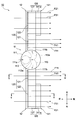
第1実施形態に係る送風装置が設けられた車両を上方から見た模式図である。
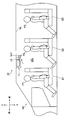
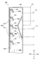
第1実施形態に係る送風装置を下方から見た模式図である。
図3のIV-IV断面を示す断面図である。
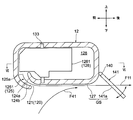
図3のV-V断面を示す断面図である。
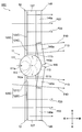
図4のVI-VI断面を示す断面図である。
第1実施形態の変形例に係る送風装置の断面図である。
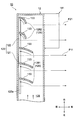
第2実施形態に係る送風装置を下方から見た模式図である。
図8のIX-IX断面を示す断面図である。
第3実施形態に係る送風装置を下方から見た模式図である。
第4実施形態に係る送風装置を下方から見た模式図である。
第5実施形態に係る送風装置を下方から見た模式図である。
以下、添付図面を参照しながら実施形態について説明する。説明の理解を容易にするため、各図面において同一の構成要素に対しては可能な限り同一の符号を付して、重複する説明は省略する。
まず、図1乃至図3を参照しながら、第1実施形態に係る送風装置10の概略について説明する。
送風装置10は、車両VHのキャビンVCの天井部VLに取り付けられている。送風装置10は、送風ユニット11と、2つのダクト12,12と、2つの外側フラップ141,141と、を備える。キャビンVCには、1列目~3列目のシートS1,S2,S3が設けられている。送風装置10は、このシートS1,S2,S3のそれぞれに着席する乗員P1,P2,P3の頭部よりも上方に配置されている。
尚、以下の説明において、前後方向、左右方向、上下方向について説明するときは、それぞれ乗員P1,P2,P3が車両VHの前進方向を向いた場合の前後方向、左右方向、上下方向を意味するものとする。
送風ユニット11は、空気流を発生させる装置であり、図3に示されるように、ケース111と、送風機112と、分岐体113と、を有している。
ケース111は、その外形が略円柱形状に形成されており、左右方向においてキャビンVCの中央部に配置されている。ケース111の前端部には、ケース111の内外を連通する吸込口111aが形成されている。また、ケース111の左右両側面には、ケース111の内外を連通する一対の吹出口111b,111bがそれぞれ形成されている。
送風機112は、空気流を発生させる電動送風機であり、ケース111に収容されている。送風機112は、その内部に遠心式多翼ファン(不図示)を有している。この遠心式多翼ファンが回転することにより、キャビンVCの空気がケース111の吸込口111aを介して吸い込まれ、送風機112の吹出口112aから後方側に吹き出される。
分岐体113は、前端部から後方側に延び、途中で左右に分岐して後端部まで延びるT字状の部材である。分岐体113は、ケース111に収容されており、ケース111の内部において分岐流路113aを区画形成している。分岐体113は、前端部が送風機112の吹出口112aに接続されており、後端部がケース111の一対の吹出口111b,111bに接続されている。これにより、送風機112の吹出口112aから吹き出された空気流は、分岐流路113aに導入されて左右に分流し、ケース111の吹出口111b,111bに供給される。
ダクト12,12は、それぞれ送風ユニット11の左右両側に設けられている。ダクト12,12は、左右方向において、送風ユニット11側からキャビンVCの端部側に向かって直線状に延びるように形成された中空の部材である。ダクト12,12の送風ユニット11側の端部は、ケース111の吹出口111bに接続されている。尚、ダクト12,12は、左右方向に略対称に形成されているため、以下、右側のダクト12を例にとって説明する。
ダクト12の下側面127であって、ダクト12の前端部寄りの部位には、左右方向を長手方向とするスリット状の吹出口120が形成されている。この吹出口120は、左右方向において、送風機112寄りの部位である第1吹出部121と、第1吹出部121よりも送風機112から遠い部位である第2吹出部122からなる。また、吹出口120は、第1吹出部121と第2吹出部122とが連なった単一の開口とされている。
外側フラップ141は、左右方向における寸法が吹出口120よりも小さい平板状の部材である。外側フラップ141は、ダクト12の外部であって、第2吹出部122の後方側に配置されている。また、外側フラップ141は、そのダクト12側の一端部が、左右方向に略水平に延びる回動軸140(図4参照)によって支持されている。これにより、外側フラップ141は回動軸140を中心として回動自在で、任意の位置で静止することが可能とされている。
続いて、図2乃至図6を参照しながら、第1実施形態に係る送風装置10のダクト12の詳細な構成について説明する。
図4及び図5に示されるように、吹出口120は、ダクト12の下側面127のうちダクト内流路128の下方の部位に形成されており、ダクト内流路128の内外を連通している。ダクト12の壁面は、この吹出口120の後方側の端部が、ダクト内流路128の内部に入り込むように湾曲形成されている。これにより、互いに間隔を空けて配置されるダクト12の壁面124aと壁面124bとの間に、吹出口120に連通する絞り流路125が形成されている。絞り流路125は、入口125aから吹出口120に向かって断面積が漸次小さくなっている。この絞り流路125のうち、第1吹出部121に連通する第1連通部1251(図4参照)の断面積は、第2吹出部122に連通する第2連通部1252(図5参照)の断面積よりも小さい。
図6に示されるように、ダクト内流路128には、5つのガイドベーン126が、互いに間隔を空けて左右方向に直線状に並ぶように設けられている。ガイドベーン126は、左右方向において、キャビンVCの中央部寄りに配置される3つの第1ガイドベーン1261と、キャビンVCの端部寄りに配置される2つの第2ガイドベーン1262と、からなる。
第1ガイドベーン1261及び第2ガイドベーン1262は、いずれもその後端部を送風ユニット11側に向けるとともに、その前端部を絞り流路125の入口125a側に向けるように湾曲し、平面視で円弧状の外側面を有する板状部材である。第1ガイドベーン1261は、その前後方向における寸法が、第2ガイドベーン1262よりも大きい。また、第1ガイドベーン1261及び第2ガイドベーン1262は、ダクト12の吹出口120よりも上流側において、その前端部が絞り流路125の入口125aと平面視で重合するように設けられている。
また、第1ガイドベーン1261及び第2ガイドベーン1262は、その上端部及び下端部に、上下方向に突出する円柱状の回動軸133が形成されている。各回動軸133は、その上下の端部がダクト内流路128の壁面によって支持されている。これにより、第1ガイドベーン1261及び第2ガイドベーン1262は、いずれも各回動軸133を中心として回動自在とされている。
送風機112が発生させた空気流は、ケース111の吹出口111bを介してダクト12の内部に導入される。ダクト12の内部のダクト内流路128を流れる空気流は、前方向及び右方向の流速成分を有している。しかしながら、ガイドベーン126が図6に示される状態にあるときは、空気流はガイドベーン126の外側面に沿って流れることにより、右方向の流速成分を失う。これにより、空気流は、その向きを前後方向に略平行な方向に変えて、絞り流路125の入口125aに導かれる。
入口125aに導かれた空気流は、絞り流路125を吹出口120に向かって流れることで、その流速が高められる。ダクト内流路128の空気流は、前後方向に略平行な向きに入口125aに流入することから、慣性により、前後方向に略平行な向きのまま絞り流路125を通過し、吹出口120から後方側に吹き出される。したがって、吹出口120から後方側に吹き出される空気流の向きは、前後方向に略平行なものとなる。吹出口120から吹き出された空気流は、第1吹出部121から吹き出される第1空気流F11と、第2吹出部122から吹き出される第2空気流F21と、になる。
吹出口120から後方側に吹き出された第1空気流F11及び第2空気流F21は、まず、コアンダ効果によってダクト12の下側面127に沿って流れる。すなわち、ダクト12の下側面127と、後述する外側フラップ141の下側面141aとは、いずれも空気流を沿わせて流すガイド面GSを構成している。
吹出口120から第1空気流F11及び第2空気流F21が吹き出されると、周囲の空気が引き込まれて二次空気流F41,F51が形成される。この結果、第1空気流F11及び第2空気流F21は、二次空気流F41,F51と合流し、その流量が増大しながらダクト12の下側面127に沿って後方側に流れる。
ここで、前述したように、第1吹出部121は、第2吹出部122よりもダクト内流路128の上流側となる送風機112側に設けられている。このため、第1吹出部121に供給される空気流は、第2吹出部122に供給される空気流と比較して、送風機112から供給される過程において圧力損失が生じ難い。したがって、第1吹出部121に供給される空気流は、第2吹出部122に供給される空気流よりも圧力が高くなる。
また、5つのガイドベーン126のうち、第1ガイドベーン1261は、前後方向における寸法が、第2ガイドベーン1262よりも大きい。これにより、第1ガイドベーン1261は、第2ガイドベーン1262よりも多くの空気流をその外側面に沿わせて流し、第1連通部1251に導く。このため、第1ガイドベーン1261は、第1吹出部121に供給される空気流の圧力を、第2吹出部122に供給される空気流の圧力よりも高めるように作用する。
さらに、絞り流路125のうち、第1吹出部121に連通する第1連通部1251の断面積は、第2吹出部122に連通する第2連通部1252の断面積よりも小さい。このため、第1連通部1251を通過して第1吹出部121に供給される空気流は、第2連通部1252を通過して第2吹出部122に供給される空気流よりもさらに圧力が高まる。
以上のようにして、吹出口120の第1吹出部121に供給される空気流の圧力が高められることにより、第1吹出部121から吹き出される第1空気流F11の流速は、第2吹出部122から吹き出される第2空気流F21の流速よりも大きくなる。
図2乃至図4に示されるように、吹出口120の第1吹出部121から後方側に吹き出された第1空気流F11は、コアンダ効果によりダクト12の下側面127に沿って流れた後、その下側面127に沿う方向で更にダクト12の後方側に流れる。第1空気流F11は、左右方向においてキャビンVCの中央部寄りの部分を流れて、乗員P3が居る位置(第1位置)に供給される。
一方、図2、図3及び図5に示されるように、吹出口120の第2吹出部122から後方側に吹き出された第2空気流F21は、コアンダ効果によりダクト12の下側面127に沿って流れた後、次に外側フラップ141の下側面141aに沿って流れる。第2空気流F21は、下方に延びるように傾斜する外側フラップ141によって、その向きを前方側に変更され、乗員P2が居る位置(第2位置)に供給される。
このように、第1実施形態に係る送風装置10は、吹き出される空気流の流速が吹出口120の部位によって異なる。つまり、送風機112に比較的近い部位である第1吹出部121から吹き出される第1空気流F11は、送風機112から比較的遠い部位である第2吹出部122から吹き出される第2空気流F21よりも流速が大きくなるように構成されている。
したがって、この第1実施形態に係る送風装置10によれば、流速が比較的小さい第2空気流F21を乗員P2が居る位置に向けるとともに、流速が比較的大きい第1空気流F11を乗員P3が居る位置に向けることで、乗員P3にも十分な流量の空気流を供給することができる。これにより、前後方向において異なる位置に居る乗員P2,P3に、十分な流量の空気流を同時に供給することが可能となる。
第1実施形態の変形例に係る送風装置10Aについて、図7を参照しながら説明する。
送風装置10Aは、そのダクト12Aの内部の構成が、前述した第1実施形態に係る送風装置10のダクト12と異なる。したがって、前述した第1実施形態と同一の構成については、同一の符号を付すとともに説明を適宜省略する。
ダクト12の内部のダクト内流路128Aには、5つの第2ガイドベーン1262が互いに間隔を空けて左右方向に直線状に並ぶように設けられている。この5つの第2ガイドベーン1262は、その外側面に沿って空気流を流し、吹出口120の第1吹出部121及び第2吹出部122に導くように作用する。
また、ダクト12Aは、そのダクト内流路128Aに壁体129を有している。この壁体129は、左右方向において、第1吹出部121と第2吹出部122の境を頂点とするように、前方側に突出するように形成されている。
ダクト12Aのダクト内流路128Aにこのような壁体129が設けられることにより、送風機112からダクト内流路128Aに導入された空気流は、壁体129に沿って流れる。これにより、ダクト内流路128Aの空気流の多くが、吹出口120の第1吹出部121に導かれる。すなわち、吹出口120の第1吹出部121に供給される空気流は、第2吹出部122に供給される空気流よりも圧力が高まる。
以上のようにして、吹出口120の第1吹出部121に供給される空気流の圧力が高められることにより、第1吹出部121から吹き出される第1空気流F11の流速は、第2吹出部122から吹き出される第2空気流F21の流速よりも大きなものとなる。
したがって、この第1実施形態の変形例に係る送風装置10Aも、流速が比較的小さい第2空気流F21を乗員P2が居る位置に向けるとともに、流速が比較的大きい第1空気流F11を乗員P3が居る位置に向けることで、乗員P3にも十分な流量の空気流を供給することができる。これにより、前後方向において異なる位置に居る乗員P2,P3に、十分な流量の空気流を同時に供給することが可能となる。
第2実施形態に係る送風装置10Bについて、図8及び図9を参照しながら説明する。この第2実施形態に係る送風装置10Bは、その吹出口120Bと、内側フラップ142、中間フラップ143及び外側フラップ144と、の点で前述した第1実施形態に係る送風装置10と構成が異なる。したがって、前述した送風装置10と同一の構成については、同一の符号を付すとともに説明を適宜省略する。
送風装置10Bのダクト12の下側面127であって、ダクト12の前端部寄りの部位には、左右方向を長手方向とするスリット状の吹出口120Bが形成されている。この吹出口120Bは、左右方向において、送風機112寄りの部位である第1吹出部121Bと、キャビンVCの端部寄りの部位である第3吹出部123Bと、第1吹出部121Bと第3吹出部123Bとの間の部位である第2吹出部122Bと、からなる。また、吹出口120Bは、第1吹出部121Bと、第2吹出部122Bと、第3吹出部123Bとが連なった単一の開口とされている。
内側フラップ142、中間フラップ143及び外側フラップ144は、いずれも左右方向における寸法が吹出口120Bよりも小さい平板状の部材である。また、内側フラップ142と外側フラップ144の左右方向における寸法の合計は、中間フラップ143の左右方向における寸法よりも大きく設定されている。
内側フラップ142、中間フラップ143及び外側フラップ144は、いずれもダクト12の外部に配置されており、そのダクト12側の一端部が、左右方向に略水平に延びる回動軸140によって支持されている。これにより、内側フラップ142、中間フラップ143及び外側フラップ144は、回動軸140を中心として回動自在で、任意の位置で静止することが可能とされている。
内側フラップ142(第1フラップ)は、第1吹出部121Bの後方に配置されている。また、中間フラップ143(第2フラップ)は、第2吹出部122Bの後方に配置されている。さらに、外側フラップ144(第3フラップ)は、第3吹出部123Bの後方に配置されている。
ダクト内流路128の空気流は、前後方向に略平行な向きに入口125aに流入することから、慣性により、前後方向に略平行な向きのまま絞り流路125を通過し、ダクト12の吹出口120Bから後方に吹き出される。したがって、吹出口120Bから後方に吹き出される空気流の向きは、前後方向に略平行なものとなる。吹出口120Bから吹き出された空気流は、第1吹出部121Bから吹き出される第1空気流F12と、第2吹出部122Bから吹き出される第2空気流F22と、第3吹出部123Bから吹き出される第3空気流F32と、になる。
吹出口120Bから第1空気流F12、第2空気流F22及び第3空気流F32が吹き出されると、周囲の空気が引き込まれて二次空気流F42,F52,F62が形成される。この結果、第1空気流F12、第2空気流F22及び第3空気流F32は、二次空気流F42,F52,F62と合流し、その流量が増大しながらダクト12の下側面127に沿って後方側に流れる。
吹出口120Bのうち、最も送風機112に近い第1吹出部121Bは、第2吹出部122Bや第3吹出部123Bに比べて、供給される空気流の圧力が高まるように構成されている。また、第3吹出部123Bよりも送風機112に近い第2吹出部122Bは、第3吹出部123Bよりも供給される空気流の圧力が高まるように構成されている。
したがって、第1吹出部121Bから吹き出される第1空気流F12は、第2吹出部122Bから吹き出される第2空気流F22や、第3吹出部123Bから吹き出される第3空気流F32よりも流速が大きくなる。さらに、第2空気流F22は、第3空気流F32よりも流速が大きくなる。
吹出口120Bの第1吹出部121Bから後方側に吹き出された第1空気流F12は、コアンダ効果によりダクト12の下側面127に沿って流れた後、次に内側フラップ142の下側面142aに沿って流れる。内側フラップ142が図9に示されるような状態にあるときは、第1空気流F12は、下側面142aに沿う方向で更に後方側に流れる。この結果、第1空気流F12は、左右方向においてキャビンVCの中央部寄りの部分を流れて、乗員P3が居る位置に供給される。
一方、吹出口120Bの第2吹出部122Bから後方側に吹き出された第2空気流F22は、コアンダ効果によりダクト12の下側面127に沿って流れた後、次に中間フラップ143の下側面143aに沿って流れる。第2空気流F22は、下方に延びるように傾斜する中間フラップ143によって向きを前方側に変更され、乗員P2が居る位置に供給される。
吹出口120Bの第3吹出部123Bから後方側に吹き出された第3空気流F32は、コアンダ効果によりダクト12の下側面127に沿って流れた後、次に外側フラップ144の下側面144aに沿って流れる。第3空気流F32は、やや下方に延びるように傾斜する外側フラップ144によって、その向きをやや前方側に変更される。この結果、第3空気流F32は、左右方向においてキャビンVCの端部に沿って流れ、乗員P3が居る位置に供給される。
第2実施形態に係る送風装置10Bによれば、左右方向においてキャビンVCの中央部寄りの部分を流れる第1空気流F12と、キャビンVCの端部に沿って流れる第3空気流F32と、を乗員P3に供給することができる。すなわち、第1空気流F12及び第3空気流F32により、乗員P3を左右から包み込むように十分な流量の空気流を供給することができる。
第3空気流F32はキャビンVCの端部に沿って流れるため、拡散することなく、比較的容易に乗員P3が居る位置まで供給することができる。したがって、第3空気流F32の流速が十分に大きい場合は、外側フラップ144を用いることなく供給することもできる。すなわち、ダクト12の下側面127に沿って流れた第3空気流F32を、その後、外側フラップ144の下側面144aに沿わせることなく、下側面127の後端部から乗員P3が居る位置まで直接流して供給してもよい。
吹出口120Bから吹き出された空気流を乗員P3に向ける内側フラップ142及び外側フラップ144の左右方向における寸法の合計は、空気流を乗員P2に向ける中間フラップ143の左右方向における寸法よりも大きく設定されている。これにより、後方側の乗員P3に優先的に空気流を供給し、前後方向において異なる位置に居る乗員P2,P3に、十分な流量の空気流を同時に供給することが可能となる。
また、キャビンVCの2列目のシートS2及び3列目のシートS3の一方にしか乗員が居ない場合に、回動自在な内側フラップ142、中間フラップ143及び外側フラップ144の位置を適宜変更し、すべての空気流が当該乗員に供給されるように設定することができる。すなわち、乗員が居ないシートに向けて空気流が供給される無駄を抑制することが可能となる。
第3実施形態に係る送風装置10Cについて、図10を参照しながら説明する。この第3実施形態に係る送風装置10Cは、その吹出口120Cと、内側フラップ145(第1フラップ)及び外側フラップ146(第2フラップ)と、の点で前述した第1実施形態に係る送風装置10と構成が異なる。したがって、前述した送風装置10と同一の構成については、同一の符号を付すとともに説明を適宜省略する。
送風装置10Cのダクト12の下側面127であって、ダクト12の前端部寄りの部位には、左右方向を長手方向とするスリット状の吹出口120Cが形成されている。この吹出口120Cは、左右方向において、送風機112寄りの部位である第1吹出部121Cと、第1吹出部121Cよりも送風機112から遠い部位である第2吹出部122Cからなる。また、吹出口120Cは、第1吹出部121Cと第2吹出部122Cとが連なった単一の開口とされている。
内側フラップ145及び外側フラップ146は、いずれも左右方向における寸法が吹出口120Bよりも小さい平板状の部材である。内側フラップ145は、第1吹出部121Cの後方側に配置されている。また、外側フラップ146は、第2吹出部122Cの後方側に配置されている。
内側フラップ145は、左右方向において、キャビンVCの中央部側から端部側に向けて延びるように設けられている。すなわち、内側フラップ145の後端部は、前後方向に傾斜するように設けられている。
吹出口120Cの第1吹出部121Cから第1空気流F13が吹き出され、第2吹出部122Cから第2空気流F23が吹き出されると、周囲の空気が引き込まれて二次空気流F43,F53が形成される。この結果、第1空気流F13及び第2空気流F23は、二次空気流F43,F53と合流し、その流量が増大しながらダクト12の下側面127に沿って後方側に流れる。
吹出口120Cのうち、送風機112に近い第1吹出部121Cは、第2吹出部122Cに比べて、供給される空気流の圧力が高まるように構成されている。したがって、第1吹出部121Cから吹き出される第1空気流F13は、第2吹出部122Cから吹き出される第2空気流F23よりも流速が大きくなる。
吹出口120Cの第1吹出部121Cから後方側に吹き出された第1空気流F13は、コアンダ効果によりダクト12の下側面127に沿って流れた後、次に内側フラップ145の下側面145aに沿って流れる。第1空気流F13は、内側フラップ145に沿って流れる際に、左右方向においてキャビンVCの端部側に向かって流れるように、その向きが変化する。この結果、第1空気流F13は、左右方向においてキャビンVCの中央部寄りの部分を流れて、乗員P3が居る位置に供給される。
一方、吹出口120Cの第2吹出部122Cから後方側に吹き出された第2空気流F23は、コアンダ効果によりダクト12の下側面127に沿って流れた後、次に外側フラップ146の下側面146aに沿って流れる。第2空気流F23は、下方に延びるように傾斜する外側フラップ146により向きを前方側に変更され、乗員P2が居る位置に供給される。
第3実施形態に係る送風装置10Cでは、第1吹出部121Cから吹き出された第1空気流F13を、左右方向においてキャビンVCの端部側に向けて流す。これにより、左右方向に広範囲に広がる空気流を乗員P3に同時に供給することが可能となる。
第4実施形態に係る送風装置10Dについて、図11を参照しながら説明する。この第4実施形態に係る送風装置10Dは、そのダクト12Dと、吹出口120Dと、内側フラップ147(第1フラップ)及び外側フラップ148(第2フラップ)と、の点で前述した第1実施形態に係る送風装置10と構成が異なる。したがって、前述した送風装置10と同一の構成については、同一の符号を付すとともに説明を適宜省略する。
ダクト12D,12Dは、それぞれ送風ユニット11の左右両側に設けられている。ダクト12D,12Dは、左右方向において、送風ユニット11側からキャビンVCの端部側かつ前方側に向かって直線状に延びるように形成された中空の部材である。ダクト12D,12Dの送風ユニット11側の端部は、ケース111の吹出口111bに接続されている。尚、ダクト12D,12Dは、左右方向に略対称に形成されているため、以下、右側のダクト12を例にとって説明する。
ダクト12Dの下側面127Dであって、ダクト12Dの前端部寄りの部位には、左右方向を長手方向とするスリット状の吹出口120Dが形成されている。この吹出口120Dは、左右方向において、送風機112寄りの部位である第1吹出部121Dと、第1吹出部121Dよりも送風機112から遠い部位である第2吹出部122Dからなる。また、吹出口120Dは、第1吹出部121Dと第2吹出部122Dとが連なった単一の開口とされている。
この吹出口120Dは、ダクト12Dが延びる方向に沿って延びるように形成されている。つまり、吹出口120Dは、左右方向において、キャビンVCの中央部寄りの部位である第1吹出部121Dが、キャビンVCの端部寄りの部位である第2吹出部122Dよりも後方側に形成されている。
内側フラップ147及び外側フラップ148は、いずれも左右方向における寸法が吹出口120Dよりも小さい平板状の部材である。内側フラップ147は、第1吹出部121Dの後方側に配置されている。また、外側フラップ148は、第2吹出部122Dの後方側に配置されている。
ここで、内側フラップ147及び外側フラップ148は、いずれも、左右方向において、キャビンVCの中央部側から端部側に向けて延びるように設けられている。すなわち、内側フラップ147及び外側フラップ148の後端部は、前後方向に傾斜するように設けられている。
吹出口120Dの第1吹出部121Dから第1空気流F14が吹き出され、第2吹出部122Dから第2空気流F24が吹き出されると、周囲の空気が引き込まれて二次空気流F44,F54が形成される。この結果、第1空気流F14及び第2空気流F24は、二次空気流F44,F54と合流し、その流量が増大しながらダクト12の下側面127に沿って後方側に流れる。
吹出口120Dのうち、送風機112に近い第1吹出部121Dは、第2吹出部122Dに比べて、供給される空気流の圧力が高まるように構成されている。したがって、第1吹出部121Dから吹き出される第1空気流F14は、第2吹出部122Dから吹き出される第2空気流F24よりも流速が大きくなる。
吹出口120Dの第1吹出部121Dから後方側に吹き出された第1空気流F14は、コアンダ効果によりダクト12Dの下側面127Dに沿って流れた後、次に内側フラップ147の下側面147aに沿って流れる。第1空気流F14は、内側フラップ147により、左右方向においてキャビンVCの端部側に向かって流れるように、その向きが変化する。この結果、第1空気流F14は、左右方向においてキャビンVCの中央部寄りを流れて、乗員P3が居る位置に供給される。
一方、吹出口120Dの第2吹出部122Dから後方側に吹き出された第2空気流F24は、コアンダ効果によりダクト12Dの下側面127Dに沿って流れた後、次に外側フラップ148の下側面148aに沿って流れる。下方に延びるように傾斜する外側フラップ148により、第2空気流F24の向きは前方側、且つ、左右方向においてキャビンVCの端部側に変化する。この結果、第2空気流F24は、乗員P2が居る位置に供給される。
第4実施形態に係る送風装置10Dは、第1吹出部121Dから吹き出された第1空気流F14と、第2吹出部122Dから吹き出された第2空気流F24と、を左右方向においてキャビンVCの端部側に向けて流す。これにより、送風装置10Dの左右方向における寸法を小さくしながらも、左右方向に広範囲に広がる空気流を乗員P2及びP3に同時に供給することが可能となる。
第5実施形態に係る送風装置10Eについて、図12を参照しながら説明する。この第5実施形態に係る送風装置10Eは、その送風ユニット11Eと、ダクト12Eと、吹出口120Eと、内側フラップ149(第1フラップ)及び外側フラップ150(第2フラップ)と、の点で前述した第1実施形態に係る送風装置10と構成が異なる。したがって、前述した送風装置10と同一の構成については、同一の符号を付すとともに説明を適宜省略する。
送風ユニット11Eは、空気流を発生させる装置であり、ケース111Eと、送風機112と、内部ダクト113Eと、を有している。
ケース111Eは、その外形が略円柱形状に形成されており、左右方向においてキャビンVCの中央部に配置されている。ケース111Eの前端部には、ケース111Eの内外を連通する吸込口111Eaが形成されている。また、ケース111Eの後面には、ケース111Eの内外を連通する単一の吹出口111Ebが形成されている。
送風機112は、空気流を発生させる電動送風機であり、ケース111Eに収容されている。送風機112は、その内部に遠心式多翼ファン(不図示)を有している。この遠心式多翼ファンが回転することにより、キャビンVCの空気がケース111Eの吸込口111Eaを介して吸い込まれ、送風機112の吹出口112aから後方側に向けて吹き出される。
内部ダクト113Eは、前端部から後方側に延び、拡大して後端部まで延びる部材である。内部ダクト113Eは、ケース111Eに収容されており、ケース111Eの内部において内部流路113Eaを区画形成している。内部ダクト113Eは、前端部が送風機112の吹出口112aに接続されており、後端部がケース111Eの吹出口111Ebに接続されている。これにより、送風機112の吹出口112aから吹き出された空気流は、内部ダクト113Eに導入され、ケース111Eの吹出口111Ebに供給される。
ダクト12Eは、送風ユニット11Eの後端部に設けられている。ダクト12Eは、左右方向において、送風ユニット11E側からキャビンVCの端部側に向けて直線状に延びるように形成された中空の部材である。ダクト12Eの送風ユニット11E側の端部は、ケース111Eの吹出口111Ebに接続されている。
ダクト12Eの下側面127Eであって前端部寄りの部位と、ケース111Eの下側面には、その両者に跨るように、左右方向を長手方向とするスリット状の吹出口120Eが形成されている。この吹出口120Eは、左右方向において、送風機112寄りの部位である第1吹出部121Eと、第1吹出部121Eよりも送風機112から遠い部位である第2吹出部122Eからなる。また、吹出口120Eは、第1吹出部121と第2吹出部122とが連なった単一の開口とされている。
吹出口120Eの第1吹出部121Eから第1空気流F15が吹き出され、第2吹出部122Eから第2空気流F25が吹き出されると、周囲の空気が引き込まれて二次空気流F45,F55が形成される。この結果、第1空気流F15及び第2空気流F25は、二次空気流F45,F55と合流し、その流量が増大しながらダクト12Eの下側面127Eに沿って後方側に流れる。
吹出口120Eのうち、送風機112に近い第1吹出部121Eは、第2吹出部122Eに比べて、供給される空気流の圧力が高まるように構成されている。したがって、第1吹出部121Eから吹き出される第1空気流F15は、第2吹出部122Eから吹き出される第2空気流F25よりも流速が大きくなる。
吹出口120Eの第1吹出部121Eから後方側に吹き出された第1空気流F15は、コアンダ効果によりケース111Eの下側面及びダクト12Eの下側面127Eに沿って流れた後、次に内側フラップ149の下側面149aに沿って流れる。第1空気流F15は、下側面149aに沿う方向で更に後方側に流れる。この結果、第1空気流F15は、左右方向においてキャビンVCの中央部寄りの部分を流れて、乗員P3が居る位置に供給される。
一方、吹出口120Eの第2吹出部122Eから後方側に吹き出された第2空気流F25は、コアンダ効果によりダクト12Eの下側面127Eに沿って流れた後、次に外側フラップ150の下側面150aに沿って流れる。第2空気流F25は、下方に延びるように傾斜する外側フラップ150によって向きを前方側に変更され、乗員P2が居る位置に供給される。
第5実施形態に係る送風装置10Eは、送風ユニット11Eのケース111Eによって吹出口120Eを形成することにより、左右方向における寸法を小さくしながらも、空気流を乗員P2及びP3に同時に供給することが可能となる。
以上、具体例を参照しつつ実施形態について説明した。しかし、本開示はこれらの具体例に限定されるものではない。すなわち、これら具体例に、当業者が適宜設計変更を加えたものも、本開示の範囲に包含される。例えば、前述した各具体例が備える各要素およびその配置、材料、条件、形状、サイズなどは、例示したものに限定されるわけではなく適宜変更することができる。また、前述した各実施形態が備える各要素は、技術的に可能な限りにおいて組み合わせることができ、これらを組み合わせたものも本開示の範囲に包含される。
Claims (14)
- 車両(VH)のキャビン(VC)に空気流を供給する送風装置(10,10A,10B,10C,10D,10E)であって、
空気流を発生させる送風機(112)と、
車両左右方向に延び、前記送風機が発生させた空気流が内部に導入されるとともに、その外側面の少なくとも一部が空気流を沿わせて流すガイド面(GS)を構成するダクト(12,12A,12D,12E)と、
前記ダクトに形成され、車両左右方向を長手方向とするスリット状を呈し、前記ダクトの内部の空気流を前記ガイド面に沿わせて車両後方側に吹き出す吹出口(120,120B,120C,120D,120E)と、を備え、
前記吹出口は、前記送風機寄りの部位である第1吹出部(121,121B,121C,121D,121E)と、前記第1吹出部よりも前記送風機から遠い部位である第2吹出部(122,122B,122C,122D,122E)と、を有し、
前記第2吹出部は、前記キャビンの第2位置に供給される第2空気流(F21,F22,F23,F24,F25)を吹き出し、
前記第1吹出部は、前記第2空気流よりも流速が大きく前記第2位置よりも車両後方側の第1位置に供給される第1空気流(F11,F12,F13,F14,F15)を吹き出す送風装置。 - 前記送風機は、車両左右方向において前記キャビンの中央部寄りに配置され、
前記ダクトは、車両左右方向において前記送風機側から前記キャビンの端部側に向かって延びる請求項1に記載の送風装置。 - 前記ダクトよりも車両後方側に設けられ、その外側面の少なくとも一部が前記ガイド面を構成するとともに、前記吹出口から吹き出された空気流の車両前後方向の流速成分を変更するフラップ(141,142,143,144,145,146,147,148,149,150)を備え、
前記フラップは、車両左右方向における寸法が、前記吹出口よりも小さい請求項2に記載の送風装置。 - 前記フラップ(141,143,146,148,150)は、前記第2空気流の車両前後方向の流速成分を変更する請求項3に記載の送風装置。
- 前記ダクト(12,12D,12E)よりも車両後方側に設けられ、その外側面の少なくとも一部が前記ガイド面を構成する第1フラップ(142,145,147,149)及び第2フラップ(143,146,148,150)を備え、
前記第1フラップは前記第1空気流(F12,F13,F14,F15)の車両前後方向の流速成分を変更し、前記第2フラップは前記第2空気流(F22,F23,F24,F25)の車両前後方向の流速成分を変更する請求項2に記載の送風装置。 - 前記第1フラップは、前記第2フラップよりも車両左右方向における寸法が大きい請求項5に記載の送風装置。
- 前記ダクトは、前記第1吹出部に供給される空気流の圧力が、前記第2吹出部に供給される空気流の圧力よりも高くなるように構成されている請求項2に記載の送風装置。
- 前記ダクトは、前記第1吹出部に空気を導く第1ガイドベーン(1261)と、前記第2吹出部に空気を導く第2ガイドベーン(1262)と、を内部に有し、
前記第1ガイドベーンは、前記第2ガイドベーンよりも大きい請求項7に記載の送風装置。 - 前記ダクトは、前記吹出口に連通し前記吹出口に向かって断面積が漸次減少する絞り流路(125)を内部に有し、
前記絞り流路のうち、前記第1吹出部に連通する部位(1251)は、前記第2吹出部に連通する部位(1252)よりも断面積が小さい請求項7に記載の送風装置。 - 前記吹出口(120D)は、車両左右方向において、前記キャビンの中央部寄りの部位(121D)が、前記キャビンの端部寄りの部位(122D)よりも車両後方側に形成されている請求項2に記載の送風装置。
- 車両左右方向において、前記吹出口(120B)の前記キャビンの端部寄りの部位である第3吹出部(123B)は、前記第1位置に供給される第3空気流(F32)を吹き出す請求項2に記載の送風装置。
- 前記ダクト(12)よりも車両後方側に設けられ、その外側面の少なくとも一部が前記ガイド面を構成する第3フラップ(144)を備え、
前記第3フラップは、前記第3空気流の車両前後方向の流速成分を変更して前記第1位置に供給する請求項11に記載の送風装置。 - 前記ガイド面を構成する前記ダクトの外側面(127)は、前記第3空気流を当該外側面の車両後方側端部から前記第1位置まで直接流す請求項11に記載の送風装置。
- 前記送風機は、前記キャビンの内部に配置され、
前記ダクトは、前記送風機から所定方向と前記所定方向とは反対側の反対方向に延びる請求項1に記載の送風装置。
Priority Applications (1)
| Application Number | Priority Date | Filing Date | Title |
|---|---|---|---|
| CN201580055685.2A CN106794745B (zh) | 2014-10-17 | 2015-10-08 | 送风装置 |
Applications Claiming Priority (2)
| Application Number | Priority Date | Filing Date | Title |
|---|---|---|---|
| JP2014-212159 | 2014-10-17 | ||
| JP2014212159A JP6331955B2 (ja) | 2014-10-17 | 2014-10-17 | 送風装置 |
Publications (1)
| Publication Number | Publication Date |
|---|---|
| WO2016059778A1 true WO2016059778A1 (ja) | 2016-04-21 |
Family
ID=55746340
Family Applications (1)
| Application Number | Title | Priority Date | Filing Date |
|---|---|---|---|
| PCT/JP2015/005108 Ceased WO2016059778A1 (ja) | 2014-10-17 | 2015-10-08 | 送風装置 |
Country Status (3)
| Country | Link |
|---|---|
| JP (1) | JP6331955B2 (ja) |
| CN (1) | CN106794745B (ja) |
| WO (1) | WO2016059778A1 (ja) |
Cited By (2)
| Publication number | Priority date | Publication date | Assignee | Title |
|---|---|---|---|---|
| WO2017208611A1 (ja) * | 2016-05-30 | 2017-12-07 | 株式会社デンソー | 車載用サーキュレータ |
| WO2020066383A1 (ja) * | 2018-09-27 | 2020-04-02 | 株式会社デンソー | 車両用空調装置 |
Families Citing this family (3)
| Publication number | Priority date | Publication date | Assignee | Title |
|---|---|---|---|---|
| JP2017213921A (ja) * | 2016-05-30 | 2017-12-07 | 株式会社デンソー | 車載用サーキュレータ |
| CN109882976B (zh) * | 2019-03-15 | 2024-07-05 | 华南理工大学 | 一种整合供冷、通风、照明的天花板系统 |
| CN113619357B (zh) * | 2021-08-06 | 2026-04-10 | 蔚来汽车科技(安徽)有限公司 | 出风结构、立柱及车辆 |
Citations (3)
| Publication number | Priority date | Publication date | Assignee | Title |
|---|---|---|---|---|
| WO2013145172A1 (ja) * | 2012-03-28 | 2013-10-03 | トヨタ自動車株式会社 | 車両用空調装置 |
| JP2014004947A (ja) * | 2012-06-26 | 2014-01-16 | Denso Corp | 送風装置 |
| JP2014139066A (ja) * | 2012-12-20 | 2014-07-31 | Denso Corp | 車両用送風装置 |
Family Cites Families (4)
| Publication number | Priority date | Publication date | Assignee | Title |
|---|---|---|---|---|
| JP3622425B2 (ja) * | 1997-06-10 | 2005-02-23 | 株式会社デンソー | バス車両用空調装置 |
| DE10354032A1 (de) * | 2002-11-20 | 2004-06-03 | Denso Corp., Kariya | Fahrzeug-Klimaanlage |
| JP2005212746A (ja) * | 2004-02-02 | 2005-08-11 | Denso Corp | 吹出方向可変装置および車両用空調装置 |
| JP2009040304A (ja) * | 2007-08-10 | 2009-02-26 | Denso Corp | 車両用空調装置 |
-
2014
- 2014-10-17 JP JP2014212159A patent/JP6331955B2/ja not_active Expired - Fee Related
-
2015
- 2015-10-08 WO PCT/JP2015/005108 patent/WO2016059778A1/ja not_active Ceased
- 2015-10-08 CN CN201580055685.2A patent/CN106794745B/zh not_active Expired - Fee Related
Patent Citations (3)
| Publication number | Priority date | Publication date | Assignee | Title |
|---|---|---|---|---|
| WO2013145172A1 (ja) * | 2012-03-28 | 2013-10-03 | トヨタ自動車株式会社 | 車両用空調装置 |
| JP2014004947A (ja) * | 2012-06-26 | 2014-01-16 | Denso Corp | 送風装置 |
| JP2014139066A (ja) * | 2012-12-20 | 2014-07-31 | Denso Corp | 車両用送風装置 |
Cited By (4)
| Publication number | Priority date | Publication date | Assignee | Title |
|---|---|---|---|---|
| WO2017208611A1 (ja) * | 2016-05-30 | 2017-12-07 | 株式会社デンソー | 車載用サーキュレータ |
| JP2017213920A (ja) * | 2016-05-30 | 2017-12-07 | 株式会社デンソー | 車載用サーキュレータ |
| WO2020066383A1 (ja) * | 2018-09-27 | 2020-04-02 | 株式会社デンソー | 車両用空調装置 |
| JP2020050150A (ja) * | 2018-09-27 | 2020-04-02 | 株式会社デンソー | 車両用空調装置 |
Also Published As
| Publication number | Publication date |
|---|---|
| JP2016078653A (ja) | 2016-05-16 |
| JP6331955B2 (ja) | 2018-05-30 |
| CN106794745A (zh) | 2017-05-31 |
| CN106794745B (zh) | 2019-06-18 |
Similar Documents
| Publication | Publication Date | Title |
|---|---|---|
| JP6331955B2 (ja) | 送風装置 | |
| US10500926B2 (en) | Ventilation duct for ventilating a passenger interior of a motor vehicle | |
| KR101413928B1 (ko) | 선체 마찰 저항 저감 장치 | |
| JP6428004B2 (ja) | 送風装置 | |
| JP5827099B2 (ja) | レジスタ | |
| JP2016117473A5 (ja) | ||
| US9895960B2 (en) | Front defroster nozzle apparatus | |
| JP6399286B2 (ja) | 車両の空調装置 | |
| JP6358028B2 (ja) | 車両空調装置 | |
| JP6544165B2 (ja) | 送風装置 | |
| JP6631291B2 (ja) | 胴体表面に空力デバイスを有する移動体 | |
| JP6593704B2 (ja) | 車両用電池パックの周辺構造 | |
| WO2017081965A1 (ja) | 空気吹出装置 | |
| JP7281908B2 (ja) | 航空機の空調ダクト構造、航空機、および航空機の製造方法 | |
| JP2016137889A (ja) | 送風装置 | |
| WO2016051754A1 (ja) | 送風装置 | |
| WO2016117348A1 (ja) | 送風装置 | |
| JP2016074414A (ja) | 送風装置 | |
| JP6368328B2 (ja) | レジスタおよび車両 | |
| JP4382549B2 (ja) | 車両用デフロスタ装置 | |
| JP6634808B2 (ja) | 車両用レジスタ | |
| JP2016137889A5 (ja) | ||
| WO2016051753A1 (ja) | 送風装置 | |
| WO2017208611A1 (ja) | 車載用サーキュレータ |
Legal Events
| Date | Code | Title | Description |
|---|---|---|---|
| 121 | Ep: the epo has been informed by wipo that ep was designated in this application |
Ref document number: 15851342 Country of ref document: EP Kind code of ref document: A1 |
|
| NENP | Non-entry into the national phase |
Ref country code: DE |
|
| 122 | Ep: pct application non-entry in european phase |
Ref document number: 15851342 Country of ref document: EP Kind code of ref document: A1 |