WO2016059763A1 - Tube en acier faiblement allié pour puits de pétrole - Google Patents
Tube en acier faiblement allié pour puits de pétrole Download PDFInfo
- Publication number
- WO2016059763A1 WO2016059763A1 PCT/JP2015/005027 JP2015005027W WO2016059763A1 WO 2016059763 A1 WO2016059763 A1 WO 2016059763A1 JP 2015005027 W JP2015005027 W JP 2015005027W WO 2016059763 A1 WO2016059763 A1 WO 2016059763A1
- Authority
- WO
- WIPO (PCT)
- Prior art keywords
- steel pipe
- tempering
- content
- temperature
- steel
- Prior art date
Links
Images
Classifications
-
- C—CHEMISTRY; METALLURGY
- C22—METALLURGY; FERROUS OR NON-FERROUS ALLOYS; TREATMENT OF ALLOYS OR NON-FERROUS METALS
- C22C—ALLOYS
- C22C38/00—Ferrous alloys, e.g. steel alloys
- C22C38/18—Ferrous alloys, e.g. steel alloys containing chromium
- C22C38/22—Ferrous alloys, e.g. steel alloys containing chromium with molybdenum or tungsten
-
- C—CHEMISTRY; METALLURGY
- C21—METALLURGY OF IRON
- C21D—MODIFYING THE PHYSICAL STRUCTURE OF FERROUS METALS; GENERAL DEVICES FOR HEAT TREATMENT OF FERROUS OR NON-FERROUS METALS OR ALLOYS; MAKING METAL MALLEABLE, e.g. BY DECARBURISATION OR TEMPERING
- C21D9/00—Heat treatment, e.g. annealing, hardening, quenching or tempering, adapted for particular articles; Furnaces therefor
- C21D9/08—Heat treatment, e.g. annealing, hardening, quenching or tempering, adapted for particular articles; Furnaces therefor for tubular bodies or pipes
-
- C—CHEMISTRY; METALLURGY
- C22—METALLURGY; FERROUS OR NON-FERROUS ALLOYS; TREATMENT OF ALLOYS OR NON-FERROUS METALS
- C22C—ALLOYS
- C22C38/00—Ferrous alloys, e.g. steel alloys
-
- C—CHEMISTRY; METALLURGY
- C22—METALLURGY; FERROUS OR NON-FERROUS ALLOYS; TREATMENT OF ALLOYS OR NON-FERROUS METALS
- C22C—ALLOYS
- C22C38/00—Ferrous alloys, e.g. steel alloys
- C22C38/001—Ferrous alloys, e.g. steel alloys containing N
-
- C—CHEMISTRY; METALLURGY
- C22—METALLURGY; FERROUS OR NON-FERROUS ALLOYS; TREATMENT OF ALLOYS OR NON-FERROUS METALS
- C22C—ALLOYS
- C22C38/00—Ferrous alloys, e.g. steel alloys
- C22C38/002—Ferrous alloys, e.g. steel alloys containing In, Mg, or other elements not provided for in one single group C22C38/001 - C22C38/60
-
- C—CHEMISTRY; METALLURGY
- C22—METALLURGY; FERROUS OR NON-FERROUS ALLOYS; TREATMENT OF ALLOYS OR NON-FERROUS METALS
- C22C—ALLOYS
- C22C38/00—Ferrous alloys, e.g. steel alloys
- C22C38/02—Ferrous alloys, e.g. steel alloys containing silicon
-
- C—CHEMISTRY; METALLURGY
- C22—METALLURGY; FERROUS OR NON-FERROUS ALLOYS; TREATMENT OF ALLOYS OR NON-FERROUS METALS
- C22C—ALLOYS
- C22C38/00—Ferrous alloys, e.g. steel alloys
- C22C38/04—Ferrous alloys, e.g. steel alloys containing manganese
-
- C—CHEMISTRY; METALLURGY
- C22—METALLURGY; FERROUS OR NON-FERROUS ALLOYS; TREATMENT OF ALLOYS OR NON-FERROUS METALS
- C22C—ALLOYS
- C22C38/00—Ferrous alloys, e.g. steel alloys
- C22C38/06—Ferrous alloys, e.g. steel alloys containing aluminium
-
- C—CHEMISTRY; METALLURGY
- C22—METALLURGY; FERROUS OR NON-FERROUS ALLOYS; TREATMENT OF ALLOYS OR NON-FERROUS METALS
- C22C—ALLOYS
- C22C38/00—Ferrous alloys, e.g. steel alloys
- C22C38/18—Ferrous alloys, e.g. steel alloys containing chromium
- C22C38/24—Ferrous alloys, e.g. steel alloys containing chromium with vanadium
-
- C—CHEMISTRY; METALLURGY
- C22—METALLURGY; FERROUS OR NON-FERROUS ALLOYS; TREATMENT OF ALLOYS OR NON-FERROUS METALS
- C22C—ALLOYS
- C22C38/00—Ferrous alloys, e.g. steel alloys
- C22C38/18—Ferrous alloys, e.g. steel alloys containing chromium
- C22C38/26—Ferrous alloys, e.g. steel alloys containing chromium with niobium or tantalum
-
- C—CHEMISTRY; METALLURGY
- C22—METALLURGY; FERROUS OR NON-FERROUS ALLOYS; TREATMENT OF ALLOYS OR NON-FERROUS METALS
- C22C—ALLOYS
- C22C38/00—Ferrous alloys, e.g. steel alloys
- C22C38/18—Ferrous alloys, e.g. steel alloys containing chromium
- C22C38/28—Ferrous alloys, e.g. steel alloys containing chromium with titanium or zirconium
-
- C—CHEMISTRY; METALLURGY
- C22—METALLURGY; FERROUS OR NON-FERROUS ALLOYS; TREATMENT OF ALLOYS OR NON-FERROUS METALS
- C22C—ALLOYS
- C22C38/00—Ferrous alloys, e.g. steel alloys
- C22C38/18—Ferrous alloys, e.g. steel alloys containing chromium
- C22C38/32—Ferrous alloys, e.g. steel alloys containing chromium with boron
-
- C—CHEMISTRY; METALLURGY
- C22—METALLURGY; FERROUS OR NON-FERROUS ALLOYS; TREATMENT OF ALLOYS OR NON-FERROUS METALS
- C22C—ALLOYS
- C22C38/00—Ferrous alloys, e.g. steel alloys
- C22C38/18—Ferrous alloys, e.g. steel alloys containing chromium
- C22C38/40—Ferrous alloys, e.g. steel alloys containing chromium with nickel
- C22C38/44—Ferrous alloys, e.g. steel alloys containing chromium with nickel with molybdenum or tungsten
-
- C—CHEMISTRY; METALLURGY
- C22—METALLURGY; FERROUS OR NON-FERROUS ALLOYS; TREATMENT OF ALLOYS OR NON-FERROUS METALS
- C22C—ALLOYS
- C22C38/00—Ferrous alloys, e.g. steel alloys
- C22C38/18—Ferrous alloys, e.g. steel alloys containing chromium
- C22C38/40—Ferrous alloys, e.g. steel alloys containing chromium with nickel
- C22C38/46—Ferrous alloys, e.g. steel alloys containing chromium with nickel with vanadium
-
- C—CHEMISTRY; METALLURGY
- C22—METALLURGY; FERROUS OR NON-FERROUS ALLOYS; TREATMENT OF ALLOYS OR NON-FERROUS METALS
- C22C—ALLOYS
- C22C38/00—Ferrous alloys, e.g. steel alloys
- C22C38/18—Ferrous alloys, e.g. steel alloys containing chromium
- C22C38/40—Ferrous alloys, e.g. steel alloys containing chromium with nickel
- C22C38/48—Ferrous alloys, e.g. steel alloys containing chromium with nickel with niobium or tantalum
-
- C—CHEMISTRY; METALLURGY
- C22—METALLURGY; FERROUS OR NON-FERROUS ALLOYS; TREATMENT OF ALLOYS OR NON-FERROUS METALS
- C22C—ALLOYS
- C22C38/00—Ferrous alloys, e.g. steel alloys
- C22C38/18—Ferrous alloys, e.g. steel alloys containing chromium
- C22C38/40—Ferrous alloys, e.g. steel alloys containing chromium with nickel
- C22C38/50—Ferrous alloys, e.g. steel alloys containing chromium with nickel with titanium or zirconium
-
- C—CHEMISTRY; METALLURGY
- C22—METALLURGY; FERROUS OR NON-FERROUS ALLOYS; TREATMENT OF ALLOYS OR NON-FERROUS METALS
- C22C—ALLOYS
- C22C38/00—Ferrous alloys, e.g. steel alloys
- C22C38/18—Ferrous alloys, e.g. steel alloys containing chromium
- C22C38/40—Ferrous alloys, e.g. steel alloys containing chromium with nickel
- C22C38/54—Ferrous alloys, e.g. steel alloys containing chromium with nickel with boron
Definitions
- the present invention relates to a steel pipe, and more particularly to a steel pipe for an oil well.
- oil wells and gas wells are simply referred to as “oil wells”.
- oil wells and gas wells are simply referred to as “oil wells”.
- steel pipes for oil wells of 80 ksi class yield stress is 80 to 95 ksi, that is, 551 to 654 MPa
- 95 ksi class yield stress is 95 to 110 ksi, that is, 654 to 758 MPa
- oil well steel pipes of 110 ksi class yield stress is 110 to 125 ksi, that is, 758 to 862 MPa
- SSC resistance sulfide Stress Cracking resistance
- SSC resistance that can be endured in a 1 atm H 2 S environment is usually evaluated by a test method specified by NACE. Sex is guaranteed.
- the 1 atm H 2 S environment is referred to as a standard condition.
- Patent Document 1 JP-A-62-253720
- Patent Document 2 JP-A-59-232220
- Patent Document 3 JP-A-6-322478
- JP-A-8-31551 Patent Document 4
- JP-A-2000-256783 Patent Document 5
- JP-A-2000-297344 Patent Document 6
- JP-A-2005-350754 Patent Document 6
- Patent Document 9 Japanese Translations of PCT publication No. 2012-519238
- Patent Document 9 Japanese Patent Application Laid-Open No. 2012-263030
- Patent Document 1 proposes a method for improving the SSC resistance of oil well steel by reducing impurities such as Mn and P.
- Patent Document 2 proposes a method of increasing the SSC resistance of steel by performing quenching twice to refine crystal grains.
- Patent Document 3 proposes a method of increasing the SSC resistance of 125 ksi-class steel materials by refining the steel structure by induction heat treatment.
- Patent Document 4 proposes a method of improving the SSC resistance of 110 ksi class to 140 ksi class steel pipes by increasing the hardenability of steel by using a direct quenching method and further increasing the tempering temperature.
- Patent Document 5 and Patent Document 6 propose a method for increasing the SSC resistance of 110 ksi-class to 140 ksi-class low alloy oil country tubular goods by controlling the form of carbides.
- Patent Document 7 proposes a method for improving the SSC resistance of oil well steel pipes of 125 ksi (862 MPa) class or higher by controlling the dislocation density and the hydrogen diffusion coefficient to desired values.
- Patent Document 8 discloses a method for increasing the SSC resistance of 125 ksi (862 MPa) grade steel by performing multiple quenching on low alloy steel containing 0.3 to 0.5% C. suggest.
- Patent Document 9 proposes a method of controlling the form and number of carbides by adopting a tempering process of two-stage heat treatment. More specifically, in Patent Document 9, the number density of large M3C or M2C is suppressed, and the SSC resistance of 125 ksi (862 MPa) grade steel is improved.
- Patent Documents 1 to 9 even when the techniques disclosed in Patent Documents 1 to 9 are applied, in the case of an oil well steel pipe having a yield strength of 115 ksi (793 MPa) or more, excellent SSC resistance may not be stably obtained.
- An object of the present invention is to provide a low alloy oil well steel pipe having a yield strength of 115 ksi class or higher (793 MPa or higher) and excellent SSC resistance.
- the steel pipe for a low alloy oil well according to the present invention is, in mass%, C: 0.25 to 0.35%, Si: 0.05 to 0.50%, Mn: 0.10 to 1.50%, Cr: 0 .40 to 1.50%, Mo: 0.40 to 2.00%, V: 0.05 to 0.25%, Nb: 0.010 to 0.040%, Ti: 0.002 to 0.050 %, Sol.
- the chemical composition is P: 0.020% or less, S: 0.010% or less, O: 0.006% or less, Ni: 0.10% or less, Cu: 0.10% or less.
- the number of cementite having an equivalent circle diameter of 200 nm or more is 100/100 ⁇ m 2 or more.
- the yield strength of the steel pipe for low alloy oil well is 793 MPa or more.
- the above chemical composition may contain Ca: 0.0005 to 0.005%.
- the steel pipe for low alloy oil well according to the present invention has a yield strength of 115 ksi class or more (793 MPa or more) and excellent SSC resistance.
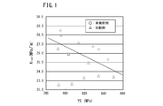
- FIG. 1 is a diagram showing the relationship between the yield strength YS and K 1SSC .
- the present inventors examined the SSC resistance of steel pipes for low alloy oil wells. As a result, the present inventors obtained the following knowledge.
- the steel pipe is tempered at a high temperature after containing Mo and V, which are alloy elements that increase the temper softening resistance. In this case, the dislocation density decreases. Therefore, the SSC resistance is increased.
- cementite When tempering is performed at a high temperature, cementite further grows to form coarse cementite. As described above, fine cementite is flat and its surface tends to induce SSC. However, coarse cementite spheroidizes and the specific surface area decreases. Therefore, coarse cementite is less likely to be a starting point for SSC generation than fine cementite. Therefore, if coarse cementite is produced instead of fine cementite, the SSC resistance is enhanced.
- cementite increases the strength of the steel pipe by precipitation strengthening.
- tempering is performed at a high temperature as described above, coarse cementite is produced, but the number of coarse cementite is small. In this case, although excellent SSC resistance is obtained, it is difficult to obtain a yield strength of 793 MPa or more.
- coarse cementite having an equivalent circle diameter of 200 nm or more is referred to as “coarse cementite”.
- low temperature tempering at 600 to 650 ° C. is performed in tempering, and then high temperature tempering at 670 to 720 ° C. is performed.
- many fine cementite is produced
- Fine cementite becomes the core of coarse cementite. If a large amount of fine cementite is precipitated by low temperature tempering, a large number of fine cementite grows and a large number of coarse cementite is formed in high temperature tempering. Therefore, the number density of coarse cementite increases. As a result, an oil well steel pipe having a high strength of 793 MPa or more and excellent SSC resistance can be obtained.
- the steel pipe for a low alloy oil well completed by the above knowledge is C: 0.25 to 0.35%, Si: 0.05 to 0.50%, Mn: 0.10 to 1.% by mass. 50%, Cr: 0.40 to 1.50%, Mo: 0.40 to 2.00%, V: 0.05 to 0.25%, Nb: 0.010 to 0.040%, Ti: 0 0.002 to 0.050%, sol.
- the chemical composition is P: 0.020% or less, S: 0.010% or less, O: 0.006% or less, Ni: 0.10% or less, Cu: 0.10% or less.
- the number of cementite having an equivalent circle diameter of 200 nm or more is 100/100 ⁇ m 2 or more.
- the yield strength of the steel pipe for low alloy oil well is 793 MPa or more.
- the chemical composition of the low alloy oil well steel pipe according to the present invention contains the following elements.
- the low alloy oil well steel pipe according to the present invention has a somewhat higher C content.
- C refines the martensite substructure to increase the strength of the steel.
- C further forms carbides and increases the strength of the steel.
- Examples of the carbide include cementite and alloy carbide (Mo carbide, V carbide, Nb carbide, Ti carbide, etc.). If the C content is high, the spheroidization of the carbide is further promoted, and a large number of coarse cementite is easily formed by the heat treatment described later, thereby making it possible to achieve both strength and SSC resistance. If the C content is less than 0.25%, these effects are insufficient.
- the C content is 0.25 to 0.35%.
- the minimum with preferable C content is 0.26%.
- the upper limit with preferable C content is 0.32%, More preferably, it is 0.30%.
- Si 0.05 to 0.50% Silicon (Si) deoxidizes steel. If the Si content is too low, this effect cannot be obtained. On the other hand, if the Si content is too high, the SSC resistance decreases. Therefore, the Si content is 0.05 to 0.50%.
- the minimum of preferable Si content is 0.10%, More preferably, it is 0.17%.
- the upper limit of the preferable Si content is 0.40%, and more preferably 0.35%.
- Mn 0.10 to 1.50%
- Manganese (Mn) deoxidizes steel. If the Mn content is too low, this effect cannot be obtained. On the other hand, if the Mn content is too high, it segregates at grain boundaries together with impurity elements such as phosphorus (P) and sulfur (S). In this case, the SSC resistance of the steel decreases. Therefore, the Mn content is 0.10 to 1.50%.
- the minimum of preferable Mn content is 0.20%, More preferably, it is 0.25%.
- the upper limit of the preferable Mn content is 1.00%, more preferably 0.75%.
- Chromium (Cr) increases the hardenability of the steel and increases the strength of the steel. If the Cr content is too low, the above effect cannot be obtained. On the other hand, if the Cr content is too high, the toughness and SSC resistance of the steel will decrease. Therefore, the Cr content is 0.40 to 1.50%.
- the minimum with preferable Cr content is 0.43%, More preferably, it is 0.48%.
- the upper limit with preferable Cr content is 1.20%, More preferably, it is 1.10%.
- Mo 0.40 to 2.00% Molybdenum (Mo) forms carbides and increases the temper softening resistance of the steel. As a result, Mo contributes to the improvement of SSC resistance by high temperature tempering. If the Mo content is too low, this effect cannot be obtained. On the other hand, if the Mo content is too high, the above effect is saturated. Therefore, the Mo content is 0.40 to 2.00%.
- the minimum with preferable Mo content is 0.50%, More preferably, it is 0.65%.
- the upper limit with preferable Mo content is 1.50%, More preferably, it is 0.90%.
- V 0.05-0.25% Vanadium (V), like Mo, forms carbides and increases the temper softening resistance of the steel. As a result, V contributes to the improvement of SSC resistance by high temperature tempering. If the V content is too low, the above effect cannot be obtained. On the other hand, if the V content is too high, the toughness of the steel decreases. Therefore, the V content is 0.05 to 0.25%.
- the minimum with preferable V content is 0.07%.
- the upper limit with preferable V content is 0.15%, More preferably, it is 0.12%.
- Niobium (Nb) combines with C or N to form a carbide, nitride or carbonitride. These precipitates (carbides, nitrides and carbonitrides) refine the steel substructure by the pinning effect and increase the SSC resistance of the steel. If the Nb content is too low, this effect cannot be obtained. On the other hand, if the Nb content is too high, precipitates are generated excessively, making the SSC resistance of the steel unstable. Therefore, the Nb content is 0.010 to 0.040%.
- the minimum with preferable Nb content is 0.012%, More preferably, it is 0.015%.
- the upper limit with preferable Nb content is 0.035%, More preferably, it is 0.030%.
- Titanium (Ti) is effective in preventing casting cracks. Ti forms nitrides and contributes to prevention of crystal grain coarsening. Therefore, in this embodiment, at least 0.002% Ti is contained. On the other hand, if the Ti content exceeds 0.050%, a large nitride is formed, which makes the SSC resistance of the steel unstable. Therefore, the Ti content is 0.002 to 0.050%.
- the lower limit of the preferable Ti content is 0.004%, and the upper limit of the preferable Ti content is 0.035%, more preferably 0.020%, still more preferably 0.015%.
- Al 0.005 to 0.10%
- Aluminum (Al) deoxidizes steel. If the Al content is too low, this effect cannot be obtained and the SSC resistance of the steel decreases. On the other hand, if the Al content is too high, inclusions increase and the SSC resistance of the steel decreases. Therefore, the Al content is 0.005 to 0.10%.
- the minimum with preferable Al content is 0.01%, More preferably, it is 0.02%.
- the upper limit with preferable Al content is 0.07%, More preferably, it is 0.06%.
- Al content means “acid-soluble Al”, that is, the content of “sol. Al”.
- N 0.007% or less Nitrogen (N) is inevitably contained. N combines with Ti to form fine TiN and refines the crystal grains. On the other hand, if the N content is too high, coarse nitrides are formed and the SSC resistance of the steel is lowered. Therefore, the N content is 0.007% or less.
- the preferable N content is 0.005% or less, more preferably 0.0045% or less. From the viewpoint of generating fine TiN to refine crystal grains, the preferable lower limit of the N content is 0.002%.
- B 0.0001 to 0.0035% Boron (B) increases the hardenability of the steel. If B is contained in an amount of 0.0001% (1 ppm) or more, the above effect can be obtained. On the other hand, B tends to form M 23 CB 6 at the grain boundary. When the B content exceeds 0.0035%, the SSC resistance of the steel decreases. Therefore, the B content is 0.0001 to 0.0035%.
- the minimum of preferable B content is 0.0003% (3 ppm), More preferably, it is 0.0005% (5 ppm).
- the B content is preferably 0.0030% or less, more preferably 0.0025% or less. In order to utilize the effect of B, it is preferable to suppress the N content or fix N with Ti so that B that does not bond to N can exist.
- Ca 0 to 0.005%
- Ca is an optional element and may not be contained. When contained, Ca combines with S in the steel to form sulfides and improves the shape of inclusions. In this case, the toughness of the steel increases. However, if the Ca content is too high, inclusions increase and the SSC resistance of the steel decreases. Therefore, the Ca content is 0 to 0.005%.
- the minimum with preferable Ca content is 0.0005%, More preferably, it is 0.001%.
- the upper limit with preferable Ca content is 0.003%, More preferably, it is 0.002%.
- the balance of the chemical composition of the low alloy oil well steel pipe of the present invention is composed of Fe and impurities.
- Impurities here refer to ores and scraps used as raw materials for steel, or elements mixed from the environment of the manufacturing process.
- the contents of P, S, O, Ni and Cu in the impurities are respectively defined as follows.
- Phosphorus (P) is an impurity. P segregates at the grain boundaries and lowers the SSC resistance of the steel. Therefore, the P content is 0.020% or less. P content is preferably 0.015% or less, more preferably 0.010% or less. The P content is preferably as low as possible.
- S 0.010% or less Sulfur (S) is an impurity. S segregates at the grain boundaries and lowers the SSC resistance of the steel. Therefore, the S content is 0.010% or less.
- a preferable S content is 0.005% or less, and more preferably 0.002% or less. The S content is preferably as low as possible.
- Oxygen (O) is an impurity. O forms a coarse oxide and reduces the corrosion resistance of the steel. Therefore, the O content is 0.006% or less.
- the O content is preferably 0.004% or less, more preferably 0.0015% or less.
- the O content is preferably as low as possible.
- Nickel (Ni) is an impurity. Ni decreases the SSC resistance of the steel. When the Ni content exceeds 0.10%, the SSC resistance is significantly reduced. Therefore, the content of Ni as an impurity element is 0.10% or less.
- the Ni content is preferably 0.05% or less, and more preferably 0.03% or less.
- Cu 0.10% or less Copper (Cu) is an impurity. Copper embrittles the steel and reduces the SSC resistance of the steel. Therefore, the Cu content is 0.10% or less.
- the Cu content is preferably 0.05% or less, and more preferably 0.03% or less.
- the structure of a low alloy oil well steel pipe having the above-described chemical composition is composed of tempered martensite and retained austenite having a volume fraction of 0 to less than 2%.
- the structure of the steel pipe for a low alloy oil well according to the present invention is substantially a tempered martensite structure. Therefore, the yield strength of the low alloy oil well steel pipe is high. Specifically, the yield strength of the steel pipe for a low alloy oil well of the present invention is 793 MPa or more (115 ksi class or more). The yield strength as used herein is defined by the 0.7% total elongation method.
- the volume ratio (%) of retained austenite is less than 2%.
- a lower volume fraction of retained austenite is preferred. Therefore, preferably, in the structure of the steel pipe for low alloy oil well, the volume ratio of retained austenite is 0% (that is, the structure made of tempered martensite). If the cooling stop temperature during quenching is sufficiently low, preferably 50 ° C. or less, the volume fraction of retained austenite can be suppressed to less than 2%.
- the volume fraction of retained austenite is determined by the following method using an X-ray diffraction method.
- a sample including the center of the thickness of the manufactured low alloy oil well steel pipe is collected.
- the surface of the collected sample is chemically polished.
- X-ray diffraction is performed on the chemically polished surface with CoK ⁇ rays as the incident X.
- the strength of the area of the ferrite phase ( ⁇ phase) (200) plane and (211) plane, the retained austenite phase ( ⁇ phase) (200) plane, (220) plane and (311) The strength for each area of the surface is obtained.
- V ⁇ 100 / (1+ (I ⁇ ⁇ R ⁇ ) / (I ⁇ ⁇ R ⁇ )) (1)
- I ⁇ and I ⁇ are the integrated intensities of the ⁇ phase and the ⁇ phase, respectively.
- R ⁇ and R ⁇ are scale factors of the ⁇ phase and the ⁇ phase, respectively, and are theoretically calculated crystallographically depending on the type of material and the plane orientation.
- the crystal grain size number based on ASTM E112 of the prior austenite grains (hereinafter also referred to as prior ⁇ grains) in the above structure is 9.0 or more. If the grain size number is 9.0 or more, excellent SSC resistance can be obtained even if the yield strength is 793 MPa or more.
- the preferred crystal grain number of the former ⁇ grain (hereinafter referred to as the former ⁇ grain number) is 9.5 or more.
- the old ⁇ grain size number may be measured using a steel material before quenching and before tempering (so-called as-quenched material), or may be measured using a tempered steel material (referred to as tempered material). Tempering does not change the size of the old ⁇ grains. Therefore, the size of the old ⁇ grains is the same whether the as-quenched material or the tempered material is used. If it is steel which has the said chemical composition, the old gamma particle size number will be set to 9.0 or more by the well-known hardening mentioned later.
- the number of cementite CN having an equivalent circle diameter of 200 nm or more in the above structure is 100/100 ⁇ m 2 or more.
- cementite increases the yield strength of steel pipes. Therefore, if the number of cementite is too small, the yield strength of the steel pipe is lowered. On the other hand, if the cementite is fine, the cementite has an acicular shape. In this case, cementite tends to be the starting point of SSC, and the SSC resistance is lowered.
- the number of fine cementite decreases when fine cementite is grown and coarsened. As a result, the SSC resistance is improved.
- the number of fine cementite is difficult to measure directly. Then, it substitutes by measuring the number of coarse cementite.
- the total amount of cementite is determined by the carbon content of the steel. Therefore, when the number of coarse cementite is large, the number of fine cementite is small.
- the number of coarse cementite CN is 100/100 ⁇ m 2 or more, excellent SSC resistance can be obtained even if the yield strength is 793 MPa or more.
- the coarse cementite number CN is measured by the following method.
- ⁇ ⁇ ⁇ ⁇ Collect a sample including the thickness center of the steel pipe.
- a surface hereinafter referred to as an observation surface
- the observation surface after polishing is etched using a night proofing solution.
- each visual field is 10 ⁇ m ⁇ 10 ⁇ m.
- the area of each cementite can be determined by, for example, image processing software (trade name: Image J1.47v).
- image processing software trade name: Image J1.47v.
- the diameter of a circle having the same area as the obtained area is defined as the equivalent circle diameter of the cementite.
- a cementite having an equivalent circle diameter of 200 nm or more that is, coarse cementite
- the total number TN of coarse cementite in all 10 fields is obtained.
- the lower limit of the preferable number of coarse cementite CN is 120/100 ⁇ m 2 .
- the upper limit of the coarse cementite number CN is not particularly limited, but in the case of the above-described chemical composition, the preferred upper limit of the coarse cementite number CN is 250/100 ⁇ m 2 .
- the method for producing a seamless steel pipe includes a pipe making process, a quenching process, and a tempering process.
- the steel having the above chemical composition is melted and refined by a well-known method. Subsequently, the molten steel is made into a continuous cast material by a continuous casting method.
- the continuous cast material is, for example, a slab, bloom or billet. Moreover, you may make molten steel into an ingot by an ingot-making method.
- the billet may be formed by hot rolling or may be formed by hot forging.
- the billet is hot-worked to produce a blank tube.
- the billet is heated in a heating furnace.
- the billet extracted from the heating furnace is hot-worked to produce a raw pipe (seamless steel pipe).
- the Mannesmann method is performed as hot working to manufacture a raw tube.
- the round billet is pierced and rolled by a piercing machine.
- the round billet that has been pierced and rolled is further hot-rolled by a mandrel mill, a reducer, a sizing mill, or the like into a blank tube.
- the blank tube may be manufactured from the billet by another hot working method.
- Quenching and tempering are performed on the hot-worked tube.
- the quenching temperature in the quenching treatment is Ac 3 point or higher.
- the upper limit of the preferable quenching temperature is 930 ° C.
- the old ⁇ grain size number of the steel pipe is set to 9.0 or more.
- BCC body-centered cubic
- FCC face-centered cubic
- off-line quenching In direct quenching or in-line quenching (soaking after quenching at 3 or more points of Ar without greatly lowering the temperature after hot pipe making), it is difficult to realize fine grains having an old ⁇ grain size number of 9.0 or more.
- a heat treatment (two-phase heat treatment as an intermediate heat treatment) may be performed at a two-phase temperature range from more than Ac 1 point to less than Ac 3 point. Also in this case, there is a remarkable effect in making the old ⁇ grains fine.
- the raw tube that has been quenched once by direct quenching or in-line quenching can be further refined off-line to further refine the old ⁇ grains.
- the steel pipe that has been directly hardened or in-line hardened is subjected to heat treatment at 500 ° C to 580 ° C for about 10 to 30 minutes. And impact cracking can be suppressed.
- Quenching is performed by quenching from a temperature of Ac 3 point or higher to a temperature of martensitic transformation start temperature or lower.
- the rapid cooling is, for example, water cooling or mist spray cooling.
- the old ⁇ grain size number of the blank after the above quenching process is 9.0 or more.
- the crystal grain size of the old ⁇ grains does not change even after tempering described later.
- the tempering step includes a low temperature tempering step and a high temperature tempering step.
- a low temperature tempering step is performed.
- the tempering temperature T L in the low temperature tempering step is 600 to 650 ° C.
- the Larson-Miller parameter LMP L in the low temperature tempering process is 17500 to 18750.
- the Larson-Miller parameter is defined by the following equation (3).
- LMP (T + 273) ⁇ (20 + log (t)) (3)
- T in the formula (3) is a tempering temperature (° C.), and t is a time (hr).
- the Larson-Miller parameter considering the heating process is Tsuneyama Akihiro, “Heat Treatment”, Vol. 42, No. 3, p163-166 (2002), “Interpretation of Physical Meaning of Tempering Parameters and Application to Continuous Heating / Cooling Heat Treatment Process”) It can be obtained by calculating as a parameter.
- the time from the start of heating to the end of heating is divided by a total number N of minute times ⁇ t.
- N the average temperature in the (n ⁇ 1) th section
- T n the average temperature in the nth section
- the time t 2 is the time required for obtaining the LMP equivalent to the integrated value of LMP calculated based on the heating in the section before the second section (that is, the first section) at the temperature T 2 (equivalent Time).
- LMP (n) (T n +273) ⁇ (20 + log (t n + ⁇ t)) (4)
- LMP (n) is an integrated value of LMP at the time when the heating of the nth section is completed.
- the time t n is an equivalent time for obtaining the LMP equivalent to the integrated value of the LMP at the time when the heating in the (n ⁇ 1) -th section is completed at the temperature T n .
- the time t n can be obtained from equation (5).
- Equation (4) is applied instead of Equation (3).
- the low temperature tempering step as described above, a large amount of C (carbon) that has been supersaturated in martensite is precipitated as cementite.
- the cementite deposited here is fine and becomes the core of coarse cementite.
- the low temperature tempering temperature T L is too low or the LMP L is too low, the amount of cementite deposited is small.
- the low temperature tempering temperature T L is too high or the LMP L is too high, coarse cementite grows, but the number of cementite precipitated is small.
- High temperature tempering process After the low temperature tempering step, a high temperature tempering step is performed. In the high temperature tempering process, fine cementite precipitated in the low temperature tempering process is coarsened to generate coarse cementite. Therefore, the strength of steel can be increased by coarse cementite while suppressing cementite from becoming the base point of SSC.
- the dislocation density in the steel is further reduced. Hydrogen entering the steel is trapped in the dislocations and becomes the starting point of SSC. For this reason, the higher the dislocation density, the lower the SSC resistance. By performing the high temperature tempering step, the dislocation density in the steel is reduced. Therefore, the SSC resistance is increased.
- the tempering temperature T H in the high-temperature tempering step for obtaining the above-described effect is 670 to 720 ° C.
- the Larson-Miller parameter LMP H defined by the equations (3) and (4) is 1.85 ⁇ 10 6. 4 to 2.05 ⁇ 10 4 .
- the cementite When the tempering temperature T H is too low or the LMP H is too low, the cementite is not coarsened, and the coarse cementite number CN is less than 100/100 ⁇ m 2 . Furthermore, the dislocation density is not sufficiently reduced. Therefore, the SSC resistance is low.
- the yield strength of the steel pipe having the above chemical composition is less than 793 MPa.
- the tempering step in the present invention may be performed in two stages of the low temperature tempering step and the high temperature tempering step. Specifically, after performing the low temperature tempering step, the steel pipe is cooled to room temperature. Next, a normal temperature steel pipe is heated and a high temperature tempering process is implemented. After performing the low temperature tempering step, the high temperature tempering step may be performed by heating the steel pipe to the high temperature tempering temperature T H as it is without cooling.
- the low temperature tempering step and the high temperature tempering step may be continuously performed by increasing the residence time in the temperature range of 600 to 650 ° C. while increasing the residence time in the high temperature range while increasing the temperature at a low speed (low speed increase). Tempering by temperature). For example, when tempering a steel pipe after quenching, a temperature range between 500 ° C. and 700 ° C. is continuously heated to 710 ° C. at a temperature increase rate of 3 ° C./min or less at an average temperature of 710 ° C. for a predetermined time ( For example, 60 minutes). In this case, the integrated value of the Larson-Miller parameter LMP L in the low temperature tempering temperature T L region (ie, 600 to 650 ° C.
- the tempering method is not particularly limited as long as LMP L in the low temperature tempering temperature T L region satisfies the above conditions and LMP H in the high temperature tempering temperature T H region satisfies the above conditions.
- the low alloy seamless steel pipe according to the present invention is manufactured.
- the structure of the manufactured seamless steel pipe consists of tempered martensite and 0 to less than 2% retained austenite. Further, the old ⁇ grain size number is 9.0 or more. Furthermore, the above-mentioned tempering step makes the coarse cementite count CN in the structure 100/100 ⁇ m 2 or more.
- Slab was manufactured by continuous casting using the above molten steel.
- the slab was mass-rolled to produce a round billet having a diameter of 310 mm.
- a round billet was pierced and rolled by the Mannesmann mandrel method to produce a seamless steel pipe having a diameter of 244.48 mm and a wall thickness of 13.84 mm.
- the steel pipe was subjected to soaking (in-line quenching) at 920 ° C. without lowering the temperature of the steel pipe to 3 points or less.
- soaking in-line quenching
- steel C and D were used, it stood to cool after hot pipe making.
- Each of the seamless steel pipes was re-heated to 900 ° C., soaked for 15 minutes and then water-cooled. However, as shown in Table 2, for test numbers 4 to 6 and test numbers 11 to 13, quenching was performed by reheating to 920 ° C. before final quenching, soaking for 15 minutes and then water cooling. Test number 15 used steel D. Test number 15 was scheduled to be quenched twice, but because the cracking was derived by the first quenching operation, the subsequent steps were stopped and excluded from the evaluation.
- the tempering treatment shown in Table 2 was performed on the seamless steel pipe after quenching.
- T L in Table 2 shows the soaking time at the tempering temperature T L (min).
- T H in Table 2 shows the soaking time at the tempering temperature T H (min).
- the temperature increase rate in the heating process was 8 ° C./min, and the temperature of the seamless steel pipe was continuously increased.
- LMP L and LMP H were calculated using Equations (3) and (4) as described above.
- ⁇ t was set to 1/60 hours (1 minute).
- T 1 average temperature in the first section. The results are shown in Table 2.
- test numbers 1 and 4 the temperature was continuously increased at a temperature increase rate of 2 ° C./min until the temperature reached 700 ° C., and test numbers 2 and 5 had a temperature increase rate of 3 until the tempering temperature reached 680 ° C.
- the temperature was continuously raised at 0 ° C./min, and tempered by soaking at 700 ° C. for 60 minutes for Test Nos. 1 and 4, and at 680 ° C. for 155 minutes for Test Nos. 2 and 5. That is, in the test numbers 1, 2, 4, and 5, tempering by a low temperature increase was performed.
- Table 2 shows LMP L (calculated by the formula (4)) in the temperature range of 600 to 650 ° C. in the slow temperature tempering.
- test numbers 7 to 13 only one-stage tempering (high temperature tempering) was performed. In this case, the temperature was continuously increased at 8 ° C./min.
- Yield strength test A No. 12 test piece (width 25 mm, gauge distance 200 mm) defined in JIS Z2201 was collected from the center of the thickness of the seamless steel pipe of each test number. The central axis of the test piece was the thickness center position of the seamless steel pipe, and was parallel to the longitudinal direction of the seamless steel pipe. Using the collected test pieces, a tensile test based on JIS Z2241 was performed in air at normal temperature (24 ° C.), and yield stress (YS) was obtained. Yield stress was determined by the 0.7% total elongation method. The obtained yield stress (MPa) is shown in Table 3. In the inventive examples, the yield strength of any seamless steel pipe was 115 ksi (793 MPa) or more.
- DCB test A DCB test (Double Cantilever Beam) test was performed on the seamless steel pipe of each test number, and the SSC resistance was evaluated.
- DCB test pieces having a thickness of 10 mm, a width of 25 mm, and a length of 100 mm were collected from each seamless steel pipe.
- a DCB test was performed in accordance with NACE (National Association of Corrosion Engineers) TM0177-2005MethodD.
- NACE National Association of Corrosion Engineers
- 5% sodium chloride + 0.5% acetic acid aqueous solution at normal temperature (24 ° C.) saturated with 1 atm hydrogen sulfide gas was used.
- the DCB test piece was immersed in the test bath for 336 hours to perform the DCB test.
- the specimen was placed under tension using a wedge that imparted a displacement of 0.51 mm (+0.03 mm / ⁇ 0.05 mm) to the two arms of the DCB specimen and exposed to the test solution for 14 days.
- K 1SSC Pa ((2 ( ⁇ 3) + 2.38 ⁇ (h / a)) ⁇ (B / Bn) 1 / ( ⁇ 3) ) / (B ⁇ h 3/2 ) (6)
- Equation (6) is the height of each arm of the DCB test piece
- B is the thickness of the DCB test piece
- Bn is the web thickness of the DCB test piece.
- the average value of the stress intensity factors obtained with the three DCB specimens for each test number was defined as the stress intensity factor K 1SSC for that test number.
- test numbers 3 and 6 were appropriate.
- two-stage tempering low temperature tempering and high temperature tempering
- the conditions of each tempering were appropriate. Therefore, the old ⁇ grain size number of the seamless steel pipe was 9.0 or more, and the coarse cementite number CN was 100/100 ⁇ m 2 or more.
- K 1 SSC was larger than the comparative example having the same yield strength YS, and had excellent SSC resistance.
- test numbers 1 and 2 and test numbers 4 and 5 were appropriate. Furthermore, low-temperature temperature raising and tempering were performed, and the conditions were appropriate. Therefore, the old ⁇ grain size number of the seamless steel pipe was 9.0 or more, and the coarse cementite number CN was 100/100 ⁇ m 2 or more. Furthermore, K 1 SSC was larger than the comparative example having the same yield strength YS, and had excellent SSC resistance.
- Test No. 14 was subjected to two-stage tempering, but the C content was 0.20%, which was less than the lower limit of the present invention, so the coarse cementite number CN was less than 100/100 ⁇ m 2 .
- Test number 16 was also subjected to two-stage tempering, but because the high temperature tempering LMP H was too large, the yield strength was too low for YS.
- FIG. 1 illustrates the results of Table 3 as the relationship between the yield strength YS and K 1SSC .
- K 1 SSC tends to decrease with increasing YS.
- FIG. 1 it was found that the steel pipe of the present invention exhibits a higher K 1 SSC at the same yield strength.
Abstract
Priority Applications (10)
| Application Number | Priority Date | Filing Date | Title |
|---|---|---|---|
| US15/518,024 US10752979B2 (en) | 2014-10-17 | 2015-10-02 | Low alloy oil-well steel pipe |
| CN201580055912.1A CN107075636B (zh) | 2014-10-17 | 2015-10-02 | 低合金油井用钢管 |
| MX2017004757A MX2017004757A (es) | 2014-10-17 | 2015-10-02 | Tubo de acero para pozos petroleros de baja aleacion. |
| JP2016553962A JP6103156B2 (ja) | 2014-10-17 | 2015-10-02 | 低合金油井用鋼管 |
| RU2017116969A RU2664500C1 (ru) | 2014-10-17 | 2015-10-02 | Нефтепромысловая труба из низколегированной стали |
| AU2015331943A AU2015331943B2 (en) | 2014-10-17 | 2015-10-02 | Low alloy oil-well steel pipe |
| BR112017006937-7A BR112017006937B1 (pt) | 2014-10-17 | 2015-10-02 | tubo de aço de baixa liga para poço de óleo |
| ES15850786T ES2745820T3 (es) | 2014-10-17 | 2015-10-02 | Tubería de acero de baja aleación para pozos de petróleo |
| CA2963755A CA2963755C (fr) | 2014-10-17 | 2015-10-02 | Tube en acier faiblement allie pour puits de petrole |
| EP15850786.3A EP3208358B1 (fr) | 2014-10-17 | 2015-10-02 | Tube en acier faiblement allié pour puits de pétrole |
Applications Claiming Priority (2)
| Application Number | Priority Date | Filing Date | Title |
|---|---|---|---|
| JP2014-213094 | 2014-10-17 | ||
| JP2014213094 | 2014-10-17 |
Publications (1)
| Publication Number | Publication Date |
|---|---|
| WO2016059763A1 true WO2016059763A1 (fr) | 2016-04-21 |
Family
ID=55746325
Family Applications (1)
| Application Number | Title | Priority Date | Filing Date |
|---|---|---|---|
| PCT/JP2015/005027 WO2016059763A1 (fr) | 2014-10-17 | 2015-10-02 | Tube en acier faiblement allié pour puits de pétrole |
Country Status (12)
| Country | Link |
|---|---|
| US (1) | US10752979B2 (fr) |
| EP (1) | EP3208358B1 (fr) |
| JP (1) | JP6103156B2 (fr) |
| CN (1) | CN107075636B (fr) |
| AR (1) | AR103128A1 (fr) |
| AU (1) | AU2015331943B2 (fr) |
| BR (1) | BR112017006937B1 (fr) |
| CA (1) | CA2963755C (fr) |
| ES (1) | ES2745820T3 (fr) |
| MX (1) | MX2017004757A (fr) |
| RU (1) | RU2664500C1 (fr) |
| WO (1) | WO2016059763A1 (fr) |
Cited By (7)
| Publication number | Priority date | Publication date | Assignee | Title |
|---|---|---|---|---|
| WO2017200033A1 (fr) * | 2016-05-20 | 2017-11-23 | 新日鐵住金株式会社 | Tube d'acier sans soudure et son procédé de production |
| WO2018066689A1 (fr) * | 2016-10-06 | 2018-04-12 | 新日鐵住金株式会社 | Matériau en acier, tuyau en acier pour des puits de pétrole et procédé permettant de produire un matériau en acier |
| WO2019167945A1 (fr) * | 2018-02-28 | 2019-09-06 | 日本製鉄株式会社 | Matériau en acier approprié pour être utilisé dans un environnement acide |
| WO2020071217A1 (fr) * | 2018-10-04 | 2020-04-09 | 日本製鉄株式会社 | Matériau en acier approprié pour être utilisé dans un environnement acide |
| JPWO2021039431A1 (fr) * | 2019-08-27 | 2021-03-04 | ||
| JPWO2020196019A1 (ja) * | 2019-03-22 | 2021-12-09 | 日本製鉄株式会社 | サワー環境での使用に適した継目無鋼管 |
| RU2785314C2 (ru) * | 2018-02-23 | 2022-12-06 | Валлурек Дойчланд Гмбх | Стали с высокой прочностью при растяжении и высокой ударной вязкостью |
Families Citing this family (3)
| Publication number | Priority date | Publication date | Assignee | Title |
|---|---|---|---|---|
| AR101200A1 (es) * | 2014-07-25 | 2016-11-30 | Nippon Steel & Sumitomo Metal Corp | Tubo de acero de baja aleación para pozo de petróleo |
| WO2017182280A1 (fr) * | 2016-04-21 | 2017-10-26 | Novo Nordisk A/S | Procédé de production de canule d'aiguille à partie d'extrémité réduite, par gravure électrochimique |
| CN116024491A (zh) * | 2021-10-27 | 2023-04-28 | 宝山钢铁股份有限公司 | 一种低硬度高韧性锯片钢及其制造方法 |
Citations (4)
| Publication number | Priority date | Publication date | Assignee | Title |
|---|---|---|---|---|
| JPS634047A (ja) * | 1986-06-20 | 1988-01-09 | Sumitomo Metal Ind Ltd | 耐硫化物割れ性に優れた高張力油井用鋼 |
| JPS63230851A (ja) * | 1987-03-20 | 1988-09-27 | Sumitomo Metal Ind Ltd | 耐食性に優れた油井管用低合金鋼 |
| JPH09249935A (ja) * | 1996-03-13 | 1997-09-22 | Sumitomo Metal Ind Ltd | 耐硫化物応力割れ性に優れる高強度鋼材とその製造方法 |
| JP2006265657A (ja) * | 2005-03-24 | 2006-10-05 | Sumitomo Metal Ind Ltd | 耐硫化物応力割れ性に優れた油井管用鋼および油井用継目無鋼管の製造方法 |
Family Cites Families (21)
| Publication number | Priority date | Publication date | Assignee | Title |
|---|---|---|---|---|
| JPS59232220A (ja) | 1983-06-14 | 1984-12-27 | Sumitomo Metal Ind Ltd | 耐硫化物腐食割れ性に優れた高強度鋼の製法 |
| JPH06104849B2 (ja) | 1986-04-25 | 1994-12-21 | 新日本製鐵株式会社 | 硫化物応力割れ抵抗性に優れた低合金高張力油井用鋼の製造方法 |
| JP3358135B2 (ja) | 1993-02-26 | 2002-12-16 | 新日本製鐵株式会社 | 耐硫化物応力割れ抵抗性に優れた高強度鋼およびその製造方法 |
| JP3755163B2 (ja) | 1995-05-15 | 2006-03-15 | 住友金属工業株式会社 | 耐硫化物応力割れ性に優れた高強度継目無鋼管の製造方法 |
| EP0828007B1 (fr) * | 1995-05-15 | 2001-11-14 | Sumitomo Metal Industries, Ltd. | Procede de production de tubes d'acier sans soudure a haute resistance, non susceptibles de fissuration par les composes soufres |
| JP2000256783A (ja) | 1999-03-11 | 2000-09-19 | Sumitomo Metal Ind Ltd | 靭性と耐硫化物応力腐食割れ性に優れる高強度油井用鋼およびその製造方法 |
| JP4058840B2 (ja) | 1999-04-09 | 2008-03-12 | 住友金属工業株式会社 | 靭性と耐硫化物応力腐食割れ性に優れる油井用鋼およびその製造方法 |
| JP3449311B2 (ja) | 1999-09-06 | 2003-09-22 | 住友金属工業株式会社 | 高靱性・高耐食性継目無鋼管 |
| RU2233906C1 (ru) * | 2003-04-03 | 2004-08-10 | Открытое акционерное общество "Машиностроительный завод" | Аустенитная сталь |
| WO2005090615A1 (fr) * | 2004-03-24 | 2005-09-29 | Sumitomo Metal Industries, Ltd. | Processus de production d'un acier faiblement allié excellant dans la résistance à la corrosion |
| JP4140556B2 (ja) | 2004-06-14 | 2008-08-27 | 住友金属工業株式会社 | 耐硫化物応力割れ性に優れた低合金油井管用鋼 |
| JP4135691B2 (ja) * | 2004-07-20 | 2008-08-20 | 住友金属工業株式会社 | 窒化物系介在物形態制御鋼 |
| FR2942808B1 (fr) * | 2009-03-03 | 2011-02-18 | Vallourec Mannesmann Oil & Gas | Acier faiblement allie a limite d'elasticite elevee et haute resistance a la fissuration sous contrainte par les sulfures. |
| AR075976A1 (es) * | 2009-03-30 | 2011-05-11 | Sumitomo Metal Ind | Metodo para la manufactura de tuberias sin costura |
| JP5728836B2 (ja) | 2009-06-24 | 2015-06-03 | Jfeスチール株式会社 | 耐硫化物応力割れ性に優れた油井用高強度継目無鋼管の製造方法 |
| JP5779984B2 (ja) | 2010-06-21 | 2015-09-16 | Jfeスチール株式会社 | 耐硫化物応力割れ性に優れた油井用鋼管及びその製造方法 |
| EP2476772A1 (fr) * | 2011-01-13 | 2012-07-18 | Rovalma, S.A. | Acier avec haute résistance à l'usure et haute diffusion thermique |
| AR088424A1 (es) | 2011-08-22 | 2014-06-11 | Nippon Steel & Sumitomo Metal Corp | Tubo de acero para pozo de petroleo con excelente resistencia a la corrosion bajo tension por presencia de sulfuros |
| JP2013129879A (ja) | 2011-12-22 | 2013-07-04 | Jfe Steel Corp | 耐硫化物応力割れ性に優れた油井用高強度継目無鋼管およびその製造方法 |
| EA025503B1 (ru) | 2012-03-07 | 2016-12-30 | Ниппон Стил Энд Сумитомо Метал Корпорейшн | Способ изготовления высокопрочных стальных изделий с улучшенной стойкостью к сульфидному растрескиванию под напряжением |
| AR100722A1 (es) | 2014-06-09 | 2016-10-26 | Nippon Steel & Sumitomo Metal Corp | Tubo de acero de baja aleación para un pozo de petróleo |
-
2015
- 2015-10-02 AU AU2015331943A patent/AU2015331943B2/en active Active
- 2015-10-02 ES ES15850786T patent/ES2745820T3/es active Active
- 2015-10-02 JP JP2016553962A patent/JP6103156B2/ja active Active
- 2015-10-02 CA CA2963755A patent/CA2963755C/fr not_active Expired - Fee Related
- 2015-10-02 MX MX2017004757A patent/MX2017004757A/es unknown
- 2015-10-02 CN CN201580055912.1A patent/CN107075636B/zh active Active
- 2015-10-02 WO PCT/JP2015/005027 patent/WO2016059763A1/fr active Application Filing
- 2015-10-02 EP EP15850786.3A patent/EP3208358B1/fr active Active
- 2015-10-02 US US15/518,024 patent/US10752979B2/en active Active
- 2015-10-02 RU RU2017116969A patent/RU2664500C1/ru active
- 2015-10-02 BR BR112017006937-7A patent/BR112017006937B1/pt active IP Right Grant
- 2015-10-16 AR ARP150103351A patent/AR103128A1/es unknown
Patent Citations (4)
| Publication number | Priority date | Publication date | Assignee | Title |
|---|---|---|---|---|
| JPS634047A (ja) * | 1986-06-20 | 1988-01-09 | Sumitomo Metal Ind Ltd | 耐硫化物割れ性に優れた高張力油井用鋼 |
| JPS63230851A (ja) * | 1987-03-20 | 1988-09-27 | Sumitomo Metal Ind Ltd | 耐食性に優れた油井管用低合金鋼 |
| JPH09249935A (ja) * | 1996-03-13 | 1997-09-22 | Sumitomo Metal Ind Ltd | 耐硫化物応力割れ性に優れる高強度鋼材とその製造方法 |
| JP2006265657A (ja) * | 2005-03-24 | 2006-10-05 | Sumitomo Metal Ind Ltd | 耐硫化物応力割れ性に優れた油井管用鋼および油井用継目無鋼管の製造方法 |
Cited By (17)
| Publication number | Priority date | Publication date | Assignee | Title |
|---|---|---|---|---|
| JPWO2017200033A1 (ja) * | 2016-05-20 | 2019-03-14 | 新日鐵住金株式会社 | 継目無鋼管及びその製造方法 |
| RU2697999C1 (ru) * | 2016-05-20 | 2019-08-21 | Ниппон Стил Корпорейшн | Бесшовная стальная труба и способ ее производства |
| EP3460086A4 (fr) * | 2016-05-20 | 2019-11-27 | Nippon Steel Corporation | Tube d'acier sans soudure et son procédé de production |
| WO2017200033A1 (fr) * | 2016-05-20 | 2017-11-23 | 新日鐵住金株式会社 | Tube d'acier sans soudure et son procédé de production |
| WO2018066689A1 (fr) * | 2016-10-06 | 2018-04-12 | 新日鐵住金株式会社 | Matériau en acier, tuyau en acier pour des puits de pétrole et procédé permettant de produire un matériau en acier |
| JPWO2018066689A1 (ja) * | 2016-10-06 | 2019-07-04 | 日本製鉄株式会社 | 鋼材、油井用鋼管、及び、鋼材の製造方法 |
| RU2709567C1 (ru) * | 2016-10-06 | 2019-12-18 | Ниппон Стил Корпорейшн | Стальной материал, стальная труба для нефтяной скважины и способ для производства стального материала |
| RU2785314C2 (ru) * | 2018-02-23 | 2022-12-06 | Валлурек Дойчланд Гмбх | Стали с высокой прочностью при растяжении и высокой ударной вязкостью |
| WO2019167945A1 (fr) * | 2018-02-28 | 2019-09-06 | 日本製鉄株式会社 | Matériau en acier approprié pour être utilisé dans un environnement acide |
| JPWO2019167945A1 (ja) * | 2018-02-28 | 2021-02-04 | 日本製鉄株式会社 | サワー環境での使用に適した鋼材 |
| WO2020071217A1 (fr) * | 2018-10-04 | 2020-04-09 | 日本製鉄株式会社 | Matériau en acier approprié pour être utilisé dans un environnement acide |
| JPWO2020071217A1 (ja) * | 2018-10-04 | 2021-09-02 | 日本製鉄株式会社 | サワー環境での使用に適した鋼材 |
| JPWO2020196019A1 (ja) * | 2019-03-22 | 2021-12-09 | 日本製鉄株式会社 | サワー環境での使用に適した継目無鋼管 |
| JP7428918B2 (ja) | 2019-03-22 | 2024-02-07 | 日本製鉄株式会社 | サワー環境での使用に適した継目無鋼管 |
| WO2021039431A1 (fr) * | 2019-08-27 | 2021-03-04 | 日本製鉄株式会社 | Matériau en acier approprié pour être utilisé dans un environnement acide |
| JP7173362B2 (ja) | 2019-08-27 | 2022-11-16 | 日本製鉄株式会社 | サワー環境での使用に適した鋼材 |
| JPWO2021039431A1 (fr) * | 2019-08-27 | 2021-03-04 |
Also Published As
| Publication number | Publication date |
|---|---|
| CA2963755C (fr) | 2020-06-30 |
| EP3208358A4 (fr) | 2018-05-30 |
| US10752979B2 (en) | 2020-08-25 |
| AR103128A1 (es) | 2017-04-19 |
| EP3208358A1 (fr) | 2017-08-23 |
| AU2015331943B2 (en) | 2018-04-19 |
| ES2745820T3 (es) | 2020-03-03 |
| US20170306461A1 (en) | 2017-10-26 |
| RU2664500C1 (ru) | 2018-08-17 |
| BR112017006937A2 (pt) | 2018-01-09 |
| CA2963755A1 (fr) | 2016-04-21 |
| JPWO2016059763A1 (ja) | 2017-04-27 |
| CN107075636A (zh) | 2017-08-18 |
| EP3208358B1 (fr) | 2019-08-14 |
| JP6103156B2 (ja) | 2017-03-29 |
| MX2017004757A (es) | 2017-08-15 |
| AU2015331943A1 (en) | 2017-04-20 |
| BR112017006937B1 (pt) | 2021-05-04 |
| CN107075636B (zh) | 2019-07-16 |
Similar Documents
| Publication | Publication Date | Title |
|---|---|---|
| JP6369547B2 (ja) | 低合金油井用鋼管 | |
| JP6103156B2 (ja) | 低合金油井用鋼管 | |
| JP5522322B1 (ja) | 油井管用鋼及びその製造方法 | |
| JP6107437B2 (ja) | 耐硫化物応力腐食割れ性に優れた油井用低合金高強度継目無鋼管の製造方法 | |
| JP5880787B2 (ja) | 低合金油井用鋼管及びその製造方法 | |
| JP6172391B2 (ja) | 低合金油井用鋼管 | |
| US10597760B2 (en) | High-strength steel material for oil well and oil well pipes | |
| JP6146542B2 (ja) | 厚肉油井用鋼管及びその製造方法 | |
| JP6583533B2 (ja) | 鋼材及び油井用鋼管 | |
| WO2014068794A1 (fr) | Acier faiblement allié pour tubes de puits de pétrole qui a une excellente résistance à la corrosion fissurante provoquée par l'hydrogène sulfuré, et méthode de fabrication d'acier faiblement allié pour tubes de puits de pétrole | |
| US20200123624A1 (en) | High-Strength Steel Material and Production Method Therefor | |
| EP3330398B1 (fr) | Tuyau en acier pour un tuyau de canalisation et procédé permettant de produire ce dernier | |
| JPWO2020166675A1 (ja) | サワー環境での使用に適した鋼材 | |
| JPWO2020166668A1 (ja) | サワー環境での使用に適した鋼材 |
Legal Events
| Date | Code | Title | Description |
|---|---|---|---|
| 121 | Ep: the epo has been informed by wipo that ep was designated in this application |
Ref document number: 15850786 Country of ref document: EP Kind code of ref document: A1 |
|
| ENP | Entry into the national phase |
Ref document number: 2016553962 Country of ref document: JP Kind code of ref document: A |
|
| ENP | Entry into the national phase |
Ref document number: 2963755 Country of ref document: CA |
|
| WWE | Wipo information: entry into national phase |
Ref document number: 15518024 Country of ref document: US |
|
| REG | Reference to national code |
Ref country code: BR Ref legal event code: B01A Ref document number: 112017006937 Country of ref document: BR |
|
| WWE | Wipo information: entry into national phase |
Ref document number: MX/A/2017/004757 Country of ref document: MX |
|
| NENP | Non-entry into the national phase |
Ref country code: DE |
|
| ENP | Entry into the national phase |
Ref document number: 2015331943 Country of ref document: AU Date of ref document: 20151002 Kind code of ref document: A |
|
| REEP | Request for entry into the european phase |
Ref document number: 2015850786 Country of ref document: EP |
|
| ENP | Entry into the national phase |
Ref document number: 2017116969 Country of ref document: RU Kind code of ref document: A |
|
| ENP | Entry into the national phase |
Ref document number: 112017006937 Country of ref document: BR Kind code of ref document: A2 Effective date: 20170404 |