WO2016052166A1 - 円筒型篩装置およびそれを用いた粉粒体の選別方法 - Google Patents
円筒型篩装置およびそれを用いた粉粒体の選別方法 Download PDFInfo
- Publication number
- WO2016052166A1 WO2016052166A1 PCT/JP2015/076088 JP2015076088W WO2016052166A1 WO 2016052166 A1 WO2016052166 A1 WO 2016052166A1 JP 2015076088 W JP2015076088 W JP 2015076088W WO 2016052166 A1 WO2016052166 A1 WO 2016052166A1
- Authority
- WO
- WIPO (PCT)
- Prior art keywords
- granular material
- frame
- sieve
- plate
- cylindrical
- Prior art date
- Legal status (The legal status is an assumption and is not a legal conclusion. Google has not performed a legal analysis and makes no representation as to the accuracy of the status listed.)
- Ceased
Links
Images


Classifications
-
- B—PERFORMING OPERATIONS; TRANSPORTING
- B07—SEPARATING SOLIDS FROM SOLIDS; SORTING
- B07B—SEPARATING SOLIDS FROM SOLIDS BY SIEVING, SCREENING, SIFTING OR BY USING GAS CURRENTS; SEPARATING BY OTHER DRY METHODS APPLICABLE TO BULK MATERIAL, e.g. LOOSE ARTICLES FIT TO BE HANDLED LIKE BULK MATERIAL
- B07B1/00—Sieving, screening, sifting, or sorting solid materials using networks, gratings, grids, or the like
- B07B1/06—Cone or disc shaped screens
-
- B—PERFORMING OPERATIONS; TRANSPORTING
- B07—SEPARATING SOLIDS FROM SOLIDS; SORTING
- B07B—SEPARATING SOLIDS FROM SOLIDS BY SIEVING, SCREENING, SIFTING OR BY USING GAS CURRENTS; SEPARATING BY OTHER DRY METHODS APPLICABLE TO BULK MATERIAL, e.g. LOOSE ARTICLES FIT TO BE HANDLED LIKE BULK MATERIAL
- B07B1/00—Sieving, screening, sifting, or sorting solid materials using networks, gratings, grids, or the like
- B07B1/28—Moving screens not otherwise provided for, e.g. swinging, reciprocating, rocking, tilting or wobbling screens
-
- B—PERFORMING OPERATIONS; TRANSPORTING
- B29—WORKING OF PLASTICS; WORKING OF SUBSTANCES IN A PLASTIC STATE IN GENERAL
- B29B—PREPARATION OR PRETREATMENT OF THE MATERIAL TO BE SHAPED; MAKING GRANULES OR PREFORMS; RECOVERY OF PLASTICS OR OTHER CONSTITUENTS OF WASTE MATERIAL CONTAINING PLASTICS
- B29B13/00—Conditioning or physical treatment of the material to be shaped
- B29B13/10—Conditioning or physical treatment of the material to be shaped by grinding, e.g. by triturating; by sieving; by filtering
Definitions
- the present invention relates to a cylindrical sieving device and a method for selecting a granular material using the same, and in particular, to reduce the amount of normal particles discharged together with the selected coarse particles and increase the collection yield of normal particles.
- the present invention relates to a cylindrical sieving apparatus and a method for selecting a granular material using the same.
- Resin pellets as powder particles are, for example, long resin that is compounded with a thermoplastic resin with a reinforcing agent or a colorant, and newly added value is extruded and molded from the discharge port of the die. Is cut in a direction perpendicular to the length direction. The cut granular resin is collectively referred to as “resin pellet”, and is used as a raw material for molding in various fields, for example, in the field of automobiles and electrical parts.
- the shape of the cut surface of such a resin pellet is stable because it is determined by the shape of the discharge port, but the shape (size) in the length direction may result in a poorly shaped pellet depending on the material characteristics and cutting conditions. There is.
- ⁇ Poor shape pellets induce unstable feed into the molding machine and have a great influence on the molding process. Therefore, it is necessary to keep the pellet shape variation within a certain range. In order to suppress the variation and obtain pellets having a size within a certain range, it is effective to select normal grains and other pellets with respect to the size, in particular, the length of the pellet.
- a method of sorting out the generated poorly shaped pellets there is a method of sieving the input pellets according to the length using a vibration sieve device.
- a vibration sieving device for example, a punching metal (perforated plate) having a predetermined opening for sieving the input material, and a vibration means for oscillating the punching metal, the material to be sieved is punched metal.
- Vibrating sieve devices that are thrown into the top are known (for example, Patent Documents 1 to 7).
- a cylindrical sieve device as shown in FIG. 1 is known as this type of vibrating sieve device (the cylindrical sieve device shown in FIG. 1 is common to the description of the prior art and the description of the present invention. Use).
- a punching metal having a predetermined opening in which a raw material granular material 3 introduced from a granular material inlet 2 is vibrated in a sieve frame 4 by a vibration means 5.
- the coarse particles are sorted into other granular materials (powder particles including target normal size normal particles and powder) and selected. Coarse grains are discharged from the coarse grain outlet 8.
- the granular material 9 is dropped into the lower middle sorting chamber 10 and on the vibrating punching metal (porous plate) 11 having an opening smaller than the punching metal (porous plate) 6.
- the normal particles and the powder are sorted, the normal particles are discharged from the normal particle discharge port 12, and the powder 13 is dropped into the lower chamber 14 and discharged from the powder discharge port 15.
- JP 2000-135474 A JP-A-2005-305386 JP 2012-217899 A JP 2013-252493 A Japanese Patent Laid-Open No. 03-213181 JP-A-10-309527 Japanese Patent Laid-Open No. 11-319716
- the raw material granular material is formed on the punching metal 6 only by providing the rectifying plate 16 that extends short inward from the inner peripheral surface of the sieving frame 4.
- the flow distance from the raw material granule input part to the coarse grain outlet 8 is short, so that the coarse grain outlet 8 can sort together with the selected coarse grains. Normal grains that have not been sufficiently performed are discharged. If the discharge amount of normal particles from the coarse particle discharge port 8 increases, the collection yield of normal particles in sorting by the entire sieving device is lowered, and the yield when the normal particles are collected products is deteriorated.
- the object of the present invention is to pay attention to the problems in the conventional sieving apparatus as described above, and the amount of normal grains discharged together with coarse grains can be greatly reduced. Is to provide a cylindrical sieving apparatus capable of greatly improving the above and a method for selecting a granular material using the same.
- a cylindrical sieve device comprises a raw material granule placed in a central part of the sieve frame in a sieve frame having a circular planar shape, and coarse particles.
- a vibrating perforated plate that can be sorted into other granular materials is provided, and an upper sorting chamber in which a coarse particle discharge port for discharging coarse particles sorted on the porous plate is provided in the sieve frame.
- one end of the sieving frame is connected to a position on one end side in the sieving frame circumferential direction of the coarse grain outlet, and the rectification extends longer than the radius of the circular sieving frame.
- a plate is disposed so as to be inclined and extend toward the region including the coarse grain outlet with respect to the direction passing through the center of the circular sieve frame, and the other of the current plates in the upper sorting chamber.
- a circle in the upper sorting chamber partitioned by the current plate on the extension line of the end Providing a granule flow passage port through which the granular material on the perforated plate can move from a region including the center of the sieve frame to a region including the coarse particle discharge port, and the width of the granular material flow passage port is circular. It is characterized by being set to 3% or more of the diameter of the sieve frame.
- the raw material granular material is introduced into the central portion in the sieving frame of the upper sorting chamber, and the raw material granular material that has been introduced has openings of a predetermined size.
- the perforated plate for example, punching metal
- it is sorted into coarse particles that do not pass through the eyes of the perforated plate and powder particles including normal particles that pass through the eyes of the perforated plate.
- the selected coarse particles are discharged from the coarse particle discharge port.
- normal particles that have been insufficiently selected are also discharged from the coarse particle discharge port.
- one end as described above is connected to the position of one end in the circumferential direction of the coarse frame outlet of the sieve frame, and is longer than the radius of the circular sieve frame.
- the extending rectifying plate is arranged so as to be inclined and extend toward the region side including the coarse particle discharge port with respect to the direction passing through the center of the circular sieve frame, and the powder particles on the extension line of the other end of the rectifying plate A body channel port is provided.
- the granular material on the perforated plate does not flow in a short-circuit direction from the central portion in the sieve frame of the input upper sorting chamber to the coarse particle outlet, but is guided by the current plate, that is, the current
- the perforated plate is guided from the region including the center of the circular sieve frame in the upper sorting chamber defined by the plate to the region including the coarse particle discharge port through the granular material channel port, and then the coarse particle discharge is performed. It flows toward the outlet and follows a path that is discharged in a form including coarse particles selected from the coarse particle outlet.
- the specific flow straightening plate prevents short-circuit movement of the normal particles to the coarse particle discharge port, and the traveling path (flow path) of the granular material on the porous plate becomes long.
- the layer thickness of the granular material on the plate is made uniform, the contact time of the granular material with the perforated plate is lengthened, the sorting efficiency between coarse particles and normal particles is increased, and the coarse particle outlet is sorted.
- the width of the above-mentioned granular material flow passage opening provided on the front end side of the current plate is set to 3% or more of the diameter of the circular sieve frame, The inconvenience of causing an overflow due to the clogging of the granular material that does not completely pass through the flow passage opening of the granular material is avoided, and a significant improvement in the collection yield of normal particles as described above is reliably achieved. It is supposed to be done.
- the cylindrical sieving apparatus it is possible to adopt a form in which the coarse grain outlets are provided at a plurality of locations in the circumferential direction of the sieving frame, but one location in the circumferential direction of the sieving frame. It is preferable to adopt a form provided only by the above. By being provided only at one place, the operation and effect of the current plate as described above can be obtained more reliably.
- the length of the rectifying plate needs to be longer than the radius of the circular sieve frame, and further, as the length from the connection position to the sieve frame to one end of the granular material channel port
- the diameter of the circular sieve frame is preferably set to 70% or more.
- the current plate is disposed so as to be inclined and extend toward the region side including the coarse grain discharge port with respect to the direction passing through the center of the circular sieve frame. At this time, the current plate is connected to the sieve frame. And a diameter range of 5 to 28 degrees with respect to the diameter direction of the sieve frame passing through the center of the circular sieve frame.
- a flat plate portion having no hole different from the porous plate is provided in the central portion in the sieving frame of the upper sorting chamber.
- the length of the current plate may be set to the optimum value, but when the type or lot of the raw material granular material to be selected is changed The optimum value of length may change.
- a rectifying plate length adjusting mechanism capable of adjusting the length of the rectifying plate is provided at one end side portion of the powder particle passage opening of the rectifying plate.
- the angle of the rectifying plate can be adjusted to the position of the rectifying plate connected to the sieve frame, for example, with respect to the angle of the rectifying plate connected to the sieving frame and the diameter direction of the sieving frame passing through the center of the circular sieve frame. If a straightening plate angle adjusting mechanism is provided, the angle of the straightening plate can be easily adjusted to an optimum angle as necessary.
- the rectifying plate length adjusting mechanism also serves as a mechanism for adjusting the width of the granular material channel opening provided on the tip side of the rectifying plate, the length of the rectifying plate and the width of the granular material channel port are optimized simultaneously. It becomes possible to adjust to the value.
- the granular material after the coarse particles sorted in the upper sorting chamber are removed at the lower portion of the upper sorting chamber.
- the granular material after the coarse particles sorted in the above-mentioned upper sorting chamber are removed can be further removed by the vibrating porous plate and the normal size within the target range and the size less than that It is possible to adopt a configuration having a middle sorting chamber capable of sorting into the powder. Furthermore, a lower chamber in which powder can be taken out can be provided at the lower part of the middle sorting chamber. The installation room can be determined as necessary.
- the type of the input raw material granular material to be selected in the cylindrical sieve device according to the present invention is not particularly limited, but the cylindrical sieve device according to the present invention is, for example, a resin pellet cut to a predetermined length ( (Including composite pellets containing components other than resin).
- the present invention also provides a method for selecting a granular material by using the cylindrical sieve device as described above to select the granular material.
- This method for selecting a granular material according to the present invention is also optimal for use in, for example, selecting resin pellets cut into a predetermined length (including composite material pellets containing components other than resin).
- the specific flow straightening plate is provided in the specific arrangement form in the upper sorting chamber, and the raw material granular material charged on the vibrating perforated plate Since the width of the granular material flow passage opening for guiding the granular material to flow between the regions on both sides partitioned by the rectifying plate is set to a specific width or more, the coarse selected The amount of normal grains discharged from the coarse grain outlet along with the grains can be greatly reduced, and the collection yield of normal grains in this apparatus can be greatly increased.
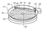
- FIG. 2 is a perspective view of an upper sorting chamber showing a characteristic part of the present invention in the cylindrical sieve device of FIG. 1.
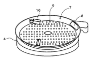
- FIG. 3 is a schematic plan view of the upper sorting chamber of FIG. 2 showing an example of the flow state of the granular material in the present invention. It is a perspective view of the upper sorting room which shows an example of a prior art.
- FIG. 1 shows a cylindrical sieving device 1 according to an embodiment of the present invention, showing an overall configuration common to the prior art as described above.
- an upper sorting chamber 22 is formed in a sieve frame 21 having a circular planar shape, and a predetermined size different from that of the porous plate 23 is formed in the central portion of the upper sorting chamber 22.
- the flat plate part 25 without the holes 24 is provided.
- the granular material having a length corresponding to the coarse particle is arranged in the longitudinal direction of the eyes (holes) 24 of the porous plate 23. The phenomenon of passing through the eyes (holes) 24 as it is by being thrown in a posture directed in the direction is suppressed.
- the raw material granular material 3 introduced from the granular material inlet 2 as shown in FIG. 1 is added by the vibration means 5 (FIG. 1) in the sieve frame 21 (FIG. 2).
- the vibrating perforated plate 23 (FIG. 2) having the holes 24 of a predetermined size to be shaken, coarse particles are sorted into other granular materials (a granular material including normal particles of normal size and powder targeted). Is done.
- the selected coarse particles are discharged from the coarse particle discharge port 26 (FIG. 2), and the granular material 9 (FIG. 1) after the coarse particles are removed is, as described above, the lower middle sorting chamber 10 (FIG. 1). ) And is sorted into normal grains and powder in the middle sorting chamber 10.
- the normal particles sorted in the middle sorting chamber 10 are discharged from the normal particle discharge port 12 (FIG. 1), the powder 13 (FIG. 1) is dropped into the lower chamber 14 (FIG. 1), and the powder discharge port 15 (FIG. 1). ) Is discharged.
- the angle can be adjusted in the upper sorting chamber 22 so that one end of the sieve frame 21 is positioned at one end side in the circumferential direction of the sieve frame 21 of the coarse grain outlet 26.
- a rectifying plate 28 is provided which is connected via the connecting portion 27 and extends longer than the radius of the circular sieve frame 21.
- the material of the current plate 28 is not particularly limited, but it is desirable to use a material that can withstand friction with the powder particles.
- the current plate 28 extends so as to incline toward the region A (shown in FIG. 3) including the coarse grain outlet 26 with respect to the direction of the diameter 29 (shown in FIG. 3) passing through the center C of the circular sieve frame 21. Has been placed.
- a region B (shown in FIG. 3) including the center C of the circular sieve frame in the upper sorting chamber defined by the flow straightening plate 28.
- a granular material channel port 30 Through which the granular material on the porous plate 23 can move.
- the width W (illustrated in FIG. 3) of the granular material channel port 30 is set to 3% or more of the diameter of the circular sieve frame 21.
- a slide mechanism capable of adjusting the position of the tip portion is provided on the tip side of the powder passage opening 30 of the rectifying plate 28, and this slide mechanism adjusts the length of the rectifying plate 28.
- a possible rectifying plate length adjusting mechanism 31 is configured. Further, in this embodiment, a part of the rectifying plate length adjusting mechanism 31 is extended to the forming part of the powder channel opening 30, and the rectifying plate length adjusting mechanism 31 is adjusted along the extending part 32. By doing so, the width
- the anti-rectifying plate 28 side portion of the granular material channel port 30, that is, the anti-rectifying plate 28 side portion of the extension portion 32 is connected to the sieve frame 21 via the connection portion 33, and through the connection, Finally, the arrangement of the rectifying plate 28 and the position of the granular material flow passage port 30 are determined.
- the length of the current plate 28 arranged as described above may be longer than the radius of the circular sieve frame 21 as described above, but is desirably set to 70% or more of the diameter of the circular sieve frame 21.
- the distance L between the outer periphery of the flat plate portion 25 provided at the central portion in the sieve frame 21 and the rectifying plate 28 is, for example, in a range of about ⁇ 9% to 15% with respect to the diameter of the sieve frame 21. (A minus sign indicates a state in which the rectifying plate 28 is disposed on the flat plate portion 25).
- Cylindrical vibratory sieve device having a structure as shown in FIG. 1 is selected by compounding a reinforcing agent, an additive, and a colorant into a PPS (polyphenylene sulfide) resin and cutting.
- PPS polyphenylene sulfide
- a technical baffle was provided and tested as follows.
- the raw material pellets as a granular material were supplied at a rate of about 8400 g / min using a cylindrical sieve device having a sieve frame diameter of 615 mm, and a sorting process was performed.
- Example 1 As an installation condition of the current plate, the angle is 22 ° from the current plate attachment position and the line passing through the center of the screen, and the length is 90.2% (555 mm) with respect to the diameter of the screen frame of the cylindrical screen device.
- the flow path width of the resin pellet (width of the granular material flow path opening) is 3.3% (20 mm) with respect to the diameter of the sieve frame of the cylindrical sieve device. It was found that 6.5% (40 mm) is suitable for the distance to the diameter of the sieve frame.
- the PPS resin is introduced from the powder and material inlet, starts moving by vibration on the punching metal, and moves while contacting the punching metal and the current plate.
- Example 2 Comparative Example 2
- the installation angle of the current plate is 22 ° to 4.5 °, and the length is 90.2% (555 mm) to 97.8% (601 mm) with respect to the diameter of the sieve frame of the cylindrical sieve device.
- the distance between the outer periphery of the flat plate part without punch holes at the center of the sieve frame and the current plate is 6.5% (40 mm) to -8.1% (-50 mm) with respect to the diameter of the sieve frame, was selected in the same manner as in Example 1 at three levels of 1.6% (10 mm), 3.3% (20 mm), and 7.3% (45 mm) with respect to the diameter of the sieve frame.
- Example 3 Comparative Example 3
- the installation angle of the current plate is 22 ° to 11 °, and the length is 90.2% (555 mm) to 96.7% (595 mm) with respect to the diameter of the sieve frame of the cylindrical vibration sieve device.
- the distance between the outer periphery of the flat plate part without punch holes at the center of the sieve frame and the current plate is 6.5% (40 mm) to 0% (0 mm) with respect to the diameter of the sieve frame, and the width of the powder channel opening is set to the sieve frame.
- Selection in the same manner as in Example 1 at four levels of 1.6% (10 mm), 3.3% (20 mm), 7.3% (45 mm), and 11.4% (70 mm) went.
- Example 4 Comparative Example 4 Compared to Example 1, the installation angle of the current plate is 22 ° to 17.5 °, and the length is 90.2% (555 mm) to 94.3% (580 mm) with respect to the diameter of the sieve frame of the cylindrical vibration sieve device.
- the distance between the outer periphery of the flat plate portion without punch holes in the central portion of the sieve frame and the current plate is 6.5% (40 mm) to 4.9% (30 mm) with respect to the diameter of the sieve, and the width of the granular material channel opening
- this level was set to Comparative Example 4. Under conditions other than the above levels, the amount of normal grains discharged from the coarse grain outlet was significantly reduced compared to Comparative Example 1. The results are shown in Table 3.
- Example 5 Comparative Example 5
- the width of the powder channel opening was changed to three levels of 1.6% (10 mm), 7.3% (45 mm), and 11.4% (70 mm) with respect to the diameter of the sieve frame. Except for the above, selection was performed in the same manner as in Example 1 under the same conditions as in Example 1. As a result, when the width of the granular material flow passage opening was 1.6% of the diameter of the sieve frame, the width of the granular flow passage opening was too narrow, so that the processing could not be completed and clogging occurred, causing overflow. Therefore, this level was set as Comparative Example 5. Under conditions other than the above levels, the amount of normal grains discharged from the coarse grain outlet was significantly reduced compared to Comparative Example 1. The results are shown in Table 4.
- Example 6 Comparative Example 6
- the installation angle of the current plate is 22 ° to 28.5 °, and the length is 90.2% (555 mm) to 85.4% (525 mm) with respect to the diameter of the sieve frame of the cylindrical vibration sieve device. )
- the distance between the outer periphery of the flat plate portion without punch holes in the central portion of the sieve frame and the current plate is 6.5% (40 mm) to 11.4% (70 mm) with respect to the diameter of the sieve frame, and the width of the flow passage opening is set to Sorting was performed in the same manner as in Example 1 at three levels of 1.6% (10 mm), 3.3% (20 mm), and 7.3% (45 mm).
- the cylindrical sieving apparatus according to the present invention is used for the selection process in the compound production of the thermoplastic resin.
- the processing object to be selected by the cylindrical sieving apparatus according to the present invention Is not limited to a thermoplastic resin compound, and can be applied to sorting objects in all other fields.
- the cylindrical sieving apparatus according to the present invention and the method of selecting a granular material using the cylindrical sieving apparatus can be applied to the selection of any granular material that is required to reduce the amount of normal particles discharged to the coarse particle outlet, and as a whole device The yield of normal grains can be greatly improved.
Landscapes
- Engineering & Computer Science (AREA)
- Mechanical Engineering (AREA)
- Combined Means For Separation Of Solids (AREA)
- Processing And Handling Of Plastics And Other Materials For Molding In General (AREA)
Abstract
振動多孔板と粗大粒排出口が設けられた上部選別室を有する円筒型篩装置において、上部選別室内に、円形の篩枠の半径よりも長く延びる整流板を設け、該整流板を、篩枠の中心を通る方向に対し粗大粒排出口を含む領域側に傾けて配置し、整流板の延長線上に、整流板により区画された両側の領域間に多孔板上の粉粒体を移動可能な粉粒体流路口を設け、該粉粒体流路口の幅を、円形の篩枠の直径の3%以上に設定したことを特徴とする円筒型篩装置、およびそれを用いた粉粒体の選別方法。粗大粒とともに排出される正常粒の量を大幅に低減することができ、正常粒を製品とする場合の歩留まりを大幅に向上できる。
Description
本発明は、円筒型篩装置およびそれを用いた粉粒体の選別方法に関し、とくに、選別された粗大粒とともに排出される正常粒の量を低減し、正常粒の採取収率を高めるようにした円筒型篩装置およびそれを用いた粉粒体の選別方法に関する。
粉粒体としての樹脂ペレットは、例えば、熱可塑性樹脂に強化剤や着色剤などをコンパウンドし付加価値を新たに加えた樹脂のペレットは、口金の吐出口から押出、成形された長尺の樹脂を、長さ方向に対して垂直方向に切断することで製造される。切断された粒状の樹脂は総称して「樹脂ペレット」と呼ばれ、各種分野において、例えば、自動車や電気部品の分野において、成形加工原料として使用される。
このような樹脂ペレットの切断面の形状は吐出口の形状によって決まるため安定しているが、長さ方向の形状(サイズ)については、材料の特性や切断条件によって形状不良ペレットが生じてしまうことがある。
形状不良ペレットは成形機内部への不安定なフィードを誘発し成形工程上大きな影響を与えるため、ペレット形状のばらつきをある程度の範囲内に抑える必要がある。ばらつきを抑え、サイズがある程度の範囲内に納められたペレットを得るためには、サイズに関して、とくにペレットの長さに関して、正常粒とそれ以外とに選別することが有効である。
発生した形状不良ペレットを選別する方法としては、振動篩装置によって投入ペレットを長さに応じて篩分けする方法が挙げられる。振動篩装置としては、例えば、投入材料を篩分けする所定の目開きのパンチングメタル(多孔板)と、該パンチングメタルを加振する加振手段を有し、篩分け対象となる材料をパンチングメタル上に投入する振動篩装置が知られている(例えば、特許文献1~7)。
この種の振動篩装置としては、例えば図1に示すような円筒型篩装置が知られている(図1に示す円筒型篩装置は、従来技術の説明と本発明の説明とに共通して用いる)。図1に示す円筒型篩装置1においては、粉粒体投入口2から投入された原料粉粒体3を、篩枠4内に加振手段5により加振される所定の目開きのパンチングメタル(多孔板)6が設けられた上部選別室7内で粗大粒をそれ以外の粉粒体(目標とする正常サイズの正常粒と紛体とを含む粉粒体)とに選別し、選別された粗大粒を粗大粒排出口8から排出するようになっている。主として粗大粒が除去された後の粉粒体9は、下方の中部選別室10に落下され、上記パンチングメタル(多孔板)6よりも小さい目開きの加振パンチングメタル(多孔板)11上で、正常粒と紛体とに選別され、正常粒は正常粒排出口12から排出され、紛体13は下部室14に落下され、紛体排出口15から排出されるようになっている。
このような従来の円筒型篩装置においては、例えば図4に示すように、上部選別室7内において、投入された原料粉粒体を極力万遍なくパンチングメタル6上に分布させ、パンチングメタル6による選別処理に供することができるように、パンチングメタル6上での原料粉粒体の流動を制御する整流板16を、篩枠4の内周面から内方に向けて短く延びるように設ける構造が知られている(例えば、特許文献1、2、5)。
ところが、図4に示したような従来の円筒型篩装置において、篩枠4の内周面から内方に向けて短く延びる整流板16を設けるだけでは、パンチングメタル6上で原料粉粒体を均一に分布させる効果が不十分であるのに加え、原料粉粒体の投入部から粗大粒排出口8までの流動距離が短いため、粗大粒排出口8からは選別された粗大粒とともに選別が十分に行われなかった正常粒が排出されてしまう。粗大粒排出口8からの正常粒の排出量が多くなると、篩装置全体による選別における正常粒の採取収率が低くなり、正常粒が採取製品である場合の歩留まりが悪化することとなる。
そこで本発明の課題は、上記のような従来の篩装置における問題点に着目し、粗大粒とともに排出される正常粒の量を大幅に低減することができ、正常粒を製品とする場合の歩留まりを大幅に向上可能な円筒型篩装置と、それを用いた粉粒体の選別方法を提供することにある。
上記課題を解決するために、本発明に係る円筒型篩装置は、上部に、平面形状が円形の篩枠内に該篩枠内の中央部に投入された原料粉粒体を粗大粒とそれ以外の粉粒体とに選別可能な振動多孔板が設けられているとともに、前記篩枠に前記多孔板上で選別された粗大粒を排出する粗大粒排出口が設けられた上部選別室を有する円筒型篩装置において、前記上部選別室内に、一方の端部が前記篩枠の前記粗大粒排出口の篩枠周方向一端側の位置に接続され、円形の篩枠の半径よりも長く延びる整流板を設け、該整流板を、円形の篩枠の中心を通る方向に対し前記粗大粒排出口を含む領域側に傾いて延びるように配置するとともに、前記上部選別室内の前記整流板の他方の端部の延長線上に、前記整流板により区画された前記上部選別室内の円形の篩枠の中心を含む領域から前記粗大粒排出口を含む領域へと前記多孔板上の粉粒体が移動可能な粉粒体流路口を設け、該粉粒体流路口の幅を、円形の篩枠の直径の3%以上に設定したことを特徴とするものからなる。
このような本発明に係る円筒型篩装置においては、上部選別室の篩枠内の中央部に原料粉粒体が投入され、投入された原料粉粒体は、所定のサイズの目が開孔された多孔板(例えば、パンチングメタル)の振動により、該多孔板の目を通過しない粗大粒と、多孔板の目を通過する正常粒を含む粉粒体とに選別される。選別された粗大粒は、粗大粒排出口から排出されるが、このとき、選別が不十分であった正常粒も粗大粒排出口から排出されようとする。しかし本発明においては、上部選別室内に、上記のような、一方の端部が篩枠の粗大粒排出口の篩枠周方向一端側の位置に接続され、円形の篩枠の半径よりも長く延びる整流板が、円形の篩枠の中心を通る方向に対し粗大粒排出口を含む領域側に傾いて延びるように配置されており、かつ、整流板の他方の端部の延長線上に粉粒体流路口が設けられている。したがって、多孔板上の粉粒体は、投入された上部選別室の篩枠内の中央部から粗大粒排出口に向けて短絡的に流動することはなく、整流板により案内され、すなわち、整流板により区画された上部選別室内の円形の篩枠の中心を含む領域から、粉粒体流路口を通して、上記粗大粒排出口を含む領域へと上記多孔板上を案内され、しかる後に粗大粒排出口に向けて流動して、該粗大粒排出口から選別された粗大粒を含む形態にて排出される経路を辿る。このように、特定の整流板によって、正常粒の粗大粒排出口への短絡的な移動が阻止されるとともに、粉粒体の多孔板上での進行経路(流動経路)が長くなるため、多孔板上での粉粒体の層厚みが均一化され、粉粒体の多孔板への接触時間が長くなり、粗大粒と正常粒等との選別効率が高められ、粗大粒排出口まで選別されずに流動されてしまう正常粒の量が大幅に低減される。その結果、粗大粒とともに粗大粒排出口から排出される正常粒の量が大幅に低減され、本装置における正常粒の採取収率が大幅に高められる。また、本発明では、整流板の先端側に設けられる上記粉粒体流路口の幅が、円形の篩枠の直径の3%以上に設定されているので、多孔板上を流動しようとしている粉粒体が該粉粒体流路口を通過し切れずにその部位で詰まりを発生してオーバーフローを引き起こす不都合な現象も回避され、上述の如き正常粒の採取収率の大幅な向上が確実に達成されることとなっている。
上記本発明に係る円筒型篩装置においては、上記粗大粒排出口が、篩枠の周方向の複数箇所に設けられている形態を採ることも可能であるが、篩枠の周方向に1箇所だけ設けられている形態を採用することが好ましい。1箇所だけに設けられていることにより、上記のような整流板による作用、効果がより確実に得られる。
また、上記整流板の長さについては、円形の篩枠の半径よりも長いことが必要であるが、さらに、上記篩枠への接続位置から上記粉粒体流路口の一端までの長さとして、円形の篩枠の直径の70%以上に設定されていることが好ましい。整流板の長さをこのように設定することにより、前述のような整流板による作用、効果がより確実に得られる。但し、整流板の先端側に設けられる上記粉粒体流路口の幅が、円形の篩枠の直径の3%以上に設定されることが前提となる。
また、上記整流板は、円形の篩枠の中心を通る方向に対し粗大粒排出口を含む領域側に傾いて延びるように配置されるが、このとき、整流板は、篩枠への接続位置と円形の篩枠の中心とを通る篩枠の直径方向に対し、5~28度の角度範囲内に配置されていることが好ましい。このような角度範囲内に整流板を配置することにより、多孔板上を案内される粉粒体の振動多孔板による良好な選別機能を発揮可能な領域を確保できるとともに、多孔板上を案内される粉粒体の多孔板との接触時間を長く確保でき、振動多孔板による選別機能自体の向上をはかることができる。
また、本発明に係る円筒型篩装置においては、上部選別室の篩枠内の中央部に、上記多孔板とは異なる孔の無い平板部が設けられていることが好ましい。このような平板部が設けられていることにより、篩枠内の中央部に投入された原料粉粒体のうち、粗大粒に相当する長さを有する粒体が、その長手方向を多孔板の目の方向に向けた姿勢で投入されることにより多孔板によって選別されることなく目を通過してしまう現象を抑えることができ、上部選別室内における選別効率の低下を抑制できる。
また、整流板の長さの最適値が求められている場合には、整流板の長さをその最適値に設定すればよいが、選別対象原料粉粒体の種類やロットが変更された場合、長さの最適値が変化する可能性がある。このような場合に対応するためには、整流板の前記粉粒体流路口の一端側部分に、整流板の長さを調整可能な整流板長さ調整機構が設けられていることが好ましい。このような長さ調整機構が設けられていると、整流板の長さを必要に応じて最適な長さに容易に調整することができる。前述の整流板の、篩枠への接続位置と円形の篩枠の中心とを通る篩枠の直径方向に対する角度に関しても、例えば整流板の篩枠への接続位置に整流板の角度を調整可能な整流板角度調整機構を設けておくと、整流板の角度についても必要に応じて最適な角度に容易に調整することができるようになる。
また、上記整流板長さ調整機構が、整流板の先端側に設けられる粉粒体流路口の幅の調整機構を兼ねていると、整流板の長さと粉粒体流路口の幅を同時に最適値に調整することが可能になる。
また、本発明に係る円筒型篩装置においては、前述の図1に示したように、上記上部選別室の下部に、該上部選別室内で選別された粗大粒が除去された後の粉粒体を取り出し可能な粉粒体取得室、または、上記上部選別室内で選別された粗大粒が除去された後の粉粒体をさらに振動多孔板により目標範囲内のサイズの正常粒とそれ未満のサイズの紛体とに選別可能な中部選別室を有する構成を採用することができる。さらに、中部選別室の下部に粉体を取り出し可能な下部室を設けることもできる。必要に応じて設置室を決めればよい。
なお、本発明に係る円筒型篩装置で選別対象とする投入原料粉粒体の種類は、特に限定されないが、本発明に係る円筒型篩装置は、例えば、所定長に切断された樹脂ペレット(樹脂以外の成分を含有する複合材料のペレットを含む)の選別に用いて最適なものである。
本発明は、上記のような円筒型篩装置を用いて粉粒体を選別する粉粒体の選別方法についても提供する。この本発明に係る粉粒体の選別方法も、例えば、所定長に切断された樹脂ペレット(樹脂以外の成分を含有する複合材料のペレットを含む)の選別に用いて最適なものである。
本発明に係る円筒型篩装置およびそれを用いた粉粒体の選別方法によれば、上部選別室内に特定の整流板を特定の配置形態にて設け、振動多孔板上で投入原料粉粒体を多孔板との長い接触時間をもって案内するとともに、整流板で区画された両側の領域間に粉粒体を流動させる粉粒体流路口の幅を特定幅以上に設定したので、選別された粗大粒とともに粗大粒排出口から排出される正常粒の量を大幅に低減することができ、本装置における正常粒の採取収率を大幅に高めることができる。
以下に、本発明の実施の形態について、図面を参照しながら説明する。
図1は、前述したように、従来技術と共通する全体構成を示す、本発明の一実施態様に係る円筒型篩装置1を示している。本実施態様においては、図2にも示すように、平面形状が円形の篩枠21内に上部選別室22が形成され、上部選別室22の中央部には、多孔板23とは異なる所定サイズの孔24の無い平板部25が設けられている。平板部25により、篩枠21内の中央部に投入された原料粉粒体のうち、粗大粒に相当する長さを有する粒体が、その長手方向を多孔板23の目(孔)24の方向に向けた姿勢で投入されることによりそのまま目(孔)24を通過してしまう現象が抑制される。
図1は、前述したように、従来技術と共通する全体構成を示す、本発明の一実施態様に係る円筒型篩装置1を示している。本実施態様においては、図2にも示すように、平面形状が円形の篩枠21内に上部選別室22が形成され、上部選別室22の中央部には、多孔板23とは異なる所定サイズの孔24の無い平板部25が設けられている。平板部25により、篩枠21内の中央部に投入された原料粉粒体のうち、粗大粒に相当する長さを有する粒体が、その長手方向を多孔板23の目(孔)24の方向に向けた姿勢で投入されることによりそのまま目(孔)24を通過してしまう現象が抑制される。
上部選別室22では、図1に示したような粉粒体投入口2から投入された原料粉粒体3が、篩枠21(図2)内で、加振手段5(図1)により加振される所定サイズの孔24を有する振動多孔板23(図2)によって、粗大粒をそれ以外の粉粒体(目標とする正常サイズの正常粒と紛体とを含む粉粒体)とに選別される。選別された粗大粒は粗大粒排出口26(図2)から排出され、粗大粒が除去された後の粉粒体9(図1)は、前述の如く、下方の中部選別室10(図1)に落下され、中部選別室10内で正常粒と紛体とに選別される。中部選別室10内で選別された正常粒は正常粒排出口12(図1)から排出され、紛体13(図1)は下部室14(図1)に落下され、紛体排出口15(図1)から排出される。
本実施態様では、図2に示すように、上部選別室22内に、一方の端部が篩枠21の、粗大粒排出口26の篩枠21周方向一端側の位置に、角度調整可能な接続部27を介して接続され、円形の篩枠21の半径よりも長く延びる整流板28が設けられている。整流板28の材質は特に限定しないが粉粒体との摩擦に耐えうる素材を用いることが望ましい。整流板28は、円形の篩枠21の中心Cを通る直径29(図3に図示)の方向に対し、粗大粒排出口26を含む領域A(図3に図示)側に傾いて延びるように配置されている。上部選別室22内の上記整流板28の他方の端部の延長線上には、整流板28により区画された上記上部選別室内の円形の篩枠の中心Cを含む領域B(図3に図示)から上記粗大粒排出口26を含む領域Aへと多孔板23上の粉粒体が移動可能な粉粒体流路口30が設けられている。この粉粒体流路口30の幅W(図3に図示)は、円形の篩枠21の直径の3%以上に設定されている。本実施態様では、整流板28の粉粒体流路口30の先端側に、その先端部の位置を調整可能なスライド機構が設けられており、このスライド機構が、整流板28の長さを調整可能な整流板長さ調整機構31を構成している。また、本実施態様では、整流板長さ調整機構31の一部が、粉粒体流路口30の形成部まで延長されており、該延長部32に沿って整流板長さ調整機構31を調整することにより、粉粒体流路口30の幅も調整できるようになっている。粉粒体流路口30の反整流板28側部位、つまり、上記延長部32の反整流板28側部位は、接続部33を介して篩枠21に接続されており、その接続を介して、最終的に、整流板28の配置、粉粒体流路口30の位置が決められている。
上記のように配置される整流板28の長さは、上述の如く、円形の篩枠21の半径よりも長ければよいが、望ましくは、円形の篩枠21の直径の70%以上に設定される。また、図3に示すように、整流板28の傾き配置に関しては、篩枠21への接続位置27と円形の篩枠21の中心Cとを通る篩枠21の直径29方向に対する角度θとして、5~28度の角度範囲内に配置されていることが好ましい。さらに、篩枠21内の中央部に設けられた平板部25の外周と整流板28との間の距離Lとしては、例えば、篩枠21の直径に対し-9%~15%程度の範囲内にあることが好ましい(マイナス表示は整流板28が平板部25上に配置されている状態を示す)。
以下、本発明を実施例によってさらに具体的に説明する。
PPS(ポリフェニレンサルファイド)樹脂に強化剤、添加剤、着色剤をコンパウンドし、カッティングして得られた粉粒体の選別を、図1に示すような構成を有する円筒型振動篩装置(晃栄産業株式会社佐藤式ふるい機、上段パンチングメタルφ5mm×P(ピッチ)8mm(中央部平板部φ160mm)、下段メッシュφ0.71mm×P1.41mm×12メッシュ)を用い、且つ、上部選別室に、実施例1~6、比較例2~6においては図2、図3に示したような整流板(材質:SUS304)、粉粒体流路口を設け、比較例1においては図4に示したような従来技術の整流板を設けて、以下のように試験した。
PPS(ポリフェニレンサルファイド)樹脂に強化剤、添加剤、着色剤をコンパウンドし、カッティングして得られた粉粒体の選別を、図1に示すような構成を有する円筒型振動篩装置(晃栄産業株式会社佐藤式ふるい機、上段パンチングメタルφ5mm×P(ピッチ)8mm(中央部平板部φ160mm)、下段メッシュφ0.71mm×P1.41mm×12メッシュ)を用い、且つ、上部選別室に、実施例1~6、比較例2~6においては図2、図3に示したような整流板(材質:SUS304)、粉粒体流路口を設け、比較例1においては図4に示したような従来技術の整流板を設けて、以下のように試験した。
以下に、実施例および比較例を挙げて本発明について具体的に説明するが、本発明はこれらの実施例のみに限定されるものではない。また、以下の実施例および比較例において[%]は、特に断りのない限り質量基準である。
なお、以下の実施例、比較例では、篩枠直径615mmの円筒型篩装置を用いて、約8400g/minで粉粒体としての原料ペレットを供給し、選別処理を行った。また、排出口から排出された粉粒体の評価基準は、粗大粒=長径、短径、長さのいずれかが1つでも5.1mm以上であった場合、正常粒=長径、短径、長さの3つ全てが5.0mm以下であったペレットをピンセットで分けて評価し、残ったものを粉体とした。
まず、円筒型振動篩装置の運転開始から30秒後篩パンチングメタル上へPPS樹脂の供給を開始した。粉粒体投入口からPPS樹脂を篩パンチングメタル上に一定量を連続的に供給し、粗大粒、正常粒、粉体の選別を一定時間行った。上段篩目(大)を通過しなかった選別対象物は、粗大粒排出口より採取した。上段篩目(大)を通過し且つ、下段篩目(小)を通過しなかった選別対象物は正常粒排出口より採取した。上段篩目(大)を通過し且つ、下段篩目(小)も通過した選別対象物は紛体排出口より各々採取した。
[実施例1]
整流板の取付け条件として、角度は整流板取り付け位置から篩の中心を通る線との成す角度を22°、長さは円筒型篩装置の篩枠の直径に対し90.2%(555mm)、樹脂ペレットの流路幅(粉粒体流路口の幅)は円筒型篩装置の篩枠の直径に対し3.3%(20mm)、篩枠中央部のパンチ孔無し平板部の外周と整流板との距離は篩枠の直径に対し6.5%(40mm)が好適であることを見出した。PPS樹脂は粉粒体投入口より投入されパンチングメタル上で振動により運動を始めパンチングメタル及び整流板に接触しながら移動する。このとき整流板を設けていることにより、下記比較例1に比べ、粉流体のパンチングメタルへの接触時間が飛躍的に延び、パンチングメタル中心部付近での処理量が増加し正常粒が粗大粒排出口まで移動し排出されることが顕著に減少した。さらに、PPS樹脂の進行経路が延びたことによりパンチングメタルでの層厚みが平均化し、正常粒排出口での粗大粒排出量の絶対量も減少した。下段のメッシュ部での選別では、上部パンチングメタル中心部付近での処理量向上に伴い正常粒排出口への紛体の排出量の絶対量が減少した。長時間運転でも篩の処理能力の低下は起きない。結果を表1に示す。
整流板の取付け条件として、角度は整流板取り付け位置から篩の中心を通る線との成す角度を22°、長さは円筒型篩装置の篩枠の直径に対し90.2%(555mm)、樹脂ペレットの流路幅(粉粒体流路口の幅)は円筒型篩装置の篩枠の直径に対し3.3%(20mm)、篩枠中央部のパンチ孔無し平板部の外周と整流板との距離は篩枠の直径に対し6.5%(40mm)が好適であることを見出した。PPS樹脂は粉粒体投入口より投入されパンチングメタル上で振動により運動を始めパンチングメタル及び整流板に接触しながら移動する。このとき整流板を設けていることにより、下記比較例1に比べ、粉流体のパンチングメタルへの接触時間が飛躍的に延び、パンチングメタル中心部付近での処理量が増加し正常粒が粗大粒排出口まで移動し排出されることが顕著に減少した。さらに、PPS樹脂の進行経路が延びたことによりパンチングメタルでの層厚みが平均化し、正常粒排出口での粗大粒排出量の絶対量も減少した。下段のメッシュ部での選別では、上部パンチングメタル中心部付近での処理量向上に伴い正常粒排出口への紛体の排出量の絶対量が減少した。長時間運転でも篩の処理能力の低下は起きない。結果を表1に示す。
[比較例1]
本発明による整流板を設けず、図4に示した従来技術による整流板2枚を備える円筒型振動篩装置を使用して選別を行った。つまり、本発明による整流板を設けていないため、本発明を適用していない構成の円筒型振動篩装置である。結果、上部選別室においてPPS樹脂がパンチングメタルと接触する時間が短く、粗大粒排出口へ正常粒が直行する傾向が見られた。粗大粒排出口での正常品排出量は実施例1と比較したとき89.5%増加し、選別精度が不充分であることが判明した。
本発明による整流板を設けず、図4に示した従来技術による整流板2枚を備える円筒型振動篩装置を使用して選別を行った。つまり、本発明による整流板を設けていないため、本発明を適用していない構成の円筒型振動篩装置である。結果、上部選別室においてPPS樹脂がパンチングメタルと接触する時間が短く、粗大粒排出口へ正常粒が直行する傾向が見られた。粗大粒排出口での正常品排出量は実施例1と比較したとき89.5%増加し、選別精度が不充分であることが判明した。
また、正常粒排出口での粗大粒の混入量は、実施例1と比較したとき21.4%増加し、選別精度が不充分であることが判明した。
また、正常粒排出口での紛体の混入量は、実施例1と比較したとき29.4%増加し、選別精度が不充分であることが判明した。結果を表1に示す。
[実施例2、比較例2]
実施例1に対して、整流板の設置角度を22°から4.5°、長さを円筒型篩装置の篩枠の直径に対し90.2%(555mm)から97.8%(601mm)、篩枠中央部のパンチ孔無し平板部の外周と整流板との距離は篩枠の直径に対し6.5%(40mm)から-8.1%(-50mm)とし、粉粒体流路口の幅を篩枠の直径に対し1.6%(10mm)、3.3%(20mm)、7.3%(45mm)の3水準にて実施例1と同様な方法で選別を行った。結果、粉粒体流路口の幅が篩枠の直径に対し1.6%では、粉粒体流路口の幅が狭すぎたため処理しきれず詰まりが発生し、オーバーフローを引き起こした。したがって、この水準は比較例2とした。粉粒体流路口の幅を篩枠の直径に対し3.3%(20mm)、7.3%(45mm)の水準では、実施例1ほどではないにしても、比較例1に比べ、粗大粒排出口からの正常粒の排出量は大幅に減少することができた。結果を表1に示す。
実施例1に対して、整流板の設置角度を22°から4.5°、長さを円筒型篩装置の篩枠の直径に対し90.2%(555mm)から97.8%(601mm)、篩枠中央部のパンチ孔無し平板部の外周と整流板との距離は篩枠の直径に対し6.5%(40mm)から-8.1%(-50mm)とし、粉粒体流路口の幅を篩枠の直径に対し1.6%(10mm)、3.3%(20mm)、7.3%(45mm)の3水準にて実施例1と同様な方法で選別を行った。結果、粉粒体流路口の幅が篩枠の直径に対し1.6%では、粉粒体流路口の幅が狭すぎたため処理しきれず詰まりが発生し、オーバーフローを引き起こした。したがって、この水準は比較例2とした。粉粒体流路口の幅を篩枠の直径に対し3.3%(20mm)、7.3%(45mm)の水準では、実施例1ほどではないにしても、比較例1に比べ、粗大粒排出口からの正常粒の排出量は大幅に減少することができた。結果を表1に示す。

[実施例3、比較例3]
実施例1に対して、整流板の設置角度を22°から11°、長さを円筒型振動篩装置の篩枠の直径に対し90.2%(555mm)から96.7%(595mm)、篩枠中央部のパンチ孔無し平板部の外周と整流板との距離は篩枠の直径に対し6.5%(40mm)から0%(0mm)とし、粉粒体流路口の幅を篩枠の直径に対し1.6%(10mm)、3.3%(20mm)、7.3%(45mm)、11.4%(70mm)の4水準にて実施例1と同様な方法で選別を行った。結果、粉粒体流路口の幅が篩枠の直径に対し1.6%の水準では、粉粒体流路口の幅が狭すぎたため処理しきれず詰まりが発生し、オーバーフローを引き起こした。したがって、この水準は比較例3とした。上記水準以外の条件では比較例1に対して粗大粒排出口からの正常粒の排出量は大幅に減少することができた。結果を表2に示す。
実施例1に対して、整流板の設置角度を22°から11°、長さを円筒型振動篩装置の篩枠の直径に対し90.2%(555mm)から96.7%(595mm)、篩枠中央部のパンチ孔無し平板部の外周と整流板との距離は篩枠の直径に対し6.5%(40mm)から0%(0mm)とし、粉粒体流路口の幅を篩枠の直径に対し1.6%(10mm)、3.3%(20mm)、7.3%(45mm)、11.4%(70mm)の4水準にて実施例1と同様な方法で選別を行った。結果、粉粒体流路口の幅が篩枠の直径に対し1.6%の水準では、粉粒体流路口の幅が狭すぎたため処理しきれず詰まりが発生し、オーバーフローを引き起こした。したがって、この水準は比較例3とした。上記水準以外の条件では比較例1に対して粗大粒排出口からの正常粒の排出量は大幅に減少することができた。結果を表2に示す。

[実施例4、比較例4]
実施例1に対して、整流板の設置角度を22°から17.5°、長さを円筒型振動篩装置の篩枠の直径に対し90.2%(555mm)から94.3%(580mm)、篩枠中央部のパンチ孔無し平板部の外周と整流板との距離は篩の直径に対し6.5%(40mm)から4.9%(30mm)とし、粉粒体流路口の幅を篩枠の直径に対し1.6%(10mm)、3.3%(20mm)、7.3%(45mm)、11.4%(70mm)の4水準にて実施例1と同様な方法で選別を行った。結果、粉粒体流路口の幅が篩枠の直径に対し1.6%の水準では、粉粒体流路口の幅が狭すぎたため処理しきれず詰まりが発生し、オーバーフローを引き起こした。したがって、この水準は比較例4とした。上記水準以外の条件では比較例1に対して粗大粒排出口からの正常粒の排出量は大幅に減少することができた。結果を表3に示す。
実施例1に対して、整流板の設置角度を22°から17.5°、長さを円筒型振動篩装置の篩枠の直径に対し90.2%(555mm)から94.3%(580mm)、篩枠中央部のパンチ孔無し平板部の外周と整流板との距離は篩の直径に対し6.5%(40mm)から4.9%(30mm)とし、粉粒体流路口の幅を篩枠の直径に対し1.6%(10mm)、3.3%(20mm)、7.3%(45mm)、11.4%(70mm)の4水準にて実施例1と同様な方法で選別を行った。結果、粉粒体流路口の幅が篩枠の直径に対し1.6%の水準では、粉粒体流路口の幅が狭すぎたため処理しきれず詰まりが発生し、オーバーフローを引き起こした。したがって、この水準は比較例4とした。上記水準以外の条件では比較例1に対して粗大粒排出口からの正常粒の排出量は大幅に減少することができた。結果を表3に示す。

[実施例5、比較例5]
実施例1に対して、粉粒体流路口の幅を篩枠の直径に対し1.6%(10mm)、7.3%(45mm)、11.4%(70mm)の3水準に変更した以外は実施例1と同じ条件のもと実施例1と同様な方法で選別を行った。結果、粉粒体流路口の幅が篩枠の直径に対し1.6%の水準では、粉粒体流路口の幅が狭すぎたため処理しきれず詰まりが発生し、オーバーフローを引き起こした。したがって、この水準は比較例5とした。上記水準以外の条件では比較例1に対して粗大粒排出口からの正常粒の排出量は大幅に減少することができた。結果を表4に示す。
実施例1に対して、粉粒体流路口の幅を篩枠の直径に対し1.6%(10mm)、7.3%(45mm)、11.4%(70mm)の3水準に変更した以外は実施例1と同じ条件のもと実施例1と同様な方法で選別を行った。結果、粉粒体流路口の幅が篩枠の直径に対し1.6%の水準では、粉粒体流路口の幅が狭すぎたため処理しきれず詰まりが発生し、オーバーフローを引き起こした。したがって、この水準は比較例5とした。上記水準以外の条件では比較例1に対して粗大粒排出口からの正常粒の排出量は大幅に減少することができた。結果を表4に示す。

[実施例6、比較例6]
実施例1に対して、整流板の設置角度を22°から28.5°、長さを円筒型振動篩装置の篩枠の直径に対し90.2%(555mm)から85.4%(525mm)、篩枠中央部のパンチ孔無し平板部の外周と整流板との距離は篩枠の直径に対し6.5%(40mm)から11.4%(70mm)とし、流路口の幅を篩の直径に対し1.6%(10mm)、3.3%(20mm)、7.3%(45mm)の3水準にて実施例1と同様な方法で選別を行った。結果、粉粒体流路口の幅が篩枠の直径に対し1.6%の水準では、粉粒体流路口の幅が狭すぎたため処理しきれず詰まりが発生し、オーバーフローを引き起こした。したがって、この水準は比較例6とした。上記水準以外の条件では比較例1に対して粗大粒排出口からの正常粒の排出量は大幅に減少することができた。結果を表5に示す。
実施例1に対して、整流板の設置角度を22°から28.5°、長さを円筒型振動篩装置の篩枠の直径に対し90.2%(555mm)から85.4%(525mm)、篩枠中央部のパンチ孔無し平板部の外周と整流板との距離は篩枠の直径に対し6.5%(40mm)から11.4%(70mm)とし、流路口の幅を篩の直径に対し1.6%(10mm)、3.3%(20mm)、7.3%(45mm)の3水準にて実施例1と同様な方法で選別を行った。結果、粉粒体流路口の幅が篩枠の直径に対し1.6%の水準では、粉粒体流路口の幅が狭すぎたため処理しきれず詰まりが発生し、オーバーフローを引き起こした。したがって、この水準は比較例6とした。上記水準以外の条件では比較例1に対して粗大粒排出口からの正常粒の排出量は大幅に減少することができた。結果を表5に示す。

なお、上述した実施例では、本発明に係る円筒型篩装置を熱可塑性樹脂のコンパウンド製造における選別工程に用いる例について説明したが、本発明に係る円筒型篩装置によって選別を行う処理対象物としては熱可塑性樹脂のコンパウンド品に限るものではなく、その他あらゆる分野の対象物の選別に適用することが可能である。
本発明に係る円筒型篩装置およびそれを用いた粉粒体の選別方法は、粗大粒排出口への正常粒の排出量の低減が求められるあらゆる粉粒体の選別に適用でき、装置全体としての正常粒の採取収率の大幅な向上をはかることができる。
1 円筒型篩装置
2 粉粒体投入口
3 原料粉粒体
4 篩枠
5 加振手段
6 多孔板 (パンチングメタル)
7 上部選別室
8 粗大粒排出口
9 粗大粒が除去された後の粉粒体
10 中部選別室
11 多孔板 (パンチングメタル)
12 正常粒排出口
13 紛体
14 下部室
15 紛体排出口
16 従来技術の整流板
21 篩枠
22 上部選別室
23 多孔板
24 孔
25 平板部
26 粗大粒排出口
27 接続部
28 整流板
29 円形の篩枠の中心を通る直径
30 粉粒体流路口
31 整流板長さ調整機構
32 延長部
33 接続部
A 粗大粒排出口を含む領域
B 円形の篩枠の中心を含む領域
C 円形の篩枠の中心
L 平板部の外周と整流板との距離
W 粉粒体流路口の幅
2 粉粒体投入口
3 原料粉粒体
4 篩枠
5 加振手段
6 多孔板 (パンチングメタル)
7 上部選別室
8 粗大粒排出口
9 粗大粒が除去された後の粉粒体
10 中部選別室
11 多孔板 (パンチングメタル)
12 正常粒排出口
13 紛体
14 下部室
15 紛体排出口
16 従来技術の整流板
21 篩枠
22 上部選別室
23 多孔板
24 孔
25 平板部
26 粗大粒排出口
27 接続部
28 整流板
29 円形の篩枠の中心を通る直径
30 粉粒体流路口
31 整流板長さ調整機構
32 延長部
33 接続部
A 粗大粒排出口を含む領域
B 円形の篩枠の中心を含む領域
C 円形の篩枠の中心
L 平板部の外周と整流板との距離
W 粉粒体流路口の幅
Claims (10)
- 上部に、平面形状が円形の篩枠内に該篩枠内の中央部に投入された原料粉粒体を粗大粒とそれ以外の粉粒体とに選別可能な振動多孔板が設けられているとともに、前記篩枠に前記多孔板上で選別された粗大粒を排出する粗大粒排出口が設けられた上部選別室を有する円筒型篩装置において、前記上部選別室内に、一方の端部が前記篩枠の前記粗大粒排出口の篩枠周方向一端側の位置に接続され、円形の篩枠の半径よりも長く延びる整流板を設け、該整流板を、円形の篩枠の中心を通る方向に対し前記粗大粒排出口を含む領域側に傾いて延びるように配置するとともに、前記上部選別室内の前記整流板の他方の端部の延長線上に、前記整流板により区画された前記上部選別室内の円形の篩枠の中心を含む領域から前記粗大粒排出口を含む領域へと前記多孔板上の粉粒体が移動可能な粉粒体流路口を設け、該粉粒体流路口の幅を、円形の篩枠の直径の3%以上に設定したことを特徴とする円筒型篩装置。
- 前記粗大粒排出口が、前記篩枠の周方向に1箇所だけ設けられている、請求項1に記載の円筒型篩装置。
- 前記整流板の、前記篩枠への接続位置から前記粉粒体流路口の一端までの長さが、円形の篩枠の直径の70%以上に設定されている、請求項1または2に記載の円筒型篩装置。
- 前記整流板が、前記篩枠への接続位置と円形の篩枠の中心とを通る篩枠の直径方向に対し、5~28度の角度範囲内に配置されている、請求項1~3のいずれかに記載の円筒型篩装置。
- 前記篩枠内の中央部に、前記多孔板とは異なる孔の無い平板部が設けられている、請求項1~4のいずれかに記載の円筒型篩装置。
- 前記整流板の前記粉粒体流路口の一端側部分に、整流板の長さを調整可能な整流板長さ調整機構が設けられている、請求項1~5のいずれかに記載の円筒型篩装置。
- 前記整流板長さ調整機構が前記粉粒体流路口の幅調整機構を兼ねている、請求項6に記載の円筒型篩装置。
- 前記上部選別室の下部に、該上部選別室内で選別された粗大粒が除去された後の粉粒体を取り出し可能な粉粒体取得室、または、前記上部選別室内で選別された粗大粒が除去された後の粉粒体をさらに振動多孔板により目標範囲内のサイズの正常粒とそれ未満のサイズの紛体とに選別可能な中部選別室を有する、請求項1~8のいずれかに記載の円筒型篩装置。
- 請求項1~8のいずれかに記載の円筒型篩装置を用いて粉粒体を選別する粉粒体の選別方法。
- 前記粉粒体が所定長に切断された樹脂ペレットである、請求項9に記載の粉粒体の選別方法。
Priority Applications (1)
| Application Number | Priority Date | Filing Date | Title |
|---|---|---|---|
| JP2015547579A JP6582990B2 (ja) | 2014-09-30 | 2015-09-15 | 円筒型篩装置およびそれを用いた粉粒体の選別方法 |
Applications Claiming Priority (2)
| Application Number | Priority Date | Filing Date | Title |
|---|---|---|---|
| JP2014200177 | 2014-09-30 | ||
| JP2014-200177 | 2014-09-30 |
Publications (1)
| Publication Number | Publication Date |
|---|---|
| WO2016052166A1 true WO2016052166A1 (ja) | 2016-04-07 |
Family
ID=55630208
Family Applications (1)
| Application Number | Title | Priority Date | Filing Date |
|---|---|---|---|
| PCT/JP2015/076088 Ceased WO2016052166A1 (ja) | 2014-09-30 | 2015-09-15 | 円筒型篩装置およびそれを用いた粉粒体の選別方法 |
Country Status (2)
| Country | Link |
|---|---|
| JP (1) | JP6582990B2 (ja) |
| WO (1) | WO2016052166A1 (ja) |
Cited By (7)
| Publication number | Priority date | Publication date | Assignee | Title |
|---|---|---|---|---|
| CN106076853A (zh) * | 2016-08-01 | 2016-11-09 | 王小琴 | 螺丝黏料挑选机 |
| CN108435539A (zh) * | 2018-03-19 | 2018-08-24 | 王华银 | 一种振动筛 |
| CN109865586A (zh) * | 2019-03-16 | 2019-06-11 | 方文星 | 一种化工物料高效分选方法 |
| WO2021010676A1 (ko) * | 2019-07-16 | 2021-01-21 | ㈜한국생명과학연구소 | 순환하는 유동체로 다양한 캡슐을 제조하는 캡슐제조장치 |
| CN112742518A (zh) * | 2020-12-17 | 2021-05-04 | 澧县绿能生物质科技有限公司 | 一种亚硫酸钠制备焙烧用滤渣回收处理装置 |
| CN113210254A (zh) * | 2021-05-19 | 2021-08-06 | 山西双良鼎新水泥有限公司 | 一种水泥加工用振动筛分设备及其水泥加工筛分方法 |
| JP2023172513A (ja) * | 2022-05-24 | 2023-12-06 | 住友金属鉱山株式会社 | 円形振動篩機、および粉体の篩別方法 |
Families Citing this family (1)
| Publication number | Priority date | Publication date | Assignee | Title |
|---|---|---|---|---|
| CN117259205B (zh) * | 2023-08-31 | 2025-08-26 | 吉林绿谷饲料有限公司 | 一种用于鸡饲料加工的原料筛选装置 |
Citations (5)
| Publication number | Priority date | Publication date | Assignee | Title |
|---|---|---|---|---|
| JPH07566U (ja) * | 1993-05-31 | 1995-01-06 | エヌオーケー株式会社 | 分級装置 |
| JP2000135474A (ja) * | 1998-08-24 | 2000-05-16 | Sekisui Plant System Kk | 振動篩装置 |
| JP2005305386A (ja) * | 2004-04-26 | 2005-11-04 | Mitsubishi Rayon Co Ltd | 粉体篩分方法 |
| JP2012217899A (ja) * | 2011-04-06 | 2012-11-12 | Mitsubishi Rayon Co Ltd | 振動ふるい機 |
| JP2013252493A (ja) * | 2012-06-07 | 2013-12-19 | Ricoh Co Ltd | 振動篩装置 |
Family Cites Families (5)
| Publication number | Priority date | Publication date | Assignee | Title |
|---|---|---|---|---|
| JP3013053B2 (ja) * | 1991-06-04 | 2000-02-28 | 澁谷工業株式会社 | ブラスト装置 |
| JPH1147692A (ja) * | 1997-07-30 | 1999-02-23 | Kowa Kogyosho:Kk | 振動分離装置 |
| GB2395923A (en) * | 2002-12-02 | 2004-06-09 | Russel Finex | Sieving apparatus |
| BE1019303A5 (nl) * | 2010-06-18 | 2012-05-08 | Smo Bvba | Inrichting en werkwijze voor het op grootte sorteren van bulkgoederen. |
| CN203556543U (zh) * | 2013-09-27 | 2014-04-23 | 江苏华亘泰来生物科技有限公司 | 一种改进的旋振筛 |
-
2015
- 2015-09-15 WO PCT/JP2015/076088 patent/WO2016052166A1/ja not_active Ceased
- 2015-09-15 JP JP2015547579A patent/JP6582990B2/ja active Active
Patent Citations (5)
| Publication number | Priority date | Publication date | Assignee | Title |
|---|---|---|---|---|
| JPH07566U (ja) * | 1993-05-31 | 1995-01-06 | エヌオーケー株式会社 | 分級装置 |
| JP2000135474A (ja) * | 1998-08-24 | 2000-05-16 | Sekisui Plant System Kk | 振動篩装置 |
| JP2005305386A (ja) * | 2004-04-26 | 2005-11-04 | Mitsubishi Rayon Co Ltd | 粉体篩分方法 |
| JP2012217899A (ja) * | 2011-04-06 | 2012-11-12 | Mitsubishi Rayon Co Ltd | 振動ふるい機 |
| JP2013252493A (ja) * | 2012-06-07 | 2013-12-19 | Ricoh Co Ltd | 振動篩装置 |
Cited By (13)
| Publication number | Priority date | Publication date | Assignee | Title |
|---|---|---|---|---|
| CN106076853A (zh) * | 2016-08-01 | 2016-11-09 | 王小琴 | 螺丝黏料挑选机 |
| CN108435539A (zh) * | 2018-03-19 | 2018-08-24 | 王华银 | 一种振动筛 |
| CN108435539B (zh) * | 2018-03-19 | 2020-12-25 | 安徽瑞邦生物科技有限公司 | 一种振动筛 |
| CN109865586A (zh) * | 2019-03-16 | 2019-06-11 | 方文星 | 一种化工物料高效分选方法 |
| CN109865586B (zh) * | 2019-03-16 | 2020-11-20 | 江苏科鼐生物制品有限公司 | 一种化工物料高效分选方法 |
| KR20210008998A (ko) * | 2019-07-16 | 2021-01-26 | (주)한국생명과학연구소 | 순환하는 유동체로 다양한 캡슐을 제조하는 캡슐제조장치 |
| WO2021010676A1 (ko) * | 2019-07-16 | 2021-01-21 | ㈜한국생명과학연구소 | 순환하는 유동체로 다양한 캡슐을 제조하는 캡슐제조장치 |
| KR102222212B1 (ko) * | 2019-07-16 | 2021-03-03 | 주식회사 한국생명과학연구소 | 순환하는 유동체로 다양한 캡슐을 제조하는 캡슐제조장치 |
| CN112742518A (zh) * | 2020-12-17 | 2021-05-04 | 澧县绿能生物质科技有限公司 | 一种亚硫酸钠制备焙烧用滤渣回收处理装置 |
| CN112742518B (zh) * | 2020-12-17 | 2022-08-09 | 湖南万家工贸实业有限公司 | 一种亚硫酸钠制备焙烧用滤渣回收处理装置 |
| CN113210254A (zh) * | 2021-05-19 | 2021-08-06 | 山西双良鼎新水泥有限公司 | 一种水泥加工用振动筛分设备及其水泥加工筛分方法 |
| JP2023172513A (ja) * | 2022-05-24 | 2023-12-06 | 住友金属鉱山株式会社 | 円形振動篩機、および粉体の篩別方法 |
| JP7757873B2 (ja) | 2022-05-24 | 2025-10-22 | 住友金属鉱山株式会社 | 円形振動篩機、および粉体の篩別方法 |
Also Published As
| Publication number | Publication date |
|---|---|
| JP6582990B2 (ja) | 2019-10-02 |
| JPWO2016052166A1 (ja) | 2017-07-13 |
Similar Documents
| Publication | Publication Date | Title |
|---|---|---|
| JP6582990B2 (ja) | 円筒型篩装置およびそれを用いた粉粒体の選別方法 | |
| EP3017912B1 (en) | Polishing device and polishing method | |
| US8282031B2 (en) | Disc mill assembly for a pulverizing apparatus | |
| CN106964552B (zh) | 间歇抛射式物料分离方法及装置 | |
| FI3277438T3 (fi) | Seulontalaite ja -menetelmä rakeisen materiaalin erottamiseksi | |
| US11059072B2 (en) | Screen plate for screening plants for mechanical classification of polysilicon | |
| TW201304926A (zh) | 傾斜式滑道選別機 | |
| JP2012001368A (ja) | 粉粒体供給機における粉粒体供給量調整装置及びその調整法 | |
| CN102080929B (zh) | 一种转底炉用布料装置 | |
| CN215638816U (zh) | 一种带式焙烧机铺底与边料分级装置 | |
| CN205042730U (zh) | 一种筛分机的分料装置 | |
| JP2010051888A (ja) | 振動篩装置 | |
| JP4579308B2 (ja) | 粉粒体供給機 | |
| JP5857977B2 (ja) | 高炉用焼結原料の製造装置および高炉用焼結鉱の製造方法 | |
| KR20140094720A (ko) | 펠리타이저 | |
| JP4637625B2 (ja) | 選別装置および樹脂リサイクル方法 | |
| JP6569660B2 (ja) | グリズリー装置 | |
| JP2015523246A (ja) | 造粒装置のためのノズルプレート及びノズルプレートを有する造粒装置 | |
| JP2021178516A (ja) | ペレットの選別方法 | |
| US3011639A (en) | Screening apparatus for separating material | |
| CN201120370Y (zh) | 一种可混合均化的振动筛 | |
| CN207890511U (zh) | 一种茶叶振动送料机 | |
| KR101700879B1 (ko) | 원료 장입 장치 | |
| CN114160415B (zh) | 一种食盐分层式旋转筛选装置 | |
| CN203235686U (zh) | 振动筛进料斗 |
Legal Events
| Date | Code | Title | Description |
|---|---|---|---|
| ENP | Entry into the national phase |
Ref document number: 2015547579 Country of ref document: JP Kind code of ref document: A |
|
| 121 | Ep: the epo has been informed by wipo that ep was designated in this application |
Ref document number: 15846801 Country of ref document: EP Kind code of ref document: A1 |
|
| NENP | Non-entry into the national phase |
Ref country code: DE |
|
| 122 | Ep: pct application non-entry in european phase |
Ref document number: 15846801 Country of ref document: EP Kind code of ref document: A1 |