WO2016051996A1 - X線透視撮影装置およびマルチエネルギー撮影方法 - Google Patents
X線透視撮影装置およびマルチエネルギー撮影方法 Download PDFInfo
- Publication number
- WO2016051996A1 WO2016051996A1 PCT/JP2015/073616 JP2015073616W WO2016051996A1 WO 2016051996 A1 WO2016051996 A1 WO 2016051996A1 JP 2015073616 W JP2015073616 W JP 2015073616W WO 2016051996 A1 WO2016051996 A1 WO 2016051996A1
- Authority
- WO
- WIPO (PCT)
- Prior art keywords
- ray
- rays
- image
- energy
- component
- Prior art date
- Legal status (The legal status is an assumption and is not a legal conclusion. Google has not performed a legal analysis and makes no representation as to the accuracy of the status listed.)
- Ceased
Links
Images


Classifications
-
- A—HUMAN NECESSITIES
- A61—MEDICAL OR VETERINARY SCIENCE; HYGIENE
- A61B—DIAGNOSIS; SURGERY; IDENTIFICATION
- A61B6/00—Apparatus or devices for radiation diagnosis; Apparatus or devices for radiation diagnosis combined with radiation therapy equipment
-
- A—HUMAN NECESSITIES
- A61—MEDICAL OR VETERINARY SCIENCE; HYGIENE
- A61B—DIAGNOSIS; SURGERY; IDENTIFICATION
- A61B6/00—Apparatus or devices for radiation diagnosis; Apparatus or devices for radiation diagnosis combined with radiation therapy equipment
- A61B6/06—Diaphragms
Definitions
- the present invention relates to an X-ray fluoroscopic technique for displaying an X-ray image as a moving image.
- it relates to multi-energy imaging technology.
- a method for non-destructively visualizing the inside of a subject for medical diagnosis and inspection of industrial products there is a method of irradiating the subject with X-rays and detecting the X-rays transmitted through the subject with a detector to acquire an image. is there.
- a technique for acquiring a plurality of X-ray images per second and displaying them as a moving image in real time is widely used as an X-ray fluoroscopy technique because it is particularly effective for medical diagnosis during surgery.
- an X-ray fluoroscopic imaging apparatus that performs X-ray imaging by arranging an X-ray source and an X-ray detector so as to face each other and fixing the positions of the X-ray source and the X-ray detector relative to each other. It is done using.
- the subject while rotating the subject relative to the apparatus, the subject is irradiated with X-rays, the X-rays transmitted through the subject are detected, the detected transmission X-ray information is reconstructed, and a cross-sectional image is obtained.
- X-ray CT Computer Planar Tomography
- X-ray CT apparatuses equipped with a plurality of types of X-ray tubes in advance, or X-rays of different energy bands are irradiated by changing the tube voltage of one X-ray tube. X-ray CT apparatuses are known.
- Patent Document 1 discloses an X-ray generator capable of irradiating X-rays having two to three energy peaks using two metal foils.
- X-ray fluoroscopic apparatus In the X-ray fluoroscopic apparatus, if information on the elemental composition of a subject can be imaged and displayed in real time, it is useful for medical diagnosis.
- a plurality of types of energy irradiation techniques of an X-ray CT apparatus that does not display an image in real time cannot be directly applied to an X-ray fluoroscopic apparatus that displays a moving image in real time.
- the peak position of the energy distribution moves, but energy other than the target energy cannot be reduced, and the energy band cannot be narrowed.
- multi-energy imaging when the composition components are discriminated with high accuracy, it is necessary to irradiate X-rays having a narrow bandwidth.
- Patent Document 1 discloses an X-ray generator that can irradiate X-rays having a plurality of energy peaks. However, it is unclear how to detect the X-ray generator, and an image of the elemental composition of the subject is not disclosed. It cannot be displayed in real time as a video.
- the present invention has been made in view of the above circumstances, and provides an X-ray fluoroscopic imaging technique capable of realizing multi-energy imaging with a simple configuration and displaying a component image of an element component constituting a subject as a moving image in real time.
- the purpose is to do.
- X-rays in a plurality of energy bands having different peaks are switched for each of one or more predetermined frames to irradiate the subject, and a fluoroscopic image is generated from the X-rays transmitted at a predetermined frame rate.
- a component image of the element component constituting the subject is generated and displayed on the display device for each component at the frame rate.
- X-rays in a plurality of energy bands having different peaks are realized by passing through a filter in which a plurality of different metal foils are combined.
- multi-energy imaging in X-ray fluoroscopic imaging, multi-energy imaging can be realized with a simple configuration, and component images of elemental components constituting a subject can be displayed as a moving image in real time.
- FIG. 1 is a functional configuration diagram of an X-ray generation device, an X-ray detection device, and an arithmetic device of an X-ray fluoroscopic apparatus according to an embodiment of the present invention.
- (A) And (b) is explanatory drawing for demonstrating an example of the filter of embodiment of this invention.
- (A) And (b) is explanatory drawing for demonstrating the principle which obtains the monochrome X-ray of embodiment of this invention.
- (A) And (b) is explanatory drawing for demonstrating an example of the combination of the metal foil of embodiment of this invention.
- (A) And (b) is explanatory drawing for demonstrating an example of the combination of the metal foil of embodiment of this invention. It is a functional block diagram of the arithmetic unit of the embodiment of the present invention. It is a timing chart of the measurement process of embodiment of this invention. It is a flowchart of the measurement process of embodiment of this invention.
- (A) And (b) is explanatory drawing for demonstrating the example of a display screen of embodiment of this invention.
- (A) And (b) is explanatory drawing for demonstrating the modification of the filter of embodiment of this invention. It is explanatory drawing for demonstrating the modification of the filter of embodiment of this invention.
- (A) And (b) is explanatory drawing for demonstrating the modification of the filter of embodiment of this invention
- (c) is the metal at the time of using the filter shown to (a) and (b) It is explanatory drawing for demonstrating the example of a combination of foil. It is a timing chart of the modification of the measurement process of embodiment of this invention. It is a flowchart of the modification of the measurement process of embodiment of this invention.
- (A) And (b) is explanatory drawing for demonstrating the example of a display screen of the modification of embodiment of this invention.
- the X-ray fluoroscopic apparatus 100 (101, 102, 103) of the present embodiment includes an X-ray generator 110 that irradiates an object 150 with X-rays, an X-ray detection apparatus that detects X-rays transmitted through the object 150, and An arithmetic device 130 that controls the operation of each unit and generates an image from the detected X-rays, an arm 141, and a moving device 142 are provided.
- reference numeral 143 denotes a bed on which the subject 150 is mounted.
- the X-ray generator 110 and the X-ray detector 120 are connected to the moving device 142 by an arm 141.
- the arm 141 has a C-shape, and the X-ray generation apparatus 110 and the X-ray detection apparatus 120 are separated from each other on the paper surface. It rotates on a circular orbit around the upper rotation axis 144.
- the shape of the arm 141 is not limited to the C shape. It may be U-shaped or U-shaped.
- the X-ray generation device 110 and the X-ray detection device 120 are installed on separate arms 141, respectively.
- the X-ray generation apparatus 110 and the X-ray detection apparatus 120 perform parallel movement, rotational movement, rotation, and parallel movement.
- the X-ray generation device 110 and the X-ray detection device 120 move in a direction perpendicular to the paper surface parallel to the bed 143 or the floor surface. Alternatively, it moves on a circular orbit around the rotation axis 144 on the paper surface.
- the X-ray generation device 110 moves in a direction perpendicular to the paper surface parallel to the bed 143 or the floor surface, and the X-ray detection device 120 moves on a circular orbit around the rotation axis 144 on the paper surface.
- the X-ray generator 110 moves on a circular orbit around the rotation axis 144 on the paper surface, and the X-ray detection device 120 moves in a direction perpendicular to the paper surface parallel to the bed 143 or the floor surface.
- the subject 150 is arranged such that its body axis is orthogonal to the rotation axis 144. For this reason, the rotatable angle range becomes narrower than 180 degrees.
- the body axis of the subject 150 is arranged in parallel to the rotation axis 144. Therefore, the rotatable angle range is widened, and the image quality of the cross-sectional image is improved.
- the X-ray generator 110 and the X-ray detector 120 can rotate on the side surface of the subject 150 and a fluoroscopic image viewed from the side surface of the subject 150 is obtained, a good cross-sectional image viewed from the side surface direction can be obtained. Obtainable.
- the positional relationship between the body axis of the subject 150 and the rotation axis 144 can be variously considered.
- the distance between the bed 143 and the X-ray generator 110 and the X-ray detector 120 may be closer than the distances shown in FIGS. 1 (a) to 1 (c).
- the X-ray generator 110 and the X-ray detector 120 may be configured to move on different circular orbits.
- the external shape of the X-ray fluoroscopic apparatus is not limited to that shown in FIGS.
- the X-ray generator 110 and the X-ray detector 120 are not limited to rotation and parallel movement, and may move on any orbit.
- the X-ray generation device 110 and the X-ray detection device 120 may be fixed without moving relatively.
- the X-ray detection device 120 converts the detected X-rays into an electrical signal corresponding to the intensity, obtains a measurement image, and outputs this measurement image.
- a two-dimensional detector is used as a detector used for X-ray detection in the X-ray detector 120.
- one-dimensional detectors arranged in multiple rows are also included in the two-dimensional detector. Examples of the two-dimensional detector include a planar X-ray detector, a combination of an X-ray image intensifier and a CCD camera, an imaging plate, a CCD detector, and a solid state detector.
- a flat type X-ray detector there is a combination of an amorphous silicon photodiode and a TFT, which are arranged on a square matrix and directly combined with a fluorescent plate.
- a film may be used as a detector, and this may be read out with a film digitizer to obtain a measurement image.
- each X-ray fluoroscopic imaging apparatus 101, 102, 103 generation of X-rays in the X-ray generation apparatus 110, detection of X-rays in the X-ray detection apparatus 120, movement of the X-ray generation apparatus 110 and X-ray detection apparatus 120.
- Control is performed in the arithmetic unit 130.
- the arithmetic unit 130 irradiates the pulse X-ray from the X-ray generator 110 when receiving an instruction to start measurement.
- the X-ray detector 120 is controlled to detect X-rays in synchronization with the pulse X-ray, and an X-ray image (perspective image) is obtained from the output measurement image.
- the intensity of the pulse X-ray is set to a low dose that does not cause harm even if the subject 150 is continuously irradiated.
- the arithmetic device 130 of this embodiment further performs various processes (image processing) on the fluoroscopic image.
- the arithmetic device 130 is connected to a display device, a storage device, and an input device.
- a fluoroscopic image of the subject 150 is generated at a predetermined frame rate from the X-rays detected by the X-ray detection device 120.
- the fluoroscopic imaging is performed in which the fluoroscopic images are sequentially output to a display device and displayed as a moving image.
- the subject 150 is imaged using X-rays having different peaks for each frame and having a narrow energy band, and multi-energy imaging is performed.
- a component image obtained by discriminating elemental components constituting the subject 150 is obtained from the fluoroscopic images generated from the X-rays having different peak energy bands for each frame, and each component image is displayed at the same frame rate.
- Multi-energy imaging is a component for each substance obtained by imaging a subject 150 using a plurality of X-rays having different energies, and discriminating the components constituting the subject 150 for each substance from the obtained images for each energy. Shooting to get an image. When there are two types of energy, it is called dual energy imaging.
- the linear absorption coefficient of each element constituting the subject 150 shows a different rate of change with respect to the change in the energy of the irradiated X-ray. Therefore, even when imaging with a single X-ray energy indicates a close pixel value and the difference in material cannot be distinguished, if imaging is performed with X-rays with different energy, a different pixel value can be indicated and the difference in material can be distinguished.
- the intensity I of the X-rays transmitted through the subject 150 is expressed by the following formula (1).
- ⁇ is the X-ray linear absorption coefficient (linear attenuation coefficient: cm ⁇ 1 )
- t is the distance (cm) through which the X-ray passes through the subject 150.
- Formula (1) is represented by the following formula (2) when logarithms of both sides are taken.
- the left side of Equation (2) is the result of dividing the captured image by the air image (image captured without the subject 150), and is a sensitivity correction processing image.
- the right side of the equation (2) is a product of the linear absorption coefficient ⁇ and the distance t, and the distance term remains, so that the substance cannot be distinguished. Therefore, in order to eliminate the term of distance t, photographing is performed with two types of energy E 1 and E 2 , and the images of both are divided.
- the sensitivity correction processed image (formula (2)) is expressed by formula (3) in the case of energy E 1 , and formula (4) in the case of energy E 2 .
- the result of dividing Expression (3) by Expression (4) is expressed by Expression (5), and is the ratio of the linear absorption coefficient ⁇ .
- the values and rate of change of the linear absorption coefficient ⁇ of substances with different atomic numbers vary depending on the change in X-ray energy. Using this, the substance is specified. In the case where the subject 150 is composed of a single component, the substance can be specified by changing the value of the absorption coefficient ⁇ according to the energy.
- Equation (6) is for component 1
- equation (7) is for component 2.
- ⁇ (1) E1 and ⁇ (1) E2 are the linear absorption coefficients of each energy of component 1
- ⁇ (2) E1 and ⁇ (2) E2 are the linear absorption of each energy of component 2. It is a coefficient. These are known constants.
- the values of the formula (6) and the formula (7) showing the change mode of the linear absorption coefficient with respect to energy may be equal in some cases. In that case, component 1 and component 2 cannot be separated.
- the two types of components can be distinguished by using three types of energy.
- the equation (8) is satisfied for the component 1 and the equation (9) is satisfied for the component 2.
- the component 1 and the component 2 can be distinguished.
- ⁇ (1) E3 and ⁇ (2) E3 are linear absorption coefficients of the component 1 and the component 2 at the energy E 3 , respectively.
- p is an integer greater than or equal to 2
- p equations are required. Obtained by images based on different energies. In order to obtain an image based on p pieces of energy, photographing with p types of energy distribution is required.
- Equation (2) Since the value obtained by multiplying Equation (2) by ⁇ 1 and integrating in the rotational angle direction is a reconstructed image, the principle of discrimination by multi-energy imaging is directly expanded to a cross-sectional image.
- the X-ray generator 110 of the present embodiment has a configuration capable of independently irradiating X-rays in a plurality of energy bands. As shown in FIG. 3, the X-ray generator 110 changes an X-ray tube 111 having an X-ray source 112 that irradiates a subject 150 with X-rays and an energy band of X-rays irradiated from the X-ray source 112. In addition, a filter 113 that narrows the band and a switch 114 that switches the energy band of the X-rays irradiated from the X-ray source 112 by controlling the operation of the filter 113 are provided.
- the X-ray source 112 emits X-rays in an energy band including a plurality of energy bands used for multi-energy calculation.
- X-rays having a wide energy width irradiated from the X-ray source 112 are referred to as polychromatic X-rays.
- the filter 113 converts the polychromatic X-rays emitted from the X-ray source 112 into a plurality of X-rays having different narrow energy widths (hereinafter referred to as monochromatic X-rays) for each frame.
- monochromatic X-rays are obtained by arranging two different types of metal foils at the X-ray passing positions. In addition, by changing the combination of metal foils, monochromatic X-rays with different energy bands are obtained.
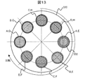
- FIG. 4A and FIG. 4B show an example of the filter 113 of the present embodiment.
- the filter 113 of this embodiment includes a plurality of types of metal foils 310 that selectively transmit X-rays in a plurality of energy bands from multicolor X-rays emitted from the X-ray source 112, and a plurality of types of metal foils 310.
- a holding unit 320 arranged and held in a plane.
- the holding part 320 is composed of two disks 321 and 322 having the same central axis, and is rotatably held around the central axis. Note that the shape of the holding portion 320 and the number of plates constituting the holding portion 320 are not limited thereto.
- Each metal foil 310 has a circular shape having a diameter larger than the diameter of the irradiation field 330.
- the metal foils 310 are arranged on the discs 321 and 322 of the holding unit 320 on the concentric circles of the discs 321 and 322 and arranged at equal intervals in the circumferential direction.
- the distance between the center of the metal foil 310 and the centers of the disks 321 and 322 is determined to be a position including the irradiation field 330 when the metal foil 310 is disposed on the X-ray passing position.
- the diameter of each metal foil 310 is set to a size that does not overlap with the adjacent metal foil 310 when arranged on the disks 321 and 322.
- Each metal foil 310 is formed of a different metal.
- aluminum Al, copper Cu, titanium Ti, iron Fe, manganese Mn, nickel Ni, silver Ag, tin Sn, zinc Zn, gadolinium Gd, or the like is used.
- 4A and 4B exemplify a case where each of the disks 321 and 322 holds four types of metal foils 310 (A, B, C, D and E, F, G, and H). To do.
- the number of metal foils 310 to be held is not limited to this.
- the switch 114 moves the holding unit 320 to arrange the plurality of types of metal foils 310 on the holding unit 320 in order at the X-ray passage positions.
- the disks 321 and 322 of the holding unit 320 are rotated around the central axis to switch the metal foil 310 disposed at the position of the irradiation field.
- the switching is performed in synchronization with the frame rate in accordance with an instruction from the arithmetic device 130.
- the disks 321 and 322 are rotated in the same direction, but the rotation direction is not limited to this.
- the polychromatic X-rays irradiated from the X-ray source 112 pass through two different metal foils 310, that is, the metal foil 311 on the disk 321 and the metal foil 312 on the disk 322, and the energy band.
- the narrow X-rays are applied to the subject 150.
- Each metal foil 310 selectively transmits X-rays in different energy bands from multicolor X-rays irradiated from the X-ray source 112.
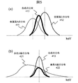
- the polychromatic X-rays irradiated by passing through the metal foil 310 show a distribution having a peak at the peak position of the monochromatic X-ray that is the characteristic X-ray of the metal.
- the distribution of X-rays transmitted through the metal foil A is 411
- the distribution of X-rays transmitted through the metal foil E distributed of the metal foil E. Is 412.
- the X-ray distribution (synthetic distribution) 413 passing through the filter 113 in which the two metal foils A and E are laminated is obtained by multiplying the distribution 411 of the metal foil A and the distribution 412 of the metal foil E. It will be a thing. As shown in this figure, the composite distribution 413 has an energy bandwidth that overlaps the distribution 411 of the metal foil A and the distribution 412 of the metal foil E, and the distribution 411 of the metal foil A and the distribution 412 of the metal foil E. This further narrows the energy bandwidth.
- the distribution of the multicolor X-rays emitted from the X-ray source 112 is 421, the multicolor X-rays pass through the filter 113 as shown in FIG. X-rays having a distributed distribution 422 are obtained.
- This distribution 422 has a narrow energy band that is equivalent to the combined distribution 413.
- the multicolor X-rays having the multicolor X-ray distribution 421 by transmitting the irradiated X-rays having the multicolor X-ray distribution 421 through the plurality of different metal foils 310, a monochromatic X-ray that is an X-ray having a narrow energy distribution can be obtained. That is, the multicolor X-rays can be monochromatic by transmitting a plurality of types of metal foils 310.
- the switcher 114 sequentially arranges the metal foils 310 on the holding units (discs 321 and 322) at the X-ray passage positions in accordance with instructions from the arithmetic device 130. At this time, switching is performed in synchronization with the frame rate of the fluoroscopic image generated by the X-ray fluoroscopic apparatus 101. At this time, various combinations can be obtained by controlling the rotation speed of each of the disks 321, 322, that is, the central angle of rotation per frame.
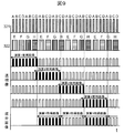
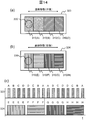
- the horizontal axis is time t.
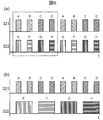
- both the disks 321 and 322 are switched to the adjacent metal foil 310 for each frame.
- the switch 114 operates the two disks 321 and 322 so that the metal foil A of the disk 321 and the metal foil E of the disk 322 overlap in the irradiation field 330. Thereafter, both disks 321 and 322 are rotated 45 degrees for each frame. As a result, the metal foils B and F, C and G, and D and H overlap in sequence at the position including the irradiation field 330 for each frame. Repeat this.
- the disk 321 is rotated at twice the speed of the disk 322 (the metal foil 310 has twice the frequency).
- the disk 321 is rotated 45 degrees for each frame
- the disk 322 is an example of a combination of the metal foils 310 when rotated 45 degrees for every two frames.
- the disk 321 is switched to the adjacent metal foil 310 every frame
- the disk 322 is switched to the adjacent metal foil 310 every two frames.
- the switch 114 operates the two disks 321 and 322 so that the metal foil A of the disk 321 and the metal foil E of the disk 322 overlap in the irradiation field 330. Thereafter, the disk 321 is rotated 45 degrees for each frame, and the disk 322 is rotated 45 degrees for each two frames.
- the metal foils B and E, C and F, D and F, A and G, B and G, C and H, and D and H are overlapped at a position including the irradiation field 330 in order for each frame.
- a combination of 8 types of metal foils can be obtained, thereby realizing 8 types of energy distribution (composite distribution).
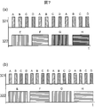
- the disk 321 is rotated at a speed three times that of the disk 322 (the metal foil 310 is three times as frequent).
- the disk 321 is rotated 45 degrees for each frame
- the disk 322 is an example of a combination of the metal foils 310 when rotated 45 degrees for every three frames.
- the disk 321 is switched to the adjacent metal foil 310 every frame
- the disk 322 is switched to the adjacent metal foil 310 every three frames.
- the switch 114 operates the two disks 321 and 322 so that the metal foil A of the disk 321 and the metal foil E of the disk 322 overlap in the irradiation field 330. Thereafter, the disk 321 is rotated 45 degrees for each frame, and the disk 322 is rotated 45 degrees for each three frames.
- the metal foils B and E, C and E, D and F, A and F, B and F, C and G, D and G, A and G, B and H, and C in order.
- H, D, and H overlap at a position including the irradiation field 330.
- 12 types of metal foils is obtained, and thereby 12 types of energy distribution (composite distribution) (monochromatic light of 12 types of energy) can be realized.
- the disk 321 is rotated at a speed four times that of the disk 322 (switched at a frequency four times). That is, the example of the combination of the metal foil 310 in the case where the disk 321 is rotated 45 degrees for each frame and the disk 322 is rotated 45 degrees for every four frames is shown. In this case, the disk 321 is switched to the adjacent metal foil 310 every frame, and the disk 322 is switched to the adjacent metal foil 310 every four frames.
- the switch 114 operates the two disks 321 and 322 so that the metal foil A of the disk 321 and the metal foil E of the disk 322 overlap in the irradiation field 330. Thereafter, the disk 321 is rotated 45 degrees for each frame, and the disk 322 is rotated 45 degrees for each four frames.
- combinations of 16 types of metal foils are obtained, and thereby 16 types of energy distribution (composite distribution; monochromatic light of 16 types of energy) can be realized.
- the arithmetic device 130 of the present embodiment controls the operations of the X-ray generator 110 and the X-ray detector 120 to convert an X-ray image of the subject 150 from the X-rays detected by the X-ray detector 120 to a predetermined frame rate.
- the acquired X-ray images are sequentially output to a display device and displayed as a moving image.
- the X-ray image displayed on the display device is a fluoroscopic image and a component image described later.
- the arithmetic device 130 controls the X-ray generator 110 so that X-rays with different energy bands are irradiated for each frame, and performs multi-energy imaging. Then, information about the elemental composition of the subject 150, that is, a component image of each element constituting the subject 150 is obtained from the obtained perspective image. Then, the obtained fluoroscopic image and component image are displayed in real time at a predetermined frame rate.
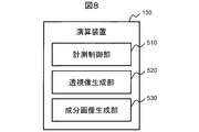
- the arithmetic device 130 of this embodiment includes a measurement control unit 510, a perspective image generation unit 520, and a component image generation unit 530, as shown in FIG.
- the computing device 130 of this embodiment includes a CPU, a memory, and a storage device.
- Each function realized by the arithmetic device 130 is realized by the CPU loading a program stored in the storage device into the memory and executing the program. All or some of the functions may be realized by hardware such as ASIC (Application Specific Integrated Circuit) or FPGA (Field-programmable gate array).
- ASIC Application Specific Integrated Circuit
- FPGA Field-programmable gate array
- the measurement control unit 510 controls the operation of the X-ray generator 110 to switch and irradiate X-rays in a plurality of energy bands in order for each of one or more predetermined number of frames. Then, the X-ray transmitted through the subject 150 is detected by the X-ray detection device 120 and output as an electric signal (measurement image). Then, the fluoroscopic image generation unit 520 and the component image generation unit 530 generate and display a fluoroscopic image and a component image in synchronization with the frame rate.
- the measurement control unit 510 when the measurement control unit 510 receives an instruction to start X-ray fluoroscopy from the user, the measurement control unit 510 pulses polychromatic X-rays with a preset tube voltage from the X-ray source 112 until an end instruction is received.
- the X-ray generator 110 is controlled to irradiate.
- the pulsed X-ray is irradiated in synchronization with a predetermined frame rate.
- the X-ray detection device 120 detects X-rays in synchronization with the pulsed X-ray irradiation.
- the measurement control unit 510 of the present embodiment instructs the switch 114 as described above, and sequentially switches the X-ray energy band irradiated in synchronization with the frame rate for each of one or more frames.
- the perspective image generation unit 520 generates a perspective image from the measurement image output from the X-ray detection device 120.
- sensitivity measurement is performed on the measurement image obtained for each frame to obtain a fluoroscopic image.
- the obtained fluoroscopic images are sequentially output and displayed on the display device 131 in synchronization with a predetermined frame rate in accordance with an instruction from the measurement control unit 510.
- the obtained fluoroscopic image is also a fluoroscopic image obtained by irradiation with X-rays having different energy bands.
- the component image generation unit 530 generates a component image for each element constituting the subject using the perspective images obtained in each of a plurality of frames, and sequentially outputs the component image to the display device 131 to display it as a moving image.
- the filter 113 is switched for each frame, and X-rays having different energy are emitted from the X-ray generator 110. Therefore, the component image generation unit 530 of the present embodiment generates a component image using the perspective images obtained by X-ray irradiation with different energy bands obtained in a plurality of frames.
- X-rays of three or more different energy bands are irradiated from the X-ray generator 110.
- the component image generation unit 530 of the present embodiment generates component images for two or more elements using the perspective images respectively obtained by X-rays of three or more energy bands.
- the component image is obtained by performing multi-energy calculation on a plurality of fluoroscopic images obtained by X-rays in different energy bands.
- the measurement control unit 510 instructs the switch 114 to switch the energy band irradiated from the X-ray generation device 110 for each frame, and the component image generation unit 530 determines the generated component image in advance.
- the images are sequentially output to the display device 131 at a frame rate and displayed as a moving image.
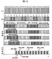
- the switch 114 receives an instruction from the measurement control unit 510 and, as shown in FIG. 9, the metal plate 310 is changed every two frames so that the type of the metal foil 310 is changed every frame 321. Each type is controlled so as to change the type. Thereby, X-rays of eight different energy bands are obtained as described above.
- the fluoroscopic image generation unit 520 sequentially generates X-ray fluoroscopic images of eight different energy bands for each frame.
- the measurement control unit 510 causes the component image generation unit 530 to calculate component images using these and sequentially displays them on the display device 131 for each frame.
- the component image is displayed over 7 frames from the next frame from which the eight perspective images are acquired.
- the component image generation unit 530 uses the perspective image of the last frame used for the previous multiframe calculation for the current multiframe calculation.
- the perspective image of the last frame used in the first multiframe calculation (calculation 1) is used as the first frame perspective image.
- the fluoroscopic images for eight frames from this fluoroscopic image have different energy bands of the irradiated X-rays, and therefore, multi-energy calculation is possible.
- the measurement control unit 510 acquires a perspective image for 8 frames only at the first (calculation 1) and then performs multi-energy calculation to obtain a component image for 7 frames.
- the component image generation unit 530 is controlled. After that, every time a perspective image for 7 frames is acquired, the component image generation unit 530 is controlled so as to obtain a component image by performing multi-energy calculation using the perspective images of the immediately preceding 8 frames.
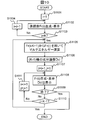
- i and j are integer counters of 1 or more.
- K is an integer of 1 or more.
- the measurement control unit 510 controls the X-ray generation device 110 and the X-ray detection device 120 to cause the fluoroscopic image generation unit 520 to generate a fluoroscopic image for each frame and display it on the display device 131 (step S1102).
- the measurement control unit 510 repeats the generation of the fluoroscopic image K times (steps S1103 and S1104).
- the fluoroscopic image generated in the i-th frame is represented as Fr (i).
- the measurement control unit 510 instructs the switch 114 to irradiate X-rays of different energy bands for each frame.
- the measurement control unit 510 causes the component image generation unit 530 to perform multi-energy calculation using the previous K fluoroscopic images (Fr (i ⁇ K + 1) to Fr (i)).
- (K-1) types of component images are generated (step S1106).
- the generated component images are represented as DcI (j) in a predetermined order.
- the measurement control unit 510 increments the counter i by 1 and initializes a counter j that counts component images (step S1107).
- the measurement control unit 510 generates and displays the perspective image Fr (i) from the next frame, and displays the generated component image DcI (j) (step S1108).
- the component image DcI (j) is displayed for each frame in a predetermined order.
- step S1110 and S1111 The acquisition of the fluoroscopic image Fr (i) and the display of the component image DcI (j) are repeated until all types (K-1) of component images are displayed. Then, when displaying all types of component images, measurement control unit 510 returns to step S1105 and repeats the process.
- the measurement control unit 510 ends the process.
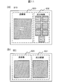
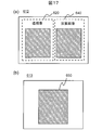
- FIG. 11A is an example of the display screen 610.
- the display screen 610 includes a perspective image display area 620 and a component image display area 630.
- the latest perspective image Fr (i) is displayed and updated for each frame.
- the component image display area 630 includes display areas for the number of types of component images created by multi-energy imaging, and is displayed and updated each time a component image of that type is generated.
- each display area of the component image display area 630 is updated every 7 frames.
- the display screen is not limited to the above configuration.
- the component image display area 631 may also be configured to include only one display area.
- component images from DcI (1) to DcI (7) are sequentially displayed and updated for each frame.
- the X-ray fluoroscopic apparatus 100 of the present embodiment includes the X-ray generation device 110 that irradiates the subject 150 with X-rays, and the X-ray detection device 120 that detects X-rays transmitted through the subject 150.
- an X-ray image of the subject 150 is acquired from the X-rays detected by the X-ray detection device 120 at a predetermined frame rate
- An arithmetic device 130 that sequentially outputs the X-ray image to the display device 131 and displays it as a moving image, and the X-ray generator 110 can independently irradiate X-rays in a plurality of energy bands
- the arithmetic unit 130 switches the X-rays of the plurality of energy bands from the X-ray generation device 110 in order for one or more predetermined number of frames to be irradiated in order.
- a component image generation unit 530 that generates a component image for each element constituting the subject using the control unit 510 and X-ray images obtained in each of a plurality of frames, and sequentially outputs the generated component image to the display device to display it as a moving image. And comprising.
- the X-ray generator 110 emits X-rays in an energy band including the plurality of energy bands, and X-rays in the plurality of energy bands from the X-rays emitted from the X-ray source 112.
- a filter 113 including a plurality of types of metal foils 310 that selectively transmit light, and a switch 114 that sequentially arranges the plurality of types of metal foils 310 at the X-ray passage positions may be provided.
- the filter 113 includes a holding unit 320 that holds the plurality of types of metal foils 310 in a plane, and the switch 114 moves the holding unit 320 to move the plurality of types of metal foils 310 to the You may arrange in order in the passage position of X-rays.
- the holding unit 320 is a disk that holds the metal foils 310 side by side in the circumferential direction, and the switch 114 rotates the disk to hold the plurality of types of metal foils 310 to the X. You may arrange in order at the passage position of a line.
- the holding unit 320 includes two or more disks, and the metal foils 310 held by the two or more disks are different in type, and the two or more disks pass the X-rays.
- the switches 114 may be arranged at respective positions, and the switch 114 may rotate the two or more disks independently of each other.
- the energy band irradiated from the X-ray generation device 110 is 3 or more, and the component image generation unit 530 uses the X-ray images respectively obtained by the X-rays of the 3 or more energy bands and uses 2 or more.
- the component image may be generated for each element.
- the measurement control unit 510 switches the energy band irradiated from the X-ray generation device 110 for each frame, and the component image generation unit 530 displays the generated component image at the frame rate at the display device 131. May be sequentially output and displayed as a moving image.
- X-ray fluoroscopic apparatus 100 X-rays having a narrow energy width are switched at high speed with different energies and irradiated to the subject 150, so that minute density changes can be identified. (Component image) is obtained.
- a plurality of disks each having a plurality of different types of metal foils 310 are installed between the X-ray source 112 and the subject 150.
- the disc is arranged so that the X-rays pass through the plurality of metal foils.
- X-rays are irradiated while rotating the disk, and a plurality of X-ray images (perspective images) are acquired by a combination of different metal foils 310.
- the obtained perspective image is subjected to multi-energy processing, and the obtained component image is displayed on the display device in real time.
- the X-ray fluoroscopic apparatus 100 of the present embodiment can irradiate X-rays in a plurality of different energy bands for each frame by rotating the filter 113 in synchronization with the frame rate. According to this embodiment, it is possible to obtain X-rays having a number of different energy peaks with a simple configuration as compared with the method of changing the tube voltage, only by switching the metal foil at the position where the X-rays pass. .
- the irradiated X-rays pass through two different metal foils 310, have an energy distribution in a narrower band than the energy band of the X-rays that have passed through only one of the metal foils 310, and more monochromatic light. It will be close to. From an image obtained using such X-rays of energy distribution, the composition components can be discriminated with higher accuracy. Therefore, according to this embodiment, a good component image can be obtained.
- the energy band of irradiated X-rays can be switched at high speed. Therefore, according to the present embodiment, the energy band can be changed for each frame, and a fluoroscopic image with X-rays having different energy bands for each frame can be obtained.
- the component image can be displayed almost in real time together with the perspective image for each frame. Therefore, a display useful for medical diagnosis can be obtained.
- a fluoroscopic image and a component image can be obtained in a moving image in real time, such as during surgery.
- a display useful for medical diagnosis can be obtained with a simple configuration and high accuracy.
- the metal foil 310 is formed in a circular shape.
- the circular metal foil 310 is advantageous in that it is easy to manufacture.
- the configuration of the filter 113 is not limited to the configuration described in the above embodiment.
- the metal foil 310 disposed on the holding unit 320 may be rectangular.
- the rectangular metal foil 310 is easy to manufacture. Moreover, it is suitable when the irradiation field 330 is narrowed down to a rectangle with a collimator or the like. The irradiation field 330 can be set wider when the rectangular metal foil 310 is used than when the circular metal foil 310 is used.
- the filter 113 has a configuration in which the metal foil 310 is attached to a fan-shaped region in which the central angles of the disks 321 and 322 of the holding unit 320 are equally divided. Also good.
- the irradiation field 330 can be arranged at a position close to the rotation center. For this reason, the diameters of the disks 321 and 322 can be reduced. As a result, the rotation of the disks 321 and 322 is stabilized and high-speed rotation can be performed. Further, there are few regions on the disks 321 and 322 where the metal foil 310 is not attached. For this reason, the discs 321 and 322 can be continuously rotated to switch the combination of the metal foil 310 by the two discs 321 and 322 for each frame.
- the shape and arrangement of the metal foil 310 on each of the disks 321 and 322 are not limited to this. Any arrangement that can be switched to a combination of different types of metal foils 310 by rotating the disks 321 and 322 may be used.
- the filter 113 creates a metal foil in which two different types of metal foils are laminated in advance, and this is formed on a single circular holding portion 320 in a circumferential direction on a concentric circle. May be arranged at equal intervals.
- the diameters of the two types of metal foils to be laminated are shown as different, but the diameters of the metal foils to be laminated are the same. May be.
- the holding unit 320 may be two rectangular plates 323 and 324.
- a plurality of different metal foils 310 are also rectangular with the same size.
- Each metal foil 310 is arrange
- the switch 114 moves the plates 323 and 324 back and forth linearly in the longitudinal direction. Thereby, the metal foil 310 at the position of the irradiation field 330 is switched.
- FIG. 14C shows an example of combination of the metal foil 310 in this case. This figure illustrates the case where the plate 323 is switched to the adjacent metal foil 310 every frame, and the plate 324 is switched to the adjacent metal foil 310 every four frames.
- This form is simple in structure and movement control.
- a moving direction is reversed. For this reason, the speed of movement decelerates and accelerates at the timing when these metal foils 310 are arranged. Therefore, the widths of the metal foils A, D, E, and H can be made shorter than those of the metal foils B, C, F, and G.
- the filter 113 may be configured to have a region that is larger than the irradiation field 330 and that is not provided with the metal foil 310 and that can transmit multicolor X-rays.
- the filter 113 may be detachable. With this configuration, it is possible to irradiate multicolor X-rays.
- (K ⁇ 1) component images obtained from X-ray fluoroscopic images of K different energy bands are displayed.
- the obtained (K-1) component images may be added to obtain one added image. Since the elements are discriminated in each component image, by superimposing these elements, it is possible to discriminate from soft tissue to hard tissue and to obtain an image with enhanced contrast.
- the measurement control unit 510 switches the energy band irradiated from the X-ray generation device 110 for each frame, and the component image generation unit 530 adds the generated component images to obtain an addition image, which is predetermined.
- the added image is displayed as a moving image on the display device 131 at the frame rate.
- the switch 114 receives an instruction from the measurement control unit 510 and, as shown in FIG. 15, the disk 322 is changed every two frames so that the type of the metal foil 310 is changed every frame 321. Each type is controlled so as to change the type. Thereby, X-rays of eight different energy bands are obtained as described above.
- the fluoroscopic image generation unit 520 sequentially generates X-ray fluoroscopic images of eight different energy bands for each frame.
- the measurement control unit 510 causes the component image generation unit 530 to calculate one added image using these.
- the addition image is obtained by calculating seven component images from eight different perspective images and adding these seven component images. Then, the calculated added image is displayed on the display device 131 in synchronization with the frame rate.
- the display of the added image is 8 frames. Only one copy per card is updated.
- the perspective images for seven frames from the second frame to the eighth frame used for the previous multiframe calculation are also used for the current multiframe calculation.
- the first multi-frame calculation uses the perspective images from the first frame to the eighth frame
- the second multi-frame calculation uses the second frame.
- To 9th frame are used.
- the perspective image of the last frame used in the first multiframe computation (calculation 1) is used as the perspective image of the first frame.
- these eight frames of the fluoroscopic images all have different energy bands of irradiation X-rays, so that multi-energy calculation is possible.
- the measurement control unit 510 of the present embodiment performs a multi-energy calculation after obtaining a perspective image for 8 frames only for the first calculation (calculation 1), and obtains an addition image for one frame.
- the component image generation unit 530 is controlled to obtain. Then, each time a fluoroscopic image for one frame is acquired, the component image generation unit 530 is controlled so as to obtain a summed image by performing multi-energy calculation using the fluoroscopic image of the eight frames acquired immediately before.
- i is an integer counter of 1 or more.
- K is an integer of 1 or more.
- the measurement control unit 510 controls the X-ray generation device 110 and the X-ray detection device 120 to cause the fluoroscopic image generation unit 520 to generate a fluoroscopic image for each frame and display it on the display device 131 (step S1202).
- the measurement control unit 510 repeats the generation of the fluoroscopic image K times (steps S1203 and S1204).
- the fluoroscopic image generated in the i-th frame is represented as Fr (i).
- the measurement control unit 510 instructs the switch 114 to irradiate X-rays of different energy bands for each frame.
- the measurement control unit 510 uses the immediately preceding K fluoroscopic images (Fr (i ⁇ K + 1) to Fr (i)) for the component image generation unit 530. Multi-energy calculation is performed (step S1205), and (K-1) types of component images DcI are generated (step S1206). Further, the component image generation unit 530 adds (K-1) types of component images DcI to generate an added image ADcI (step S1207).
- the measurement control unit 510 increments the counter i by 1 (step S1208).
- the measurement control unit 510 generates and displays the perspective image Fr (i) from the next frame, and displays the generated added image ADcI (step S1209).
- the measurement control unit 510 returns to step S1205 and repeats the process until an end instruction is received from the user (step S1210). When an end instruction is received, the process ends.
- FIG. 17A is an example of the display screen 612.
- the display screen 612 includes a perspective image display area 620 and an added image display area 640.
- the latest perspective image Fr (i) is displayed and updated for each frame.
- the added image display area 640 the latest added image ADcI is displayed and updated for each frame.
- the obtained perspective image and the added image may be added for each frame, and the added image may be displayed.
- An example of the display screen 613 in this case is shown in FIG. In this case, the latest image after addition is displayed and updated in one image display area 650 for each frame.
- phase contrast imaging using monochromatic X-rays is possible. Thereby, soft tissue identification and element discrimination are possible.
- the filter 113 can be applied to other types of imaging such as fluoroscopy, imaging, CT imaging, cone beam CT imaging, tomosynthesis imaging, and the like. Furthermore, this embodiment is not limited to the measurement by X-rays. Even measurement of light, X-rays, radiation, etc. is applicable.
Landscapes
- Health & Medical Sciences (AREA)
- Life Sciences & Earth Sciences (AREA)
- Medical Informatics (AREA)
- Engineering & Computer Science (AREA)
- Radiology & Medical Imaging (AREA)
- Biomedical Technology (AREA)
- Biophysics (AREA)
- Nuclear Medicine, Radiotherapy & Molecular Imaging (AREA)
- Optics & Photonics (AREA)
- Pathology (AREA)
- Physics & Mathematics (AREA)
- High Energy & Nuclear Physics (AREA)
- Heart & Thoracic Surgery (AREA)
- Molecular Biology (AREA)
- Surgery (AREA)
- Animal Behavior & Ethology (AREA)
- General Health & Medical Sciences (AREA)
- Public Health (AREA)
- Veterinary Medicine (AREA)
- Apparatus For Radiation Diagnosis (AREA)
Applications Claiming Priority (2)
| Application Number | Priority Date | Filing Date | Title |
|---|---|---|---|
| JP2014198921A JP2016067533A (ja) | 2014-09-29 | 2014-09-29 | X線透視撮影装置およびマルチエネルギー撮影方法 |
| JP2014-198921 | 2014-09-29 |
Publications (1)
| Publication Number | Publication Date |
|---|---|
| WO2016051996A1 true WO2016051996A1 (ja) | 2016-04-07 |
Family
ID=55630042
Family Applications (1)
| Application Number | Title | Priority Date | Filing Date |
|---|---|---|---|
| PCT/JP2015/073616 Ceased WO2016051996A1 (ja) | 2014-09-29 | 2015-08-21 | X線透視撮影装置およびマルチエネルギー撮影方法 |
Country Status (2)
| Country | Link |
|---|---|
| JP (1) | JP2016067533A (enExample) |
| WO (1) | WO2016051996A1 (enExample) |
Cited By (1)
| Publication number | Priority date | Publication date | Assignee | Title |
|---|---|---|---|---|
| US11229412B2 (en) * | 2019-10-28 | 2022-01-25 | Canon Medical Systems Corporation | X-ray imaging apparatus and monochromatic x-ray generating method |
Families Citing this family (2)
| Publication number | Priority date | Publication date | Assignee | Title |
|---|---|---|---|---|
| JP7531337B2 (ja) * | 2020-07-08 | 2024-08-09 | キヤノン株式会社 | 放射線撮影システム、制御装置、制御方法、及びプログラム |
| JP7504819B2 (ja) * | 2021-02-18 | 2024-06-24 | 富士フイルム株式会社 | 撮影制御装置、放射線画像撮影システム、撮影制御方法、及び撮影制御プログラム |
Citations (6)
| Publication number | Priority date | Publication date | Assignee | Title |
|---|---|---|---|---|
| JPH04141156A (ja) * | 1990-09-30 | 1992-05-14 | Shimadzu Corp | X線断層撮影装置 |
| JP2001087254A (ja) * | 1999-09-17 | 2001-04-03 | Hitachi Medical Corp | X線画像診断装置 |
| JP2003180669A (ja) * | 2001-12-18 | 2003-07-02 | Shimadzu Corp | X線撮影装置 |
| JP2006271437A (ja) * | 2005-03-28 | 2006-10-12 | Aloka Co Ltd | X線骨密度測定装置 |
| JP2009000293A (ja) * | 2007-06-21 | 2009-01-08 | Toshiba Corp | デュアルエネルギシステム及びその画像収集方法 |
| JP2011067333A (ja) * | 2009-09-25 | 2011-04-07 | Fujifilm Corp | 放射線画像撮影装置及び撮影制御装置 |
-
2014
- 2014-09-29 JP JP2014198921A patent/JP2016067533A/ja active Pending
-
2015
- 2015-08-21 WO PCT/JP2015/073616 patent/WO2016051996A1/ja not_active Ceased
Patent Citations (6)
| Publication number | Priority date | Publication date | Assignee | Title |
|---|---|---|---|---|
| JPH04141156A (ja) * | 1990-09-30 | 1992-05-14 | Shimadzu Corp | X線断層撮影装置 |
| JP2001087254A (ja) * | 1999-09-17 | 2001-04-03 | Hitachi Medical Corp | X線画像診断装置 |
| JP2003180669A (ja) * | 2001-12-18 | 2003-07-02 | Shimadzu Corp | X線撮影装置 |
| JP2006271437A (ja) * | 2005-03-28 | 2006-10-12 | Aloka Co Ltd | X線骨密度測定装置 |
| JP2009000293A (ja) * | 2007-06-21 | 2009-01-08 | Toshiba Corp | デュアルエネルギシステム及びその画像収集方法 |
| JP2011067333A (ja) * | 2009-09-25 | 2011-04-07 | Fujifilm Corp | 放射線画像撮影装置及び撮影制御装置 |
Cited By (1)
| Publication number | Priority date | Publication date | Assignee | Title |
|---|---|---|---|---|
| US11229412B2 (en) * | 2019-10-28 | 2022-01-25 | Canon Medical Systems Corporation | X-ray imaging apparatus and monochromatic x-ray generating method |
Also Published As
| Publication number | Publication date |
|---|---|
| JP2016067533A (ja) | 2016-05-09 |
Similar Documents
| Publication | Publication Date | Title |
|---|---|---|
| US7885372B2 (en) | System and method for energy sensitive computed tomography | |
| US4144457A (en) | Tomographic X-ray scanning system | |
| JP6636923B2 (ja) | X線画像装置 | |
| US7039153B2 (en) | Imaging tomography device with at least two beam detector systems, and method to operate such a tomography device | |
| JP3449561B2 (ja) | X線ct装置 | |
| US7463715B2 (en) | System and method for real time dual energy x-ray image acquisition | |
| JP5528518B2 (ja) | 放射線画像生成装置および方法 | |
| CN106340340B (zh) | X射线滤波 | |
| US20140270440A1 (en) | Volume image reconstruction using data from multiple energy spectra | |
| JP2020127709A (ja) | X線撮像システムの使用および較正 | |
| JP2000157525A (ja) | 浸透性放射線を利用する断層撮像法 | |
| US9360439B2 (en) | Imaging system | |
| JP2005013738A (ja) | トモシンセシス用途における対象物を走査するためのシステム及び方法 | |
| EP3517038B1 (en) | System and method to improve spatial resolution in computed tomography | |
| US8229060B2 (en) | Medical X-ray examination apparatus and method for k-edge imaging | |
| WO2013128891A1 (ja) | 画像処理装置および方法 | |
| CN120052929A (zh) | 利用x光机对拍摄区域进行双能量成像的方法和x光机 | |
| JP6346284B2 (ja) | X線ct装置、および、x線ct画像の撮影方法 | |
| WO2016051996A1 (ja) | X線透視撮影装置およびマルチエネルギー撮影方法 | |
| JP2017514632A (ja) | レーザー・コンプトンx線源を用いた二色放射線撮影の方法 | |
| US9131910B2 (en) | Method for obtaining a 3D reconstruction of an object, and X-ray device | |
| WO2015012331A1 (ja) | X線ct装置及び画像再構成方法 | |
| EP4021305B1 (en) | Multi-spectral x-ray imaging using conventional equipment | |
| WO2006003235A1 (en) | Method for producing a three-dimensional digital x-ray image | |
| KR101501101B1 (ko) | 방사선 촬영 장치, 컴퓨터 단층 촬영 장치 및 방사선 촬영 방법 |
Legal Events
| Date | Code | Title | Description |
|---|---|---|---|
| 121 | Ep: the epo has been informed by wipo that ep was designated in this application |
Ref document number: 15847989 Country of ref document: EP Kind code of ref document: A1 |
|
| NENP | Non-entry into the national phase |
Ref country code: DE |
|
| 122 | Ep: pct application non-entry in european phase |
Ref document number: 15847989 Country of ref document: EP Kind code of ref document: A1 |