WO2016051835A1 - 遠心圧縮機 - Google Patents
遠心圧縮機 Download PDFInfo
- Publication number
- WO2016051835A1 WO2016051835A1 PCT/JP2015/062095 JP2015062095W WO2016051835A1 WO 2016051835 A1 WO2016051835 A1 WO 2016051835A1 JP 2015062095 W JP2015062095 W JP 2015062095W WO 2016051835 A1 WO2016051835 A1 WO 2016051835A1
- Authority
- WO
- WIPO (PCT)
- Prior art keywords
- flow path
- centrifugal compressor
- impeller
- fluid
- axial flow
- Prior art date
Links
- 239000012530 fluid Substances 0.000 claims abstract description 67
- 238000011144 upstream manufacturing Methods 0.000 claims abstract description 21
- 230000036316 preload Effects 0.000 claims description 42
- 230000002093 peripheral effect Effects 0.000 claims description 23
- 230000005494 condensation Effects 0.000 description 38
- 238000009833 condensation Methods 0.000 description 38
- 230000006835 compression Effects 0.000 description 30
- 238000007906 compression Methods 0.000 description 30
- 238000010586 diagram Methods 0.000 description 5
- 230000014509 gene expression Effects 0.000 description 5
- 239000011555 saturated liquid Substances 0.000 description 3
- 230000003068 static effect Effects 0.000 description 3
- 239000000470 constituent Substances 0.000 description 2
- 239000007788 liquid Substances 0.000 description 2
- 238000004519 manufacturing process Methods 0.000 description 2
- 230000015556 catabolic process Effects 0.000 description 1
- 238000006731 degradation reaction Methods 0.000 description 1
- 238000006073 displacement reaction Methods 0.000 description 1
- 230000000694 effects Effects 0.000 description 1
- 239000000463 material Substances 0.000 description 1
- 238000007789 sealing Methods 0.000 description 1
- 239000000126 substance Substances 0.000 description 1
- XLYOFNOQVPJJNP-UHFFFAOYSA-N water Substances O XLYOFNOQVPJJNP-UHFFFAOYSA-N 0.000 description 1
- 238000003466 welding Methods 0.000 description 1
Images


Classifications
-
- F—MECHANICAL ENGINEERING; LIGHTING; HEATING; WEAPONS; BLASTING
- F04—POSITIVE - DISPLACEMENT MACHINES FOR LIQUIDS; PUMPS FOR LIQUIDS OR ELASTIC FLUIDS
- F04D—NON-POSITIVE-DISPLACEMENT PUMPS
- F04D19/00—Axial-flow pumps
-
- F—MECHANICAL ENGINEERING; LIGHTING; HEATING; WEAPONS; BLASTING
- F04—POSITIVE - DISPLACEMENT MACHINES FOR LIQUIDS; PUMPS FOR LIQUIDS OR ELASTIC FLUIDS
- F04D—NON-POSITIVE-DISPLACEMENT PUMPS
- F04D29/00—Details, component parts, or accessories
- F04D29/40—Casings; Connections of working fluid
- F04D29/42—Casings; Connections of working fluid for radial or helico-centrifugal pumps
- F04D29/44—Fluid-guiding means, e.g. diffusers
- F04D29/441—Fluid-guiding means, e.g. diffusers especially adapted for elastic fluid pumps
- F04D29/442—Fluid-guiding means, e.g. diffusers especially adapted for elastic fluid pumps rotating diffusers
-
- F—MECHANICAL ENGINEERING; LIGHTING; HEATING; WEAPONS; BLASTING
- F04—POSITIVE - DISPLACEMENT MACHINES FOR LIQUIDS; PUMPS FOR LIQUIDS OR ELASTIC FLUIDS
- F04D—NON-POSITIVE-DISPLACEMENT PUMPS
- F04D17/00—Radial-flow pumps, e.g. centrifugal pumps; Helico-centrifugal pumps
- F04D17/02—Radial-flow pumps, e.g. centrifugal pumps; Helico-centrifugal pumps having non-centrifugal stages, e.g. centripetal
- F04D17/025—Radial-flow pumps, e.g. centrifugal pumps; Helico-centrifugal pumps having non-centrifugal stages, e.g. centripetal comprising axial flow and radial flow stages
-
- F—MECHANICAL ENGINEERING; LIGHTING; HEATING; WEAPONS; BLASTING
- F04—POSITIVE - DISPLACEMENT MACHINES FOR LIQUIDS; PUMPS FOR LIQUIDS OR ELASTIC FLUIDS
- F04D—NON-POSITIVE-DISPLACEMENT PUMPS
- F04D17/00—Radial-flow pumps, e.g. centrifugal pumps; Helico-centrifugal pumps
- F04D17/08—Centrifugal pumps
- F04D17/10—Centrifugal pumps for compressing or evacuating
- F04D17/12—Multi-stage pumps
- F04D17/122—Multi-stage pumps the individual rotor discs being, one for each stage, on a common shaft and axially spaced, e.g. conventional centrifugal multi- stage compressors
-
- F—MECHANICAL ENGINEERING; LIGHTING; HEATING; WEAPONS; BLASTING
- F04—POSITIVE - DISPLACEMENT MACHINES FOR LIQUIDS; PUMPS FOR LIQUIDS OR ELASTIC FLUIDS
- F04D—NON-POSITIVE-DISPLACEMENT PUMPS
- F04D25/00—Pumping installations or systems
- F04D25/16—Combinations of two or more pumps ; Producing two or more separate gas flows
-
- F—MECHANICAL ENGINEERING; LIGHTING; HEATING; WEAPONS; BLASTING
- F04—POSITIVE - DISPLACEMENT MACHINES FOR LIQUIDS; PUMPS FOR LIQUIDS OR ELASTIC FLUIDS
- F04D—NON-POSITIVE-DISPLACEMENT PUMPS
- F04D29/00—Details, component parts, or accessories
- F04D29/05—Shafts or bearings, or assemblies thereof, specially adapted for elastic fluid pumps
- F04D29/053—Shafts
-
- F—MECHANICAL ENGINEERING; LIGHTING; HEATING; WEAPONS; BLASTING
- F04—POSITIVE - DISPLACEMENT MACHINES FOR LIQUIDS; PUMPS FOR LIQUIDS OR ELASTIC FLUIDS
- F04D—NON-POSITIVE-DISPLACEMENT PUMPS
- F04D29/00—Details, component parts, or accessories
- F04D29/26—Rotors specially for elastic fluids
- F04D29/28—Rotors specially for elastic fluids for centrifugal or helico-centrifugal pumps for radial-flow or helico-centrifugal pumps
- F04D29/284—Rotors specially for elastic fluids for centrifugal or helico-centrifugal pumps for radial-flow or helico-centrifugal pumps for compressors
- F04D29/286—Rotors specially for elastic fluids for centrifugal or helico-centrifugal pumps for radial-flow or helico-centrifugal pumps for compressors multi-stage rotors
-
- F—MECHANICAL ENGINEERING; LIGHTING; HEATING; WEAPONS; BLASTING
- F04—POSITIVE - DISPLACEMENT MACHINES FOR LIQUIDS; PUMPS FOR LIQUIDS OR ELASTIC FLUIDS
- F04D—NON-POSITIVE-DISPLACEMENT PUMPS
- F04D29/00—Details, component parts, or accessories
- F04D29/40—Casings; Connections of working fluid
- F04D29/42—Casings; Connections of working fluid for radial or helico-centrifugal pumps
- F04D29/4206—Casings; Connections of working fluid for radial or helico-centrifugal pumps especially adapted for elastic fluid pumps
-
- F—MECHANICAL ENGINEERING; LIGHTING; HEATING; WEAPONS; BLASTING
- F04—POSITIVE - DISPLACEMENT MACHINES FOR LIQUIDS; PUMPS FOR LIQUIDS OR ELASTIC FLUIDS
- F04D—NON-POSITIVE-DISPLACEMENT PUMPS
- F04D29/00—Details, component parts, or accessories
- F04D29/40—Casings; Connections of working fluid
- F04D29/42—Casings; Connections of working fluid for radial or helico-centrifugal pumps
- F04D29/44—Fluid-guiding means, e.g. diffusers
- F04D29/441—Fluid-guiding means, e.g. diffusers especially adapted for elastic fluid pumps
- F04D29/444—Bladed diffusers
-
- F—MECHANICAL ENGINEERING; LIGHTING; HEATING; WEAPONS; BLASTING
- F04—POSITIVE - DISPLACEMENT MACHINES FOR LIQUIDS; PUMPS FOR LIQUIDS OR ELASTIC FLUIDS
- F04D—NON-POSITIVE-DISPLACEMENT PUMPS
- F04D29/00—Details, component parts, or accessories
- F04D29/58—Cooling; Heating; Diminishing heat transfer
- F04D29/582—Cooling; Heating; Diminishing heat transfer specially adapted for elastic fluid pumps
- F04D29/5826—Cooling at least part of the working fluid in a heat exchanger
-
- F—MECHANICAL ENGINEERING; LIGHTING; HEATING; WEAPONS; BLASTING
- F05—INDEXING SCHEMES RELATING TO ENGINES OR PUMPS IN VARIOUS SUBCLASSES OF CLASSES F01-F04
- F05D—INDEXING SCHEME FOR ASPECTS RELATING TO NON-POSITIVE-DISPLACEMENT MACHINES OR ENGINES, GAS-TURBINES OR JET-PROPULSION PLANTS
- F05D2250/00—Geometry
- F05D2250/20—Three-dimensional
- F05D2250/25—Three-dimensional helical
Definitions
- the present disclosure relates to a centrifugal compressor for compressing a fluid in a gas phase or a supercritical phase.
- centrifugal compressor that compresses a fluid mainly by a centrifugal force by rotating an impeller to flow the fluid in a radial direction.
- Centrifugal compressors are widely used in various plants such as chemical plants, gas turbine plants, and refrigerators.
- Patent Document 1 discloses a centrifugal compressor in which a plurality of impellers are arranged around a main shaft.
- Patent Document 2 discloses a gas compressor provided with a centrifugal rotor having an impeller (centrifugal blade).
- a centrifugal compressor is required to maintain a high compression efficiency. If the centrifugal compressor can maintain high efficiency and lower the fluid inlet temperature, this can greatly reduce the required power of the compressor. However, when the temperature of the fluid is lowered, a portion below the saturation pressure is locally generated inside the compressor and partial condensation occurs, which may significantly reduce the performance of the compressor. In that case, water droplets generated by condensation may spread due to centrifugal force, block the flow path, and reduce the performance of the compressor.
- At least one embodiment of the present invention aims to provide a centrifugal compressor that can suppress partial condensation inside the compressor and improve compression efficiency.
- the centrifugal compressor for compressing a gas phase or supercritical phase fluid, A rotating shaft; An axial flow path extending along the axial direction of the centrifugal compressor; A radial flow path communicating with the axial flow path and extending along a radial direction of the centrifugal compressor downstream of the axial flow path; An impeller provided at least in part in the radial flow path and configured to pressurize the fluid flowing through the radial flow path by rotating together with the rotating shaft; A preload portion provided at a position away from the front edge of the impeller upstream in the axial flow path and configured to pre-pressurize the fluid introduced to the front edge of the impeller. It is characterized by that.
- the preload portion is provided in the axial flow path upstream from the front edge of the impeller, and the fluid is preloaded by the preload portion. It becomes easy to maintain the pressure above the saturation pressure, and the occurrence of partial condensation can be suppressed. Thereby, the fall of compression performance can be suppressed and compression efficiency can be maintained high.
- partial condensation occurs in the preload portion provided in the axial flow path, even in such a case, the influence on the centrifugal compressor is smaller than when partial condensation occurs in the radial flow path.
- the centrifugal compressor is a multistage compressor having at least one section in which a plurality of impellers are provided in multiple stages along the flow direction of the fluid,
- the preload portion is provided at a position away from the front edge of the first stage impeller upstream in the axial flow path upstream of the first stage impeller of each section.
- the flow path in the vicinity of the first stage impeller has a lower pressure than the flow paths in the vicinity of the other impellers, and thus is considered to have the highest risk of partial condensation.
- a preload portion is provided in the axial flow path upstream of the first stage impeller, and the fluid is pre-compressed before flowing into the radial flow path near the front edge of the first stage impeller. It is possible to effectively suppress partial condensation in a region that is easy to do (near the leading edge of the first stage impeller).
- the preload portion is configured to rotate with the rotating shaft to pressurize the fluid.
- the preload portion includes a spiral blade provided on an outer peripheral side of the rotary shaft and extending spirally along the axial direction so as to surround the rotary shaft. According to the above-described embodiment, when the rotating shaft rotates, the preload portion (spiral blade) rotates along with this, thereby guiding the fluid to the radial flow path side while increasing the pressure in the axial flow path. As described above, when the spiral blade is used as the preload portion, the pressure of the fluid can be increased by the power of the rotating shaft, so that the device configuration can be simplified.
- the preload portion further includes a shroud provided on an outer peripheral side of the spiral blade and covering the spiral blade.
- the fluid leakage flow through the clearance between the spiral blade and the casing of the centrifugal compressor can be suppressed by the shroud provided on the outer peripheral side of the spiral blade. Therefore, the pressure of the fluid can be reliably increased by the preload portion, and the occurrence of partial condensation in the radial flow path can be further suppressed.
- a seal part provided between the outer peripheral surface of the shroud and the wall surface of the casing of the centrifugal compressor facing the outer peripheral surface is further provided.
- the impeller is formed separately from the spiral blade and the shroud. Thereby, it becomes possible to produce separately an impeller and a spiral blade with a shroud, and processing becomes easy.
- the fluid pressure can be maintained at the saturation pressure or higher even in the vicinity of the front edge of the impeller. It becomes easy and generation
- FIG. 1 is a cross-sectional view showing a schematic configuration of a centrifugal compressor in some embodiments.
- FIG. 2 is an enlarged view of a main part of the centrifugal compressor in one embodiment.
- FIG. 3 is an enlarged view of a main part of a centrifugal compressor according to another embodiment.
- the third stage (discharge side) impeller 20 of the low pressure section 4 and the third stage (discharge side) impeller 20 of the high pressure section 5 face each other back to back. It is a back-to-back (Back To Back) type compressor.
- the structure of the centrifugal compressor according to the present embodiment is not limited to this type. Since the low-pressure section 4 and the high-pressure section 5 shown in FIG. 1 have substantially the same configuration, FIGS. 2 and 3 representatively show the first stage impellers 20A and 20B of the low-pressure section 4 and their peripheral structures. In these drawings, the same parts are denoted by the same reference numerals.
- a multistage centrifugal compressor (multistage compressor) 1, 1A, 1B will be described as an example.
- the centrifugal compressors 1, 1 ⁇ / b> A, 1 ⁇ / b> B in some embodiments are configured to compress a gas phase or supercritical phase fluid,
- the low pressure section 4 and the high pressure section 5 arranged around the rotary shaft 2 and a casing 6 that supports the rotary shaft 2 so as to be rotatable about its axis.
- the rotating shaft 2 is rotatably supported by the casing 6 via a bearing 9.
- the rotating shaft 2 is configured to rotate by external power such as a motor.
- the casing 6 is formed in a columnar shape, and its outer periphery is covered with a cylindrical housing 8.
- the rotating shaft 2 is disposed in the casing 6 so as to penetrate the center of the casing 6, and a flow path 10 for a fluid to be compressed is formed on the outer peripheral side of the rotating shaft 2.
- the low-pressure section 4 and the high-pressure section 5 each include a flow path 10 and impellers (impellers) 20, 20A, 20B.
- the low pressure section 4 and the high pressure section 5 may each include a diffuser 29 provided on the downstream side of the impellers 20, 20A, 20B.
- the diffuser 29 is configured to convert kinetic energy imparted to the fluid by the impellers 20, 20A, 20B into pressure energy.
- the flow path 10 includes a suction port 11 and a discharge port 17 formed in the casing 6 and the housing 8, an axial flow path 13 formed in the casing 6, and a radial flow path 14 communicating with the axial flow path 13. , Including.
- the flow path 10 includes a suction port 11, a straight flow path 12, an axial flow path 13, a radial flow path 14, and a return flow path in order from the upstream side to the downstream side. 15, the straight flow path 16, and the discharge port 17 are arranged in a state of communicating with each other.
- the straight flow path 12 communicates with the suction port 11 and extends linearly in the radial direction of the centrifugal compressors 1, 1 ⁇ / b> A, 1 ⁇ / b> B.
- the fluid sucked from the suction port 11 flows along the radial direction from the radially outer side to the inner side of the centrifugal compressors 1, 1 ⁇ / b> A, 1 ⁇ / b> B through the straight flow path 12.
- the axial flow path 13 extends along the axial direction of the centrifugal compressors 1, 1A, 1B.
- the axial flow path 13 may be formed linearly along the axial direction of the rotary shaft 2.
- the upstream end side of the axial flow path 13 communicates with the straight flow path 12 via the corner region, and the downstream end side communicates with the radial flow path 14.
- a fluid converted from a flow inward in the radial direction in the straight flow path 12 into a flow along the axial direction flows in, and the fluid flows a predetermined distance along the axial direction. It is configured as follows.
- the radial flow path 14 communicates with the axial flow path 13 and extends along the radial direction of the centrifugal compressors 1, 1 ⁇ / b> A, 1 ⁇ / b> B on the downstream side of the axial flow path 13.
- the impellers 20, 20 ⁇ / b> A, and 20 ⁇ / b> B are disposed on the upstream side (inner circumferential side), and the diffuser 29 is disposed on the downstream side (outer circumferential side).
- the radial flow path 14 changes the direction of the fluid flowing along the axial direction in the axial flow path 13 to the flow outward in the radial direction in the upstream compression region where the impellers 20, 20 ⁇ / b> A, 20 ⁇ / b> B are disposed.
- the fluid is converted and compressed by the impellers 20, 20A, 20B.
- the return flow path 15 is formed in a substantially U-shaped cross section, the upstream end side communicates with the radial flow path 14, and the downstream end side communicates with the straight flow path 16.
- the return flow path 15 reverses the flow direction of the fluid that has passed through the impellers 20, 20A, 20B and has flowed radially outward in the radial direction flow path 14 to the inside in the radial direction, thereby allowing the fluid to flow straight.
- 16 is configured to be sent out.
- the straight flow path 16 communicates with the return flow path 15 on the upstream end side and communicates with the axial flow path 13 of the next stage on the downstream end side.
- the fluid that has passed through all the stage impellers 20, 20 ⁇ / b> A, 20 ⁇ / b> B is discharged from the discharge port 17 through the final stage straight flow path 16.
- the impellers 20, 20 ⁇ / b> A, 20 ⁇ / b> B are provided at least in one stage in the axial direction of the rotary shaft 2.
- FIG. 1 exemplarily shows a configuration in which three-stage impellers 20, 20A, and 20B including the first-stage impeller are provided.
- the impellers 20, 20 ⁇ / b> A, 20 ⁇ / b> B are arranged in plural (here, three stages) at intervals in the axial direction of the rotary shaft 2.
- each stage of the impellers 20, 20 ⁇ / b> A, 20 ⁇ / b> B of each stage are arranged at least partially in the radial flow path 14 and are configured to rotate together with the rotary shaft 2 and pressurize the fluid flowing through the radial flow path 14.
- each stage of the impellers 20, 20 ⁇ / b> A, 20 ⁇ / b> B is a disc-shaped hub 21 fixed to the outer periphery of the rotating shaft 2, and a plurality of the impellers 20, 20 ⁇ / b> A, 20 ⁇ / b> B Blades (vanes) 22.
- the compression region of the radial flow path 14 described above is constituted by a space defined by the hub 21 and the adjacent blades 22.
- the centrifugal compressor 1 ⁇ / b> A has a configuration that does not have a shroud that covers the impeller 20 ⁇ / b> A.
- the centrifugal compressor 1 ⁇ / b> B further includes a shroud 27 provided so as to cover the impeller 20 ⁇ / b> B mainly for the purpose of improving the sealing performance of the flow path 10.
- the shroud 27 is attached to the tip of each blade 22 of the impeller 20B, and is arranged so as to be concentric with the rotary shaft 2.
- the compression region of the radial flow path 14 is constituted by a space defined by the hub 21, the adjacent blades 22, and the shroud 27.
- a seal portion 28 may be provided in the gap between the shroud 27 and the casing 6 in order to prevent fluid from leaking out.
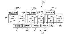
- FIG. 4 is a configuration diagram of the compression system 100 according to an embodiment.
- the compression system 100 in one embodiment includes a low-pressure compressor 101A, an intermediate-pressure compressor 101B, a high-pressure compressor 101C, and a cooler group 40 including coolers 41 to 44. At least one of the low-pressure compressor 101A, the intermediate-pressure compressor 101B, and the high-pressure compressor 101C has the same configuration as the centrifugal compressors 1, 1A, 1B described above.
- the low-pressure compressor 101A includes a first section 4A on the low-pressure side and a second section 5A on the high-pressure side.
- the intermediate pressure compressor 101B includes a third section 4B on the low pressure side and a fourth section 5B on the high pressure side.
- the high pressure compressor 101C includes a fifth section 4C on the low pressure side and a sixth section 5C on the high pressure side. That is, in comparison with the configuration example shown in FIG. 1, the first section 4A, the third section 4B, or the fifth section 4C corresponds to the low-pressure section 4, and the second section 5A, the fourth section 5B, or the sixth section 5C. Corresponds to the high pressure section 5.
- the fluid compressed in the first section 4A is cooled by the cooler 41, further compressed by the second section 5A, and sent to the cooler 42.
- the intermediate pressure compressor 101B the fluid cooled by the cooler 42 is introduced into the third section 4B, and the fluid compressed by the third section 4B is cooled by the cooler 43 and then the fourth section. It is further compressed at 5B and sent to the cooler 44.
- the high-pressure compressor 101C the fluid cooled by the cooler 44 is introduced into the fifth section 4C, compressed by the fifth section 4C, and further compressed and discharged by the sixth section 5C.
- the fluid is cooled by the cooler group 40 in order to increase the compression efficiency for the purpose of reducing power.
- the fluid compressor inlet temperature is lowered too much, a portion below the saturation pressure is locally generated inside the centrifugal compressor, and partial condensation may occur.
- FIG. 5 is a perspective view illustrating a configuration example of the impeller 20.
- the blade 22 of the impeller 20 has a front edge 23, a rear edge 24, a pressure surface 25, and a negative pressure surface 26.
- the present inventors have found that the region 50 in the vicinity of the front edge 23 of the impeller 20 (here, the blade 22), particularly the vicinity of the suction surface 26 in the front edge 23. And found that the flow rate tends to increase. From this tendency, when the centrifugal compressors 1, 1 ⁇ / b> A, 1 ⁇ / b> B are operating, the static pressure around the impeller 20 is in the vicinity of the front edge 23 of the impeller 20 (specifically, in front of the negative pressure surface 26 of the impeller 20). It was found that the risk of partial condensation was high because the static pressure in this portion was lowered.
- the centrifugal compressors 1, 1 ⁇ / b> A, 1 ⁇ / b> B according to the present embodiment further include the following configuration in order to improve compression efficiency while suppressing partial condensation inside the compressor.
- the centrifugal compressors 1, 1 ⁇ / b> A, 1 ⁇ / b> B further include preload units 30, 30 ⁇ / b> A, 30 ⁇ / b> B.
- the preload portions 30, 30 ⁇ / b> A, 30 ⁇ / b> B are provided at positions away from the front edge 23 of the impeller 20 upstream in the axial flow path 13.
- the preload unit 30 is configured to rotate around the axis together with the rotary shaft 2 to increase the pressure of the fluid flowing through the axial flow path 13. Further, the preload portion 30 is formed separately from the impeller 20.
- the preload portions 30, 30A, 30B are provided in the axial flow path 13 upstream of the front edge 23 of the impeller 20, and the preload portions 30, 30A, 30B preload the fluid. Therefore, it becomes easy to maintain the fluid pressure above the saturation pressure even in the vicinity of the front edge 23 of the impeller 20, and the occurrence of partial condensation can be suppressed. Thereby, the fall of compression performance can be suppressed and compression efficiency can be maintained high.
- partial condensation may occur in the preload sections 30, 30 ⁇ / b> A, and 30 ⁇ / b> B provided in the axial flow path 13, but even in such a case, centrifugal compression is performed more than when partial condensation occurs in the radial flow path 14.
- the influence on the machine 1, 1A, 1B is small.
- the reason is that the axial flow path 13 is different in the direction of fluid flow and the direction of centrifugal force. Therefore, even if partial condensation occurs in the axial flow path 13, the droplets are entirely formed by the centrifugal force in the axial flow path 13. Because it does not spread to.
- the liquid droplet may spread over the entire radial flow path 14 due to centrifugal force, and the flow path 10 may be blocked. is there.
- the compressor inlet temperature has been set to be considerably higher than the theoretical condensation temperature.
- the TS diagram temperature entropy diagram
- the operation line 53 for the inlet temperature has conventionally been set considerably above (on the high temperature side) the saturated liquid line 52.
- centrifugal compressors 1, 1 ⁇ / b> A, 1 ⁇ / b> B since the occurrence of partial condensation can be suppressed, for example, in the fourth section 5 ⁇ / b> B (see FIG. 4) The setting can be lowered. As a result, the power of the centrifugal compressors 1, 1A, 1B can be greatly reduced, and the compression efficiency of the centrifugal compressor can be improved.
- the fluid is pressurized by the preload portions 30, 30 ⁇ / b> A, 30 ⁇ / b> B provided in the axial flow path 13 (
- the pressure in the vicinity of the front edge 23 of the impeller 20 can be maintained at a saturation pressure or higher, and the occurrence of partial condensation can be suppressed. Therefore, it is possible to operate under operating conditions in which the inlet temperatures of the centrifugal compressors 1, 1A, 1B are lowered, that is, operating conditions in which partial condensation is likely to occur conventionally, and compression efficiency can be improved.
- the centrifugal compressors 1, 1 ⁇ / b> A, 1 ⁇ / b> B have at least one section 4, 5 in which a plurality of impellers 20, 20 ⁇ / b> A, 20 ⁇ / b> B are provided in multiple stages along the fluid flow direction. (See FIG. 1), and the preload sections 30, 30A, 30B are arranged in front of the first stage impellers 20, 20A, 20B in the axial flow path 13 upstream of the first stage impellers 20, 20A, 20B of the sections 4, 5, respectively. It is provided at a position away from the edge 23 on the upstream side.
- the flow path in the vicinity of the first stage impellers 20, 20 ⁇ / b> A, 20 ⁇ / b> B has a lower pressure than the flow path in the vicinity of other impellers. Therefore, as in the above-described embodiment, the preload portions 30, 30A, 30B are provided in the axial flow passages upstream of the first stage impellers 20, 20A, 20B, and the radius near the front edge 23 of the first stage impellers 20, 20A, 20B.
- the axial flow path 13 extends linearly along the axial direction of the centrifugal compressors 1, 1A, 1B, and is configured to have a predetermined distance.
- the distance along the axial direction of the axial flow path 13 is, for example, not less than the blade height of the front edge 23 of the impellers 20, 20A, 20B.
- the preload portions 30 ⁇ / b> A and 30 ⁇ / b> B are provided on the outer peripheral side of the rotating shaft 2 and extend spirally along the axial direction so as to surround the rotating shaft 2.
- Spiral blades 31A and 31B are included.
- the spiral blade 31A along with this, that 31B is rotated, the fluid G 1 in the axial channels 13 flows spiral blade 31A, the 31B.
- the spiral blade 31A, 31B leads radially passage 14 side while boosting the fluid G 1.
- Fluid G 2 which has passed through the spiral blade 31A, and 31B the pressure becomes higher than the fluid G 1 of the previous pass.
- the spiral blades 31A and 31B are used as the preload portions 30A and 30B, the fluid can be boosted by the power of the rotating shaft 2, and thus the device configuration can be simplified.
- the preload portions 30A and 30B have a cylindrical portion (not shown) arranged so as to surround the outer peripheral surface of the rotating shaft 2, and the spiral blades 31A and 31B are provided on the outer peripheral surface of the cylindrical portion. Also good. Thereby, the mounting property to the rotating shaft 2 of preload part 30A, 30B can be improved. Furthermore, in one configuration example, at least a part of the axial flow path 13 is defined by the spiral blades 31 ⁇ / b> A and 31 ⁇ / b> B and the casing 6.
- the casing 6 does not exist on the outer periphery of the rotary shaft 2, and the outer peripheral surface of the rotary shaft 2 is exposed to the axial flow path 13. ing.
- the preload portions 30A and 30B are attached to the outer peripheral surface of the rotating shaft 2 exposed in the axial flow path 13. With this configuration, it is easy to attach the preload portions 30A and 30B that rotate with the rotary shaft 2.
- the preload portion 30B further includes a shroud 32 that is provided on the outer peripheral side of the spiral blade 31B and covers the spiral blade 31B.
- the shroud 32 is formed in an annular shape around the axis O of the rotary shaft 2.
- the shroud 32 and the spiral blade 31B may be configured integrally.
- the shroud 32 is attached to the outer peripheral surface of the spiral blade 31 ⁇ / b> B and is configured to rotate together with the spiral blade 31 ⁇ / b> B fixed to the rotary shaft 2.
- the shroud 32 and the spiral blade 31B may be formed as separate members, and these members may be joined and integrated by welding or the like.
- the fluid flow through the clearance between the spiral blade 31B and the casing 6 of the centrifugal compressor 1B can be suppressed by the shroud 32 provided on the outer peripheral side of the spiral blade 31B. Therefore, the pressure of the fluid can be reliably increased by the preload portion 30B, and the occurrence of partial condensation in the radial flow path 14 can be further suppressed.
- the seal portion 33 is formed in an annular shape, and is disposed between the inner wall of the casing 6 that faces the shroud 32 and the outer peripheral surface (back surface) of the shroud 32.
- the seal portion 33 may be provided in the upstream region of the axial flow path 13.
- an annular groove portion (not shown) centering on the axis O of the rotating shaft 2 is provided on at least one of the outer peripheral surface of the shroud 32 or the wall surface of the casing 6, and the annular seal portion 33 is accommodated in this groove portion. May be.
- the impeller 20B may be formed as a separate body from the spiral blade 31B and the shroud 32. Thereby, it becomes possible to produce separately the impeller 20B and the spiral blade 31B with a shroud, and processing becomes easy.
- the leading edge 23 of the impellers 20, 20A, 20B since the fluid flowing into the radial flow path 14 is preloaded by the preloading portions 30, 30A, 30B, the leading edge 23 of the impellers 20, 20A, 20B. Even in the vicinity of, it becomes easy to maintain the pressure of the fluid at or above the saturation pressure, and the occurrence of partial condensation can be suppressed. Thereby, the fall of compression performance can be suppressed and compression efficiency can be maintained high. Therefore, it becomes possible to operate the centrifugal compressors 1, 1A, 1B under operating conditions in which the inlet temperature is lowered, and the compression efficiency can be further improved.
- the present invention is not limited to the above-described embodiments, and includes forms obtained by modifying the above-described embodiments and forms obtained by appropriately combining these forms.
- the multistage centrifugal compressor (multistage compressor) 1, 1A, 1B has been described as an example. However, a part of the configuration of this embodiment may be applied to a single stage compressor (1 stage compressor). Applicable.
- the said embodiment demonstrated the structure containing spiral blade 31A, 31B as the precompression part 30,30A, 30B, the precompression part 30,30A, 30B is not limited to this structure.
- the specific configuration of the preload portions 30, 30 ⁇ / b> A, 30 ⁇ / b> B is not particularly limited as long as the preload portions 30, 30 ⁇ / b> A, 30 ⁇ / b> B are arranged in the axial flow path 13 and can preload fluid.
- expressions representing shapes such as quadrangular shapes and cylindrical shapes represent not only geometrically strict shapes such as quadrangular shapes and cylindrical shapes, but also irregularities and chamfers as long as the same effects can be obtained.
- a shape including a part or the like is also expressed.
- the expression “comprising”, “including”, or “having” one constituent element is not an exclusive expression that excludes the presence of the other constituent elements.
Abstract
気相又は超臨界相の流体を圧縮するための遠心圧縮機は、回転シャフトと、前記遠心圧縮機の軸方向に沿って延在する軸方向流路と、前記軸方向流路に連通するとともに、前記軸方向流路の下流側において前記遠心圧縮機の半径方向に沿って延在する半径方向流路と、少なくとも一部が前記半径方向流路に設けられ、前記回転シャフトとともに回転して前記半径方向流路を流れる前記流体を昇圧するように構成されたインペラと、前記軸方向流路において、前記インペラの前縁から上流側に離れた位置に設けられ、前記インペラの前記前縁に導入される前記流体を予め昇圧するように構成された予圧部と、を備える。
Description
本開示は、気相又は超臨界相の流体を圧縮するための遠心圧縮機に関する。
従来、インペラを回転させて流体を径方向へ通流させることで、主として遠心力によって流体を圧縮する遠心圧縮機が知られている。遠心圧縮機は、例えば、化学プラント、ガスタービンプラント、冷凍機等の各種プラントに広く用いられている。
例えば、特許文献1には、複数のインペラが主軸の周りに配置された遠心圧縮機が開示されている。また、特許文献2には、インペラ(遠心流ブレード)を有する遠心ロータを備えたガス圧縮機が開示されている。
ところで、遠心圧縮機においては、圧縮効率を高く維持することが要求される。遠心圧縮機において高い効率を維持して流体の入口温度を下げることができれば、これにより圧縮機の必要動力を大幅に低減できる。しかし、流体の温度を下げると、圧縮機の内部において飽和圧力以下の部分が局所的に生じて部分凝縮が発生し、圧縮機の性能を著しく低下させる可能性がある。その場合、凝縮により発生した水滴は、遠心力によって広がって流路を閉塞し、圧縮機の性能を低下させることがある。
上述の事情に鑑みて、本発明の少なくとも一実施形態は、圧縮機内部における部分凝縮を抑制し、圧縮効率を向上し得る遠心圧縮機を提供することを目的とする。
本発明者らの鋭意検討の結果、遠心圧縮機の性能低下の一要因となる部分凝縮は、インペラの入口側の流路で発生し易いという知見が得られた。本発明者らは、CFDの結果、インペラの前縁近傍、特に前縁のうち負圧面近傍で、流速が高くなる傾向があることを見出した。この傾向から、遠心圧縮機が稼働している状態においてインペラ周囲の静圧は、インペラの前縁近傍(具体的には、インペラ負圧面の前縁近傍)で最も低くなっており、この部分における部分凝縮のリスクが高いことが分かった。
そこで、遠心圧縮機における圧縮効率の向上を図るためには、インペラの前縁部分における部分凝縮の発生を抑制することが重要である。
そこで、遠心圧縮機における圧縮効率の向上を図るためには、インペラの前縁部分における部分凝縮の発生を抑制することが重要である。
本発明の少なくとも一実施形態に係る遠心圧縮機は、本発明者らの上記知見に基づくものであり、
気相又は超臨界相の流体を圧縮するための遠心圧縮機が、
回転シャフトと、
前記遠心圧縮機の軸方向に沿って延在する軸方向流路と、
前記軸方向流路に連通するとともに、前記軸方向流路の下流側において前記遠心圧縮機の半径方向に沿って延在する半径方向流路と、
少なくとも一部が前記半径方向流路に設けられ、前記回転シャフトとともに回転して前記半径方向流路を流れる前記流体を昇圧するように構成されたインペラと、
前記軸方向流路において、前記インペラの前縁から上流側に離れた位置に設けられ、前記インペラの前記前縁に導入される前記流体を予め昇圧するように構成された予圧部と、を備えることを特徴とする。
気相又は超臨界相の流体を圧縮するための遠心圧縮機が、
回転シャフトと、
前記遠心圧縮機の軸方向に沿って延在する軸方向流路と、
前記軸方向流路に連通するとともに、前記軸方向流路の下流側において前記遠心圧縮機の半径方向に沿って延在する半径方向流路と、
少なくとも一部が前記半径方向流路に設けられ、前記回転シャフトとともに回転して前記半径方向流路を流れる前記流体を昇圧するように構成されたインペラと、
前記軸方向流路において、前記インペラの前縁から上流側に離れた位置に設けられ、前記インペラの前記前縁に導入される前記流体を予め昇圧するように構成された予圧部と、を備えることを特徴とする。
上記遠心圧縮機によれば、インペラの前縁よりも上流側の軸方向流路に予圧部が設けられ、この予圧部によって流体を予圧するようにしたので、インペラの前縁近傍においても流体の圧力を飽和圧力以上に維持することが容易となり、部分凝縮の発生を抑制できる。これにより、圧縮性能の低下を抑制し、圧縮効率を高く維持することができる。
なお、軸方向流路に設けられた予圧部において部分凝縮が発生することも考えられるが、そういった場合でも、半径方向流路で部分凝縮が発生する場合よりも遠心圧縮機への影響は小さい。その理由として、軸方向流路は流体の流れ方向と遠心力の方向とが異なるので、軸方向流路で部分凝縮が発生しても遠心力によって液滴が軸方向流路の全体に広がることはないからである。これに対し、半径方向流路の入口側で部分凝縮により液滴が発生した場合、遠心力によって液滴が半径方向流路の全体に広がって流路が閉塞してしまう可能性がある。
このように、遠心圧縮機の入口温度が低い場合であっても、軸方向流路に設けた予圧部で流体を昇圧(予圧)することによって、インペラ前縁近傍における圧力を飽和圧力以上に維持可能となり、部分凝縮の発生を抑制できる。よって、遠心圧縮機の入口温度を下げた運転条件(すなわち従来は部分凝縮が起こりやすかった運転条件)での運転が可能になり、圧縮効率の向上が図れる。
幾つかの実施形態において、前記遠心圧縮機は、複数の前記インペラが前記流体の流れ方向に沿って多段に設けられたセクションを少なくとも一つ有する多段圧縮機であり、
前記予圧部は、各セクションの初段インペラの上流側の前記軸方向流路において、前記初段インペラの前縁から上流側に離れた位置に設けられている。
多段圧縮機の場合、初段インペラ近傍の流路は他のインペラ近傍の流路よりも圧力が低いため、最も部分凝縮のリスクが高いと考えられる。そのため、上記実施形態のように、初段インペラの上流側の軸方向流路に予圧部を設け、初段インペラの前縁近傍の半径方向流路に流入する前に流体を予圧することによって、最も凝縮し易い領域(初段インペラの前縁近傍)での部分凝縮を効果的に抑制することができる。
前記予圧部は、各セクションの初段インペラの上流側の前記軸方向流路において、前記初段インペラの前縁から上流側に離れた位置に設けられている。
多段圧縮機の場合、初段インペラ近傍の流路は他のインペラ近傍の流路よりも圧力が低いため、最も部分凝縮のリスクが高いと考えられる。そのため、上記実施形態のように、初段インペラの上流側の軸方向流路に予圧部を設け、初段インペラの前縁近傍の半径方向流路に流入する前に流体を予圧することによって、最も凝縮し易い領域(初段インペラの前縁近傍)での部分凝縮を効果的に抑制することができる。
幾つかの実施形態において、前記予圧部は、前記回転シャフトとともに回転して前記流体を昇圧するように構成されている。一実施形態において、前記予圧部は、前記回転シャフトの外周側に設けられ、前記回転シャフトを取り巻くように前記軸方向に沿って螺旋状に延在する螺旋羽根を含む。
上記実施形態によれば、回転シャフトが回転すると、これに伴って予圧部(螺旋羽根)が回転することで、軸方向流路において流体を昇圧しながら半径方向流路側へ導く。このように、予圧部として螺旋羽根を用いれば、回転シャフトの動力によって流体を昇圧することができるので、機器構成の簡素化が図れる。
上記実施形態によれば、回転シャフトが回転すると、これに伴って予圧部(螺旋羽根)が回転することで、軸方向流路において流体を昇圧しながら半径方向流路側へ導く。このように、予圧部として螺旋羽根を用いれば、回転シャフトの動力によって流体を昇圧することができるので、機器構成の簡素化が図れる。
一実施形態において、前記予圧部は、前記螺旋羽根の外周側に設けられ、前記螺旋羽根を覆うシュラウドをさらに含む。
上記実施形態によれば、螺旋羽根の外周側に設けられたシュラウドによって、螺旋羽根と遠心圧縮機のケーシングとの間のクリアランスを介した流体の漏れ流れを抑制できる。よって、予圧部による流体の昇圧を確実に行うことができ、半径方向流路における部分凝縮の発生をより一層抑制できる。
上記実施形態によれば、螺旋羽根の外周側に設けられたシュラウドによって、螺旋羽根と遠心圧縮機のケーシングとの間のクリアランスを介した流体の漏れ流れを抑制できる。よって、予圧部による流体の昇圧を確実に行うことができ、半径方向流路における部分凝縮の発生をより一層抑制できる。
一実施形態において、前記シュラウドの外周面と、該外周面に対向する前記遠心圧縮機のケーシングの壁面との間に設けられるシール部をさらに備える。
このようにシール部を設けることによって、螺旋羽根と遠心圧縮機のケーシングとの間のクリアランスを介した流体の漏れ流れをより一層抑制できる。
このようにシール部を設けることによって、螺旋羽根と遠心圧縮機のケーシングとの間のクリアランスを介した流体の漏れ流れをより一層抑制できる。
幾つかの実施形態において、前記インペラは、前記螺旋羽根及び前記シュラウドとは別体として形成されている。
これにより、インペラと、シュラウド付き螺旋羽根とを別々に作製することが可能になり、加工が容易になる。
これにより、インペラと、シュラウド付き螺旋羽根とを別々に作製することが可能になり、加工が容易になる。
本発明の少なくとも一実施形態によれば、予圧部によって、半径方向流路に流入する流体を予圧するようにしたので、インペラの前縁近傍においても流体の圧力を飽和圧力以上に維持することが容易となり、部分凝縮の発生を抑制できる。これにより、圧縮性能の低下を抑制し、圧縮効率を高く維持することができる。よって、遠心圧縮機の入口温度を下げた運転条件での運転が可能になり、圧縮効率のさらなる向上が図れる。
以下、添付図面を参照して本発明の幾つかの実施形態について説明する。ただし、実施形態として記載されている又は図面に示されている構成部品の寸法、材質、形状、その相対的配置等は、本発明の範囲をこれに限定する趣旨ではなく、単なる説明例にすぎない。
最初に、図1乃至図3を参照して、本実施形態に係る遠心圧縮機1,1A,1Bの概略構成について説明する。ここで、図1は、幾つかの実施形態における遠心圧縮機の概略構成を示す断面図である。図2は、一実施形態における遠心圧縮機の要部拡大図である。図3は、他の実施形態における遠心圧縮機の要部拡大図である。
なお、図1に示す遠心圧縮機1は、低圧セクション4の3段目(吐出側)のインペラ20と、高圧セクション5の3段目(吐出側)のインペラ20とが、互いに背中合わせに対向して配置されたバックツーバック(Back To Back)型の圧縮機である。但し、本実施形態に係る遠心圧縮機の構造はこの型に限定されるものではない。図1に示す低圧セクション4及び高圧セクション5は概ね同一の構成を有するため、図2及び図3には代表して低圧セクション4の初段インペラ20A,20B及びその周辺構造を示している。これらの図において、同一の部位には同一の符号を付している。
以下の実施形態では、一例として多段式の遠心圧縮機(多段圧縮機)1,1A,1Bについて説明する。
図1乃至図3に示すように、幾つかの実施形態における遠心圧縮機1,1A,1Bは、気相又は超臨界相の流体を圧縮するように構成されており、主として、回転シャフト2と、回転シャフト2の周囲に配置された低圧セクション4及び高圧セクション5と、回転シャフト2を軸回りに回転可能に支持するケーシング6と、を備える。
図1乃至図3に示すように、幾つかの実施形態における遠心圧縮機1,1A,1Bは、気相又は超臨界相の流体を圧縮するように構成されており、主として、回転シャフト2と、回転シャフト2の周囲に配置された低圧セクション4及び高圧セクション5と、回転シャフト2を軸回りに回転可能に支持するケーシング6と、を備える。
回転シャフト2は、軸受9を介してケーシング6に回転可能に支持される。回転シャフト2は、モータ等の外部の動力によって回転するように構成されている。
ケーシング6は円柱状に形成され、その外周が円筒状のハウジング8で覆われている。また、ケーシング6には、該ケーシング6の中心を貫くように回転シャフト2が配置されており、回転シャフト2の外周側に、圧縮対象である流体のための流路10が形成されている。
ケーシング6は円柱状に形成され、その外周が円筒状のハウジング8で覆われている。また、ケーシング6には、該ケーシング6の中心を貫くように回転シャフト2が配置されており、回転シャフト2の外周側に、圧縮対象である流体のための流路10が形成されている。
低圧セクション4及び高圧セクション5は、それぞれ、流路10と、インペラ(羽根車)20,20A,20Bと、を備えている。なお、低圧セクション4及び高圧セクション5は、それぞれ、インペラ20,20A,20Bよりも下流側に設けられたディフューザ29を備えていてもよい。ディフューザ29は、インペラ20,20A,20Bによって流体に与えられた運動エネルギーを圧力エネルギーに変換するように構成される。
流路10は、ケーシング6及びハウジング8に形成された吸込口11及び吐出口17と、ケーシング6に形成された軸方向流路13と、軸方向流路13に連通した半径方向流路14と、を含んでいる。
具体的な構成例として、流路10は、上流側から下流側に向けて順に、吸込口11と、ストレート流路12と、軸方向流路13と、半径方向流路14と、リターン流路15と、ストレート流路16と、吐出口17と、が互いに連通した状態で配置された構成となっている。
具体的な構成例として、流路10は、上流側から下流側に向けて順に、吸込口11と、ストレート流路12と、軸方向流路13と、半径方向流路14と、リターン流路15と、ストレート流路16と、吐出口17と、が互いに連通した状態で配置された構成となっている。
ストレート流路12は、吸込口11に連通しており、遠心圧縮機1,1A,1Bの半径方向に直線状に延在している。吸込口11から吸い込まれた流体は、ストレート流路12を通って、遠心圧縮機1,1A,1Bの径方向外方から内方へ向けて径方向に沿って流れる。
軸方向流路13は、遠心圧縮機1,1A,1Bの軸方向に沿って延在している。軸方向流路13は、回転シャフト2の軸方向に沿って直線状に形成されていてもよい。軸方向流路13の上流端側はコーナー領域を介してストレート流路12に連通し、下流端側は半径方向流路14に連通している。この軸方向流路13は、ストレート流路12にて径方向内方へ向かう流れから軸方向に沿った流れに変換された流体が流入し、該流体が軸方向に沿って所定の距離を流れるように構成されている。
軸方向流路13は、遠心圧縮機1,1A,1Bの軸方向に沿って延在している。軸方向流路13は、回転シャフト2の軸方向に沿って直線状に形成されていてもよい。軸方向流路13の上流端側はコーナー領域を介してストレート流路12に連通し、下流端側は半径方向流路14に連通している。この軸方向流路13は、ストレート流路12にて径方向内方へ向かう流れから軸方向に沿った流れに変換された流体が流入し、該流体が軸方向に沿って所定の距離を流れるように構成されている。
半径方向流路14は、軸方向流路13に連通するとともに、軸方向流路13の下流側において遠心圧縮機1,1A,1Bの半径方向に沿って延在している。半径方向流路14には、上流側(内周側)にインペラ20,20A,20Bが配置され、下流側(外周側)にディフューザ29が配置されている。この半径方向流路14は、インペラ20,20A,20Bが配置された上流側の圧縮領域において、軸方向流路13にて軸方向に沿って流れる流体の方向を径方向外方へ向かう流れに変換し、インペラ20,20A,20Bによって流体を圧縮させるように構成されている。
リターン流路15は、断面略U字状に形成され、上流端側は半径方向流路14に連通しており、下流端側はストレート流路16に連通している。このリターン流路15は、インペラ20,20A,20Bを通過して半径方向流路14を径方向外方に流れてきた流体の流れ方向を径方向内方に反転させて、流体をストレート流路16に送り出すように構成されている。
ストレート流路16は、上流端側がリターン流路15に連通しており、下流端側が次段の軸方向流路13に連通している。
全段のインペラ20,20A,20Bを通過した流体は、最終段のストレート流路16を通って吐出口17より吐出される。
リターン流路15は、断面略U字状に形成され、上流端側は半径方向流路14に連通しており、下流端側はストレート流路16に連通している。このリターン流路15は、インペラ20,20A,20Bを通過して半径方向流路14を径方向外方に流れてきた流体の流れ方向を径方向内方に反転させて、流体をストレート流路16に送り出すように構成されている。
ストレート流路16は、上流端側がリターン流路15に連通しており、下流端側が次段の軸方向流路13に連通している。
全段のインペラ20,20A,20Bを通過した流体は、最終段のストレート流路16を通って吐出口17より吐出される。
インペラ20,20A,20Bは、回転シャフト2の軸方向に少なくとも一段設けられている。なお、図1では例示的に、初段インペラを含む三段のインペラ20,20A,20Bが設けられた構成を示している。この構成において、インペラ20,20A,20Bは、回転シャフト2の軸方向に間隔をあけて複数(ここでは三段)配列されている。
各段のインペラ20,20A,20Bは、少なくとも一部が半径方向流路14に配置され、回転シャフト2とともに回転して半径方向流路14を流れる流体を昇圧するように構成されている。具体的には、各段のインペラ20,20A,20Bは、回転シャフト2の外周に固定された円盤状のハブ21と、ハブ21に固定され、該ハブ21に対して放射状に配列された複数の羽根(ベーン)22と、を有している。上記した半径方向流路14の圧縮領域は、ハブ21と、隣り合う羽根22とで画成される空間によって構成される。
各段のインペラ20,20A,20Bは、少なくとも一部が半径方向流路14に配置され、回転シャフト2とともに回転して半径方向流路14を流れる流体を昇圧するように構成されている。具体的には、各段のインペラ20,20A,20Bは、回転シャフト2の外周に固定された円盤状のハブ21と、ハブ21に固定され、該ハブ21に対して放射状に配列された複数の羽根(ベーン)22と、を有している。上記した半径方向流路14の圧縮領域は、ハブ21と、隣り合う羽根22とで画成される空間によって構成される。
図2に示す実施形態において、遠心圧縮機1Aは、インペラ20Aを覆うシュラウドを有していない構成となっている。
一方、図3に示す実施形態において、遠心圧縮機1Bは、主に流路10の密閉性向上を目的として、インペラ20Bを覆うように設けられたシュラウド27をさらに備えている。シュラウド27は、インペラ20Bの各羽根22の先端に取り付けられており、回転シャフト2と同心円をなすように配置されている。この実施形態においては、半径方向流路14の圧縮領域は、ハブ21と、隣り合う羽根22と、シュラウド27とで画定される空間によって構成される。シュラウド27とケーシング6との間の隙間には、流体が漏れ出ることを防止するために、シール部28が設けられていてもよい。
一方、図3に示す実施形態において、遠心圧縮機1Bは、主に流路10の密閉性向上を目的として、インペラ20Bを覆うように設けられたシュラウド27をさらに備えている。シュラウド27は、インペラ20Bの各羽根22の先端に取り付けられており、回転シャフト2と同心円をなすように配置されている。この実施形態においては、半径方向流路14の圧縮領域は、ハブ21と、隣り合う羽根22と、シュラウド27とで画定される空間によって構成される。シュラウド27とケーシング6との間の隙間には、流体が漏れ出ることを防止するために、シール部28が設けられていてもよい。
図4は、一実施形態における圧縮システム100の構成図である。
一実施形態における圧縮システム100は、低圧圧縮機101Aと、中圧圧縮機101Bと、高圧圧縮機101Cと、冷却器41~44を含む冷却器群40と、を備えている。低圧圧縮機101A、中圧圧縮機101B及び高圧圧縮機101Cの少なくともいずれかは、上述した遠心圧縮機1,1A,1Bと同一の構成を有している。
一実施形態における圧縮システム100は、低圧圧縮機101Aと、中圧圧縮機101Bと、高圧圧縮機101Cと、冷却器41~44を含む冷却器群40と、を備えている。低圧圧縮機101A、中圧圧縮機101B及び高圧圧縮機101Cの少なくともいずれかは、上述した遠心圧縮機1,1A,1Bと同一の構成を有している。
低圧圧縮機101Aは、低圧側の第1セクション4A及び高圧側の第2セクション5Aを含んでいる。中圧圧縮機101Bは、低圧側の第3セクション4B及び高圧側の第4セクション5Bを含んでいる。高圧圧縮機101Cは、低圧側の第5セクション4C及び高圧側の第6セクション5Cを含んでいる。すなわち、図1に示す構成例と照らし合わせれば、第1セクション4A、第3セクション4B又は第5セクション4Cが低圧セクション4に相当し、第2セクション5A、第4セクション5B又は第6セクション5Cが高圧セクション5に相当する。
上記圧縮システム100では、低圧圧縮機101Aにおいて、第1セクション4Aで圧縮された流体は、冷却器41にて冷却された後、第2セクション5Aでさらに圧縮されて、冷却器42に送られる。次いで、中圧圧縮機101Bにおいて、冷却器42で冷却された流体は第3セクション4Bに導入され、第3セクション4Bで圧縮された流体は、冷却器43にて冷却された後、第4セクション5Bでさらに圧縮されて、冷却器44に送られる。さらに、高圧圧縮機101Cにおいて、冷却器44で冷却された流体は第5セクション4Cに導入され、第5セクション4Cで圧縮された後、第6セクション5Cでさらに圧縮されて排出される。
通常、圧縮システム100では、上述したように、動力削減を目的として圧縮効率を高めるために冷却器群40によって流体を冷却している。ところが、流体の圧縮機入口温度を下げ過ぎると、遠心圧縮機の内部において飽和圧力以下の部分が局所的に生じて部分凝縮が発生してしまう可能性がある。
本発明者らの鋭意検討の結果、遠心圧縮機1,1A,1Bの性能低下の一要因となる部分凝縮は、図5に示すように、インペラ20の入口側の領域50で発生し易いという知見が得られた。なお、図5は、インペラ20の構成例を示す斜視図である。具体的には、インペラ20の羽根22は、前縁23と、後縁24と、圧力面25と、負圧面26と、を有している。本発明者らは、CFD(数値流体解析:Computational Fluid Dynamics)を行った結果、インペラ20(ここでは羽根22)の前縁23の近傍、特に前縁23のうち負圧面26の近傍の領域50で、流速が高くなる傾向があることを見出した。この傾向から、遠心圧縮機1,1A,1Bが稼働している状態においてインペラ20の周囲の静圧は、インペラ20の前縁23の近傍(具体的には、インペラ20の負圧面26の前縁23の近傍)で最も低くなっており、この部分における静圧が低下することから部分凝縮のリスクが高いことが分かった。圧縮機入口温度を低く設定し、遠心圧縮機1,1A,1Bにおける圧縮効率の向上を図るためには、インペラ20の前縁部分における部分凝縮の発生を抑制することが重要である。
そこで、本実施形態に係る遠心圧縮機1,1A,1Bは、圧縮機内部における部分凝縮を抑制しながら圧縮効率を向上するために、さらに以下の構成を備えている。
図1乃至図3に示すように、幾つかの実施形態において、遠心圧縮機1,1A,1Bは、予圧部30,30A,30Bをさらに備える。
予圧部30,30A,30Bは、軸方向流路13において、インペラ20の前縁23から上流側に離れた位置に設けられる。また、予圧部30は、回転シャフト2とともに軸回りに回転して、軸方向流路13を流れる流体を昇圧するように構成されている。さらに、予圧部30は、インペラ20とは別体で形成されている。
予圧部30,30A,30Bは、軸方向流路13において、インペラ20の前縁23から上流側に離れた位置に設けられる。また、予圧部30は、回転シャフト2とともに軸回りに回転して、軸方向流路13を流れる流体を昇圧するように構成されている。さらに、予圧部30は、インペラ20とは別体で形成されている。
上記実施形態によれば、インペラ20の前縁23よりも上流側の軸方向流路13に予圧部30,30A,30Bが設けられ、この予圧部30,30A,30Bによって流体を予圧するようにしたので、インペラ20の前縁23の近傍においても流体の圧力を飽和圧力以上に維持することが容易となり、部分凝縮の発生を抑制できる。これにより、圧縮性能の低下を抑制し、圧縮効率を高く維持することができる。
なお、軸方向流路13に設けられた予圧部30,30A,30Bにおいて部分凝縮が発生することも考えられるが、そういった場合でも、半径方向流路14で部分凝縮が発生する場合よりも遠心圧縮機1,1A,1Bへの影響は小さい。その理由として、軸方向流路13は流体の流れ方向と遠心力の方向とが異なるので、軸方向流路13で部分凝縮が発生しても遠心力によって液滴が軸方向流路13の全体に広がることはないからである。これに対し、半径方向流路14の入口側で部分凝縮により液滴が発生した場合、遠心力によって液滴が半径方向流路14の全体に広がって流路10が閉塞してしまう可能性がある。
なお、軸方向流路13に設けられた予圧部30,30A,30Bにおいて部分凝縮が発生することも考えられるが、そういった場合でも、半径方向流路14で部分凝縮が発生する場合よりも遠心圧縮機1,1A,1Bへの影響は小さい。その理由として、軸方向流路13は流体の流れ方向と遠心力の方向とが異なるので、軸方向流路13で部分凝縮が発生しても遠心力によって液滴が軸方向流路13の全体に広がることはないからである。これに対し、半径方向流路14の入口側で部分凝縮により液滴が発生した場合、遠心力によって液滴が半径方向流路14の全体に広がって流路10が閉塞してしまう可能性がある。
一般的に、図4に示すような圧縮システム100では、部分凝縮が発生する懸念があることから、従来は圧縮機入口温度を理論上の凝縮温度よりもかなり高い温度に設定していた。図6のT-S線図(温度エントロピー線図)に示すように、理論上は、臨界点を含む飽和液線52よりも温度が高い領域であれば凝縮は発生しないと考えられる。しかし、部分凝縮が発生する可能性を考慮して、従来は飽和液線52よりもかなり上方(高温側)に入口温度の運転ライン53が設定されていた。
これに対して、上記実施形態に係る遠心圧縮機1,1A,1Bによれば、部分凝縮の発生を抑制できるため、例えば第4セクション5B(図4参照)では、運転ライン54まで入口温度の設定を下げることができる。これにより、遠心圧縮機1,1A,1Bの動力を大幅に低減することができ、遠心圧縮機の圧縮効率の向上が図れる。
このように、上記実施形態によれば、遠心圧縮機1,1A,1Bの入口温度が低い場合であっても、軸方向流路13に設けた予圧部30,30A,30Bで流体を昇圧(予圧)することによって、インペラ20の前縁23の近傍における圧力を飽和圧力以上に維持可能となり、部分凝縮の発生を抑制できる。よって、遠心圧縮機1,1A,1Bの入口温度を下げた運転条件、すなわち従来は部分凝縮が起こりやすかった運転条件での運転が可能になり、圧縮効率の向上が図れる。
このように、上記実施形態によれば、遠心圧縮機1,1A,1Bの入口温度が低い場合であっても、軸方向流路13に設けた予圧部30,30A,30Bで流体を昇圧(予圧)することによって、インペラ20の前縁23の近傍における圧力を飽和圧力以上に維持可能となり、部分凝縮の発生を抑制できる。よって、遠心圧縮機1,1A,1Bの入口温度を下げた運転条件、すなわち従来は部分凝縮が起こりやすかった運転条件での運転が可能になり、圧縮効率の向上が図れる。
幾つかの実施形態において、遠心圧縮機1,1A,1Bは、複数のインペラ20,20A,20Bが流体の流れ方向に沿って多段に設けられたセクション4,5を少なくとも一つ有する多段圧縮機(図1参照)であり、予圧部30,30A,30Bは、各セクション4,5の初段インペラ20,20A,20Bの上流側の軸方向流路13において、初段インペラ20,20A,20Bの前縁23から上流側に離れた位置に設けられている。
多段圧縮機の場合、初段インペラ20,20A,20B近傍の流路は他のインペラの近傍の流路よりも圧力が低いため、最も部分凝縮のリスクが高いと考えられる。そのため、上記実施形態のように、初段インペラ20,20A,20Bの上流側の軸方向流路に予圧部30,30A,30Bを設け、初段インペラ20,20A,20Bの前縁23の近傍の半径方向流路14に流入する前に流体を予圧することによって、最も凝縮し易い領域(初段インペラの前縁近傍)での部分凝縮を効果的に抑制することができる。
多段圧縮機の場合、初段インペラ20,20A,20B近傍の流路は他のインペラの近傍の流路よりも圧力が低いため、最も部分凝縮のリスクが高いと考えられる。そのため、上記実施形態のように、初段インペラ20,20A,20Bの上流側の軸方向流路に予圧部30,30A,30Bを設け、初段インペラ20,20A,20Bの前縁23の近傍の半径方向流路14に流入する前に流体を予圧することによって、最も凝縮し易い領域(初段インペラの前縁近傍)での部分凝縮を効果的に抑制することができる。
一実施形態において、軸方向流路13は、遠心圧縮機1,1A,1Bの軸方向に沿って直線状に延在しており、所定の距離を有するように構成される。ここで、軸方向流路13の軸方向に沿った距離は、例えば、インペラ20,20A,20Bの前縁23の翼高さ以上とする。
図2及び図3に示すように、一実施形態において、予圧部30A,30Bは、回転シャフト2の外周側に設けられ、回転シャフト2を取り巻くように軸方向に沿って螺旋状に延在する螺旋羽根31A,31Bを含む。
上記実施形態によれば、回転シャフト2が回転すると、これに伴って螺旋羽根31A,31Bが回転することで、軸方向流路13において流体G1が螺旋羽根31A,31Bに流入する。ここで、螺旋羽根31A,31Bは、流体G1を昇圧しながら半径方向流路14側へ導く。螺旋羽根31A,31Bを通過した流体G2は、通過前の流体G1よりも圧力が高くなる。このように、予圧部30A,30Bとして螺旋羽根31A,31Bを用いれば、回転シャフト2の動力によって流体を昇圧することができるので、機器構成の簡素化が図れる。
上記実施形態によれば、回転シャフト2が回転すると、これに伴って螺旋羽根31A,31Bが回転することで、軸方向流路13において流体G1が螺旋羽根31A,31Bに流入する。ここで、螺旋羽根31A,31Bは、流体G1を昇圧しながら半径方向流路14側へ導く。螺旋羽根31A,31Bを通過した流体G2は、通過前の流体G1よりも圧力が高くなる。このように、予圧部30A,30Bとして螺旋羽根31A,31Bを用いれば、回転シャフト2の動力によって流体を昇圧することができるので、機器構成の簡素化が図れる。
また、予圧部30A,30Bは、回転シャフト2の外周面を囲むように配置される円筒部(不図示)を有し、該円筒部の外周面に螺旋羽根31A,31Bが設けられた構成としてもよい。これにより、予圧部30A,30Bの回転シャフト2への装着性を向上させることができる。
さらに、一構成例では、軸方向流路13の少なくとも一部は、螺旋羽根31A,31B及びケーシング6により画定される。すなわち、軸方向流路13のうち予圧部30A,30Bが位置する領域において、回転シャフト2の外周にはケーシング6が存在せず、該回転シャフト2の外周面は軸方向流路13に露出している。そして、軸方向流路13に露出した回転シャフト2の外周面に予圧部30A,30B(螺旋羽根31A,31B)が取り付けられる。この構成により、回転シャフト2と共に回転する予圧部30A,30Bの取り付けが容易となる。
さらに、一構成例では、軸方向流路13の少なくとも一部は、螺旋羽根31A,31B及びケーシング6により画定される。すなわち、軸方向流路13のうち予圧部30A,30Bが位置する領域において、回転シャフト2の外周にはケーシング6が存在せず、該回転シャフト2の外周面は軸方向流路13に露出している。そして、軸方向流路13に露出した回転シャフト2の外周面に予圧部30A,30B(螺旋羽根31A,31B)が取り付けられる。この構成により、回転シャフト2と共に回転する予圧部30A,30Bの取り付けが容易となる。
図3に示すように、他の実施形態における遠心圧縮機1Bにおいて、予圧部30Bは、螺旋羽根31Bの外周側に設けられ、螺旋羽根31Bを覆うシュラウド32をさらに含む。例えば、シュラウド32は、回転シャフト2の軸Oを中心とした環状に形成される。また、シュラウド32と螺旋羽根31Bとが一体的に構成されてもよい。例えば、シュラウド32は、螺旋羽根31Bの外周面に取り付けられ、回転シャフト2に固定された螺旋羽根31Bと共に回転するように構成される。この場合、シュラウド32と螺旋羽根31Bとを別部材で形成し、溶接等によってこれらの部材を接合して一体化してもよい。
上記実施形態によれば、螺旋羽根31Bの外周側に設けられたシュラウド32によって、螺旋羽根31Bと遠心圧縮機1Bのケーシング6との間のクリアランスを介した流体の漏れ流れを抑制できる。よって、予圧部30Bによる流体の昇圧を確実に行うことができ、半径方向流路14における部分凝縮の発生をより一層抑制できる。
また、シュラウド32の外周面と、該外周面に対向する遠心圧縮機1Bのケーシング6の壁面との間に設けられるシール部33をさらに備えてもよい。具体的には、シール部33は、環状に形成されており、ケーシング6のうちシュラウド32に対向する内壁と、シュラウド32の外周面(背面)との間に配置される。シール部33は、軸方向流路13の上流側領域に設けられてもよい。例えば、シュラウド32の外周面又はケーシング6の壁面の少なくとも一方に、回転シャフト2の軸Oを中心とした環状の溝部(不図示)を設けて、この溝部に、環状のシール部33を収容してもよい。
このように、シール部33を設けることによって、螺旋羽根31Bと遠心圧縮機1Bのケーシング6との間のクリアランスを介した流体の漏れ流れをより一層抑制できる。
このように、シール部33を設けることによって、螺旋羽根31Bと遠心圧縮機1Bのケーシング6との間のクリアランスを介した流体の漏れ流れをより一層抑制できる。
さらに、インペラ20Bは、螺旋羽根31B及びシュラウド32とは別体として形成されていてもよい。これにより、インペラ20Bと、シュラウド付き螺旋羽根31Bとを別々に作製することが可能になり、加工が容易になる。
上述したように、本発明の実施形態によれば、予圧部30,30A,30Bによって、半径方向流路14に流入する流体を予圧するようにしたので、インペラ20,20A,20Bの前縁23の近傍においても流体の圧力を飽和圧力以上に維持することが容易となり、部分凝縮の発生を抑制できる。これにより、圧縮性能の低下を抑制し、圧縮効率を高く維持することができる。よって、遠心圧縮機1,1A,1Bの入口温度を下げた運転条件での運転が可能になり、圧縮効率のさらなる向上が図れる。
本発明は上述した実施形態に限定されることはなく、上述した実施形態に変形を加えた形態や、これらの形態を適宜組み合わせた形態も含む。
上記実施形態では一例として多段式の遠心圧縮機(多段圧縮機)1,1A,1Bについて記載したが、本実施形態の一部の構成は単段式の圧縮機(1段圧縮機)にも適用可能である。
また、上記実施形態では、予圧部30,30A,30Bとして、螺旋羽根31A,31Bを含む構成について説明したが、予圧部30,30A,30Bはこの構成に限定されるものではない。すなわち、予圧部30,30A,30Bは、軸方向流路13に配置されて、流体を予圧可能な構成であれば、その具体的な構成は特に限定されない。
上記実施形態では一例として多段式の遠心圧縮機(多段圧縮機)1,1A,1Bについて記載したが、本実施形態の一部の構成は単段式の圧縮機(1段圧縮機)にも適用可能である。
また、上記実施形態では、予圧部30,30A,30Bとして、螺旋羽根31A,31Bを含む構成について説明したが、予圧部30,30A,30Bはこの構成に限定されるものではない。すなわち、予圧部30,30A,30Bは、軸方向流路13に配置されて、流体を予圧可能な構成であれば、その具体的な構成は特に限定されない。
例えば、「ある方向に」、「ある方向に沿って」、「平行」、「直交」、「中心」、「同心」或いは「同軸」等の相対的或いは絶対的な配置を表す表現は、厳密にそのような配置を表すのみならず、公差、若しくは、同じ機能が得られる程度の角度や距離をもって相対的に変位している状態も表すものとする。
例えば、「同一」、「等しい」及び「均質」等の物事が等しい状態であることを表す表現は、厳密に等しい状態を表すのみならず、公差、若しくは、同じ機能が得られる程度の差が存在している状態も表すものとする。
例えば、四角形状や円筒形状等の形状を表す表現は、幾何学的に厳密な意味での四角形状や円筒形状等の形状を表すのみならず、同じ効果が得られる範囲で、凹凸部や面取り部等を含む形状も表すものとする。
一方、一の構成要素を「備える」、「含む」、又は、「有する」という表現は、他の構成要素の存在を除外する排他的な表現ではない。
例えば、「同一」、「等しい」及び「均質」等の物事が等しい状態であることを表す表現は、厳密に等しい状態を表すのみならず、公差、若しくは、同じ機能が得られる程度の差が存在している状態も表すものとする。
例えば、四角形状や円筒形状等の形状を表す表現は、幾何学的に厳密な意味での四角形状や円筒形状等の形状を表すのみならず、同じ効果が得られる範囲で、凹凸部や面取り部等を含む形状も表すものとする。
一方、一の構成要素を「備える」、「含む」、又は、「有する」という表現は、他の構成要素の存在を除外する排他的な表現ではない。
1,1A,1B 遠心圧縮機
2 回転シャフト
4,4A~4C 低圧セクション
5,5A~5C 高圧セクション
6 ケーシング
10 流路
11 吸込口
13 軸方向流路
14 半径方向流路
17 吐出口
20,20A,20B インペラ
21 ハブ
22 羽根
27 シュラウド
28 シール部
29 ディフューザ
30,30A,30B 予圧部
31,31A,31B 螺旋羽根
32 シュラウド
33 シール部
52 飽和液線
53 運転ライン
100 圧縮システム
O 軸
2 回転シャフト
4,4A~4C 低圧セクション
5,5A~5C 高圧セクション
6 ケーシング
10 流路
11 吸込口
13 軸方向流路
14 半径方向流路
17 吐出口
20,20A,20B インペラ
21 ハブ
22 羽根
27 シュラウド
28 シール部
29 ディフューザ
30,30A,30B 予圧部
31,31A,31B 螺旋羽根
32 シュラウド
33 シール部
52 飽和液線
53 運転ライン
100 圧縮システム
O 軸
Claims (7)
- 気相又は超臨界相の流体を圧縮するための遠心圧縮機であり、
回転シャフトと、
前記遠心圧縮機の軸方向に沿って延在する軸方向流路と、
前記軸方向流路に連通するとともに、前記軸方向流路の下流側において前記遠心圧縮機の半径方向に沿って延在する半径方向流路と、
少なくとも一部が前記半径方向流路に設けられ、前記回転シャフトとともに回転して前記半径方向流路を流れる前記流体を昇圧するように構成されたインペラと、
前記軸方向流路において、前記インペラの前縁から上流側に離れた位置に設けられ、前記インペラの前記前縁に導入される前記流体を予め昇圧するように構成された予圧部と、を備えることを特徴とする遠心圧縮機。 - 前記遠心圧縮機は、複数の前記インペラが前記流体の流れ方向に沿って多段に設けられたセクションを少なくとも一つ有する多段圧縮機であり、
前記予圧部は、各セクションの初段インペラの上流側の前記軸方向流路において、前記初段インペラの前縁から上流側に離れた位置に設けられたことを特徴とする請求項1に記載の遠心圧縮機。 - 前記予圧部は、前記回転シャフトとともに回転して前記流体を昇圧するように構成されたことを特徴とする請求項1又は2に記載の遠心圧縮機。
- 前記予圧部は、前記回転シャフトの外周側に設けられ、前記回転シャフトを取り巻くように前記軸方向に沿って螺旋状に延在する螺旋羽根を含むことを特徴とする請求項1乃至3のいずれか一項に記載の遠心圧縮機。
- 前記予圧部は、前記螺旋羽根の外周側に設けられ、前記螺旋羽根を覆うシュラウドをさらに含むことを特徴とする請求項4に記載の遠心圧縮機。
- 前記シュラウドの外周面と、該外周面に対向する前記遠心圧縮機のケーシングの壁面との間に設けられるシール部をさらに備えることを特徴とする請求項5に記載の遠心圧縮機。
- 前記インペラは、前記螺旋羽根及び前記シュラウドとは別体として形成されたことを特徴とする請求項6又は7に記載の遠心圧縮機。
Priority Applications (2)
| Application Number | Priority Date | Filing Date | Title |
|---|---|---|---|
| CN201580043813.1A CN106574630A (zh) | 2014-10-03 | 2015-04-21 | 离心式压缩机 |
| US15/514,648 US20170248154A1 (en) | 2014-10-03 | 2015-04-21 | Centrifugal compressor |
Applications Claiming Priority (2)
| Application Number | Priority Date | Filing Date | Title |
|---|---|---|---|
| JP2014-204860 | 2014-10-03 | ||
| JP2014204860A JP2016075184A (ja) | 2014-10-03 | 2014-10-03 | 遠心圧縮機 |
Publications (1)
| Publication Number | Publication Date |
|---|---|
| WO2016051835A1 true WO2016051835A1 (ja) | 2016-04-07 |
Family
ID=55629892
Family Applications (1)
| Application Number | Title | Priority Date | Filing Date |
|---|---|---|---|
| PCT/JP2015/062095 WO2016051835A1 (ja) | 2014-10-03 | 2015-04-21 | 遠心圧縮機 |
Country Status (4)
| Country | Link |
|---|---|
| US (1) | US20170248154A1 (ja) |
| JP (1) | JP2016075184A (ja) |
| CN (1) | CN106574630A (ja) |
| WO (1) | WO2016051835A1 (ja) |
Cited By (1)
| Publication number | Priority date | Publication date | Assignee | Title |
|---|---|---|---|---|
| DE102019133244A1 (de) * | 2019-12-05 | 2021-06-10 | Efficient Energy Gmbh | Wärmepumpe mit stabilitätsverbessertem verdichter |
Families Citing this family (4)
| Publication number | Priority date | Publication date | Assignee | Title |
|---|---|---|---|---|
| ITUB20152497A1 (it) * | 2015-07-24 | 2017-01-24 | Nuovo Pignone Tecnologie Srl | Treno di compressione di gas di carica di etilene |
| KR20190044615A (ko) * | 2016-08-25 | 2019-04-30 | 댄포스 아/에스 | 냉매 압축기 |
| CN115729329A (zh) * | 2021-08-26 | 2023-03-03 | 春鸿电子科技(重庆)有限公司 | 两相冷板 |
| US20240060507A1 (en) * | 2022-08-22 | 2024-02-22 | FoxRES LLC | Sculpted Low Solidity Vaned Diffuser |
Citations (7)
| Publication number | Priority date | Publication date | Assignee | Title |
|---|---|---|---|---|
| US4375937A (en) * | 1981-01-28 | 1983-03-08 | Ingersoll-Rand Company | Roto-dynamic pump with a backflow recirculator |
| JPS6114500A (ja) * | 1984-06-25 | 1986-01-22 | ロツクウエル インターナシヨナル コーポレーシヨン | 渦防止インデューサ組立体及びポンプ |
| JPH01211694A (ja) * | 1987-12-28 | 1989-08-24 | Rockwell Internatl Corp | シュラウド付きインデューサポンプ |
| JP2005139964A (ja) * | 2003-11-05 | 2005-06-02 | Ebara Corp | インデューサ及びポンプ |
| JP2008175182A (ja) * | 2007-01-22 | 2008-07-31 | Ebara Corp | 多段高圧ポンプ |
| JP2012145092A (ja) * | 2011-01-12 | 2012-08-02 | Shintaro Ishiyama | 超臨界二酸化炭素(co2)圧縮用遠心ブロア(コンプレッサー)、超臨界co2ガスタービンならびに発電機を備えた超臨界co2ガスタービン発電技術 |
| JP2012202336A (ja) * | 2011-03-25 | 2012-10-22 | Mitsubishi Heavy Ind Ltd | 多段圧縮機 |
-
2014
- 2014-10-03 JP JP2014204860A patent/JP2016075184A/ja not_active Withdrawn
-
2015
- 2015-04-21 CN CN201580043813.1A patent/CN106574630A/zh active Pending
- 2015-04-21 WO PCT/JP2015/062095 patent/WO2016051835A1/ja active Application Filing
- 2015-04-21 US US15/514,648 patent/US20170248154A1/en not_active Abandoned
Patent Citations (7)
| Publication number | Priority date | Publication date | Assignee | Title |
|---|---|---|---|---|
| US4375937A (en) * | 1981-01-28 | 1983-03-08 | Ingersoll-Rand Company | Roto-dynamic pump with a backflow recirculator |
| JPS6114500A (ja) * | 1984-06-25 | 1986-01-22 | ロツクウエル インターナシヨナル コーポレーシヨン | 渦防止インデューサ組立体及びポンプ |
| JPH01211694A (ja) * | 1987-12-28 | 1989-08-24 | Rockwell Internatl Corp | シュラウド付きインデューサポンプ |
| JP2005139964A (ja) * | 2003-11-05 | 2005-06-02 | Ebara Corp | インデューサ及びポンプ |
| JP2008175182A (ja) * | 2007-01-22 | 2008-07-31 | Ebara Corp | 多段高圧ポンプ |
| JP2012145092A (ja) * | 2011-01-12 | 2012-08-02 | Shintaro Ishiyama | 超臨界二酸化炭素(co2)圧縮用遠心ブロア(コンプレッサー)、超臨界co2ガスタービンならびに発電機を備えた超臨界co2ガスタービン発電技術 |
| JP2012202336A (ja) * | 2011-03-25 | 2012-10-22 | Mitsubishi Heavy Ind Ltd | 多段圧縮機 |
Cited By (1)
| Publication number | Priority date | Publication date | Assignee | Title |
|---|---|---|---|---|
| DE102019133244A1 (de) * | 2019-12-05 | 2021-06-10 | Efficient Energy Gmbh | Wärmepumpe mit stabilitätsverbessertem verdichter |
Also Published As
| Publication number | Publication date |
|---|---|
| US20170248154A1 (en) | 2017-08-31 |
| JP2016075184A (ja) | 2016-05-12 |
| CN106574630A (zh) | 2017-04-19 |
Similar Documents
| Publication | Publication Date | Title |
|---|---|---|
| WO2016051835A1 (ja) | 遠心圧縮機 | |
| JP5709898B2 (ja) | 回転機械 | |
| US20160108920A1 (en) | Centrifugal compressor | |
| EP2977619A1 (en) | Centrifugal fluid machine | |
| US20160327050A1 (en) | Diaphragm and centrifugal rotating machine | |
| EP2861870B1 (en) | Centrifugal compressor impeller cooling | |
| JP2012007592A (ja) | シール装置及びこれを備えた流体機械 | |
| JP6405590B2 (ja) | 圧縮機 | |
| US20150354588A1 (en) | Centrifugal compressor | |
| WO2012001997A1 (ja) | シール装置及びこれを備えた流体機械 | |
| US9004857B2 (en) | Barrel-shaped centrifugal compressor | |
| JP6496736B2 (ja) | マルチセクション遠心圧縮機 | |
| JPWO2016038661A1 (ja) | 回転機械 | |
| WO2018155546A1 (ja) | 遠心圧縮機 | |
| WO2015041174A1 (ja) | 回転機械 | |
| JP5263562B2 (ja) | 遠心圧縮機ケーシング | |
| JP2018135815A (ja) | 遠心回転機械 | |
| WO2016024409A1 (ja) | 遠心回転機械 | |
| US11187242B2 (en) | Multi-stage centrifugal compressor | |
| US10876544B2 (en) | Rotary machine and diaphragm | |
| JP2021089072A (ja) | ジャーナル及びスラスト気体軸受 | |
| WO2013115361A1 (ja) | シール構造及びこれを備えた回転機械 | |
| US10697468B2 (en) | Casing assembly and rotary machine | |
| KR20110101982A (ko) | 쉬라우드 스플리터를 장착한 임펠러를 구비한 터보 압축기 | |
| JP2022120669A (ja) | モータポンプ及びモータポンプの製造方法 |
Legal Events
| Date | Code | Title | Description |
|---|---|---|---|
| 121 | Ep: the epo has been informed by wipo that ep was designated in this application |
Ref document number: 15847131 Country of ref document: EP Kind code of ref document: A1 |
|
| WWE | Wipo information: entry into national phase |
Ref document number: 15514648 Country of ref document: US |
|
| NENP | Non-entry into the national phase |
Ref country code: DE |
|
| 122 | Ep: pct application non-entry in european phase |
Ref document number: 15847131 Country of ref document: EP Kind code of ref document: A1 |