WO2016051734A1 - Object-information acquisition apparatus - Google Patents
Object-information acquisition apparatus Download PDFInfo
- Publication number
- WO2016051734A1 WO2016051734A1 PCT/JP2015/004844 JP2015004844W WO2016051734A1 WO 2016051734 A1 WO2016051734 A1 WO 2016051734A1 JP 2015004844 W JP2015004844 W JP 2015004844W WO 2016051734 A1 WO2016051734 A1 WO 2016051734A1
- Authority
- WO
- WIPO (PCT)
- Prior art keywords
- measurement
- light
- information acquisition
- acquisition apparatus
- measurement mode
- Prior art date
- Legal status (The legal status is an assumption and is not a legal conclusion. Google has not performed a legal analysis and makes no representation as to the accuracy of the status listed.)
- Ceased
Links
Images

Classifications
-
- A—HUMAN NECESSITIES
- A61—MEDICAL OR VETERINARY SCIENCE; HYGIENE
- A61B—DIAGNOSIS; SURGERY; IDENTIFICATION
- A61B5/00—Measuring for diagnostic purposes; Identification of persons
- A61B5/0093—Detecting, measuring or recording by applying one single type of energy and measuring its conversion into another type of energy
- A61B5/0095—Detecting, measuring or recording by applying one single type of energy and measuring its conversion into another type of energy by applying light and detecting acoustic waves, i.e. photoacoustic measurements
-
- A—HUMAN NECESSITIES
- A61—MEDICAL OR VETERINARY SCIENCE; HYGIENE
- A61B—DIAGNOSIS; SURGERY; IDENTIFICATION
- A61B5/00—Measuring for diagnostic purposes; Identification of persons
- A61B5/145—Measuring characteristics of blood in vivo, e.g. gas concentration or pH-value ; Measuring characteristics of body fluids or tissues, e.g. interstitial fluid or cerebral tissue
- A61B5/14542—Measuring characteristics of blood in vivo, e.g. gas concentration or pH-value ; Measuring characteristics of body fluids or tissues, e.g. interstitial fluid or cerebral tissue for measuring blood gases
-
- A—HUMAN NECESSITIES
- A61—MEDICAL OR VETERINARY SCIENCE; HYGIENE
- A61B—DIAGNOSIS; SURGERY; IDENTIFICATION
- A61B5/00—Measuring for diagnostic purposes; Identification of persons
- A61B5/74—Details of notification to user or communication with user or patient; User input means
- A61B5/7475—User input or interface means, e.g. keyboard, pointing device, joystick
-
- A—HUMAN NECESSITIES
- A61—MEDICAL OR VETERINARY SCIENCE; HYGIENE
- A61B—DIAGNOSIS; SURGERY; IDENTIFICATION
- A61B8/00—Diagnosis using ultrasonic, sonic or infrasonic waves
- A61B8/13—Tomography
- A61B8/14—Echo-tomography
-
- A—HUMAN NECESSITIES
- A61—MEDICAL OR VETERINARY SCIENCE; HYGIENE
- A61B—DIAGNOSIS; SURGERY; IDENTIFICATION
- A61B8/00—Diagnosis using ultrasonic, sonic or infrasonic waves
- A61B8/44—Constructional features of the ultrasonic, sonic or infrasonic diagnostic device
- A61B8/4477—Constructional features of the ultrasonic, sonic or infrasonic diagnostic device using several separate ultrasound transducers or probes
Definitions
- the present invention relates to an object-information acquisition apparatus.
- PAT photoacoustic tomography
- PTL 1 discloses a PAT apparatus that allows selecting a process for acquiring an image generated on the basis of the detected photoacoustic waves.
- PTL 1 does not describe a method for setting measurement parameters in detecting the photoacoustic waves.
- the present invention provides an object-information acquisition apparatus that allows even an operator who is not well familiar with the apparatus to easily acquire a desired image.
- An object-information acquisition apparatus includes a light source configured to emit light, a photoacoustic-wave detecting unit configured to detect photoacoustic waves generated by irradiation of an object with the light, a measurement-mode selecting unit configured to select a measurement mode, and a measurement-condition determination unit configured to determine at least one of measurement conditions including a wavelength of the light to be emitted by the light source and a central reception frequency of the photoacoustic-wave detecting unit on the basis of the measurement mode selected by the measurement-mode selecting unit.
- An object-information acquisition apparatus includes a light source configured to emit light to an object, an acoustic-wave detecting unit configured to detect acoustic waves generated by irradiation of the object with the light, a storage unit configured to store a first parameter on a light source and a second parameter on an acoustic-wave detecting unit in accordance with a measurement mode, and a control unit configured to cause a selection window for an operator to select a measurement mode from a plurality of measurement modes stored in the storage unit.
- the control unit controls emission of the light from the light source and detection of the acoustic waves with the acoustic-wave detecting unit using the first and second parameters determined in accordance with a measurement mode selected by the operator.
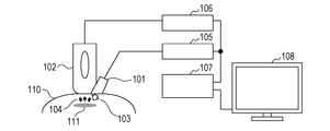
- Fig. 1 is a diagram showing the configuration of a photoacoustic tomography apparatus according to a first embodiment of the present invention.
- Fig. 2 is a diagram showing a measurement-mode selection window according to the first embodiment of the present invention.
- Fig. 3 is a flowchart of a measuring sequence according to the first embodiment of the present invention.
- Fig. 4 is a diagram showing a measurement-mode selection window according to a second embodiment of the present invention.
- a hand-held PAT apparatus in which an operator can manually operate a probe for detecting photoacoustic waves will be described by way of example.
- Fig. 1 shows the configuration of a PAT apparatus, which is an object-information acquisition apparatus according to this embodiment.
- This PAT apparatus incudes a light-emitting unit 101 serving as a light source, an ultrasonic probe 102 serving as a photoacoustic-wave detecting unit, a light-emission control unit 105, a probe control unit 106, and an apparatus control unit 107.
- the light-emitting unit 101 is a device that emits pulsed light to an object.
- the light-emitting unit 101 may be a laser light source capable of outputting high power, such as a solid-state laser, a gas laser, a dye laser, or a semiconductor laser.
- the light-emitting unit 101 is not limited to the laser light source but may be a light-emitting diode or a flash lamp.
- the emission timing, pulse width, intensity, and so on of the pulsed light are controlled by the light-emission control unit 105.
- the number of the light-emitting unit 101 does not need to be one; a plurality of light-emitting units may be used to irradiate the object from a plurality of directions to eliminate blind spots.
- the pulse width of the pulsed light generated from the light-emitting unit 101 may be about 10 to 50 nanoseconds.
- the wavelength of the pulsed light may be a wavelength at which the pulsed light is propagated to a region to be visualized in the object. Specifically, for a living organism, 700 nm or more and 1,100 nm or less are preferably. More specifically, the wavelength can be varied in the range of 720-880 nm using a titanium-sapphire laser, which is a solid-state laser. A dye laser with a wavelength of 580 nm is used as needed.
- the light-emitting unit 101 may not include a light source; for example, light output from a light source provided outside the light-emitting unit 101 may be introduced.
- photoacoustic waves 104 are generated from the absorber 111.
- the generated photoacoustic waves 104 are received by the ultrasonic probe 102 including devices capable of detecting ultrasonic waves.
- the received signal is converted to an analog electrical signal.
- the analog electrical signal is transmitted to the probe control unit 106, where it is amplified by an amplifier of the probe control unit 106, and is then converted to a digital signal by an analog-to-digital converter.
- the obtained digital signal is transmitted to the apparatus control unit 107.
- the timing of reception of the ultrasonic waves is controlled by the apparatus control unit 107 so as to synchronize with the light emission of the light-emitting unit 101.
- the ultrasonic probe 102 serving as a photoacoustic-wave detecting unit is a single probe.
- the ultrasonic probe 102 may be highly sensitive and have a wide frequency band.
- Examples of devices mounted to the ultrasonic probe 102 that meet the requirements include piezoelectric ceramics, such as lead zirconate titanate (PZT), a capacitive micromachined ultrasonic transducer (CMUT), and other transducers.
- PZT lead zirconate titanate
- CMUT capacitive micromachined ultrasonic transducer
- a photoacoustic wave receiving surface of the ultrasonic probe 102 may be either flat or curved along the external form of the object.
- 256 devices may be arrayed in a straight line at 2-mm pitch.
- the devices is not limited to be arrayed in a straight line but may be arrayed in two-dimensions or concentrically.
- the photoacoustic-wave receiving surface of the ultrasonic probe 102 may have a hemispherical form around which a plurality of devices are arrayed in a concentric form or a spiral form. The hemispherical receiving surface is suitable when the object is a breast of a living organism.
- the photoacoustic-wave receiving surface may have a cylindrical form or a semicylindrical form on which a plurality of devices are arrayed.
- the cylindrical or semicylindrical receiving surface is suitable when the object is an arm or a leg of a living organism.
- the central reception frequency of the ultrasonic probe 102 can be varied, for example, within 2-20 MHz.
- the central reception frequency of the photoacoustic waves detected by the ultrasonic probe 102 can be changed by changing the central reception frequency.
- the central reception frequency of the ultrasonic probe 102 is a frequency at which the ultrasonic probe 102 has high sensitivity, typically, the highest sensitivity.
- a plurality of devices having different central reception frequencies may be disposed on the receiving surface of the ultrasonic probe 102, so that the central reception frequency of the ultrasonic probe 102 can be changed by switching between devices that use an obtained electrical signal.
- the central reception frequency may be switched on the receiving surface of the ultrasonic probe 102 on which devices with low reception frequencies and devices with high reception frequencies are disposed.
- the electrical signal obtained from the photoacoustic waves is sampled at a sampling frequency of 50 MHz, and 1,024 samples are obtained.
- the digital signal obtained using the analog-to-digital converter has signed 12 bits.
- the apparatus control unit 107 serves as a measurement-mode selecting unit that selects a measurement mode: controls the light-emitting unit 101 and the ultrasonic probe 102; and reconstructs an image based on the photoacoustic waves detected by the ultrasonic probe 102, that is, generates image data.
- the apparatus control unit 107 also serves as a measurement-condition determination unit and an image processing unit.
- the apparatus control unit also serves as a display control unit that causes a display device 108 to display an image based on the generated image data.
- the apparatus control unit 107 includes a user interface, allowing change of measurement parameters, start and termination of the measurement, selection of a method of image processing, storage of object information and an image, analysis of data, and so on to be selected in accordance with an instruction from the operator.
- the apparatus control unit 107 may include a display as a user interface, so that the operator can perform the above selection with an operation menu on the display.
- the display of the apparatus control unit 107 may be a touch panel.
- the unit for reconstructing an image may be either a computer independent of the apparatus control unit 107 and including a CPU, a main storage unit, and an auxiliary storage unit, or specifically designed hardware.
- the apparatus control unit 107 may include a display control unit that controls display on a display device, a light-source control unit that controls the light source, and a detecting-unit control unit that controls the acoustic-wave detecting unit.
- Fig. 2 shows a measurement-mode selection window 201 according to this embodiment.
- the selection window 201 may be displayed on the display device 108 or may be displayed on the display of the apparatus control unit 107 if provided.
- two choices “Basic Menu” and “Option” are displayed on a measurement menu from which the operator can select.
- the "Basic Menu” field allows the operator to select “Surface of Body” or “Inside of Body”.
- the “Option” field allows the operator to select at least one of "Oxygen Saturation", “Contrast Medium”, and "Ultrasonic Waves".
- the reason why one of "Surface of Body” and “Inside of Body” can be selected in “Basic Menu” is that the wavelength of pulsed light applied to the object and the reception frequency of the photoacoustic waves can be roughly classified depending on whether the measurement is for the surface of body or the inside of body.
- the operator selects measurement of the surface of body or measurement of the inside of body on the "Basic Menu” using a radio button 202.
- the operator further selects options, such as "Oxygen Saturation”, “Contrast Medium”, and “Ultrasonic Waves” as necessary.
- the "Oxygen Saturation” is an option item for calculating and displaying oxygen saturation in a image reconstruction region of the object.
- the "Contrast Medium” is an option item that is selected when an object given a contrast medium is to be measured.
- the "Ultrasonic Waves” is an option item for acquiring an ultrasonic echo image by applying ultrasonic waves to an object and detecting reflected ultrasonic waves.
- the source of the ultrasonic waves applied to the object when “Ultrasonic Waves” is selected may be disposed on the ultrasonic probe 102.
- a "Run” button 204 is pressed after "Basic Menu” and “Option” are selected, a source wavelength and a central reception frequency of photoacoustic waves suitable for the measurement mode are automatically determined by the apparatus control unit 107.
- “Basic Menu” is an exclusive or, while “Option” allows the operator to select a plurality of choices at the same time.
- the apparatus control unit 107 automatically sets the source wavelengths of the pulsed lights to 756 nm and 797 nm, and the central reception frequency of the ultrasonic probe 102 to 3 MHz. Since a breast needs to be measured to a depth of about 4 cm, near-infrared light having a long light penetration depth is used for source pulsed light.
- the central reception frequency of the ultrasonic probe 102 is set to a low frequency of about 3 MHz to draw a relatively large structure, such as a tumor or a thick blood vessel in a breast.
- oxygen saturation is superimposed on a sound level distribution for display.
- Another method of display is displaying an image showing a sound level distribution and an image showing oxygen saturation side by side.
- a method of display may either be automatically determined by the apparatus control unit 107 in response to selection of a measurement mode or be selected by the operator.
- the apparatus control unit 107 automatically sets the source wavelength of the pulsed light to 580 nm, and the central reception frequency of the ultrasonic probe 102 to 20 MHz. This is because observation in the range of around 5 mm is enough to perform measurement on a skin or the like. This allows visible light with a wavelength shorter than that selected for measurement on "Inside of Body", that is, visible light with a short penetration length, to be used for the source wavelength.
- the photoacoustic waves needs to be set to a high central frequency because photoacoustic waves have to be detected at high resolution. Since the central reception frequency differs between measurement on "Surface of Body” and measurement on “Inside of Body”, the resolution of measurement differs. This results in different pixel resolutions of the images. Therefore, for measurement on “Surface of Body”, interpolation may be performed to prevent the difference in resolution from being viewed in the displayed images.
- “Surface of Body” is a relatively shallow region from the surface of the object to a depth of about 1 cm.
- the source wavelength is 780 nm.
- a menu that prompts the operator to select the kind of contrast medium may be further displayed.
- the apparatus control unit 107 selects a source wavelength suitable for the contrast medium given to the object.
- time-series images are displayed as a method of displaying images. An image displayed on the display device 108 may be switched in sequence in a slide show format, or alternatively, a plurality of images may be displayed side by side in one window. A difference from the first image may be displayed to make it easy to know a change with time.
- an image showing oxygen saturation may be interposed on an image acquired by measuring ultrasonic waves, of ultrasonic waves applied by the ultrasonic probe 102, reflected by the object.
- the ultrasonic probe 102 switches between reception of photoacoustic waves and transmission and reception of ultrasonic waves for usage.
- an item button 203 can be used. For example, when a "Surface of Body” button is pressed, setting for a part, such as a face, an arm, or a neck, and an observation target, such as a melanoma or a tumor, can be performed. Although the setting in this case is classified into “Surface of Body” and "Inside of Body", a selection window for measurement parts, such as a face, an arm, a neck, and a breast, may be displayed. For each of the parts, "Option" as shown in Fig. 2 may be set.
- a plurality of ultrasonic probes 102 with different central reception frequencies may be provided so that an ultrasonic probe 102 to be used can be changed depending on the details of "Basic Menu” and "Option” selected by the operator.
- the ultrasonic probe 102 may be detachable so that an ultrasonic probe 102 to be used can be replaced depending on the details of "Basic Menu” and "Option” selected by the operator.
- a message that tells an ultrasonic probe 102 to be used to the operator may be displayed on at least one of the display of the apparatus control unit 107 and the display device 108.
- the individual ultrasonic probes 102 may be differently shaped in the form of the receiving surface to the measurement target to make a good contact therewith.
- a window for selecting the kind of the object may be displayed before the selection window 201 is displayed.
- the selection window 201 shown in Fig. 2 is displayed.
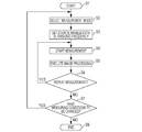
- Fig. 3 is a flowchart of a measuring sequence of this embodiment.
- the object measuring sequence is started from Step S1.
- the apparatus control unit 107 causes the selection window 201 to be displayed on its display or the display device 108.
- Step S2 is the process of selecting a measurement mode.
- the apparatus control unit 107 displays the selection window 201 on the display of the apparatus control unit 107 or the display device 108 to prompt the operator to select a measurement mode.
- the operator selects a measurement mode.
- the operator selects "Inside of Body” in "Basic Menu” and selects "Oxygen Saturation” and “Ultrasonic Waves” in “Option”.
- Step S3 is the process of determining measurement conditions corresponding to the measurement mode selected at step S2. Since "Inside of Body”, “Oxygen Saturation”, and “Ultrasonic Waves” are selected at step S2, the apparatus control unit 107 sets two source wavelengths 756 nm and 797 nm for the pulsed light and sets the central reception frequency of the photoacoustic waves detected by the ultrasonic probe 102 to 3 MHz. When a plurality of light sources are used, the optical path of light emitted from a light source corresponding to a wavelength selected as necessary is switched so that the light is applied to a target region of the object. At this step, the ultrasonic wave circuit is switched between transmission and reception of ultrasonic waves. After completion of the setting, the process goes to step S4.
- the measurement is started from step S4.
- the operator applies gel for acoustic coupling to the target region and brings the ultrasonic probe 102 of the PAT apparatus into contact therewith.
- the measurement is started with the ultrasonic probe 102 in contact.
- ultrasonic echo measurement is performed using the ultrasonic probe 102 to search for a desired measurement region from which photoacoustic waves are to be obtained.
- the ultrasonic echo measurement is performed on the desired region, and then photoacoustic measurement is performed.
- the switching from the ultrasonic echo measurement to the photoacoustic measurement may be performed in accordance with an instruction from the operator using an operation button.
- the ultrasonic echo measurement and the photoacoustic measurement may be automatically switched therebetween.
- the probe control unit 106 transmits and receives ultrasonic waves and sets the central reception frequency to 12 MHz, and for photoacoustic waves, the probe control unit 106 sets the central reception frequency to 3 MHz.
- the ultrasonic probe 102 can operate also as an ultrasonic-wave generating unit.
- the photoacoustic measurement is performed for both of a wavelength of 756 nm and a wavelength of 797 nm of the pulsed light. In this case, the ultrasonic waves probe 102 switches the central reception frequency between 3 MHz and 12 MHz using an electrical filter.
- step S5 an image is displayed.
- Data obtained until step S4 is an ultrasonic echo image and photoacoustic images acquired from pulsed light with a frequency of 756 nm and pulsed light with a frequency of 797 nm.
- An image of oxygen saturation can be calculated from image data on which the photoacoustic images of 756 nm and 797 nm are based.
- the image of the oxygen saturation is superimposed on the ultrasonic echo image and is displayed on the display device 108.
- step S6 the operator determines whether a repetition of the measurement is required. If the operator determines that a desired image is acquired by checking the image, the operator inputs an instruction to terminate the measurement to complete the measurement. The completion of the measurement can be input via, for example, the user interface of the apparatus control unit 107. If the target object is a breast, the same measurement is performed on the other breast of the identical object as needed. If the operator determines that repeated measurement is necessary, or the same measurement is to be performed on the other breast, the process returns to step S4 for measurement.
- step S7 the operator determines whether the measurement conditions need to be changed. If measurement on, not the internal part of the breast, but another part, such as a skin, is needed, the process returns to step S2 for selecting a measurement mode. Also for a case where measurement is performed on the same part under conditions suitable for, for example, an object given a contrast medium, the process returns to step S2 for selecting a measurement mode. If there is no need to change the measurement conditions, the process goes to step S8.
- step S8 the measuring sequence is completed.
- a second embodiment is an object-information acquisition apparatus in which measurement parameters can be set using a tab-format selection window. Differences from the first embodiment will be mainly described hereinbelow.
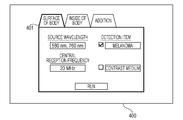
- Fig. 4 shows a measurement-mode selection window 400 according to this embodiment.
- Tabs 401 are used to select the details of setting.
- an "Addition” tab is provided in addition to a "Surface of Body” tab and an “Inside of Body” tab for a measurement mode, allowing the operator to set desired measurement parameters.
- the operator first selects one of the "Surface of Body” tab, the “Inside of Body” tab, and the “Addition” tab in the selection window 400.
- "Surface of Body” tab "580 nm” is displayed in a “Source Wavelength” field as the source wavelength of the pulsed light, and "20 MHz” is displayed in a “Central Reception Frequency” field as the central reception frequency of the ultrasonic probe 102.
- These two values are preset values that are automatically determined by selecting the "Surface of Body” tab.
- "Melanoma” as a measurement mode from "Detection Item
- "760 nm” is further displayed in the "Source Wavelength” field. Since Fig.
- the object measuring sequence is started from step S1.
- the apparatus control unit 107 causes the selection window 400 to be displayed on its display or the display device 108.
- a measurement mode is selected on the selection window 400 in Fig. 4.
- the operator selects the "Surface of Body” tab and selects "Melanoma” in "Detection Item” as an option.
- Step S3 is the process of determining measurement conditions corresponding to the measurement mode selected at step S2. Since "Surface of Body” and “Melanoma” are selected at step S2, the apparatus control unit 107 sets two source wavelengths, 580 nm and 760 nm, for the pulsed light and sets the central reception frequency of the photoacoustic waves detected by the ultrasonic probe 102 to 20 MHz.
- the measurement is started from step S4. Before the measurement, the operator applies gel for acoustic coupling to the target region and brings the ultrasonic probe 102 into contact with a desired position.
- the photoacoustic measurement is performed for each of the source wavelengths 580 nm and 760 nm of the pulsed light.
- the switching between the source wavelengths is achieved by switching between the optical paths of a dye laser and a titanium-sapphire laser, for example.
- an image is displayed.
- a method for displaying an image is selected which allows the relationship between melanoma and its peripheral blood vessels to be viewed from measurement images acquired at the source wavelengths of 580 nm and 760 nm of the pulsed light, and the images are displayed in a superimposed manner.
- step S6 the operator determines whether a repetition of the measurement is required. If the operator determines that a desired image is acquired by checking the image, the measurement is completed. If the operator determines that repeated measurement is necessary, or the same measurement is to be performed on another part, the process returns to step S4 for measurement.
- step S7 the operator determines whether the measurement conditions need to be changed. If measurement on another par is needed, the process returns to step S2 for selecting a measurement mode. If there is no need to perform measurement on another part, the process goes to step S8.
- step S8 the measuring sequence is completed.
- the hand-held PAT apparatus in which an operator can move with the ultrasonic probe 102 in hand has been described as an example.
- the configuration of the PAT apparatus is given for mere illustration and is not intended to limit the invention.
- a floor-mounted object-information acquisition apparatus or an ultrasonic probe that can be moved on a predetermined path or within a predetermined range may be employed.
- the central reception frequency of the ultrasonic probe 102 is switched depending on a selected measurement mode.
- a conceivable method for achieving the switching is providing a plurality of probes with different central reception frequencies and using a probe corresponding to a selected measurement mode.
- the apparatus control unit 107 may activate only a probe to be used in a selected measurement mode. In this case, the activated probe may be displayed on the display device 108 to increase the convenience of the operator.
- the ultrasonic probe 102 may be interchangeable so that an ultrasonic probe 102 having a central reception frequency for a selected measurement mode can be used.
- the apparatus control unit 107 may be configured to determine the pulse width of the light emitted by the light-emitting unit 101 depending on a selected measurement mode.
- the above object-information acquisition apparatus can be used as a medical diagnostic imaging apparatus when the object is a biological substance.
- the apparatus can image the distribution of optical characteristic values in a living organism and the density distribution of substances constituting the biological tissue acquired from the information to make a diagnosis of a tumor or a vascular disease or monitor a chemical treatment over time.
- the apparatus can also be applied o a nondestructive examination on a nonliving substance.
- the above embodiments show a case where the wavelength of pulsed light output from the light-emitting unit 101 serving as a light source and the central reception frequency of acoustic waves detected by the ultrasonic probe 102 serving as an acoustic-wave detecting unit are determined in advance.
- another condition on the light source may be determined in advance.
- another condition on the ultrasonic probe 102 may be determined in advance.
- a storage unit that stores first parameters on the light source (for example, a wavelength, a pulse width, an amplitude, and a pulse interval) and second parameters on the ultrasonic probe 102 (for example, a central reception frequency, a sampling frequency, and a sampling interval) may be provided.
- the storage unit may store a table in which the first and second parameters are associated with measurement modes. If conditions on the light source ad the acoustic-wave detecting unit are determined in advance for each measurement mode, various conditions can be automatically set when the operator selects a measurement mode.
- the present invention can also be implemented by supplying a program for implementing one or more functions of the above embodiments to a system or apparatus via a network or a storage medium and by reading and executing the program with one or more processors of a computer of the system or apparatus.
- the present invention can also be implemented by a circuit that implements one or more functions, for example, an application specific integrated circuit (ASIC).
- ASIC application specific integrated circuit
Landscapes
- Health & Medical Sciences (AREA)
- Life Sciences & Earth Sciences (AREA)
- Physics & Mathematics (AREA)
- Surgery (AREA)
- General Health & Medical Sciences (AREA)
- Engineering & Computer Science (AREA)
- Biomedical Technology (AREA)
- Heart & Thoracic Surgery (AREA)
- Medical Informatics (AREA)
- Molecular Biology (AREA)
- Biophysics (AREA)
- Animal Behavior & Ethology (AREA)
- Pathology (AREA)
- Public Health (AREA)
- Veterinary Medicine (AREA)
- Nuclear Medicine, Radiotherapy & Molecular Imaging (AREA)
- Radiology & Medical Imaging (AREA)
- Acoustics & Sound (AREA)
- Gynecology & Obstetrics (AREA)
- Optics & Photonics (AREA)
- Ultra Sonic Daignosis Equipment (AREA)
Priority Applications (2)
| Application Number | Priority Date | Filing Date | Title |
|---|---|---|---|
| CN201580052612.8A CN106714672A (zh) | 2014-09-29 | 2015-09-24 | 被检体信息获取装置 |
| US15/513,400 US20170303794A1 (en) | 2014-09-29 | 2015-09-24 | Object-information acquisition apparatus |
Applications Claiming Priority (2)
| Application Number | Priority Date | Filing Date | Title |
|---|---|---|---|
| JP2014-199183 | 2014-09-29 | ||
| JP2014199183A JP6501474B2 (ja) | 2014-09-29 | 2014-09-29 | 被検体情報取得装置 |
Publications (1)
| Publication Number | Publication Date |
|---|---|
| WO2016051734A1 true WO2016051734A1 (en) | 2016-04-07 |
Family
ID=54292879
Family Applications (1)
| Application Number | Title | Priority Date | Filing Date |
|---|---|---|---|
| PCT/JP2015/004844 Ceased WO2016051734A1 (en) | 2014-09-29 | 2015-09-24 | Object-information acquisition apparatus |
Country Status (4)
| Country | Link |
|---|---|
| US (1) | US20170303794A1 (enExample) |
| JP (1) | JP6501474B2 (enExample) |
| CN (1) | CN106714672A (enExample) |
| WO (1) | WO2016051734A1 (enExample) |
Cited By (2)
| Publication number | Priority date | Publication date | Assignee | Title |
|---|---|---|---|---|
| EP3338626A1 (en) * | 2016-12-26 | 2018-06-27 | Samsung Medison Co., Ltd. | Photoacoustic imaging diagnosis apparatus and methods of controlling the same |
| EP3488224A4 (en) * | 2016-07-25 | 2019-07-31 | Photosound Technologies, Inc. | INSTRUMENT FOR DETECTING CO REGISTERED ORTHOGONAL FLUORESCENCE AND PHOTOACUSTIC VOLUMETRIC PROJECTIONS OF TISSUE AND METHOD FOR USE THEREOF |
Families Citing this family (7)
| Publication number | Priority date | Publication date | Assignee | Title |
|---|---|---|---|---|
| US10257591B2 (en) * | 2016-08-02 | 2019-04-09 | Pindrop Security, Inc. | Call classification through analysis of DTMF events |
| JP6790235B2 (ja) | 2017-03-29 | 2020-11-25 | 富士フイルム株式会社 | 光音響画像生成装置 |
| US20180368696A1 (en) * | 2017-06-23 | 2018-12-27 | Canon Kabushiki Kaisha | Object information acquiring apparatus and object information acquiring method |
| WO2019044593A1 (ja) * | 2017-08-29 | 2019-03-07 | 富士フイルム株式会社 | 光音響画像生成装置および画像取得方法 |
| JP2019118457A (ja) * | 2017-12-28 | 2019-07-22 | キヤノン株式会社 | 光音響装置ならびに情報処理装置および方法 |
| JP2020028396A (ja) * | 2018-08-21 | 2020-02-27 | キヤノン株式会社 | 情報処理装置、システム、情報処理方法、プログラム |
| CN115444434B (zh) * | 2022-11-10 | 2023-03-24 | 深圳市心流科技有限公司 | 一种体征检测方法、体征检测装置、终端设备及存储介质 |
Citations (4)
| Publication number | Priority date | Publication date | Assignee | Title |
|---|---|---|---|---|
| US20040267124A1 (en) * | 2003-06-24 | 2004-12-30 | Roundhill David N. | Automatic setup system and method for ultrasound imaging systems |
| US20130253317A1 (en) * | 2010-12-15 | 2013-09-26 | Koninklijke Philips Electronics N.V. | Ultrasound imaging system with patient-specific settings |
| US20130279920A1 (en) * | 2011-11-02 | 2013-10-24 | Seno Medical Instruments, Inc. | Repeatably alignable fiber optic connector |
| US20140182383A1 (en) * | 2012-12-28 | 2014-07-03 | Canon Kabushiki Kaisha | Object information obtaining device, display method, and non-transitory computer-readable storage medium |
Family Cites Families (16)
| Publication number | Priority date | Publication date | Assignee | Title |
|---|---|---|---|---|
| BR0309578A (pt) * | 2002-04-22 | 2007-03-06 | Marcio Marc Aurelio Mart Abreu | aparelho e método para a medição de parámetros biológicos |
| JP5322600B2 (ja) * | 2008-11-19 | 2013-10-23 | 株式会社東芝 | 超音波診断装置 |
| JP5405230B2 (ja) * | 2009-08-11 | 2014-02-05 | 株式会社東芝 | 超音波診断装置、超音波診断装置の制御方法、及び超音波プローブ管理システム |
| EP2504808A2 (en) * | 2009-11-25 | 2012-10-03 | Merge Healthcare Incorporated | Systems and methods for remote diagnostic imaging |
| JP2012010845A (ja) * | 2010-06-30 | 2012-01-19 | Hitachi Aloka Medical Ltd | 超音波診断装置 |
| US9163980B2 (en) * | 2010-09-17 | 2015-10-20 | Seno Medical Instruments, Inc. | Light output calibration in an optoacoustic system |
| US8686335B2 (en) * | 2011-12-31 | 2014-04-01 | Seno Medical Instruments, Inc. | System and method for adjusting the light output of an optoacoustic imaging system |
| JP2012176000A (ja) * | 2011-02-25 | 2012-09-13 | Konica Minolta Medical & Graphic Inc | 超音波診断装置、医用画像管理システム及びプログラム |
| JP6010306B2 (ja) * | 2011-03-10 | 2016-10-19 | 富士フイルム株式会社 | 光音響計測装置 |
| US20130338475A1 (en) * | 2012-06-13 | 2013-12-19 | Seno Medical Instruments, Inc. | Optoacoustic imaging system with fiber optic cable |
| JP2013128722A (ja) * | 2011-12-22 | 2013-07-04 | Fujifilm Corp | 光音響画像化方法および装置 |
| US9119550B2 (en) * | 2012-03-30 | 2015-09-01 | Siemens Medical Solutions Usa, Inc. | Magnetic resonance and ultrasound parametric image fusion |
| US9610043B2 (en) * | 2012-06-13 | 2017-04-04 | Seno Medical Instruments, Inc. | System and method for producing parametric maps of optoacoustic data |
| EP2934335A4 (en) * | 2012-12-21 | 2016-07-20 | Volcano Corp | ADAPTIVE INTERFACE FOR A MEDICAL IMAGING SYSTEM |
| KR102107728B1 (ko) * | 2013-04-03 | 2020-05-07 | 삼성메디슨 주식회사 | 휴대용 초음파 장치, 휴대용 초음파 시스템 및 초음파 진단 방법 |
| WO2015073357A1 (en) * | 2013-11-13 | 2015-05-21 | Volcano Corporation | Visually optimized intravascular imaging and associated devices, systems, and methods |
-
2014
- 2014-09-29 JP JP2014199183A patent/JP6501474B2/ja not_active Expired - Fee Related
-
2015
- 2015-09-24 CN CN201580052612.8A patent/CN106714672A/zh active Pending
- 2015-09-24 US US15/513,400 patent/US20170303794A1/en not_active Abandoned
- 2015-09-24 WO PCT/JP2015/004844 patent/WO2016051734A1/en not_active Ceased
Patent Citations (5)
| Publication number | Priority date | Publication date | Assignee | Title |
|---|---|---|---|---|
| US20040267124A1 (en) * | 2003-06-24 | 2004-12-30 | Roundhill David N. | Automatic setup system and method for ultrasound imaging systems |
| US20130253317A1 (en) * | 2010-12-15 | 2013-09-26 | Koninklijke Philips Electronics N.V. | Ultrasound imaging system with patient-specific settings |
| US20130279920A1 (en) * | 2011-11-02 | 2013-10-24 | Seno Medical Instruments, Inc. | Repeatably alignable fiber optic connector |
| US20140182383A1 (en) * | 2012-12-28 | 2014-07-03 | Canon Kabushiki Kaisha | Object information obtaining device, display method, and non-transitory computer-readable storage medium |
| JP2014140717A (ja) * | 2012-12-28 | 2014-08-07 | Canon Inc | 被検体情報取得装置、表示方法、およびプログラム |
Cited By (3)
| Publication number | Priority date | Publication date | Assignee | Title |
|---|---|---|---|---|
| EP3488224A4 (en) * | 2016-07-25 | 2019-07-31 | Photosound Technologies, Inc. | INSTRUMENT FOR DETECTING CO REGISTERED ORTHOGONAL FLUORESCENCE AND PHOTOACUSTIC VOLUMETRIC PROJECTIONS OF TISSUE AND METHOD FOR USE THEREOF |
| EP3338626A1 (en) * | 2016-12-26 | 2018-06-27 | Samsung Medison Co., Ltd. | Photoacoustic imaging diagnosis apparatus and methods of controlling the same |
| US11020007B2 (en) | 2016-12-26 | 2021-06-01 | Samsung Medison Co., Ltd. | Photoacoustic imaging diagnosis apparatus and method of controlling the same |
Also Published As
| Publication number | Publication date |
|---|---|
| JP6501474B2 (ja) | 2019-04-17 |
| JP2016067552A (ja) | 2016-05-09 |
| CN106714672A (zh) | 2017-05-24 |
| US20170303794A1 (en) | 2017-10-26 |
Similar Documents
| Publication | Publication Date | Title |
|---|---|---|
| WO2016051734A1 (en) | Object-information acquisition apparatus | |
| JP6053512B2 (ja) | 被検体情報取得装置およびその制御方法 | |
| US20160150973A1 (en) | Subject information acquisition apparatus | |
| JP6335612B2 (ja) | 光音響装置、処理装置、処理方法、及びプログラム | |
| JP2014140718A (ja) | 被検体情報取得装置、表示方法、およびプログラム | |
| EP3266378A1 (en) | Apparatus, method, and program for obtaining information derived from ultrasonic waves and photoacoustic waves | |
| CN109475345A (zh) | 用于显示超声图像和光声图像的装置、方法和程序 | |
| JP2012239784A (ja) | 光音響撮像装置およびその作動方法 | |
| JP2018126454A (ja) | 被検体情報取得装置および表示方法 | |
| JP2016120158A (ja) | 被検体情報取得装置 | |
| US20180368696A1 (en) | Object information acquiring apparatus and object information acquiring method | |
| US20160150990A1 (en) | Photoacoustic apparatus, subject information acquisition method, and program | |
| US10849537B2 (en) | Processing apparatus and processing method | |
| JP6664176B2 (ja) | 光音響装置、情報処理方法、およびプログラム | |
| US20190000322A1 (en) | Photoacoustic probe and photoacoustic apparatus including the same | |
| US20180325380A1 (en) | Subject information acquisition device and subject information acquisition method | |
| CN105640495B (zh) | 光声装置 | |
| JP2020018467A (ja) | 情報処理装置、情報処理方法、プログラム | |
| JP2019155004A (ja) | 光音響装置および被検体情報取得方法 | |
| US20180299763A1 (en) | Information processing apparatus, object information acquiring apparatus, and information processing method | |
| KR20180106902A (ko) | 광음향장치 및 그 제어 방법, 및 광음향 프로브 | |
| JP6847234B2 (ja) | 光音響画像生成装置 | |
| JP2018082999A (ja) | 超音波プローブ | |
| JP2017039031A (ja) | 被検体情報取得装置およびその制御方法 | |
| JP2020096750A (ja) | 光音響画像化装置、制御方法及びプログラム |
Legal Events
| Date | Code | Title | Description |
|---|---|---|---|
| 121 | Ep: the epo has been informed by wipo that ep was designated in this application |
Ref document number: 15778769 Country of ref document: EP Kind code of ref document: A1 |
|
| WWE | Wipo information: entry into national phase |
Ref document number: 15513400 Country of ref document: US |
|
| NENP | Non-entry into the national phase |
Ref country code: DE |
|
| 122 | Ep: pct application non-entry in european phase |
Ref document number: 15778769 Country of ref document: EP Kind code of ref document: A1 |