WO2016047457A1 - 物標検出装置 - Google Patents
物標検出装置 Download PDFInfo
- Publication number
- WO2016047457A1 WO2016047457A1 PCT/JP2015/075746 JP2015075746W WO2016047457A1 WO 2016047457 A1 WO2016047457 A1 WO 2016047457A1 JP 2015075746 W JP2015075746 W JP 2015075746W WO 2016047457 A1 WO2016047457 A1 WO 2016047457A1
- Authority
- WO
- WIPO (PCT)
- Prior art keywords
- target
- area
- axis
- respect
- vehicle
- Prior art date
Links
- 238000001514 detection method Methods 0.000 title claims abstract description 53
- 230000000116 mitigating effect Effects 0.000 description 50
- 238000000034 method Methods 0.000 description 25
- 230000008569 process Effects 0.000 description 22
- 238000012937 correction Methods 0.000 description 7
- 230000009467 reduction Effects 0.000 description 7
- 238000012545 processing Methods 0.000 description 5
- 230000008859 change Effects 0.000 description 4
- 238000002485 combustion reaction Methods 0.000 description 2
- 238000010586 diagram Methods 0.000 description 2
- 238000013459 approach Methods 0.000 description 1
- 230000005540 biological transmission Effects 0.000 description 1
- 238000004891 communication Methods 0.000 description 1
- 239000000470 constituent Substances 0.000 description 1
- 239000000446 fuel Substances 0.000 description 1
- 238000002347 injection Methods 0.000 description 1
- 239000007924 injection Substances 0.000 description 1
- 230000007257 malfunction Effects 0.000 description 1
- 238000011946 reduction process Methods 0.000 description 1
Images

Classifications
-
- G—PHYSICS
- G01—MEASURING; TESTING
- G01S—RADIO DIRECTION-FINDING; RADIO NAVIGATION; DETERMINING DISTANCE OR VELOCITY BY USE OF RADIO WAVES; LOCATING OR PRESENCE-DETECTING BY USE OF THE REFLECTION OR RERADIATION OF RADIO WAVES; ANALOGOUS ARRANGEMENTS USING OTHER WAVES
- G01S3/00—Direction-finders for determining the direction from which infrasonic, sonic, ultrasonic, or electromagnetic waves, or particle emission, not having a directional significance, are being received
- G01S3/80—Direction-finders for determining the direction from which infrasonic, sonic, ultrasonic, or electromagnetic waves, or particle emission, not having a directional significance, are being received using ultrasonic, sonic or infrasonic waves
- G01S3/86—Direction-finders for determining the direction from which infrasonic, sonic, ultrasonic, or electromagnetic waves, or particle emission, not having a directional significance, are being received using ultrasonic, sonic or infrasonic waves with means for eliminating undesired waves, e.g. disturbing noises
-
- B—PERFORMING OPERATIONS; TRANSPORTING
- B60—VEHICLES IN GENERAL
- B60R—VEHICLES, VEHICLE FITTINGS, OR VEHICLE PARTS, NOT OTHERWISE PROVIDED FOR
- B60R21/00—Arrangements or fittings on vehicles for protecting or preventing injuries to occupants or pedestrians in case of accidents or other traffic risks
-
- B—PERFORMING OPERATIONS; TRANSPORTING
- B60—VEHICLES IN GENERAL
- B60W—CONJOINT CONTROL OF VEHICLE SUB-UNITS OF DIFFERENT TYPE OR DIFFERENT FUNCTION; CONTROL SYSTEMS SPECIALLY ADAPTED FOR HYBRID VEHICLES; ROAD VEHICLE DRIVE CONTROL SYSTEMS FOR PURPOSES NOT RELATED TO THE CONTROL OF A PARTICULAR SUB-UNIT
- B60W10/00—Conjoint control of vehicle sub-units of different type or different function
- B60W10/04—Conjoint control of vehicle sub-units of different type or different function including control of propulsion units
- B60W10/06—Conjoint control of vehicle sub-units of different type or different function including control of propulsion units including control of combustion engines
-
- B—PERFORMING OPERATIONS; TRANSPORTING
- B60—VEHICLES IN GENERAL
- B60W—CONJOINT CONTROL OF VEHICLE SUB-UNITS OF DIFFERENT TYPE OR DIFFERENT FUNCTION; CONTROL SYSTEMS SPECIALLY ADAPTED FOR HYBRID VEHICLES; ROAD VEHICLE DRIVE CONTROL SYSTEMS FOR PURPOSES NOT RELATED TO THE CONTROL OF A PARTICULAR SUB-UNIT
- B60W10/00—Conjoint control of vehicle sub-units of different type or different function
- B60W10/18—Conjoint control of vehicle sub-units of different type or different function including control of braking systems
-
- B—PERFORMING OPERATIONS; TRANSPORTING
- B60—VEHICLES IN GENERAL
- B60W—CONJOINT CONTROL OF VEHICLE SUB-UNITS OF DIFFERENT TYPE OR DIFFERENT FUNCTION; CONTROL SYSTEMS SPECIALLY ADAPTED FOR HYBRID VEHICLES; ROAD VEHICLE DRIVE CONTROL SYSTEMS FOR PURPOSES NOT RELATED TO THE CONTROL OF A PARTICULAR SUB-UNIT
- B60W30/00—Purposes of road vehicle drive control systems not related to the control of a particular sub-unit, e.g. of systems using conjoint control of vehicle sub-units, or advanced driver assistance systems for ensuring comfort, stability and safety or drive control systems for propelling or retarding the vehicle
- B60W30/08—Active safety systems predicting or avoiding probable or impending collision or attempting to minimise its consequences
- B60W30/09—Taking automatic action to avoid collision, e.g. braking and steering
-
- B—PERFORMING OPERATIONS; TRANSPORTING
- B60—VEHICLES IN GENERAL
- B60W—CONJOINT CONTROL OF VEHICLE SUB-UNITS OF DIFFERENT TYPE OR DIFFERENT FUNCTION; CONTROL SYSTEMS SPECIALLY ADAPTED FOR HYBRID VEHICLES; ROAD VEHICLE DRIVE CONTROL SYSTEMS FOR PURPOSES NOT RELATED TO THE CONTROL OF A PARTICULAR SUB-UNIT
- B60W30/00—Purposes of road vehicle drive control systems not related to the control of a particular sub-unit, e.g. of systems using conjoint control of vehicle sub-units, or advanced driver assistance systems for ensuring comfort, stability and safety or drive control systems for propelling or retarding the vehicle
- B60W30/08—Active safety systems predicting or avoiding probable or impending collision or attempting to minimise its consequences
- B60W30/095—Predicting travel path or likelihood of collision
-
- B—PERFORMING OPERATIONS; TRANSPORTING
- B60—VEHICLES IN GENERAL
- B60W—CONJOINT CONTROL OF VEHICLE SUB-UNITS OF DIFFERENT TYPE OR DIFFERENT FUNCTION; CONTROL SYSTEMS SPECIALLY ADAPTED FOR HYBRID VEHICLES; ROAD VEHICLE DRIVE CONTROL SYSTEMS FOR PURPOSES NOT RELATED TO THE CONTROL OF A PARTICULAR SUB-UNIT
- B60W50/00—Details of control systems for road vehicle drive control not related to the control of a particular sub-unit, e.g. process diagnostic or vehicle driver interfaces
- B60W50/08—Interaction between the driver and the control system
- B60W50/14—Means for informing the driver, warning the driver or prompting a driver intervention
-
- G—PHYSICS
- G01—MEASURING; TESTING
- G01S—RADIO DIRECTION-FINDING; RADIO NAVIGATION; DETERMINING DISTANCE OR VELOCITY BY USE OF RADIO WAVES; LOCATING OR PRESENCE-DETECTING BY USE OF THE REFLECTION OR RERADIATION OF RADIO WAVES; ANALOGOUS ARRANGEMENTS USING OTHER WAVES
- G01S13/00—Systems using the reflection or reradiation of radio waves, e.g. radar systems; Analogous systems using reflection or reradiation of waves whose nature or wavelength is irrelevant or unspecified
- G01S13/86—Combinations of radar systems with non-radar systems, e.g. sonar, direction finder
- G01S13/867—Combination of radar systems with cameras
-
- G—PHYSICS
- G01—MEASURING; TESTING
- G01S—RADIO DIRECTION-FINDING; RADIO NAVIGATION; DETERMINING DISTANCE OR VELOCITY BY USE OF RADIO WAVES; LOCATING OR PRESENCE-DETECTING BY USE OF THE REFLECTION OR RERADIATION OF RADIO WAVES; ANALOGOUS ARRANGEMENTS USING OTHER WAVES
- G01S13/00—Systems using the reflection or reradiation of radio waves, e.g. radar systems; Analogous systems using reflection or reradiation of waves whose nature or wavelength is irrelevant or unspecified
- G01S13/88—Radar or analogous systems specially adapted for specific applications
- G01S13/93—Radar or analogous systems specially adapted for specific applications for anti-collision purposes
- G01S13/931—Radar or analogous systems specially adapted for specific applications for anti-collision purposes of land vehicles
-
- G—PHYSICS
- G01—MEASURING; TESTING
- G01S—RADIO DIRECTION-FINDING; RADIO NAVIGATION; DETERMINING DISTANCE OR VELOCITY BY USE OF RADIO WAVES; LOCATING OR PRESENCE-DETECTING BY USE OF THE REFLECTION OR RERADIATION OF RADIO WAVES; ANALOGOUS ARRANGEMENTS USING OTHER WAVES
- G01S17/00—Systems using the reflection or reradiation of electromagnetic waves other than radio waves, e.g. lidar systems
- G01S17/86—Combinations of lidar systems with systems other than lidar, radar or sonar, e.g. with direction finders
-
- G—PHYSICS
- G01—MEASURING; TESTING
- G01S—RADIO DIRECTION-FINDING; RADIO NAVIGATION; DETERMINING DISTANCE OR VELOCITY BY USE OF RADIO WAVES; LOCATING OR PRESENCE-DETECTING BY USE OF THE REFLECTION OR RERADIATION OF RADIO WAVES; ANALOGOUS ARRANGEMENTS USING OTHER WAVES
- G01S7/00—Details of systems according to groups G01S13/00, G01S15/00, G01S17/00
- G01S7/02—Details of systems according to groups G01S13/00, G01S15/00, G01S17/00 of systems according to group G01S13/00
- G01S7/40—Means for monitoring or calibrating
- G01S7/4004—Means for monitoring or calibrating of parts of a radar system
- G01S7/4026—Antenna boresight
-
- G—PHYSICS
- G08—SIGNALLING
- G08G—TRAFFIC CONTROL SYSTEMS
- G08G1/00—Traffic control systems for road vehicles
- G08G1/16—Anti-collision systems
-
- G—PHYSICS
- G08—SIGNALLING
- G08G—TRAFFIC CONTROL SYSTEMS
- G08G1/00—Traffic control systems for road vehicles
- G08G1/16—Anti-collision systems
- G08G1/166—Anti-collision systems for active traffic, e.g. moving vehicles, pedestrians, bikes
-
- B—PERFORMING OPERATIONS; TRANSPORTING
- B60—VEHICLES IN GENERAL
- B60W—CONJOINT CONTROL OF VEHICLE SUB-UNITS OF DIFFERENT TYPE OR DIFFERENT FUNCTION; CONTROL SYSTEMS SPECIALLY ADAPTED FOR HYBRID VEHICLES; ROAD VEHICLE DRIVE CONTROL SYSTEMS FOR PURPOSES NOT RELATED TO THE CONTROL OF A PARTICULAR SUB-UNIT
- B60W50/00—Details of control systems for road vehicle drive control not related to the control of a particular sub-unit, e.g. process diagnostic or vehicle driver interfaces
- B60W50/08—Interaction between the driver and the control system
- B60W50/14—Means for informing the driver, warning the driver or prompting a driver intervention
- B60W2050/143—Alarm means
-
- B—PERFORMING OPERATIONS; TRANSPORTING
- B60—VEHICLES IN GENERAL
- B60W—CONJOINT CONTROL OF VEHICLE SUB-UNITS OF DIFFERENT TYPE OR DIFFERENT FUNCTION; CONTROL SYSTEMS SPECIALLY ADAPTED FOR HYBRID VEHICLES; ROAD VEHICLE DRIVE CONTROL SYSTEMS FOR PURPOSES NOT RELATED TO THE CONTROL OF A PARTICULAR SUB-UNIT
- B60W2420/00—Indexing codes relating to the type of sensors based on the principle of their operation
- B60W2420/40—Photo or light sensitive means, e.g. infrared sensors
- B60W2420/403—Image sensing, e.g. optical camera
-
- B60W2420/408—
-
- B—PERFORMING OPERATIONS; TRANSPORTING
- B60—VEHICLES IN GENERAL
- B60W—CONJOINT CONTROL OF VEHICLE SUB-UNITS OF DIFFERENT TYPE OR DIFFERENT FUNCTION; CONTROL SYSTEMS SPECIALLY ADAPTED FOR HYBRID VEHICLES; ROAD VEHICLE DRIVE CONTROL SYSTEMS FOR PURPOSES NOT RELATED TO THE CONTROL OF A PARTICULAR SUB-UNIT
- B60W2554/00—Input parameters relating to objects
-
- B—PERFORMING OPERATIONS; TRANSPORTING
- B60—VEHICLES IN GENERAL
- B60W—CONJOINT CONTROL OF VEHICLE SUB-UNITS OF DIFFERENT TYPE OR DIFFERENT FUNCTION; CONTROL SYSTEMS SPECIALLY ADAPTED FOR HYBRID VEHICLES; ROAD VEHICLE DRIVE CONTROL SYSTEMS FOR PURPOSES NOT RELATED TO THE CONTROL OF A PARTICULAR SUB-UNIT
- B60W30/00—Purposes of road vehicle drive control systems not related to the control of a particular sub-unit, e.g. of systems using conjoint control of vehicle sub-units, or advanced driver assistance systems for ensuring comfort, stability and safety or drive control systems for propelling or retarding the vehicle
- B60W30/08—Active safety systems predicting or avoiding probable or impending collision or attempting to minimise its consequences
-
- G—PHYSICS
- G01—MEASURING; TESTING
- G01S—RADIO DIRECTION-FINDING; RADIO NAVIGATION; DETERMINING DISTANCE OR VELOCITY BY USE OF RADIO WAVES; LOCATING OR PRESENCE-DETECTING BY USE OF THE REFLECTION OR RERADIATION OF RADIO WAVES; ANALOGOUS ARRANGEMENTS USING OTHER WAVES
- G01S13/00—Systems using the reflection or reradiation of radio waves, e.g. radar systems; Analogous systems using reflection or reradiation of waves whose nature or wavelength is irrelevant or unspecified
- G01S13/88—Radar or analogous systems specially adapted for specific applications
- G01S13/93—Radar or analogous systems specially adapted for specific applications for anti-collision purposes
- G01S13/931—Radar or analogous systems specially adapted for specific applications for anti-collision purposes of land vehicles
- G01S2013/93185—Controlling the brakes
-
- G—PHYSICS
- G01—MEASURING; TESTING
- G01S—RADIO DIRECTION-FINDING; RADIO NAVIGATION; DETERMINING DISTANCE OR VELOCITY BY USE OF RADIO WAVES; LOCATING OR PRESENCE-DETECTING BY USE OF THE REFLECTION OR RERADIATION OF RADIO WAVES; ANALOGOUS ARRANGEMENTS USING OTHER WAVES
- G01S13/00—Systems using the reflection or reradiation of radio waves, e.g. radar systems; Analogous systems using reflection or reradiation of waves whose nature or wavelength is irrelevant or unspecified
- G01S13/88—Radar or analogous systems specially adapted for specific applications
- G01S13/93—Radar or analogous systems specially adapted for specific applications for anti-collision purposes
- G01S13/931—Radar or analogous systems specially adapted for specific applications for anti-collision purposes of land vehicles
- G01S2013/932—Radar or analogous systems specially adapted for specific applications for anti-collision purposes of land vehicles using own vehicle data, e.g. ground speed, steering wheel direction
Definitions
- the present invention relates to a technique for detecting a target using a radar and a camera.
- Patent Document 1 a configuration for detecting a target using a radar and a camera has been proposed (see Patent Document 1). Specifically, in the configuration described in Patent Document 1, when the targets are detected independently by the millimeter wave radar and the monocular camera, and the positional relationship between the targets satisfies the determination criteria, those objects are detected. It is determined that the target is the same target.
- a target detection apparatus that detects a target using a radar and a camera, and determines whether or not they are the same target even when an axis deviation occurs. It is an object of the present invention to provide a target detection apparatus that can be implemented more accurately.
- the first specifying unit may be configured to set the vehicle width direction of the vehicle as the X-axis with respect to the first target detected based on the detection information by the radar.
- a first region including a first detection point that is a detection point representing a relative position of the first target with respect to a reference point on the XY plane with the vehicle length direction as the Y axis is specified.
- the second specifying unit is a second detection point that is a detection point representing a relative position of the second target with respect to a reference point on the XY plane with respect to the second target detected based on the image captured by the monocular camera. The second region including the point is specified.
- the axis deviation presence / absence acquisition unit acquires the presence / absence of an axis deviation indicating the deviation of the radar axis with respect to the reference azimuth, and the area size changing unit changes the size of the first area when there is an axis deviation. Further, the determination unit determines that the first target and the second target are the same target on the condition that there is an overlapping portion in the first area and the second area on the XY plane. To do.
- a target detection device it is possible to change whether or not there is an overlapping portion by changing the size of the first region when there is an axis deviation. The determination of whether or not can be performed more accurately.
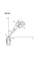
- a collision mitigation device 1 is a device mounted on a vehicle such as a passenger car, detects a target (an object such as another vehicle or a pedestrian) using a radar and a camera image, When there is a possibility of colliding with this target, it has a function of performing control such as braking the host vehicle in order to avoid or reduce the impact at the time of collision.
- the radar axis misalignment (the mounting angle of the millimeter wave radar 2 (the direction of the central axis) is a predetermined angle (parallel to the road surface, and the center of the front surface of the host vehicle).
- the collision mitigation device 1 includes a millimeter wave radar 2, a monocular camera 3, a brake ECU 4, an engine ECU 5, a notification device 6, and a collision mitigation ECU 7.
- the collision mitigation ECU 7 is communicably connected to each of the millimeter wave radar 2, the monocular camera 3, the brake ECU 4, the engine ECU 5, and the notification device 6. Note that the configuration for realizing communication is not particularly limited.
- the millimeter wave radar 2 is a radar for detecting a target (another vehicle, a pedestrian, etc.) using millimeter waves, and a flint grill on the front side of the own vehicle (a vehicle on which the collision mitigation device 1 is mounted). It is attached at the center (tip position).
- the millimeter wave radar 2 transmits the millimeter wave forward while scanning the millimeter wave in a horizontal plane, and transmits the transmission / reception data obtained by receiving the reflected millimeter wave to the collision mitigation ECU 7 as a radar signal. .
- the monocular camera 3 includes one CCD camera and is attached near the mirror (near the center) of the window shield in the passenger compartment of the host vehicle.
- the monocular camera 3 transmits image data captured by the CCD camera to the collision reduction ECU 7 as an image signal.
- the monocular camera 3 has a function of correcting its own axis misalignment, and the front direction of the host vehicle substantially coincides with the axial direction of the monocular camera 3. For this reason, the axial shift of the millimeter wave radar 2 can be detected with reference to the axial direction of the monocular camera 3 (that is, the position of the target obtained from the image).
- the brake ECU 4 is an electronic control device that controls braking of the host vehicle, and includes a CPU, a ROM, a RAM, and the like. Specifically, the brake ECU 4 detects a brake pedal depression amount with respect to a brake ACT (ACT indicates an actuator) that is an actuator for opening and closing a pressure increase control valve and a pressure reduction control valve provided in a brake hydraulic pressure circuit. Control is performed according to the detection value of the sensor. Further, the brake ECU 4 controls the brake ACT so as to increase the braking force of the host vehicle in accordance with an instruction from the collision reduction ECU 7.
- ACT indicates an actuator
- the engine ECU 5 is an electronic control device that controls engine start / stop, fuel injection amount, ignition timing, and the like, and includes a CPU, a ROM, a RAM, and the like. Specifically, the engine ECU 5 controls a throttle ACT, which is an actuator that opens and closes a throttle provided in the intake pipe, according to a detection value of a sensor that detects the amount of depression of the accelerator pedal. Further, the engine ECU 5 controls the throttle ACT so as to reduce the driving force of the internal combustion engine in accordance with an instruction from the collision mitigation ECU 7.
- the alarm device 6 When the alarm device 6 receives an alarm signal from the collision mitigation ECU 7, the alarm device 6 notifies the vehicle driver with sound or light.
- the collision mitigation ECU 7 is an electronic control unit that performs overall control of the collision mitigation apparatus 1 and includes a CPU, a ROM, a RAM, and the like.
- the collision mitigation ECU 7 takes in the radar signal from the millimeter wave radar 2 and the image signal from the monocular camera 3 at regular intervals based on the master clock of the CPU.
- the collision reduction ECU 7 stores a target detection program that is a program for realizing target detection by the collision reduction apparatus 1.
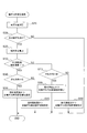
- the collision mitigation processing executed by the collision mitigation ECU 7 in accordance with the target detection program will be described with reference to the flowchart of FIG. Note that the process shown in FIG. 2 is repeatedly executed in a predetermined cycle.
- a target is detected based on a radar signal (detection information by the millimeter wave radar 2) transmitted from the millimeter wave radar 2 (S110).
- the collision mitigation ECU 7 first determines the linear distance from the host vehicle to the target and the horizontal azimuth position of the target (angle position with reference to the front direction of the host vehicle) based on the radar signal. , Is calculated (specified).
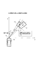
- the position coordinates (X coordinate and Y coordinate) of the target on the XY plane are calculated (specified) as the target detection point Pr on the XY plane.
- the vehicle width direction (lateral direction) of the host vehicle is the X axis
- the vehicle length direction (front direction) of the host vehicle is the Y axis.
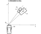
- the tip position of the vehicle (the position where the millimeter wave radar 2 is provided) is set as the reference point Po, and the target detection point Pr represents the relative position with respect to the reference point Po.
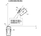
- FIG. 3 is an example of a target positioned in front of the host vehicle and on the right side.
- a relative speed with the target may be calculated.
- the target detected in S110 (the target detected based on the detection information by the millimeter wave radar 2) is referred to as “radar target”.
- an error region 21a centered on the detection point Pr of the radar target calculated in S110 is set (S120).
- the collision mitigation ECU 7 is assumed to be preset based on the characteristics of the millimeter wave radar 2 for each of the X coordinate and the Y coordinate with reference to the X coordinate and the Y coordinate of the detection point Pr of the radar target.
- a region having a width corresponding to the error ( ⁇ ) is set as the error region 21a.
- a target is detected based on an image signal (image captured by the monocular camera 3) transmitted from the monocular camera 3 (S130).
- the collision reduction ECU 7 identifies the target by analyzing the captured image represented by the image signal. For this identification, for example, by executing a matching process using a target model stored in advance, the target is analyzed and identified.
- the collision mitigation ECU 7 specifies the Y coordinate in the XY plane described above based on the vertical position of the target in the captured image, and based on the horizontal position of the target in the captured image, A horizontal azimuth position (an angular position based on the front direction of the host vehicle) is specified.
- the Y coordinate As the target position in the forward direction of the host vehicle is farther (the Y coordinate is larger), the lower end position of the target in the captured image tends to be located on the upper end side of the captured image. For this reason, if the lower end position of the target in the captured image is known, the Y coordinate can be specified. However, such a specifying method has a characteristic that the detection accuracy of the Y coordinate is lowered when the lower end position of the target is not accurately detected.
- the greater the deviation (inclination) in the angular direction of the target relative to the front direction of the vehicle (specifically, the straight line of X 0), the greater the infinite point (FOE: Focus of Expansion) of the monocular camera 3
- FOE Focus of Expansion
- the Y coordinate and the horizontal azimuth position (angular position) of the target on the XY plane are specified as the detection point Pi of the target on the XY plane.
- the target detection point Pi represents a relative position with respect to the reference point Po.
- the target detected in S130 (the target detected based on the image captured by the monocular camera 3) is referred to as an “image target”.
- an error region 22 centered on the detection point Pi of the image target calculated in S130 is set (S140).
- the collision mitigation ECU 7 uses the Y coordinate and the horizontal azimuth position of the detection point Pi as a reference for each of the Y coordinate and the horizontal azimuth position based on the characteristics of the monocular camera 3 set in advance.
- a region having a width is set as an error region 22.
- the axis deviation correction process is a process for correcting the size of the error region 21a when an axis deviation occurs.
- a shaft misalignment amount is calculated (S210). In this process, a calculation for estimating the positional relationship between the radar and the captured image (error between the coordinate system by the radar and the coordinate system by the captured image) is performed.
- the millimeter wave radar 2 detects the arrangement of the roadside object such as a guardrail and the moving direction thereof, and determines the degree of the difference between the inclination of the roadside object arrangement and the moving direction with respect to the traveling direction of the host vehicle. Recognize whether there is any misalignment.
- the relative speed with respect to the target is obtained using the detection result obtained from the millimeter wave radar 2.
- the relative speed is assumed to be a “positive” value, and when the host vehicle approaches the target, the relative speed is set to “negative”. It is defined as a value.
- the relative speed of the target is a “negative” value (S230). If the relative speed of the target is a “negative” value (S230: YES), the direction of the axis deviation is determined (S240). If the direction of the axis deviation is right (S240: YES), an error area is set when the relative speed is “negative” and the axis is displaced to the right (S250).
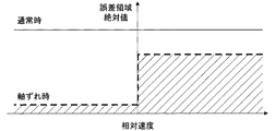
- the error region 21a with respect to the detection point of the millimeter wave radar 2, as shown in FIG. 5, when the axis deviation occurs, the error region 21a is larger than when the axis deviation does not occur (normal time). Set the width narrower. That is, the value of ⁇ shown in FIG. 3 is set smaller.
- the width of the error region 21 a is set narrower than when the relative speed is “positive”. That is, when the relative speed is “negative”, as shown in FIG. 6, the width of the error area 21b is set narrower than the error area 21c when the relative speed shown in FIG. 7 is “positive”.
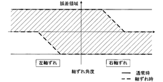
- the error region 21a with respect to the detection point of the millimeter wave radar 2 is corrected not only by the relative speed but also by the direction of the axis deviation and the amount of axis deviation. That is, as shown in FIG. 8, the width of the error region 21a is set to be narrower as the axial deviation increases (away from the center shown in FIG. 8).
- the right side in the vehicle width direction is a “positive” value for both the axis deviation angle and the error region. That is, when the axial deviation to the right increases, the left portion of the error region 21a is not narrowed, whereas the right portion of the error region 21a is corrected narrowly. On the other hand, when the axial deviation to the left increases, the right portion of the error region 21a is not narrowed, whereas the left portion of the error region 21a is corrected narrowly.
- the corrected error region 22d has a left-side width of ⁇ , whereas The width of this portion is corrected to ⁇ , for example.
- a map for correcting the width of the error region 21a according to the relative speed shown in FIG. 5 and a map for correcting the width of the error region 21a according to the axis deviation direction and the axis deviation amount shown in FIG. Is applied to the error region 21a to obtain a corrected error region 21a.
- an error region is set using a map similar to S250.
- S160 If it is determined in S160 that there is an overlapping part (S160: YES), it is determined that the radar target and the image target are the same target (S170). In this case, a position specified by the Y coordinate of the detection point Pr of the radar target and the horizontal azimuth position of the image target is set as the position of the target (target determined to be the same) on the XY plane.
- the reliability (the reliability of the determination result) that the radar target and the image target are the same target is calculated (S180).
- the angle difference between the horizontal azimuth position of the radar target detection point Pr and the horizontal azimuth position of the image target detection point Pi is calculated as the reliability. That is, the smaller the angle difference, the higher the reliability.
- the collision reduction ECU 7 When it is determined in S160 that there is no overlapping portion (S160: NO), the collision reduction ECU 7 does not determine that the radar target and the image target are the same target (different targets). Determined). In this case, the process proceeds to S190.
- collision mitigation control is performed according to the detected position and reliability of the target (S190). For example, when there is a possibility of collision with a target, an alarm signal is transmitted to the notification device 6 to notify the driver. When there is a high possibility of collision with the target, the engine ECU 5 is instructed to decrease the driving force of the internal combustion engine, and the brake ECU 4 is instructed to increase the braking force of the host vehicle.
- the collision mitigation ECU 7 varies the control mode according to the reliability. For example, when the reliability is high, the control timing is advanced compared to when the reliability is low.
- the collision mitigation ECU 7 corresponds to the target detection device referred to in the present invention.
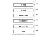
- FIG. 1B shows functional blocks representing the functions of the collision mitigation ECU 7 realized by a processor, software, or a combination thereof.
- the collision mitigation ECU 7 includes functional blocks such as a first specifying unit 701, a second specifying unit 702, an axis misalignment acquisition unit 703, a relative speed acquisition unit 704, a region size change unit 705, and a determination unit 706.
- the first specifying unit 701 executes the processes of steps S110 to S120.
- the second specifying unit 702 executes the processes of steps S130 to S140.
- the axis deviation presence / absence acquisition unit 703 executes the process of step S210.
- the relative speed acquisition unit 704 executes the process of step S225.
- the area size changing unit 705 executes the processes of steps S230 to S330.
- the determination unit 706 executes steps S160 to S170.
- the collision mitigation ECU 7 acquires the presence / absence of an axis deviation indicating the deviation of the reference direction of the millimeter wave radar 2 and the axis of the monocular camera 3 from the reference direction, and there is an axis deviation.
- the size of the first area is changed. Furthermore, on the XY plane, it is determined that the first target and the second target are the same target on the condition that there is an overlapping portion in the first area and the second area.
- a collision mitigation device 1 it is possible to change whether or not there is an overlapping portion by changing the size of the first region when there is an axis deviation. The determination of whether or not can be performed satisfactorily.
- the collision mitigation ECU 7 narrows the first region when there is an axis deviation. In other words, when there is an axis misalignment, there is a higher possibility that a non-identical target will be misrecognized as the same target. Therefore, by narrowing the first area, a non-identical target is the same target. It is difficult to be recognized.
- the collision mitigation ECU 7 also has information on which direction the left and right of the reference orientation of the monocular camera 3 is deviated from the reference orientation of the millimeter wave radar 2 when an axis deviation occurs. When there is an axis deviation, the area in the direction in which the axis deviation occurs in the first area is narrowed.
- the collision mitigation ECU 7 obtains the difference of the vehicle speed with respect to the speed of the first target or the second target as a relative speed, and when the relative speed is a negative value, The first region is made narrower than when the speed is a positive value.
- the first area is narrowed when the host vehicle is approaching the target whose relative speed is a negative value, so that different targets are the same target. It can be hard to be mistakenly recognized as being. Therefore, when performing the collision mitigation process, it is possible to suppress malfunction of vehicle control due to erroneous recognition that different targets are the same target.
- the collision mitigation ECU 7 sets an area within a certain angle range including an orientation relative to the reference point of the first target as the width of the first area, and changes the size of the first area. Only the width of the first area is changed.
- various forms such as a system including the collision mitigation device 1 as a constituent element, a program for causing a computer to function as the collision mitigation device 1, a medium on which the program is recorded, and a collision mitigation method
- the present invention can be realized.
- the map for correcting the width of the error area 21a according to the relative speed and the map for correcting the width of the error area 21a according to the axis deviation direction and the axis deviation amount are applied in combination. Either one of them may be applied to obtain the corrected error region 21a.
Abstract
物標検出装置(7)において、第1特定部(701、S110~S120)は、ミリ波レーダによる検出情報に基づいて検出された第1の物標について、XY平面における基準点に対する第1の物標の相対位置を表す検出点である第1の検出点を含む第1領域を特定し、第2特定部(702、S130~S140)は、撮像画像に基づいて検出された第2の物標について、XY平面における基準点に対する第2の物標の相対位置を表す検出点である第2の検出点を含む第2領域を特定する。領域サイズ変更部(705、S230~S330)は、ミリ波レーダ2の軸の基準方位に対するずれを表す軸ずれの有無を取得し、軸ずれがある場合に第1領域のサイズを変更する。判定部(706、S160~S170)は、第1領域と第2領域とに重複部が存在することを条件として、各物標が同一の物標であると判定する。
Description
本出願は、2014年9月24日に出願された日本出願番号2014-193889号に基づくもので、ここにその記載内容を援用する。
本発明は、レーダおよびカメラを用いて物標を検出する技術に関する。
例えば車両の衝突回避システムでは、他の車両や歩行者等の物標を精度よく検出することが求められる。そこで、レーダおよびカメラを用いて物標を検出する構成が提案されている(特許文献1参照)。具体的には、特許文献1に記載の構成では、ミリ波レーダおよび単眼カメラによりそれぞれ独立して物標が検出され、それら物標の位置関係が判断基準を満たしている場合に、それらの物標が同一物標であると判定される。
しかしながら、上記システムでは、センサの取り付け角度が予め決められた角度に対して水平方向或いは垂直方向に軸がずれる、いわゆる軸ずれが発生することがあり、この軸ずれの補正が不十分であると、同一物標であるか否かを判定する際の精度が悪くなるという問題点があった。
そこで、このような問題点を鑑み、レーダおよびカメラを用いて物標を検出する物標検出装置であって、軸ずれが生じたときであっても同一物標であるか否かの判定をより正確に実施することができる物標検出装置を提供することを本発明の目的とする。
本発明の一態様による物標検出装置において、第1特定部は、レーダによる検出情報に基づいて検出された第1の物標について、車両を基準として、車両の車幅方向をX軸、車両の車長方向をY軸、としたXY平面における基準点に対する第1の物標の相対位置を表す検出点である第1の検出点を含む第1領域を特定する。また、第2特定部は、単眼カメラによる撮像画像に基づいて検出された第2の物標について、XY平面における基準点に対する第2の物標の相対位置を表す検出点である第2の検出点を含む第2領域を特定する。
そして、軸ずれ有無取得部は、レーダの軸の基準方位に対するずれを表す軸ずれの有無を取得し、領域サイズ変更部は、軸ずれがある場合に第1領域のサイズを変更する。さらに、判定部は、XY平面において、第1領域と第2領域とに重複部が存在することを条件として、第1の物標と第2の物標とが同一の物標であると判定する。
このような物標検出装置によれば、軸ずれがある場合に第1領域のサイズを変更することで、重複部が存在するか否かを変化させることができるので、同一物標であるか否かの判定をより正確に実施することができる。
本発明の上述およびその他の目的、特徴、および利点は、好ましい実施形態に関する以下の詳細な説明を添付の図面と共に読めば、容易に明らかになり、十分に理解できるであろう。
以下、本発明の実施形態を、添付図面を参照しながら、より詳細に説明する。しかし、本発明は、多くの異なる形態で実施されてもよく、本明細書で説明される実施形態に限定されると解釈されるべきではない。むしろ、これらの実施形態は、この発明の開示を徹底的でかつ完全にし、本発明の範囲を当業者に完全に伝えるために、提供される。尚、類似の符号は、図面全体にわたって類似の構成要素を示す。
(構成)
本発明の実施の一形態による衝突軽減装置1は、乗用車等の車両に搭載された装置であって、レーダおよびカメラ画像を用いて物標(他車両や歩行者等の物体)を検出し、この物標と衝突する虞がある場合に、衝突を回避または衝突する際の衝撃を軽減するために、自車両を制動する等の制御を行う機能を有する。特に、本実施形態の衝突軽減装置1においては、レーダの軸ずれ(ミリ波レーダ2の取り付け角度(中心軸の方位)が予め決められた角度(路面に平行であり、自車両の前面の中央と背面の中央とを通る直線のうちの前方方向である正面方向)に対して水平方向或いは垂直方向にずれる現象)が生じている場合に、異なる物標を1つの物標(同一物標)であると誤認識しにくくするための機能を備えている。
本発明の実施の一形態による衝突軽減装置1は、乗用車等の車両に搭載された装置であって、レーダおよびカメラ画像を用いて物標(他車両や歩行者等の物体)を検出し、この物標と衝突する虞がある場合に、衝突を回避または衝突する際の衝撃を軽減するために、自車両を制動する等の制御を行う機能を有する。特に、本実施形態の衝突軽減装置1においては、レーダの軸ずれ(ミリ波レーダ2の取り付け角度(中心軸の方位)が予め決められた角度(路面に平行であり、自車両の前面の中央と背面の中央とを通る直線のうちの前方方向である正面方向)に対して水平方向或いは垂直方向にずれる現象)が生じている場合に、異なる物標を1つの物標(同一物標)であると誤認識しにくくするための機能を備えている。
衝突軽減装置1は、図1Aに示すように、ミリ波レーダ2と、単眼カメラ3と、ブレーキECU4と、エンジンECU5と、報知装置6と、衝突軽減ECU7と、を備える。衝突軽減装置1において、衝突軽減ECU7は、ミリ波レーダ2、単眼カメラ3、ブレーキECU4、エンジンECU5および報知装置6のそれぞれと通信可能に接続されている。なお、通信を実現するための構成は、特に限定されない。
ミリ波レーダ2は、ミリ波を利用して物標(他車両や歩行者等)を検出するためのレーダであって、自車両(衝突軽減装置1が搭載された車両)の前側のフリントグリルの中央(先端位置)に取り付けられている。ミリ波レーダ2は、ミリ波を水平面内でスキャンしながら自車両から前方に向けて送信し、反射してきたミリ波を受信することによって得られる送受信データを、レーダ信号として衝突軽減ECU7へ送信する。
単眼カメラ3は、1台のCCDカメラを備え、自車両の車室内のウィンドウシールドのミラー付近(中央付近)に取り付けられている。単眼カメラ3は、CCDカメラで撮像した画像のデータを、画像信号として衝突軽減ECU7へ送信する。なお、単眼カメラ3は自身の軸ずれを補正する機能を備えており、自車両の正面の方向は、単眼カメラ3の軸方向と概ね一致する。このため、単眼カメラ3の軸方向(つまり、画像にて得られた物標の位置)を基準としてミリ波レーダ2の軸ずれを検出することができる。
ブレーキECU4は、自車両の制動を制御する電子制御装置であって、CPU、ROM、RAMなどを備える。具体的には、ブレーキECU4は、ブレーキ液圧回路に設けられた増圧制御弁および減圧制御弁を開閉するアクチュエータであるブレーキACT(ACTはActuatorを示す)を、ブレーキペダルの踏込量を検出するセンサの検出値に応じて制御する。また、ブレーキECU4は、衝突軽減ECU7からの指示に従い、自車両の制動力を増加させるようにブレーキACTを制御する。
エンジンECU5は、エンジンの始動/停止、燃料噴射量、点火時期等を制御する電子制御装置であって、CPU、ROM、RAMなどを備える。具体的には、エンジンECU5は、吸気管に設けられたスロットルを開閉するアクチュエータであるスロットルACTを、アクセルペダルの踏込量を検出するセンサの検出値に応じて制御する。また、エンジンECU5は、衝突軽減ECU7からの指示に従い、内燃機関の駆動力を減少させるようにスロットルACTを制御する。
報知装置6は、衝突軽減ECU7から警報信号を受信すると、音や光などで車両の運転者に対する報知を行う。
衝突軽減ECU7は、衝突軽減装置1を統括制御する電子制御装置であって、CPU、ROM、RAMなどを備える。衝突軽減ECU7は、CPUのマスタクロックに基づく一定時間ごとに、ミリ波レーダ2からのレーダ信号および単眼カメラ3からの画像信号を取り入れる。
(処理)
次に、衝突軽減装置1による物標検出方法について説明する。衝突軽減ECU7には、衝突軽減装置1による物標検出を実現するためのプログラムである物標検出プログラムが記憶されている。以下、物標検出プログラムに従い衝突軽減ECU7が実行する衝突軽減処理について、図2のフローチャートを用いて説明する。なお、図2に示す処理は、所定サイクルで繰り返し実行される。
次に、衝突軽減装置1による物標検出方法について説明する。衝突軽減ECU7には、衝突軽減装置1による物標検出を実現するためのプログラムである物標検出プログラムが記憶されている。以下、物標検出プログラムに従い衝突軽減ECU7が実行する衝突軽減処理について、図2のフローチャートを用いて説明する。なお、図2に示す処理は、所定サイクルで繰り返し実行される。
衝突軽減処理では、図2に示すように、まず、ミリ波レーダ2から送信されるレーダ信号(ミリ波レーダ2による検出情報)に基づいて、物標を検出する(S110)。具体的には、衝突軽減ECU7は、レーダ信号に基づいて、まず、自車両から物標までの直線距離と、その物標の水平方位位置(自車両の前方方向を基準とする角度位置)と、を算出(特定)する。
そして、これらの算出値に基づき、図3に示すように、XY平面における物標の位置座標(X座標およびY座標)を、XY平面における物標の検出点Prとして算出(特定)する。このXY平面は、自車両の車幅方向(横方向)をX軸、自車両の車長方向(前方方向)をY軸、としたものである。
また、このXY平面では、自車両の先端位置(ミリ波レーダ2が設けられた位置)が基準点Poとして設定され、物標の検出点Prは基準点Poに対する相対位置を表す。なお、図3は、自車両の前方かつ右寄りに位置する物標の例である。また、このS110において、物標の検出点Prに加え、物標との相対速度等を算出してもよい。また、以下の説明では、S110で検出した物標(ミリ波レーダ2による検出情報に基づいて検出した物標)を「レーダ物標」という。
続いて、図3に示すように、S110で算出したレーダ物標の検出点Prを中心とする誤差領域21aを設定する(S120)。具体的には、衝突軽減ECU7は、レーダ物標の検出点PrのX座標およびY座標を基準として、X座標およびY座標のそれぞれについて、ミリ波レーダ2の特性に基づきあらかじめ設定されている想定誤差分(Δθ)の幅を持たせた領域を、誤差領域21aとして設定する。
続いて、単眼カメラ3から送信される画像信号(単眼カメラ3による撮像画像)に基づいて、物標を検出する(S130)。具体的には、衝突軽減ECU7は、画像信号の表す撮像画像を解析して物標を識別する。この識別は、例えば、予め記憶されている物標モデルを用いたマッチング処理を実行することによって、解析して物標を識別する。
物標モデルは、物標の種類(車両、歩行者等)ごとに用意されているため、物標の種類も特定される。そして、衝突軽減ECU7は、撮像画像における物標の上下方向の位置に基づいて、前述したXY平面におけるY座標を特定し、撮像画像における物標の左右方向の位置に基づいて、その物標の水平方位位置(自車両の前方方向を基準とする角度位置)を特定する。
すなわち、自車両の前方方向における物標の位置が遠い(Y座標が大きい)ほど、撮像画像における物標の下端位置は、撮像画像の上端側に位置する傾向がある。このため、撮像画像における物標の下端位置が分れば、Y座標を特定することができる。ただし、このような特定方法は、物標の下端位置が正確に検出されない場合に、Y座標の検出精度が下がるという特性がある。
また、自車両の前方方向(詳細にはX=0の直線)を基準とする物標の角度方向のずれ(傾き)が大きいほど、単眼カメラ3の無限遠点(FOE:Focus of Expansion)を基準とするその物標の左右方向へのずれが大きくなる傾向にある。このため、X=0の直線を基準としたときのPoおよび物標を通る直線の角度、並びに物標の中心を通る鉛直線までの距離に基づいて、物標の水平方位位置を特定することができる。
つまり、このS130においては、図3に示すように、XY平面における物標のY座標および水平方位位置(角度位置)を、XY平面における物標の検出点Piとして特定する。物標の検出点Piは基準点Poに対する相対位置を表す。なお、以下の説明では、S130で検出した物標(単眼カメラ3による撮像画像に基づいて検出した物標)を「画像物標」という。
続いて、図3に示すように、S130で算出した画像物標の検出点Piを中心とする誤差領域22を設定する(S140)。具体的には、衝突軽減ECU7は、検出点PiのY座標および水平方位位置を基準として、Y座標および水平方位位置のそれぞれについて、単眼カメラ3の特性に基づきあらかじめ設定されている想定誤差分の幅を持たせた領域を、誤差領域22として設定する。
続いて、軸ずれ時補正処理を実施する(S150)。軸ずれ時補正処理は、軸ずれが生じたときに誤差領域21aのサイズを補正する処理である。
軸ずれ時補正処理は、図4に示すように、まず、軸ずれ量を演算する(S210)。この処理では、レーダと撮像画像と間の位置関係(レーダによる座標系と撮像画像による座標系との誤差)を推定するための演算を行う。この処理では、例えば、ミリ波レーダ2によってガードレール等の路側物の配置とその移動方向を検出し、自車両の進行方向に対する路側物の配置の傾きや移動方向の相違量を求めることによってどの程度の軸ずれが生じているかを認識する。
軸ずれ時補正処理は、図4に示すように、まず、軸ずれ量を演算する(S210)。この処理では、レーダと撮像画像と間の位置関係(レーダによる座標系と撮像画像による座標系との誤差)を推定するための演算を行う。この処理では、例えば、ミリ波レーダ2によってガードレール等の路側物の配置とその移動方向を検出し、自車両の進行方向に対する路側物の配置の傾きや移動方向の相違量を求めることによってどの程度の軸ずれが生じているかを認識する。
続いて、水平方向の軸ずれが生じているか否かを判定する(S220)。この処理では、軸ずれ量が閾値(例えば1deg程度)以上である場合に、軸ずれが生じていると判定する。
水平方向の軸ずれが生じていれなければ(S220:NO)、軸ずれ時補正処理を終了する。また、水平方向の軸ずれが生じていれば(S220:YES)、物標との相対速度を算出する(S225)。
この処理では、ミリ波レーダ2から得られた検出結果を利用して物標との相対速度を求める。なお、本実施形態においては、自車両と物標とが遠ざかる際に、相対速度が「正」の値であるものとし、自車両が物標に接近する際に、相対速度が「負」の値であるものと定義する。
続いて、物標の相対速度が「負」の値であるか否かを判定する(S230)。物標の相対速度が「負」の値であれば(S230:YES)、軸ずれの方向について判定を行う(S240)。軸ずれの方向が右であれば(S240:YES)、相対速度が「負」かつ右への軸ずれ時の誤差領域を設定する(S250)。
ここで、ミリ波レーダ2の検出点に対する誤差領域21aについては、図5に示すように、軸ずれが生じている場合に、軸ずれが生じていないとき(通常時)よりも誤差領域21aの幅を狭く設定する。つまり、図3に示すところのΔθの値をより小さく設定することになる。
特に、図5に示すように、軸ずれが生じているときにおいて、相対速度が「負」の場合には、相対速度が「正」の場合よりも誤差領域21aの幅を狭く設定する。つまり、相対速度が「負」の場合には、図7に示す相対速度が「正」の場合の誤差領域21cに対して、図6に示すように、より誤差領域21bの幅が狭く設定されることが分かる。
また、ミリ波レーダ2の検出点に対する誤差領域21aは、相対速度だけでなく、軸ずれの方向および軸ずれ量によっても補正される。すなわち、図8に示すように、軸ずれが大きくなるにつれて(図8に示す中心から離れるにつれて)誤差領域21aの幅が狭く設定される。
なお、図8においては、軸ずれ角度および誤差領域ともに、車幅方向の右側を「正」の値としている。つまり、右側への軸ずれが大きくなると、誤差領域21aの左側の部分は狭くされないのに対して、誤差領域21aの右側の部分が狭く補正される。また反対に、左側への軸ずれが大きくなると、誤差領域21aの右側の部分は狭くされないのに対して、誤差領域21aの左側の部分が狭く補正される。
より具体的には、例えば図9に示すように、右側への軸ずれ量をαとすると、補正後の誤差領域22dは、左側の部分の幅がΔθのままであるのに対して、右側の部分の幅は、例えば、Δθ-αと補正される。
このように、S250では、図5に示す相対速度に応じて誤差領域21aの幅を補正するマップと、図8に示す軸ずれ方向および軸ずれ量に応じて誤差領域21aの幅を補正するマップとを組み合わせて決定される補正量を誤差領域21aに対して適用することで補正後の誤差領域21aを得る。なお、後述するS260、S320、S330においても、S250と同様のマップを用いて誤差領域を設定する。
具体的には、S240の処理において、軸ずれの方向が左であれば(S240:NO)、相対速度が「負」かつ左への軸ずれ時の誤差領域を設定する(S260)。また、S230の処理にて、物標の相対速度が0または「正」の値であれば(S230:NO)、軸ずれの方向について判定を行う(S310)。
軸ずれの方向が右であれば(S310:YES)、相対速度が「正」かつ右への軸ずれ時の誤差領域を設定する(S320)。また、軸ずれの方向が左であれば(S310:NO)、相対速度が「正」かつ左への軸ずれ時の誤差領域を設定する(S330)。
このような処理が終了すると、軸ずれ時補正処理が終了する。続いて、図2に戻り、XY平面において、レーダの誤差領域21aと誤差領域22とに重複部(重なり領域)が存在するか否かを判定する(S160)。
このS160で重複部が存在すると判定した場合(S160:YES)、レーダ物標と画像物標とが同一の物標であると判定する(S170)。この場合、レーダ物標の検出点PrのY座標と画像物標の水平方位位置とで特定される位置を、XY平面におけるその物標(同一と判定された物標)の位置とする。
続いて、レーダ物標と画像物標とが同一の物標であることの信頼度(判定結果の信頼度)を算出する(S180)。本実施形態では、レーダ物標の検出点Prの水平方位位置と画像物標の検出点Piの水平方位位置との角度差を、信頼度として算出する。つまり、角度差が小さいほど、高い信頼度を表す。
なお、前述したS160で重複部が存在しないと判定した場合(S160:NO)、衝突軽減ECU7は、レーダ物標と画像物標とが同一の物標であると判定しない(異なる物標であると判定する)。この場合、S190に移行する。
続いて、検出した物標の位置および信頼度に応じた衝突軽減制御を行う(S190)。例えば、物標に衝突する可能性がある場合に、報知装置6へ警報信号を送信して、運転者に対する報知を行わせる。また、物標に衝突する可能性が高い場合には、エンジンECU5へ内燃機関の駆動力を減少させる指示を行い、また、ブレーキECU4へ自車両の制動力を増加させる指示を行う。
そして、衝突軽減ECU7は、信頼度に応じて制御態様を異ならせる。例えば、信頼度が高い場合には、信頼度が低い場合と比較して、制御のタイミングを早くする。
上記実施形態において衝突軽減ECU7は本発明でいう物標検出装置に相当する。図1Bは、プロセッサ、ソフトウェア、またはこれらの組み合わせによって実現される衝突軽減ECU7の機能を表す機能ブロックを示している。衝突軽減ECU7は、第1特定部701、第2特定部702、軸ずれ有無取得部703、相対速度取得部704、領域サイズ変更部705、及び判定部706といった機能ブロックを有する。第1特定部701は、ステップS110~S120の処理を実行する。第2特定部702は、ステップS130~S140の処理を実行する。軸ずれ有無取得部703は、ステップS210の処理を実行する。相対速度取得部704は、ステップS225の処理を実行する。領域サイズ変更部705は、ステップS230~S330の処理を実行する。そして判定部706は、ステップS160~S170の処理を実行する。
以上のように詳述した衝突軽減装置1において衝突軽減ECU7は、ミリ波レーダ2の基準方位と単眼カメラ3の軸の基準方位に対するずれを表す軸ずれの有無を取得し、軸ずれがある場合に第1領域のサイズを変更する。さらに、XY平面において、第1領域と第2領域とに重複部が存在することを条件として、第1の物標と第2の物標とが同一の物標であると判定する。
このような衝突軽減装置1によれば、軸ずれがある場合に第1領域のサイズを変更することで、重複部が存在するか否かを変化させることができるので、同一物標であるか否かの判定を良好に実施することができる。
また、衝突軽減装置1において衝突軽減ECU7は、軸ずれがある場合に第1領域をより狭くする。すなわち、軸ずれがある場合には同一でない物標が同一の物標であると誤認識される可能性が高まるため、第1領域を狭くすることで同一でない物標が同一の物標であると認識されにくくする。
従って、このような衝突軽減装置1によれば、同一物標であるか否かの判定を良好に実施することができる。
また、衝突軽減装置1において衝突軽減ECU7は、軸ずれが生じた際に、単眼カメラ3の基準方位がミリ波レーダ2の基準方位に対して左右の何れの方向にずれているかについての情報も取得し、軸ずれがある場合に、第1領域のうちの軸ずれが生じた方向における領域を狭くする。
また、衝突軽減装置1において衝突軽減ECU7は、軸ずれが生じた際に、単眼カメラ3の基準方位がミリ波レーダ2の基準方位に対して左右の何れの方向にずれているかについての情報も取得し、軸ずれがある場合に、第1領域のうちの軸ずれが生じた方向における領域を狭くする。
すなわち、軸ずれが生じた場合、軸ずれが生じた方向に存在する異なる物標が同一の物標であると誤認識される可能性が高くなるため、第1領域のうちの軸ずれが生じた方向における領域を狭くする。従って、このような衝突軽減装置1によれば、同一物標であるか否かの判定を良好に実施することができる。
また、衝突軽減装置1において衝突軽減ECU7は、第1の物標または第2の物標の速度に対する車両の速度の差分を相対速度として取得し、相対速度が負の値である際に、相対速度が正の値である際と比較して第1領域をより狭くする。
このような衝突軽減装置1によれば、相対速度が負の値となる、自車両が物標に接近しているときには、第1領域をより狭くするので、異なる物標が同一の物標であると誤認識されにくくすることができる。よって、衝突軽減処理を実施する際に、異なる物標が同一の物標であると誤認識されることによる車両制御の誤作動を抑制することができる。
また、衝突軽減装置1において衝突軽減ECU7は、第1の物標の基準点に対する方位を含むある角度範囲内の領域を第1領域の幅として設定し、第1領域のサイズを変更する際に、第1領域の幅だけを変更する。
このような衝突軽減装置1によれば、第1領域のうちの軸ずれの影響が生じやすい方向である幅だけを変更するので、奥行き方向については軸ずれに伴う同一判定結果が変化しないようにすることができる。
(その他の実施形態)
本発明は、上記の実施形態によって何ら限定して解釈されない。また、上記の実施形態の説明で用いる符号を特許請求の範囲にも適宜使用しているが、各請求項に係る発明の理解を容易にする目的で使用しており、各請求項に係る発明の技術的範囲を限定する意図ではない。上記実施形態における1つの構成要素が有する機能を複数の構成要素として分散させたり、複数の構成要素が有する機能を1つの構成要素に統合させたりしてもよい。また、上記実施形態の構成の少なくとも一部を、同様の機能を有する公知の構成に置き換えてもよい。また、上記実施形態の構成の一部を省略してもよい。また、上記実施形態の構成の少なくとも一部を、他の上記実施形態の構成に対して付加又は置換してもよい。なお、特許請求の範囲に記載した文言のみによって特定される技術思想に含まれるあらゆる態様が本発明の実施形態である。
本発明は、上記の実施形態によって何ら限定して解釈されない。また、上記の実施形態の説明で用いる符号を特許請求の範囲にも適宜使用しているが、各請求項に係る発明の理解を容易にする目的で使用しており、各請求項に係る発明の技術的範囲を限定する意図ではない。上記実施形態における1つの構成要素が有する機能を複数の構成要素として分散させたり、複数の構成要素が有する機能を1つの構成要素に統合させたりしてもよい。また、上記実施形態の構成の少なくとも一部を、同様の機能を有する公知の構成に置き換えてもよい。また、上記実施形態の構成の一部を省略してもよい。また、上記実施形態の構成の少なくとも一部を、他の上記実施形態の構成に対して付加又は置換してもよい。なお、特許請求の範囲に記載した文言のみによって特定される技術思想に含まれるあらゆる態様が本発明の実施形態である。
上述した衝突軽減装置1の他、当該衝突軽減装置1を構成要素とするシステム、当該衝突軽減装置1としてコンピュータを機能させるためのプログラム、このプログラムを記録した媒体、衝突軽減方法など、種々の形態で本発明を実現することもできる。
例えば、上記実施形態において、相対速度に応じて誤差領域21aの幅を補正するマップと、軸ずれ方向および軸ずれ量に応じて誤差領域21aの幅を補正するマップとを組み合わせて適用したが、何れか一方を適用して補正後の誤差領域21aを得るようにしてもよい。
Claims (5)
- 車両に搭載される物標検出装置(7)であって、
レーダ(2)による検出情報に基づいて検出された第1の物標について、前記車両を基準として、前記車両の車幅方向をX軸、前記車両の車長方向をY軸、としたXY平面における基準点に対する前記第1の物標の相対位置を表す検出点である第1の検出点を含む第1領域を特定する第1特定部(701、S110~S120)と、
単眼カメラ(3)による撮像画像に基づいて検出された第2の物標について、前記XY平面における前記基準点に対する前記第2の物標の相対位置を表す検出点である第2の検出点を含む第2領域を特定する第2特定部(702、S130~S140)と、
前記レーダの軸の基準方位に対するずれを表す軸ずれの有無を取得する軸ずれ有無取得部(703、S210)と、
前記軸ずれがある場合に前記第1領域のサイズを変更する領域サイズ変更部(705、S230~S330)と、
前記XY平面において、前記第1領域と前記第2領域とに重複部が存在することを条件として、前記第1の物標と前記第2の物標とが同一の物標であると判定する判定部(706、S160~S170)と、
を備えたことを特徴とする物標検出装置(7)。 - 請求項1に記載の物標検出装置(7)において、
前記領域サイズ変更部(705、S230~S330)は、前記軸ずれがある場合に前記第1領域をより狭くすること
を特徴とする物標検出装置(7)。 - 請求項2に記載の物標検出装置(7)において、
前記軸ずれ有無取得部(703、S210)は、前記軸ずれが生じた際に、前記単眼カメラの基準方位が前記レーダの基準方位に対して左右の何れの方向にずれているかについての情報も取得し、
前記領域サイズ変更部(705、S230~S330)は、前記軸ずれがある場合に、前記第1領域のうちの軸ずれが生じた方向における領域を狭くすること
を特徴とする物標検出装置(7)。 - 請求項2または請求項3に記載の物標検出装置(7)において、
前記第1の物標または前記第2の物標の速度に対する前記車両の速度の差分を相対速度として取得する相対速度取得部(704、S225)、を備え、
前記領域サイズ変更部(705、S230~S330)は、前記相対速度が負の値である際に、前記相対速度が正の値である際と比較して前記第1領域をより狭くすること
を特徴とする物標検出装置(7)。 - 請求項1~請求項4の何れか1項に記載の物標検出装置(7)において、
前記第1特定部(701、S110~S120)は、前記第1の物標の前記基準点に対する方位を含むある角度範囲内の領域を前記第1領域の幅として設定し、
前記領域サイズ変更部(705、S230~S330)は、前記第1領域のサイズを変更する際に、前記第1領域の幅だけを変更すること
を特徴とする物標検出装置(7)。
Priority Applications (1)
| Application Number | Priority Date | Filing Date | Title |
|---|---|---|---|
| US15/513,522 US9945927B2 (en) | 2014-09-24 | 2015-09-10 | Object detection apparatus |
Applications Claiming Priority (2)
| Application Number | Priority Date | Filing Date | Title |
|---|---|---|---|
| JP2014-193889 | 2014-09-24 | ||
| JP2014193889A JP6394227B2 (ja) | 2014-09-24 | 2014-09-24 | 物体検出装置 |
Publications (1)
| Publication Number | Publication Date |
|---|---|
| WO2016047457A1 true WO2016047457A1 (ja) | 2016-03-31 |
Family
ID=55580984
Family Applications (1)
| Application Number | Title | Priority Date | Filing Date |
|---|---|---|---|
| PCT/JP2015/075746 WO2016047457A1 (ja) | 2014-09-24 | 2015-09-10 | 物標検出装置 |
Country Status (3)
| Country | Link |
|---|---|
| US (1) | US9945927B2 (ja) |
| JP (1) | JP6394227B2 (ja) |
| WO (1) | WO2016047457A1 (ja) |
Families Citing this family (10)
| Publication number | Priority date | Publication date | Assignee | Title |
|---|---|---|---|---|
| JP6493196B2 (ja) * | 2015-12-17 | 2019-04-03 | 株式会社デンソー | 制御装置、制御方法 |
| JP6881175B2 (ja) * | 2017-09-13 | 2021-06-02 | トヨタ自動車株式会社 | 運転支援装置、および、運転支援装置の制御方法 |
| CN108831189A (zh) * | 2018-06-07 | 2018-11-16 | 合肥中科自动控制系统有限公司 | 一种基于毫米波雷达防撞的智能预警方法 |
| US20220404488A1 (en) * | 2018-10-01 | 2022-12-22 | Kpit Technologies Limited | Perception sensors based fusion system for vehicle control and method thereof |
| KR20200040391A (ko) * | 2018-10-10 | 2020-04-20 | 주식회사 만도 | 차량용 레이더의 보완 장치 및 방법 |
| CN109466547A (zh) * | 2019-01-02 | 2019-03-15 | 华域汽车系统股份有限公司 | 一种完全基于雷达含自动泊车功能的智能驾驶系统及方法 |
| JP7128449B2 (ja) * | 2019-04-18 | 2022-08-31 | トヨタ自動車株式会社 | 運転支援装置及びその運転支援装置の調整方法 |
| US11557061B2 (en) * | 2019-06-28 | 2023-01-17 | GM Cruise Holdings LLC. | Extrinsic calibration of multiple vehicle sensors using combined target detectable by multiple vehicle sensors |
| CN112799055A (zh) * | 2020-12-28 | 2021-05-14 | 深圳承泰科技有限公司 | 一种探测被测车辆的方法、装置以及电子设备 |
| JP2022150929A (ja) * | 2021-03-26 | 2022-10-07 | 本田技研工業株式会社 | 軸ずれ推定装置 |
Citations (4)
| Publication number | Priority date | Publication date | Assignee | Title |
|---|---|---|---|---|
| JP2010249613A (ja) * | 2009-04-14 | 2010-11-04 | Toyota Motor Corp | 障害物認識装置及び車両制御装置 |
| JP2011220732A (ja) * | 2010-04-06 | 2011-11-04 | Honda Motor Co Ltd | 車両の周辺監視装置 |
| JP2012068216A (ja) * | 2010-09-27 | 2012-04-05 | Mazda Motor Corp | センサの方位ずれ検出装置 |
| JP2014122873A (ja) * | 2012-11-22 | 2014-07-03 | Denso Corp | 物標検出装置 |
Family Cites Families (4)
| Publication number | Priority date | Publication date | Assignee | Title |
|---|---|---|---|---|
| JP3931891B2 (ja) * | 2004-07-05 | 2007-06-20 | 日産自動車株式会社 | 車載用画像処理装置 |
| JP2011068216A (ja) * | 2009-09-24 | 2011-04-07 | Honda Motor Co Ltd | 全方向移動車両の制御装置 |
| DE102010002105A1 (de) * | 2010-02-18 | 2011-08-18 | Robert Bosch GmbH, 70469 | Verfahren zur Unterstützung eines Fahrers eines Fahrzeugs bei einem Fahrmanöver |
| JP6019959B2 (ja) * | 2012-09-06 | 2016-11-02 | 富士通株式会社 | 物体検出装置、物体検出プログラムおよび車両 |
-
2014
- 2014-09-24 JP JP2014193889A patent/JP6394227B2/ja active Active
-
2015
- 2015-09-10 US US15/513,522 patent/US9945927B2/en active Active
- 2015-09-10 WO PCT/JP2015/075746 patent/WO2016047457A1/ja active Application Filing
Patent Citations (4)
| Publication number | Priority date | Publication date | Assignee | Title |
|---|---|---|---|---|
| JP2010249613A (ja) * | 2009-04-14 | 2010-11-04 | Toyota Motor Corp | 障害物認識装置及び車両制御装置 |
| JP2011220732A (ja) * | 2010-04-06 | 2011-11-04 | Honda Motor Co Ltd | 車両の周辺監視装置 |
| JP2012068216A (ja) * | 2010-09-27 | 2012-04-05 | Mazda Motor Corp | センサの方位ずれ検出装置 |
| JP2014122873A (ja) * | 2012-11-22 | 2014-07-03 | Denso Corp | 物標検出装置 |
Also Published As
| Publication number | Publication date |
|---|---|
| US20170315207A1 (en) | 2017-11-02 |
| JP6394227B2 (ja) | 2018-09-26 |
| US9945927B2 (en) | 2018-04-17 |
| JP2016066179A (ja) | 2016-04-28 |
Similar Documents
| Publication | Publication Date | Title |
|---|---|---|
| JP6394227B2 (ja) | 物体検出装置 | |
| US10217024B2 (en) | Object detection apparatus | |
| JP6303956B2 (ja) | 軸ずれ量推定装置 | |
| JP6885721B2 (ja) | 物体検出装置、物体検出方法 | |
| JP5812064B2 (ja) | 物標検出装置 | |
| JP5977270B2 (ja) | 車両制御装置、及びプログラム | |
| US10380893B2 (en) | Object detection apparatus | |
| US10431088B2 (en) | Object detection apparatus | |
| US20180156913A1 (en) | Object detection apparatus and object detection method | |
| WO2017204107A1 (ja) | 物標検出装置 | |
| WO2016047460A1 (ja) | 物体検出装置 | |
| WO2017104580A1 (ja) | 物体検出装置及び物体検出方法 | |
| JP6075408B2 (ja) | 物標検出装置 | |
| US10538251B2 (en) | Course estimator and method of estimating a state of a course of a vehicle and a non-transitory computer-readable storage medium for the same |
Legal Events
| Date | Code | Title | Description |
|---|---|---|---|
| 121 | Ep: the epo has been informed by wipo that ep was designated in this application |
Ref document number: 15844670 Country of ref document: EP Kind code of ref document: A1 |
|
| WWE | Wipo information: entry into national phase |
Ref document number: 15513522 Country of ref document: US |
|
| NENP | Non-entry into the national phase |
Ref country code: DE |
|
| 122 | Ep: pct application non-entry in european phase |
Ref document number: 15844670 Country of ref document: EP Kind code of ref document: A1 |