WO2016047432A1 - シール部材 - Google Patents
シール部材 Download PDFInfo
- Publication number
- WO2016047432A1 WO2016047432A1 PCT/JP2015/075439 JP2015075439W WO2016047432A1 WO 2016047432 A1 WO2016047432 A1 WO 2016047432A1 JP 2015075439 W JP2015075439 W JP 2015075439W WO 2016047432 A1 WO2016047432 A1 WO 2016047432A1
- Authority
- WO
- WIPO (PCT)
- Prior art keywords
- seal member
- combustion gas
- axial direction
- end surface
- convex portion
- Prior art date
Links
Images


Classifications
-
- F—MECHANICAL ENGINEERING; LIGHTING; HEATING; WEAPONS; BLASTING
- F01—MACHINES OR ENGINES IN GENERAL; ENGINE PLANTS IN GENERAL; STEAM ENGINES
- F01D—NON-POSITIVE DISPLACEMENT MACHINES OR ENGINES, e.g. STEAM TURBINES
- F01D11/00—Preventing or minimising internal leakage of working-fluid, e.g. between stages
- F01D11/005—Sealing means between non relatively rotating elements
- F01D11/006—Sealing the gap between rotor blades or blades and rotor
- F01D11/008—Sealing the gap between rotor blades or blades and rotor by spacer elements between the blades, e.g. independent interblade platforms
-
- F—MECHANICAL ENGINEERING; LIGHTING; HEATING; WEAPONS; BLASTING
- F02—COMBUSTION ENGINES; HOT-GAS OR COMBUSTION-PRODUCT ENGINE PLANTS
- F02C—GAS-TURBINE PLANTS; AIR INTAKES FOR JET-PROPULSION PLANTS; CONTROLLING FUEL SUPPLY IN AIR-BREATHING JET-PROPULSION PLANTS
- F02C7/00—Features, components parts, details or accessories, not provided for in, or of interest apart form groups F02C1/00 - F02C6/00; Air intakes for jet-propulsion plants
- F02C7/28—Arrangement of seals
-
- F—MECHANICAL ENGINEERING; LIGHTING; HEATING; WEAPONS; BLASTING
- F01—MACHINES OR ENGINES IN GENERAL; ENGINE PLANTS IN GENERAL; STEAM ENGINES
- F01D—NON-POSITIVE DISPLACEMENT MACHINES OR ENGINES, e.g. STEAM TURBINES
- F01D11/00—Preventing or minimising internal leakage of working-fluid, e.g. between stages
- F01D11/005—Sealing means between non relatively rotating elements
-
- F—MECHANICAL ENGINEERING; LIGHTING; HEATING; WEAPONS; BLASTING
- F01—MACHINES OR ENGINES IN GENERAL; ENGINE PLANTS IN GENERAL; STEAM ENGINES
- F01D—NON-POSITIVE DISPLACEMENT MACHINES OR ENGINES, e.g. STEAM TURBINES
- F01D11/00—Preventing or minimising internal leakage of working-fluid, e.g. between stages
-
- F—MECHANICAL ENGINEERING; LIGHTING; HEATING; WEAPONS; BLASTING
- F01—MACHINES OR ENGINES IN GENERAL; ENGINE PLANTS IN GENERAL; STEAM ENGINES
- F01D—NON-POSITIVE DISPLACEMENT MACHINES OR ENGINES, e.g. STEAM TURBINES
- F01D25/00—Component parts, details, or accessories, not provided for in, or of interest apart from, other groups
- F01D25/08—Cooling; Heating; Heat-insulation
- F01D25/12—Cooling
-
- F—MECHANICAL ENGINEERING; LIGHTING; HEATING; WEAPONS; BLASTING
- F01—MACHINES OR ENGINES IN GENERAL; ENGINE PLANTS IN GENERAL; STEAM ENGINES
- F01D—NON-POSITIVE DISPLACEMENT MACHINES OR ENGINES, e.g. STEAM TURBINES
- F01D9/00—Stators
- F01D9/02—Nozzles; Nozzle boxes; Stator blades; Guide conduits, e.g. individual nozzles
- F01D9/023—Transition ducts between combustor cans and first stage of the turbine in gas-turbine engines; their cooling or sealings
-
- F—MECHANICAL ENGINEERING; LIGHTING; HEATING; WEAPONS; BLASTING
- F02—COMBUSTION ENGINES; HOT-GAS OR COMBUSTION-PRODUCT ENGINE PLANTS
- F02C—GAS-TURBINE PLANTS; AIR INTAKES FOR JET-PROPULSION PLANTS; CONTROLLING FUEL SUPPLY IN AIR-BREATHING JET-PROPULSION PLANTS
- F02C7/00—Features, components parts, details or accessories, not provided for in, or of interest apart form groups F02C1/00 - F02C6/00; Air intakes for jet-propulsion plants
- F02C7/12—Cooling of plants
- F02C7/16—Cooling of plants characterised by cooling medium
- F02C7/18—Cooling of plants characterised by cooling medium the medium being gaseous, e.g. air
-
- F—MECHANICAL ENGINEERING; LIGHTING; HEATING; WEAPONS; BLASTING
- F16—ENGINEERING ELEMENTS AND UNITS; GENERAL MEASURES FOR PRODUCING AND MAINTAINING EFFECTIVE FUNCTIONING OF MACHINES OR INSTALLATIONS; THERMAL INSULATION IN GENERAL
- F16J—PISTONS; CYLINDERS; SEALINGS
- F16J15/00—Sealings
- F16J15/16—Sealings between relatively-moving surfaces
- F16J15/162—Special parts or details relating to lubrication or cooling of the sealing itself
-
- F—MECHANICAL ENGINEERING; LIGHTING; HEATING; WEAPONS; BLASTING
- F16—ENGINEERING ELEMENTS AND UNITS; GENERAL MEASURES FOR PRODUCING AND MAINTAINING EFFECTIVE FUNCTIONING OF MACHINES OR INSTALLATIONS; THERMAL INSULATION IN GENERAL
- F16J—PISTONS; CYLINDERS; SEALINGS
- F16J15/00—Sealings
- F16J15/44—Free-space packings
- F16J15/447—Labyrinth packings
- F16J15/4476—Labyrinth packings with radial path
Definitions
- the present invention relates to a seal member.
- Priority is claimed on Japanese Patent Application No. 2014-19672, filed Sep. 26, 2014, the content of which is incorporated herein by reference.
- a compressor pressurized air is mixed with a fuel in a combustor to generate a combustion fluid which is a high temperature fluid, and a turbine combustion gas flow path in which stator blades and blades are alternately arranged. Introduced into.
- the blades and the rotor are rotated by the combustion gas flowing in the combustion gas passage.
- the gas turbine converts the energy of the combustion gas into rotational energy and extracts power from the generator.
- a gap is provided between the transition piece of the combustor and the shroud of the first stage vane of the turbine to prevent contact due to thermal expansion.
- a seal member is provided to prevent the cooling air in the turbine casing from leaking to the combustion gas flow path side from the gap.
- a tail cylinder seal is disclosed in Patent Document 1.
- the tail cylinder seal is disposed between the flange portion of the tail cylinder and the vane shroud. Each flange portion extends in a direction away from the combustion gas channel.
- the transition piece seal since the transition piece seal is exposed to the high temperature combustion gas, it needs to be cooled by the cooling air.
- the cooling flow path provided in the tail cylinder seal may be blocked by contact between the tail cylinder seal and the stator blade due to the thermal expansion difference between the adjacent stator blades.
- the present invention provides a seal member that can be cooled stably without blocking the cooling channel.
- the present invention proposes the following means.
- the seal member is disposed between the combustor disposed around the rotor shaft and the stationary blade disposed axially downstream and defining a portion of the combustion gas flow path through which the combustion gas flows.
- a sealing member for sealing between the combustor and the stator blade, the end surface facing the axial downstream side of the stator blade facing the axial upstream side, and the end surface facing the axial downstream side;
- a cooling flow passage for discharging cooling air from a plurality of openings provided in the end face along the circumferential direction with respect to the rotor shaft, and a gap forming portion projecting to the downstream side in the axial direction than the end face where the opening is formed And are being formed.
- the gap forming portion projecting from the end face, it is possible to prevent the opening from being blocked even if the end face and the side end face approach each other.
- the gap forming portion protrudes axially downstream from the end face in which the opening is formed. Therefore, even if the distance between the end face and the side end face is narrowed, the gap forming portion contacts the side end face before the opening is closed.
- the space on the downstream side of the opening can be stably secured, and the necessary cooling air can be stably discharged from the opening even if the distance between the end face and the side end face is narrowed. Therefore, the opening can be prevented from being blocked, and the cooling air can be stably circulated through the cooling channel.
- the seal member in the first aspect, may be disposed outside the combustion gas channel.
- the seal member itself can be prevented from being in direct contact with the high temperature combustion gas flowing through the combustion gas flow channel. Therefore, it will be exposed only to a part of combustion gas, and it can suppress that seal member itself becomes very high temperature. Therefore, it is possible to suppress the flow rate of the cooling air flowing through the cooling flow path in order to cool the seal member.
- the cooling flow path is the upstream side in the axial direction with respect to a front edge facing the upstream side in the axial direction of the stator blade. It may be formed in the fixed area of the above-mentioned circumferential direction including the opposite position of.
- the combustion gas flowing into the combustion gas flow path collides with the stationary blade. Therefore, even if the seal member is heated by the combustion gas in the vicinity of the front edge, the cooling flow path facing the front edge of the stator blade causes a position corresponding to the front edge of the stator blade in the axial direction. A certain area can be cooled effectively including. As a result, it is possible to further suppress the flow rate of the cooling air flowing through the cooling flow passage in order to cool the seal member.
- the gap forming portion may be disposed adjacent to the opening in the circumferential direction.
- the gap forming portion can be brought into contact with the end face at a position close to the opening. Therefore, the space on the downstream side of the opening can be secured with high accuracy by the gap forming portion. Therefore, the closing of the opening can be prevented with high accuracy, and the cooling air can be more stably circulated through the cooling channel.
- a slit recessed in a radial direction with respect to the rotor shaft is formed in a region adjacent to the opening It may be
- the bending rigidity of the seal member can be reduced by the slit.
- the seal member itself is easily bent, and the distortion generated inside the seal member can be absorbed by the distribution of thermal stress in the circumferential direction. Thereby, distortion of the seal member can be suppressed, and the influence of the temperature difference caused by cooling can be reduced.
- the first engagement portion connected to the combustor on the upstream side in the axial direction, and the side end face of the stationary blade on the downstream side in the axial direction
- a second engaging portion connected to the annular protrusion extending in the axial direction on the upstream side, wherein the second engaging portion has an annular sealing surface formed between the second engaging portion and the protrusion;
- the slit is recessed in the radial direction from the combustion gas flow channel side, and the end of the slit formed outside the combustion gas flow channel is on the combustion gas flow channel side from the position at which the seal surface is formed. It may be arranged at a close position.
- the position of the end portion formed on the outer side with respect to the combustion gas channel of the slit is set to a position closer to the combustion gas channel side than the seal surface. Therefore, the slit can be formed while maintaining the sealed state between the sealing surface and the projection. Therefore, the slit can be formed while securing the sealability, and distortion of the seal member can be suppressed.
- the cooling air can be circulated without blocking the opening, and the seal member can be stably and continuously cooled.
- FIG. 6 is a cross-sectional view for explaining a VI-VI cross section in FIG. 4;
- FIG. 7 is a cross-sectional view for explaining a VII-VII cross section in FIG.
- FIG. 9 is a cross-sectional view for explaining the VIII-VIII cross section in FIG. 8; It is a principal part enlarged view around a sealing member in a second embodiment of the present invention.
- 11 is a plan view of the seal member as viewed in the radial direction from the combustion gas flow passage side in FIG. It is a modification of the seal member in a second embodiment of the present invention.
- FIG. 13 is a cross-sectional view illustrating a cross section taken along line XI-XI in FIG. 12;
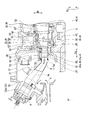
- the gas turbine 1 has a compressor 10 that compresses outside air to generate compressed air A, and a plurality of combustors that mix fuel with the compressed air A and burn it to generate combustion gas G. 20, a turbine 30 driven by the combustion gas G, and a seal member 7 disposed between the combustor 20 and the turbine 30.
- the turbine 30 includes a casing 31 and a turbine rotor 33 that rotates around the rotor axis Ar in the casing 31.
- the turbine rotor 33 is connected to, for example, a generator (not shown) that generates electric power by the rotation of the turbine rotor 33.
- the compressor 10 is disposed on one side of the rotor shaft Ar with respect to the turbine 30.
- the casing 31 of the turbine 30 has a cylindrical shape around the rotor axis Ar.
- a portion of the compressed air A is supplied to the turbine 30 and the combustor 20 as cooling air.
- the compressed air A pressurized by the compressor 10 is temporarily accumulated in the space in the casing 31.
- the plurality of combustors 20 are attached to the casing 31 at intervals in the circumferential direction Dc with respect to the rotor axis Ar.
- the direction in which the rotor axis Ar extends is taken as an axial direction Da.
- the side where the turbine 30 is disposed with respect to the combustor 20 is the downstream side, and the opposite side is the upstream side.
- the circumferential direction Dc based on the rotor axis Ar is simply referred to as the circumferential direction Dc
- the radial direction Dr based on the rotor axis Ar is simply referred to as the radial direction Dr.
- the side away from the axis Ac is taken as the radial direction Dr
- the opposite side is taken as the radial direction Dr.
- the axis Ac of the combustor 20 in the present embodiment is a line passing through the center of gravity position in each cross section intersecting the extending direction of the transition piece 21 of the combustor 20.
- the turbine rotor 33 has a rotor main body 34 and a plurality of moving blade rows 35.
- the rotor main body 34 extends in the axial direction Da around the rotor axis Ar.
- the plurality of moving blade rows 35 are attached to the rotor body 34 side by side in the axial direction Da.
- each moving blade row 35 includes a plurality of moving blades 36 attached to the rotor shaft Ar in the circumferential direction Dc with respect to the rotor shaft Ar.
- the blade 36 has a blade body 37, a platform 38 and a blade root 39.
- the blade body 37 extends in the radial direction Dr.
- the platform 38 is provided inside the radial direction Dr of the moving blade main body 37.
- the wing roots 39 are provided inside the radial direction Dr of the platform 38.
- the moving blade 36 is fixed to the rotor main body 34 by the blade root 39 being embedded in the rotor main body 34.
- a stator blade row 40 is disposed on the upstream side of each of the plurality of moving blade rows 35.
- a plurality of vanes 41 are arranged in the circumferential direction Dc.
- Each of the vanes 41 has a vane body 42, an outer shroud 43, and an inner shroud 45.
- the vane main body 42 extends outward in the radial direction Dr.
- the outer shroud 43 is provided outside the radial direction Dr of the vane main body 42.
- the inner shroud 45 is provided inside the radial direction Dr of the vane main body 42.
- the first stator blades 41a constituting the first stator blade row 40a disposed most upstream in the axial direction Da seal the seal member 7 with respect to the transition piece 21 of the combustor 20 described later. Connected through.
- a cylindrical blade ring 50 is disposed on the outer side of the moving blade row 35 and the stationary blade row 40 in the radial direction Dr and inside the radial direction Dr of the casing 31 about the rotor axis Ar. ing.
- the wing ring 50 is fixed to the casing 31.
- the outer shroud 43 of the stationary blade 41 and the blade ring 50 are connected by a heat shield ring 52.
- a plurality of split rings 60 arranged in the circumferential direction Dc centering around the rotor axis Ar are disposed.
- the plurality of split rings 60 arranged in the circumferential direction Dc form a ring.
- a moving blade row 35 is disposed on the inner side in the radial direction Dr of the plurality of split rings 60.
- the plurality of split rings 60 arranged in the circumferential direction Dc are all connected to the wing ring 50 by the heat shield ring 52.
- combustion gas flow path Pg through which the combustion gas G flows is formed.
- the combustion gas flow path Pg is annularly defined around the rotor body 34.
- the combustion gas flow path Pg includes the inner shroud 45 and the outer shroud 43 of the plurality of stator blades 41 constituting the stator blade row 40, and the platforms 38 of the plurality of moving blades 36 constituting the downstream moving blade row 35 And a split ring 60 facing the
- the combustor 20 includes a transition piece 21 and a fuel supply device 22.
- the transition piece 21 sends the high temperature and high pressure combustion gas G to the turbine 30.
- the fuel supplier 22 supplies fuel and compressed air A into the transition piece 21.
- the fuel supplier 22 forms a flame inside.
- the fuel supply device 22 has a cylindrical inner cylinder 22a centered on the axis Ac.
- the transition piece 21 is connected to the inner cylinder 22a.
- the transition piece 21 supplies the high temperature and high pressure combustion gas G generated by the inner cylinder 22 a to the turbine 30.
- the transition piece 21 has a cylindrical shape.
- the outlet opening on the downstream side in the axial direction Da has a substantially rectangular shape.
- the transition piece 21 has an outlet flange 210 that protrudes from the outer peripheral surface on the downstream side in the axial direction Da.
- a shroud main body 44 and a side wall 46 are formed on the inner shroud 45 and the outer shroud 43 of the first vane 41 a.
- the shroud main body 44 has a gas path surface 441 facing the combustion gas flow path Pg.
- the side wall 46 intersects the gas path surface 441 and extends from the combustion gas flow path Pg in the radial direction Dr or in the radial direction Dr.
- the side wall 46 is formed with a protrusion 424 extending from the side end surface 461 facing the upstream side in the axial direction Da to the upstream side in the axial direction Da.
- the protrusion 424 is formed at a position away from the gas path surface 441 of the side end surface 461 in the radial direction Dr or at the outer side of the radial direction Dr.
- the projecting portion 424 is formed in an arc shape centering on the rotor axis Ar.
- the outlet flange 210 has a substantially square ring shape so as to cover the outlet opening of the transition piece 21.
- the outlet flange 210 protrudes from the outer peripheral surface of the transition piece 21 toward the outside of the combustion gas flow path Pg.
- the outlet flange 210 has a pair of circumferential flanges 210a and a pair of radial flanges (not shown).
- the pair of circumferential flanges 210 a protrudes from the outer circumferential surface of the outer sleeve 21 extending in the circumferential direction Dc among the outer circumferential surfaces of the transition piece 21 in the direction away from the combustion gas flow path Pg.
- the pair of circumferential flanges 210 a oppose each other in the radial direction Dr with the outlet opening interposed therebetween.
- the rear end portion 211 on the downstream side in the axial direction Da extends toward the downstream side in the axial direction Da with respect to the outlet flange 210.
- the rear end portion 211 is formed such that a surface facing the downstream side in the axial direction Da is opposed to the side end surface 461 of the first stationary blade 41 a with a gap in the axial direction Da.
- the seal member 7 is a tail cylinder seal disposed between the combustor 20 and the first stator vane row 40 a disposed on the downstream side of the combustor 20 in the axial direction Da and facing the combustion gas flow path Pg. .
- the seal member 7 seals between the outlet flange 210 of the transition piece 21 of the combustor 20 and the inner shroud 45 and the outer shroud 43 of the first stationary blade 41 a of the first stationary blade row 40 a.
- the seal member 7 is divided into an inner seal member 7a and an outer seal member 7b.
- the inner seal member 7 a and the outer seal member 7 b are respectively disposed along the circumferential flange portion 210 a of the substantially square annular outlet flange 210 in the radial direction Dr inner side or the radial direction Dr outer side.
- the inner seal member 7a engages with the circumferential flange portion 210a on the inner side in the radial direction Dr and engages with the inner shroud 45 of the first stationary blade 41a.
- the outer seal member 7b engages with the circumferential flange portion 210a on the outer side of the radial direction Dr and engages with the outer shroud 43 of the first stationary blade 41a.
- the inner seal member 7a on the inner side of the radial direction Dr and the outer seal member 7b on the outer side of the radial direction Dr have substantially symmetrical shapes with reference to the axis Ac of the transition piece 21. Therefore, hereinafter, the seal member 7 (inner seal member 7a) engaged with the inner shroud 45 on the inner side in the radial direction Dr will be mainly described as a representative example, but the same applies to the outer seal member 7b.
- the name and reference numeral in the description herein will be described as “seal member 7”.
- the seal member 7 in the present embodiment is disposed on the outer side (inner side in the radial direction Dr) of the combustion gas flow path Pg through which the combustion gas G flows.
- the seal member 7 is disposed in a cavity C formed in the gap between the transition piece 21 and the inner shroud 45 of the first stationary blade 41a, as shown in FIG.
- the cavity C in the present embodiment is a space between the tail cylinder 21 facing the combustion gas flow path Pg and the first stationary blade 41 a.
- the cavity C is formed radially inward of the inner circumferential surface of the transition piece 21 and the gas path surface 441 of the first stationary blade 41 a.
- the cavity C is a space which is located radially inward of the rear end portion 211 of the transition piece 21 in the radial direction Dr and is sandwiched by the outlet flange 210 and the side end surface 461 in the axial direction Da.
- the seal member 7 is annularly formed around the rotor axis Ar when viewed from the downstream side in the axial direction Da.
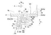
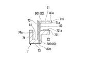
- the seal member 7 according to the present embodiment includes the main body 70, the first convex portion 71, the second convex portion 72, the third convex portion 73, and the third convex portion 73 in the cross section extending in the radial direction Dr including the axis Ac. And four convex portions 74.
- the main body 70 extends in the radial direction Dr.
- the first convex portion 71 protrudes from the end on the outer side in the radial direction Dr of the main body portion 70 to the downstream side in the axial direction Da.
- the second convex portion 72 protrudes from the main body portion 70 downstream in the axial direction Da at a position apart from the first convex portion 71.
- the third convex portion 73 protrudes from the end on the inner side in the radial direction Dr of the main body portion 70 to the upstream side in the axial direction Da.
- the fourth convex portion 74 protrudes outward in the radial direction Dr from the end portion on the upstream side of the third convex portion 73 in the axial direction Da.
- a cooling flow passage 80 and a slit 83 are formed (FIG. 4).
- the cooling channel 80 discharges the cooling air from the opening 80a.
- the slits 83 are recessed in the radial direction Dr from the surface facing the combustion gas flow path Pg side.
- the main body portion 70 of the present embodiment extends in the radial direction Dr including the axis Ac and has a substantially rectangular shape whose cross section is long in the radial direction Dr.
- a cooling flow passage 80 (802) extending in the radial direction is formed in the main body portion 70.
- An inlet port 80 b opening to a space in the casing 31 is formed on the radially inner end surface.
- the first convex portion 71 protrudes from the end portion of the main body portion 70 on the outer side in the radial direction Dr toward the side end surface 461 on the downstream side in the axial direction Da.
- a transverse cross-section extending in the radial direction Dr including the axis Ac is in a substantially rectangular parallelepiped shape long in the axial direction Da.
- the first convex portion 71 is annularly formed around the rotor axis Ar.
- the first convex portion 71 is formed in a space sandwiched in the axial direction Da by the first end surface 101 of the rear end portion 211 of the tail cylinder 21 and the projecting portion 424.
- the first convex portion 71 is formed with an end surface 71 a facing the side end surface 461 and facing the downstream side of the axial direction Da.
- the cooling flow passage 80 (801) is formed along the axial direction Da.
- a plurality of cooling channels 80 (801) are arrayed at predetermined intervals in a constant region in the circumferential direction.
- a plurality of circular openings 80a communicating with the cooling flow passage 80 (axial flow passage 801) are formed in the end surface 71a.
- the cooling flow passage 80 (axial flow passage 801) communicates with the cooling flow passage 80 (radial flow passage 802) formed in the main body 70 on the upstream side in the axial direction Da.
- a gap forming portion 71b is formed which protrudes to the downstream side in the axial direction Da from the end surface 71a.
- the end surface 71 a of the present embodiment is a surface of an end portion on the downstream side of the axial direction Da, which is an end portion of the first convex portion 71 opposite to the main body portion 70.
- the end surface 71 a of the present embodiment is formed to face the side end surface 461 at the upstream side in the axial direction Da with a gap therebetween.
- the second convex portion 72 protrudes from the main body portion 70 toward the downstream side in the axial direction Da at a position away from the first convex portion 71 in the radial direction Dr.
- the second convex portion 72 has a substantially rectangular parallelepiped shape having a transverse cross-section extending in the radial direction Dr including the axis Ac and extending in the axial direction Da.
- the second convex portion 72 is annularly formed around the rotor axis Ar.
- the second convex portion 72 is formed with a concave groove in which the protruding portion 424 is fitted in the axial direction Da between the second convex portion 72 and the first convex portion 71.
- a contact seal member 721 is fixed to the second convex portion 72 in the present embodiment.
- the contact seal member 721 is a metal plate and is fixed to the surface of the second convex portion 72 facing the first convex portion 71 side.
- the contact seal member 721 has a first seal surface 721 a formed annularly with the projection 424.
- the first seal surface 721 a is in contact with the surface of the protrusion 424 facing inward in the radial direction Dr.
- the first seal surface 721a of the present embodiment is a surface facing the first convex portion 71 side which is the outer side in the radial direction Dr of the contact seal member 721.
- the third convex portion 73 protrudes from the end portion inside the radial direction Dr of the main body portion 70 toward the opposite side to the first convex portion 71 on the upstream side of the axial direction Da.
- the third convex portion 73 of the present embodiment has a substantially rectangular parallelepiped shape having a transverse cross-section extending in the radial direction Dr including the axis Ac and extending in the axial direction Da.
- the third convex portion 73 is formed at a position inside the radial direction Dr than the circumferential flange portion 210a.
- the fourth convex portion 74 protrudes from the end portion on the upstream side in the axial direction Da of the third convex portion 73 toward the outer peripheral surface of the tail cylinder 21.
- the fourth convex portion 74 has a substantially rectangular parallelepiped shape in which a transverse cross-section extending in the radial direction Dr including the axis Ac is long in the radial direction Dr.
- the fourth convex portion 74 protrudes from the third convex portion 73 at a position upstream of the circumferential flange portion 210 a in the axial direction Da.
- a second seal surface 70a is formed on the surface of the main body 70 facing the upstream side of the axial direction Da, with which the surface of the circumferential flange portion 210a facing the downstream side of the axial direction Da contacts. That is, the surface of the circumferential flange portion 210a facing the downstream side in the axial direction Da receives a differential pressure between the pressure of the compressed air A in the casing 31 and the pressure on the combustion gas flow path Pg side. It is pressed against the surface of the main body 70 facing the upstream side in the axial direction Da.
- the second seal is sealed in contact with the surface of the circumferential flange portion 210 a facing the downstream side of the axial direction Da on the surface of the main body 70 facing the upstream side of the axial direction Da.
- the surface 70a is always formed.
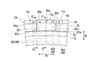
- a plurality of openings 80a in the present embodiment are formed at predetermined intervals in the circumferential direction Dc over a predetermined region of the end face 71a.
- the opening 80 a includes the position on the upstream side in the axial direction Da of the front edge 421 with respect to the front edge 421 which is a region facing the upstream side in the axial direction Da of the vane main body 42, It forms in the fixed area
- the opening 80a of the present embodiment is formed on the upstream side of the axial direction Da of the front edge 421 so that the position in the circumferential direction Dc corresponds to the position where the front edge 421 of the vane main body 42 is formed.
- the cooling flow passage 80 having the opening 80a is circumferentially provided along the axial direction Da centering on the position on the upstream side of the axial direction Da corresponding to the position where the front edge portion 421 of the vane main body 42 is formed. It is arranged in multiples.
- the range in which the cooling channels 80 are arranged is limited to a partial region of a certain range in the circumferential direction, and it is not necessary to be disposed over the entire length in the circumferential direction of the first convex portion 71.
- the gap forming portion 71b is disposed adjacent to the end surface 71a in which the opening 80a is formed in the circumferential direction Dc.
- the gap forming portion 71 b protrudes from the end surface 71 a toward the side end surface 461 on the downstream side in the axial direction Da.
- the gap forming portion 71b of the present embodiment is formed so as to sandwich a predetermined region of the end surface 71a where the opening 80a is formed from the outside in the circumferential direction Dc.
- the cooling flow passage 80 takes in the compressed air A as cooling air from the space in the casing 31 of the turbine 30, circulates the flow in the flow passage, and jets it from the opening 80a toward the side end surface 461.
- the cooling passage 80 of the present embodiment is circular in cross section.
- a plurality of cooling channels 80 are formed through the inside of the main body portion 70 and the first convex portion 71.
- the cooling flow passage 80 of the present embodiment has an axial flow passage 801 and a radial flow passage 802.
- the axial flow passage 801 is formed toward the upstream side in the axial direction Da from the opening 80 a.
- the radial flow passage 802 communicates with the axial direction Da on the upstream side of the axial flow passage 801 and is formed inward in the radial direction Dr.
- the slits 83 are recessed in the radial direction Dr from the surface facing the outer side of the radial direction Dr, which is the surface on the combustion gas flow path Pg side of the main body portion 70 and the first convex portion 71.
- a plurality of slits 83 are formed in the circumferential direction Dc away from the opening 80a in a region adjacent to the axial flow passage 801 connected to the opening 80a.
- the slit 83 in the present embodiment is formed in an elongated groove shape so as to divide the end surface 71a in which the opening 80a is formed in the axial direction Da.
- the position of the slit bottom portion 83a which is the end of the cut formed on the outer side with respect to the combustion gas flow path Pg, is the position where the first seal surface 721a of the second convex portion 72 is formed.
- the second sealing surface 70 a of the main body 70 is disposed at a position closer to the combustion gas flow path Pg than the innermost position in the radial direction Dr.
- the position of the slit bottom 83a faces the radial direction Dr of the first seal surface 721a and the innermost position of the radial direction Dr of the second seal surface 70a. Also, it is recessed in the radial direction Dr from the surface on the combustion gas flow path Pg side of the main body portion 70 and the first convex portion 71 so as to be formed at the position outside the radial direction Dr.
- the seal member 7 of the present embodiment is connected to the first engagement portion 81 connected to the transition piece 21 of the combustor 20 on the upstream side in the axial direction Da and to the inner shroud 45 of the first stationary blade 41 a on the downstream side in the axial direction Da. And a second engaging portion 82.
- the first engagement portion 81 seals the compressed air A in the casing 31 from between the outlet flange 210 and the seal member 7 so as not to leak toward the combustion gas flow path Pg.
- the first engaging portion 81 of the present embodiment is constituted by the main body portion 70, the third convex portion 73, and the fourth convex portion 74.
- the first engaging portion 81 of the present embodiment includes a surface facing the upstream side of the main body 70 in the axial direction Da, a surface facing the outer side of the third convex portion 73 in the radial direction Dr, and a second seal of the fourth convex portion 74.
- the circumferential flange portion 210a is fitted in the radial direction Dr into a groove formed by the surface 70a.
- the second seal surface 70a is formed on the surface where the surface of the circumferential flange portion 210a facing the downstream side of the axial direction Da contacts the surface of the main body 70 facing the upstream side of the axial direction Da.
- the second engagement portion 82 engages the projection 424 and the seal member 7, and the compressed air A in the casing 31 leaks to the combustion gas flow path Pg side from between the projection 424 and the seal member 7. There is no seal.
- the second engagement portion 82 of the present embodiment is configured by the main body portion 70, the first convex portion 71, and the second convex portion 72.
- the second engagement portion 82 of the present embodiment includes a surface facing the downstream side of the main body 70 in the axial direction Da, a surface facing the inner side of the first convex portion 71 in the radial direction Dr, and a second convex portion.
- This is a groove formed by the first seal surface 721a of 72.
- the protrusion 424 is fitted into the groove which is the second engagement portion 82 from the downstream side of the axial direction Da toward the upstream side.
- the first seal surface 721a is in contact with the surface of the protrusion 424 facing inward in the radial direction Dr.
- the seal member 7 is engaged with the outlet flange 210 of the transition piece 21 and the projection 424 of the inner shroud 45 by the first engagement portion 81 and the second engagement portion 82. Thereby, the sealability between the seal member 7 and the outlet flange 210 is maintained.
- the compressed air A from the compressor 10 enters the space in the casing 31 of the turbine 30 and is supplied into the combustor 20.
- the combustor 20 fuel supplied from the outside along with the compressed air A is burned in the inner cylinder 22a to generate combustion gas G.
- the combustion gas G flows into the combustion gas flow path Pg of the turbine 30 via the transition piece 21.
- the combustion gas G contacts the moving blade main body 37 in the process of passing through the combustion gas flow path Pg, and rotates the turbine rotor 33 around the rotor axis Ar.
- the pressure in the casing 31 is higher than the pressure in the cavity C in communication with the combustion gas flow path Pg. Therefore, the differential pressure between the compressed air A and the combustion gas G causes the outlet flange 210 to be pressed against the seal member 7 on the downstream side in the axial direction Da, and the seal member 7 enters the outlet flange 210 via the first engagement portion 81. It is engaged.
- the seal member 7 is engaged with the protrusion 424 via the second engagement portion 82.
- the first seal surface 721 a of the contact seal member 721 provided on the second protrusion 72 is pressed against the surface of the protrusion 424 facing inward in the radial direction Dr. Thereby, the space between the first seal surface 721 a and the surface of the protrusion 424 facing inward in the radial direction Dr is sealed.
- part of the compressed air A that has entered the casing 31 from the compressor 10 flows into the cooling flow passage 80 of the seal member 7 to cool the seal member 7 itself.
- the compressed air A in the casing 31 flows into the axial flow path 801 from the inflow port 80 b, flows through the radial flow path 802, and is jetted out of the opening 80 a into the cavity C. Thereby, the main body 70 and the first convex portion 71 exposed to the combustion gas G are cooled.
- the opening 80a is closed even if the end face 71a and the side end face 461 of the inner shroud 45 approach due to the gap forming portion 71b protruding from the end face 71a. Can be prevented.
- the inner shroud 45 and the seal member 7 approach the axial direction Da due to the difference in thermal elongation of the transition piece 21, the inner shroud 45, and the seal member 7, and the end surface 71a of the seal member 7
- the distance between the shroud 45 and the side end surface 461 is narrowed. As a result, when the end surface 71a and the side end surface 461 contact, there is a possibility that the opening 80a provided in the end surface 71a may be closed.
- the gap forming portion 71 b protrudes on the downstream side in the axial direction Da from the end surface 71 a in which the opening 80 a is formed. Therefore, even if the distance between the end surface 71 a of the first convex portion 71 and the side end surface 461 of the inner shroud 45 becomes narrow, the gap forming portion 71 b contacts the side end surface 461 before the opening 80 a is closed. Thus, the space in front of the opening 80a (the downstream side in the axial direction Da) can be stably secured, and the necessary cooling air can be stably discharged from the opening 80a even when the distance between the end face 71a and the side end face 461 is narrowed. You can continue.
- the gap forming portion 71b serves as a stopper in the axial direction Da of the opening 80a. Therefore, a fixed gap is reliably formed between the end face 71a where the opening 80a is disposed and the side end face 461. Therefore, the opening 80 a is prevented from being closed by providing the gap forming portion 71 b. Therefore, the compressed air A can be stably circulated as cooling air with respect to the axial flow passage 801 and the radial flow passage 802. Thereby, the seal member 7 can be cooled stably and continuously.
- the seal member 7 By arranging the seal member 7 on the outer side in the radial direction Dr with respect to the combustion gas flow path Pg, it is possible to prevent the seal member 7 itself from being in direct contact with the high temperature combustion gas G flowing through the combustion gas flow path Pg. . Therefore, the seal member 7 is only exposed to a part of the combustion gas G flowing from the gap between the rear end portion 211 of the transition piece 21 and the end surface 71a of the inner shroud 45. As a result, the seal member 7 itself becomes hot. Can be suppressed.
- the position in the circumferential direction Dc of the opening 80a provided on the end face 71a is formed on the upstream side in the axial direction Da of the front edge 421 so as to correspond to the position where the front edge 421 of the vane main body 42 is formed There is. Therefore, the sealing member 7 that is heated to a high temperature can be effectively cooled by the inclusion of the combustion gas G that has collided with the front edge portion 421 of the vane main body 42.
- the combustion gas G collides with the front edge portion 421, and the combustion gas G is wound in the vicinity of the upstream side of the front edge portion 421 in the axial direction Da.
- the combustion gas G can be easily introduced into the cavity C from the gap between the surface 211 and the end surface 71 a of the inner shroud 45. Therefore, in the vicinity of the upstream side in the axial direction Da of the front edge portion 421, the main body portion 70 and the first convex portion 71 become partially high in temperature due to the combustion of the combustion gas G.
- the cooling flow passage 80 it is not necessary to arrange the cooling flow passage 80 over the entire length of the first convex portion 71 in the circumferential direction Dc, and the cooling flow passage 80 is partially located in the vicinity of the upstream position of the axial direction Da corresponding to the front edge 421 An opening 80 a is provided at the end of the cooling flow passage 80 on the downstream side in the axial direction Da. Therefore, the cooling air can be efficiently supplied to the portion which becomes high temperature in the main body portion 70 and the first convex portion 71 to cool the seal member 7. That is, the seal member 7 may be disposed outside the combustion gas channel Pg, and the cooling channel 80 may be partially disposed in the circumferential direction Dc. Therefore, the flow rate of the cooling air can be further suppressed as a whole of the seal member 7. As a result, the flow rate of the compressed air A used as the cooling air can be reduced, and the performance deterioration of the gas turbine 1 can be further suppressed.
- the opening 80a By forming the gap forming portion 71b so as to sandwich a predetermined region of the end face 71a in which the opening 80a is formed from the outside in the circumferential direction Dc, the opening 80a can be disposed close to the gap forming portion 71b. Therefore, the space in front of the opening 80a can be secured with high accuracy by the gap forming portion 71b. Therefore, the opening 80a is prevented from being blocked, and the compressed air A can be more stably circulated as cooling air with respect to the axial flow passage 801 and the radial flow passage 802. Thereby, the seal member 7 can be cooled more stably and continuously.
- the compressed air A flows through the axial flow passage 801 and the radial flow passage 802 to partially cool the main body 70 and the first convex portion 71 in the circumferential direction Dc.
- a temperature distribution is generated in the circumferential direction Dc in the portion where the cooling flow passage 80 is formed in the main body portion 70 and the first convex portion 71 and the periphery thereof. Therefore, a distribution of thermal stress is generated in the circumferential direction Dc inside the seal member 7, and distortion occurs due to the thermal elongation difference.
- the rigidity of the main body portion 70 and the first convex portion 71 can be lowered.
- the seal member 7 itself is easily bent, and distortion generated in the main body portion 70 and the first convex portion 71 can be absorbed by the distribution of the thermal stress in the circumferential direction Dc.
- the slit bottom portion 83a is disposed closer to the combustion gas flow path Pg side than the radial direction Dr inner end (the radial direction Dr inner end of the outlet flange 210) of the second seal surface 70a formed in the main body portion 70, and It is disposed on the side closer to the combustion gas flow path Pg side than the first seal surface 721 a of the contact seal member 721 disposed on the first convex portion 71. Therefore, the slit 83 can be formed while maintaining the sealed state by the first seal surface 721a and the second seal surface 70a.
- FIG. 8 is a cross-sectional view of the seal member 7 as viewed in the circumferential direction from the plane including the slits 83, and shows the IX-IX cross section in FIG.
- FIG. 9 shows a VIII-VIII cross section in FIG.
- the seal member 7 described below is an explanation for the inner seal member 7a, the same concept can be applied to the outer seal member 7b.
- the seal member 7 shown in the present modification is disposed outside the combustion gas flow path Pg, as in the first embodiment.
- the seal member 7 is disposed in a cavity C formed in the gap between the transition piece 21 and the inner shroud 45 of the first stationary blade 41 a.
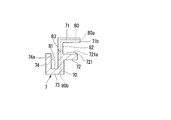
- the gap forming portion 71 c of the sealing member 7 in the present modification is formed at an end surface 71 a facing the downstream side of the axial direction Da at the downstream end of the first convex portion 71 in the axial direction Da.
- the gap forming portion 71c is formed on the end surface 71a inward of the opening 80a in the radial direction Dr.
- the gap forming portion 71c protrudes from the end surface 71a to the downstream side in the axial direction Da.
- the gap forming portion 71c is integrally formed with the end surface 71a.
- the gap forming portion 71c extends in the circumferential direction Dc.
- the gap forming portion 71 c is formed on the inner side in the radial direction Dr with respect to the opening 80 a of the cooling flow passage 80 formed on the end surface 71 a.
- the cooling flow passage 80 does not have to be disposed over the entire region in the circumferential direction Dc, and may be partially disposed in the circumferential direction Dc.
- the cooling channel 80 is disposed in a fixed region in the circumferential direction Dc including the opposing position on the upstream side of the axial direction Da with respect to the front edge portion 421 of the vane main body 42 in the same manner as in the first embodiment. is there.
- the gap forming portion 71c may be provided over the entire area of the circumferential direction Dc at the end surface 71a on the downstream side of the first convex portion 71 in the axial direction Da as in this modification, and a partial area in the circumferential direction Dc It may be provided.
- slits 83 are formed in the main body 70 and the first convex portion 71 at regular intervals in the circumferential direction Dc, as in the first embodiment.
- the end face 71a is Before contacting the side end surface 461 of the inner shroud 45, the end surface on the downstream side in the axial direction Da of the gap forming portion 71 c contacts the side end surface 461. Therefore, a gap is reliably formed in front of the opening 80a (the downstream side in the axial direction), and the opening 80a is not blocked. That is, the gap forming portion 71c plays a role of a stopper for preventing blocking in the axial direction Da of the opening 80a.
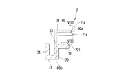
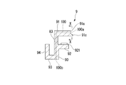
- FIG. 10 is an enlarged view of a main part around the seal member in the present embodiment.
- the structure in which the seal member 9 is formed of the main body portion 90, the first convex portion 91, the second convex portion 92, the third convex portion 93, and the fourth convex portion 94 is the seal in the first embodiment.
- the seal member 9 is disposed between the transition piece 21 and the inner shroud 45.
- the first convex portion 91 faces the combustion gas flow path Pg to form a part of the combustion gas flow path Pg. Therefore, the outer surface (gas path surface 911) of the first convex portion 91 facing the combustion gas flow path Pg is exposed to the high temperature combustion gas G.
- the cooling flow passage 100 extending in the axial direction Da is arranged.
- the cooling flow passage 100 of the second embodiment is disposed over the entire surface in the circumferential direction Dc of the first convex portion 91 at a predetermined interval in the circumferential direction Dc.
- An opening 100 a connected to the cooling flow passage 100 is formed on the end surface 91 a of the first convex portion 91 on the downstream side in the axial direction Da.
- the compressed air A used for the cooling air is supplied from the space in the casing 31 to the inflow port 100 b formed at the radial direction Dr inner end of the main body 90 of the sealing member 9, and the inflow port 100 b to the cooling flow path 100. Communication is the same as in the first embodiment.
- a clearance forming portion 91 b is formed on the end surface 91 a on the downstream side in the axial direction Da of the first convex portion 91 so as to protrude from the end surface 91 a on the downstream side in the axial direction Da.
- the gap forming portion 91b is integrally formed with the end surface 91a at a gap in the circumferential direction Dc.
- the end surface of the gap forming portion 91b facing the downstream side in the axial direction Da faces the side end surface 461 formed on the side wall 46 of the first stationary blade 41a adjacent to the downstream side of the axial direction Da with a gap.
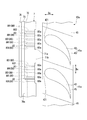
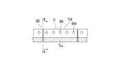
- FIG. 11 is a plan view of the seal member 9 in FIG. 10 as viewed in the radial direction Dr from the combustion gas flow path Pg side.
- the cooling flow passage 100 is extended in the axial direction Da of the first convex portion 91 of the sealing member 9.
- the cooling channels 100 are arranged at predetermined intervals in the circumferential direction Dc.
- An opening 100 a is formed on the end surface 91 a of the cooling flow passage 100 on the downstream side in the axial direction Da.
- a gap forming portion 91b is formed adjacent to the circumferential direction Dc with respect to the end face 91a in which the openings 100a are arranged.
- the gap forming portion 91b protrudes downstream in the axial direction Da with respect to the end surface 91a.
- FIG. 11 is a plan view of the seal member 9 in FIG. 10 as viewed in the radial direction Dr from the combustion gas flow path Pg side.
- the cooling flow passage 100 is extended in the axial direction Da of the first convex
- a gap forming portion 91b is provided between the cooling channels 100 adjacent in the circumferential direction Dc.
- a gap forming portion 91b is provided adjacent to one cooling channel 100 so as to be sandwiched in the circumferential direction Dc.
- one gap forming portion 91c may be provided in the circumferential direction Dc with respect to the plurality of cooling flow paths 100 and the openings 100a.
- the cooling flow passage 100 is disposed over the entire circumferential direction Dc of the first convex portion 91, so the temperature distribution width in the circumferential direction Dc is not as large as in the first embodiment. Therefore, in the case of the seal member 9 of the second embodiment, the main body 90 and the first convex portion 91 may not be provided with the slits 83 for absorbing the thermal stress in the circumferential direction Dc.
- the difference between the thermal expansions of the transition piece 21, the inner shroud 45, and the seal member 9 makes the inner shroud 45 and the seal member 9 in the axial direction Da.
- the end surface on the downstream side of the axial direction Da of the gap forming portion 91b contacts the side end surface 461 before the end surface 91a contacts the side end surface 461 of the inner shroud 45. Therefore, a gap is formed in front of the opening 100a (the downstream side in the axial direction Da), and the opening 100a is not closed. That is, since the gap forming portion 91b serves as a stopper in the axial direction Da of the opening 100a, a constant gap is surely formed between the end surface 91a where the opening 100a is disposed and the side end surface 461.
- the present modification shows a modification of the seal member applied to the second embodiment.
- the structure around the gap forming portion of the seal member of the modification of the second embodiment is basically the same as that of the modification of the first embodiment.
- the sealing member 9 of the modification of 2nd embodiment is demonstrated using FIG.12 and FIG.13, also in this modification, the inner side sealing member 9a is demonstrated below.
- the same concept can be applied to the outer seal member 9b.
- 12 shows a cross section of the seal member 9 as viewed from the circumferential direction Dc
- FIG. 13 shows a cross section (X-X cross section of FIG. 12) of the end face 91a as viewed from the downstream side of the axial direction Da.
- the seal member 9 in the present modification is disposed between the transition piece 21 and the inner shroud 45 as in the second embodiment.
- the first convex portion 91 faces the combustion gas flow path Pg to form a part of the combustion gas flow path Pg. Therefore, the outer surface (gas path surface 911) of the first convex portion 91 facing the combustion gas flow path Pg is exposed to the high temperature combustion gas G.
- the gap forming portion 91c of the seal member 9 shown in the present modification is an end surface 91a on the downstream side of the first convex portion 91 in the axial direction Da and is formed inside the radial direction Dr than the opening 100a. There is.
- the gap forming portion 91c protrudes from the end surface 91a downstream in the axial direction Da, is integrally formed with the end surface 91a in the circumferential direction Dc, and extends in the circumferential direction Dc.
- the sealing member 9 shown in the modification of the second embodiment is different from the sealing member 7 shown in the modification of the first embodiment in that the arrangement of the cooling flow path is different and the slit is not provided.
- the cooling flow passage 100 of the present modification is formed in a plurality over the entire region in the circumferential direction Dc of the first convex portion 91.
- the cooling flow passage 100 is partially disposed in a partial region of the circumferential direction Dc. As shown in FIG.
- the slits 83 are provided to absorb the thermal stress in the circumferential direction Dc of the seal member 7, but in the case of this modification, the circumferential direction Since the temperature distribution of Dc is small, the slit 83 need not be provided.
- the end face on the downstream side of the axial direction Da of the gap forming portion 91c first contacts the opposing side end face 461. Therefore, a gap is formed in front of the opening 100 a (the downstream side in the axial direction Da), and the opening 100 a is not blocked. That is, since the gap forming portion 91c serves as a stopper in the axial direction Da of the opening 100a, a constant gap is surely formed between the end surface 91a where the opening 100a is disposed and the side end surface 461.
- the gap forming portions 71b, 71c, 91b, and 91c are not limited to the shapes disposed adjacent to the openings 80a and 100a in the circumferential direction Dc as in the present embodiment.
- the gap forming portions 71b, 71c, 91b, 91c only need to form a space between the end surfaces 71a, 91a provided with the openings 80a, 100a so as not to close the openings 80a, 100a and the side end surfaces 461 of the inner shroud 45. .
- the openings 80a and 100a formed in line in the circumferential direction Dc are formed in the same shape, but the present invention is not limited to this.
- the openings 80a and 100a may have any shape in the circumferential direction Dc.
- the openings 80a and 100a formed on the upstream side of the front edge 421 in the axial direction Da are formed large, and the openings 80a and 100a formed on a position other than the upstream side of the front edge 421 in the axial direction Da are formed small. May be
- the cooling air can be circulated without closing the opening, and the seal member can be stably and continuously cooled.
Landscapes
- Engineering & Computer Science (AREA)
- General Engineering & Computer Science (AREA)
- Mechanical Engineering (AREA)
- Chemical & Material Sciences (AREA)
- Combustion & Propulsion (AREA)
- Turbine Rotor Nozzle Sealing (AREA)
- Sealing Using Fluids, Sealing Without Contact, And Removal Of Oil (AREA)
Priority Applications (4)
| Application Number | Priority Date | Filing Date | Title |
|---|---|---|---|
| KR1020177007680A KR101939508B1 (ko) | 2014-09-26 | 2015-09-08 | 시일 부재 |
| US15/512,760 US10724392B2 (en) | 2014-09-26 | 2015-09-08 | Seal member |
| CN201580050889.7A CN107076028B (zh) | 2014-09-26 | 2015-09-08 | 密封构件 |
| DE112015004378.0T DE112015004378B4 (de) | 2014-09-26 | 2015-09-08 | Dichtungselement |
Applications Claiming Priority (2)
| Application Number | Priority Date | Filing Date | Title |
|---|---|---|---|
| JP2014-196772 | 2014-09-26 | ||
| JP2014196772A JP6512573B2 (ja) | 2014-09-26 | 2014-09-26 | シール部材 |
Publications (1)
| Publication Number | Publication Date |
|---|---|
| WO2016047432A1 true WO2016047432A1 (ja) | 2016-03-31 |
Family
ID=55580960
Family Applications (1)
| Application Number | Title | Priority Date | Filing Date |
|---|---|---|---|
| PCT/JP2015/075439 WO2016047432A1 (ja) | 2014-09-26 | 2015-09-08 | シール部材 |
Country Status (6)
Cited By (1)
| Publication number | Priority date | Publication date | Assignee | Title |
|---|---|---|---|---|
| US20180266263A1 (en) * | 2017-03-15 | 2018-09-20 | Safran Aircraft Engines | Air-fire seal and assembly comprising such a seal |
Families Citing this family (5)
| Publication number | Priority date | Publication date | Assignee | Title |
|---|---|---|---|---|
| JP7214332B2 (ja) * | 2017-01-18 | 2023-01-30 | ゼネラル・エレクトリック・カンパニイ | ガスタービンの燃焼システムにおける段階的な燃料および空気噴射 |
| FR3081511B1 (fr) * | 2018-05-28 | 2020-06-05 | Safran Aircraft Engines | Dispositif d'etancheite entre deux parois annulaires d'un moteur d'aeronef |
| JP7451108B2 (ja) * | 2019-08-16 | 2024-03-18 | 三菱重工業株式会社 | 静翼、及びこれを備えているガスタービン |
| US11619174B2 (en) * | 2020-02-14 | 2023-04-04 | Raytheon Technologies Corporation | Combustor to vane sealing assembly and method of forming same |
| US12025058B2 (en) * | 2021-03-09 | 2024-07-02 | Mitsubishi Heavy Industries, Ltd. | Sealing member and gas turbine |
Citations (5)
| Publication number | Priority date | Publication date | Assignee | Title |
|---|---|---|---|---|
| JP2000257862A (ja) * | 1999-03-08 | 2000-09-22 | Mitsubishi Heavy Ind Ltd | 燃焼器の尾筒シール構造及びその構造を用いたガスタービン |
| JP2001289003A (ja) * | 2000-04-04 | 2001-10-19 | Mitsubishi Heavy Ind Ltd | ガスタービンの冷却構造 |
| JP2004225688A (ja) * | 2003-01-22 | 2004-08-12 | Mitsubishi Heavy Ind Ltd | ガスタービン尾筒シール及びこれを用いたガスタービン |
| JP2006105076A (ja) * | 2004-10-08 | 2006-04-20 | Mitsubishi Heavy Ind Ltd | ガスタービン |
| JP2013221455A (ja) * | 2012-04-17 | 2013-10-28 | Mitsubishi Heavy Ind Ltd | ガスタービン、及びその高温部品 |
Family Cites Families (7)
| Publication number | Priority date | Publication date | Assignee | Title |
|---|---|---|---|---|
| US4502809A (en) * | 1981-08-31 | 1985-03-05 | Carrier Corporation | Method and apparatus for controlling thermal growth |
| US6675584B1 (en) | 2002-08-15 | 2004-01-13 | Power Systems Mfg, Llc | Coated seal article used in turbine engines |
| GB0515868D0 (en) | 2005-08-02 | 2005-09-07 | Rolls Royce Plc | Cooling arrangement |
| US7797948B2 (en) * | 2007-03-27 | 2010-09-21 | Siemens Energy, Inc. | Transition-to-turbine seal apparatus and transition-to-turbine seal junction of a gas turbine engine |
| JP2009167905A (ja) | 2008-01-16 | 2009-07-30 | Mitsubishi Heavy Ind Ltd | ガスタービン燃焼器出口シール構造 |
| FR2937098B1 (fr) | 2008-10-15 | 2015-11-20 | Snecma | Etancheite entre une chambre de combustion et un distributeur de turbine dans une turbomachine |
| JP6016655B2 (ja) | 2013-02-04 | 2016-10-26 | 三菱日立パワーシステムズ株式会社 | ガスタービン尾筒シール及びガスタービン |
-
2014
- 2014-09-26 JP JP2014196772A patent/JP6512573B2/ja active Active
-
2015
- 2015-09-08 WO PCT/JP2015/075439 patent/WO2016047432A1/ja active Application Filing
- 2015-09-08 DE DE112015004378.0T patent/DE112015004378B4/de active Active
- 2015-09-08 CN CN201580050889.7A patent/CN107076028B/zh active Active
- 2015-09-08 KR KR1020177007680A patent/KR101939508B1/ko active Active
- 2015-09-08 US US15/512,760 patent/US10724392B2/en active Active
Patent Citations (5)
| Publication number | Priority date | Publication date | Assignee | Title |
|---|---|---|---|---|
| JP2000257862A (ja) * | 1999-03-08 | 2000-09-22 | Mitsubishi Heavy Ind Ltd | 燃焼器の尾筒シール構造及びその構造を用いたガスタービン |
| JP2001289003A (ja) * | 2000-04-04 | 2001-10-19 | Mitsubishi Heavy Ind Ltd | ガスタービンの冷却構造 |
| JP2004225688A (ja) * | 2003-01-22 | 2004-08-12 | Mitsubishi Heavy Ind Ltd | ガスタービン尾筒シール及びこれを用いたガスタービン |
| JP2006105076A (ja) * | 2004-10-08 | 2006-04-20 | Mitsubishi Heavy Ind Ltd | ガスタービン |
| JP2013221455A (ja) * | 2012-04-17 | 2013-10-28 | Mitsubishi Heavy Ind Ltd | ガスタービン、及びその高温部品 |
Cited By (5)
| Publication number | Priority date | Publication date | Assignee | Title |
|---|---|---|---|---|
| US20180266263A1 (en) * | 2017-03-15 | 2018-09-20 | Safran Aircraft Engines | Air-fire seal and assembly comprising such a seal |
| FR3064029A1 (fr) * | 2017-03-15 | 2018-09-21 | Safran Aircraft Engines | Joint d’etancheite air-feu et assemblage comprenant un tel joint |
| US10598037B2 (en) | 2017-03-15 | 2020-03-24 | Safran Aircraft Engines | Air-fire seal and assembly comprising such a seal |
| US11098607B2 (en) | 2017-03-15 | 2021-08-24 | Safran Aircraft Engines | Air-fire seal and assembly comprising such a seal |
| GB2562582B (en) * | 2017-03-15 | 2022-01-05 | Safran Aircraft Engines | Air-fire seal and assembly comprising such a seal |
Also Published As
| Publication number | Publication date |
|---|---|
| JP2016070082A (ja) | 2016-05-09 |
| US20170292397A1 (en) | 2017-10-12 |
| DE112015004378B4 (de) | 2023-03-02 |
| DE112015004378T5 (de) | 2017-06-14 |
| JP6512573B2 (ja) | 2019-05-15 |
| CN107076028A (zh) | 2017-08-18 |
| KR101939508B1 (ko) | 2019-01-16 |
| US10724392B2 (en) | 2020-07-28 |
| KR20170043641A (ko) | 2017-04-21 |
| CN107076028B (zh) | 2019-06-04 |
Similar Documents
| Publication | Publication Date | Title |
|---|---|---|
| WO2016047432A1 (ja) | シール部材 | |
| KR101852290B1 (ko) | 터빈 정익, 터빈, 및 터빈 정익의 개조 방법 | |
| US8277177B2 (en) | Fluidic rim seal system for turbine engines | |
| JP6366180B2 (ja) | シール構造 | |
| CN107435561B (zh) | 用于冷却涡轮叶片的尖端叶冠的密封导轨的系统 | |
| US9518478B2 (en) | Microchannel exhaust for cooling and/or purging gas turbine segment gaps | |
| US8348608B2 (en) | Turbomachine rotor cooling | |
| JP5848439B2 (ja) | シール部材、タービン、及びガスタービン | |
| JP2012112379A (ja) | 一体形ダイアフラムを有するターボ機械ノズルセグメント | |
| KR102272728B1 (ko) | 증기 터빈 및 증기 터빈 조립 방법 | |
| KR101660679B1 (ko) | 가스터빈의 고온부품, 이를 구비하는 가스터빈, 및 가스터빈의 고온부품 제조방법 | |
| KR101833660B1 (ko) | 날개열, 가스터빈 | |
| JP6016655B2 (ja) | ガスタービン尾筒シール及びガスタービン | |
| CN107438701A (zh) | 涡轮机翼型件的在两个压力下的冷却 | |
| JP5852191B2 (ja) | 端壁部材及びガスタービン | |
| US10738638B2 (en) | Rotor blade with wheel space swirlers and method for forming a rotor blade with wheel space swirlers | |
| US20240368995A1 (en) | Rotor and turbomachine comprising the rotor | |
| JP5852190B2 (ja) | 端壁部材及びガスタービン | |
| EP3816402B1 (en) | Stator assembly for a gas turbine and gas turbine comprising said stator assembly | |
| JP2013234672A (ja) | 端壁部材及びガスタービン |
Legal Events
| Date | Code | Title | Description |
|---|---|---|---|
| 121 | Ep: the epo has been informed by wipo that ep was designated in this application |
Ref document number: 15843347 Country of ref document: EP Kind code of ref document: A1 |
|
| WWE | Wipo information: entry into national phase |
Ref document number: 15512760 Country of ref document: US |
|
| ENP | Entry into the national phase |
Ref document number: 20177007680 Country of ref document: KR Kind code of ref document: A |
|
| WWE | Wipo information: entry into national phase |
Ref document number: 112015004378 Country of ref document: DE |
|
| 122 | Ep: pct application non-entry in european phase |
Ref document number: 15843347 Country of ref document: EP Kind code of ref document: A1 |