WO2016047239A1 - 緩衝部材 - Google Patents
緩衝部材 Download PDFInfo
- Publication number
- WO2016047239A1 WO2016047239A1 PCT/JP2015/069663 JP2015069663W WO2016047239A1 WO 2016047239 A1 WO2016047239 A1 WO 2016047239A1 JP 2015069663 W JP2015069663 W JP 2015069663W WO 2016047239 A1 WO2016047239 A1 WO 2016047239A1
- Authority
- WO
- WIPO (PCT)
- Prior art keywords
- pair
- leg pieces
- bottom plate
- member according
- packaging box
- Prior art date
- Legal status (The legal status is an assumption and is not a legal conclusion. Google has not performed a legal analysis and makes no representation as to the accuracy of the status listed.)
- Ceased
Links
Images




Classifications
-
- B—PERFORMING OPERATIONS; TRANSPORTING
- B65—CONVEYING; PACKING; STORING; HANDLING THIN OR FILAMENTARY MATERIAL
- B65D—CONTAINERS FOR STORAGE OR TRANSPORT OF ARTICLES OR MATERIALS, e.g. BAGS, BARRELS, BOTTLES, BOXES, CANS, CARTONS, CRATES, DRUMS, JARS, TANKS, HOPPERS, FORWARDING CONTAINERS; ACCESSORIES, CLOSURES, OR FITTINGS THEREFOR; PACKAGING ELEMENTS; PACKAGES
- B65D81/00—Containers, packaging elements, or packages, for contents presenting particular transport or storage problems, or adapted to be used for non-packaging purposes after removal of contents
- B65D81/02—Containers, packaging elements, or packages, for contents presenting particular transport or storage problems, or adapted to be used for non-packaging purposes after removal of contents specially adapted to protect contents from mechanical damage
-
- B—PERFORMING OPERATIONS; TRANSPORTING
- B65—CONVEYING; PACKING; STORING; HANDLING THIN OR FILAMENTARY MATERIAL
- B65D—CONTAINERS FOR STORAGE OR TRANSPORT OF ARTICLES OR MATERIALS, e.g. BAGS, BARRELS, BOTTLES, BOXES, CANS, CARTONS, CRATES, DRUMS, JARS, TANKS, HOPPERS, FORWARDING CONTAINERS; ACCESSORIES, CLOSURES, OR FITTINGS THEREFOR; PACKAGING ELEMENTS; PACKAGES
- B65D5/00—Rigid or semi-rigid containers of polygonal cross-section, e.g. boxes, cartons or trays, formed by folding or erecting one or more blanks made of paper
- B65D5/42—Details of containers or of foldable or erectable container blanks
- B65D5/44—Integral, inserted or attached portions forming internal or external fittings
- B65D5/50—Internal supporting or protecting elements for contents
-
- B—PERFORMING OPERATIONS; TRANSPORTING
- B65—CONVEYING; PACKING; STORING; HANDLING THIN OR FILAMENTARY MATERIAL
- B65D—CONTAINERS FOR STORAGE OR TRANSPORT OF ARTICLES OR MATERIALS, e.g. BAGS, BARRELS, BOTTLES, BOXES, CANS, CARTONS, CRATES, DRUMS, JARS, TANKS, HOPPERS, FORWARDING CONTAINERS; ACCESSORIES, CLOSURES, OR FITTINGS THEREFOR; PACKAGING ELEMENTS; PACKAGES
- B65D5/00—Rigid or semi-rigid containers of polygonal cross-section, e.g. boxes, cartons or trays, formed by folding or erecting one or more blanks made of paper
- B65D5/42—Details of containers or of foldable or erectable container blanks
- B65D5/44—Integral, inserted or attached portions forming internal or external fittings
- B65D5/50—Internal supporting or protecting elements for contents
- B65D5/5028—Elements formed separately from the container body
- B65D5/5035—Paper elements
-
- B—PERFORMING OPERATIONS; TRANSPORTING
- B65—CONVEYING; PACKING; STORING; HANDLING THIN OR FILAMENTARY MATERIAL
- B65D—CONTAINERS FOR STORAGE OR TRANSPORT OF ARTICLES OR MATERIALS, e.g. BAGS, BARRELS, BOTTLES, BOXES, CANS, CARTONS, CRATES, DRUMS, JARS, TANKS, HOPPERS, FORWARDING CONTAINERS; ACCESSORIES, CLOSURES, OR FITTINGS THEREFOR; PACKAGING ELEMENTS; PACKAGES
- B65D5/00—Rigid or semi-rigid containers of polygonal cross-section, e.g. boxes, cartons or trays, formed by folding or erecting one or more blanks made of paper
- B65D5/42—Details of containers or of foldable or erectable container blanks
- B65D5/44—Integral, inserted or attached portions forming internal or external fittings
- B65D5/50—Internal supporting or protecting elements for contents
- B65D5/5028—Elements formed separately from the container body
- B65D5/5035—Paper elements
- B65D5/5038—Tray-like elements formed by folding a blank and presenting openings or recesses
-
- B—PERFORMING OPERATIONS; TRANSPORTING
- B65—CONVEYING; PACKING; STORING; HANDLING THIN OR FILAMENTARY MATERIAL
- B65D—CONTAINERS FOR STORAGE OR TRANSPORT OF ARTICLES OR MATERIALS, e.g. BAGS, BARRELS, BOTTLES, BOXES, CANS, CARTONS, CRATES, DRUMS, JARS, TANKS, HOPPERS, FORWARDING CONTAINERS; ACCESSORIES, CLOSURES, OR FITTINGS THEREFOR; PACKAGING ELEMENTS; PACKAGES
- B65D5/00—Rigid or semi-rigid containers of polygonal cross-section, e.g. boxes, cartons or trays, formed by folding or erecting one or more blanks made of paper
- B65D5/42—Details of containers or of foldable or erectable container blanks
- B65D5/44—Integral, inserted or attached portions forming internal or external fittings
- B65D5/50—Internal supporting or protecting elements for contents
- B65D5/5028—Elements formed separately from the container body
- B65D5/5035—Paper elements
- B65D5/5047—Blocks
- B65D5/505—Blocks formed by folding up one or more blanks to form a hollow block
- B65D5/5052—Blocks formed by folding up one or more blanks to form a hollow block and provided with slits or recesses in which at least a part of the contents are located
-
- B—PERFORMING OPERATIONS; TRANSPORTING
- B65—CONVEYING; PACKING; STORING; HANDLING THIN OR FILAMENTARY MATERIAL
- B65D—CONTAINERS FOR STORAGE OR TRANSPORT OF ARTICLES OR MATERIALS, e.g. BAGS, BARRELS, BOTTLES, BOXES, CANS, CARTONS, CRATES, DRUMS, JARS, TANKS, HOPPERS, FORWARDING CONTAINERS; ACCESSORIES, CLOSURES, OR FITTINGS THEREFOR; PACKAGING ELEMENTS; PACKAGES
- B65D5/00—Rigid or semi-rigid containers of polygonal cross-section, e.g. boxes, cartons or trays, formed by folding or erecting one or more blanks made of paper
- B65D5/42—Details of containers or of foldable or erectable container blanks
- B65D5/44—Integral, inserted or attached portions forming internal or external fittings
- B65D5/50—Internal supporting or protecting elements for contents
- B65D5/5028—Elements formed separately from the container body
- B65D5/5035—Paper elements
- B65D5/5059—Paper panels presenting one or more openings or recesses in wich at least a part of the contents are located
-
- G—PHYSICS
- G03—PHOTOGRAPHY; CINEMATOGRAPHY; ANALOGOUS TECHNIQUES USING WAVES OTHER THAN OPTICAL WAVES; ELECTROGRAPHY; HOLOGRAPHY
- G03G—ELECTROGRAPHY; ELECTROPHOTOGRAPHY; MAGNETOGRAPHY
- G03G21/00—Arrangements not provided for by groups G03G13/00 - G03G19/00, e.g. cleaning, elimination of residual charge
- G03G21/16—Mechanical means for facilitating the maintenance of the apparatus, e.g. modular arrangements
- G03G21/18—Mechanical means for facilitating the maintenance of the apparatus, e.g. modular arrangements using a processing cartridge, whereby the process cartridge comprises at least two image processing means in a single unit
- G03G21/1803—Arrangements or disposition of the complete process cartridge or parts thereof
- G03G21/181—Manufacturing or assembling, recycling, reuse, transportation, packaging or storage
-
- B—PERFORMING OPERATIONS; TRANSPORTING
- B65—CONVEYING; PACKING; STORING; HANDLING THIN OR FILAMENTARY MATERIAL
- B65D—CONTAINERS FOR STORAGE OR TRANSPORT OF ARTICLES OR MATERIALS, e.g. BAGS, BARRELS, BOTTLES, BOXES, CANS, CARTONS, CRATES, DRUMS, JARS, TANKS, HOPPERS, FORWARDING CONTAINERS; ACCESSORIES, CLOSURES, OR FITTINGS THEREFOR; PACKAGING ELEMENTS; PACKAGES
- B65D2585/00—Containers, packaging elements or packages specially adapted for particular articles or materials
- B65D2585/68—Containers, packaging elements or packages specially adapted for particular articles or materials for machines, engines, or vehicles in assembled or dismantled form
- B65D2585/6802—Containers, packaging elements or packages specially adapted for particular articles or materials for machines, engines, or vehicles in assembled or dismantled form specific machines, engines or vehicles
- B65D2585/689—Containers, packaging elements or packages specially adapted for particular articles or materials for machines, engines, or vehicles in assembled or dismantled form specific machines, engines or vehicles office or shop equipment
-
- B—PERFORMING OPERATIONS; TRANSPORTING
- B65—CONVEYING; PACKING; STORING; HANDLING THIN OR FILAMENTARY MATERIAL
- B65D—CONTAINERS FOR STORAGE OR TRANSPORT OF ARTICLES OR MATERIALS, e.g. BAGS, BARRELS, BOTTLES, BOXES, CANS, CARTONS, CRATES, DRUMS, JARS, TANKS, HOPPERS, FORWARDING CONTAINERS; ACCESSORIES, CLOSURES, OR FITTINGS THEREFOR; PACKAGING ELEMENTS; PACKAGES
- B65D2585/00—Containers, packaging elements or packages specially adapted for particular articles or materials
- B65D2585/68—Containers, packaging elements or packages specially adapted for particular articles or materials for machines, engines, or vehicles in assembled or dismantled form
- B65D2585/6802—Containers, packaging elements or packages specially adapted for particular articles or materials for machines, engines, or vehicles in assembled or dismantled form specific machines, engines or vehicles
- B65D2585/689—Containers, packaging elements or packages specially adapted for particular articles or materials for machines, engines, or vehicles in assembled or dismantled form specific machines, engines or vehicles office or shop equipment
- B65D2585/6892—Containers, packaging elements or packages specially adapted for particular articles or materials for machines, engines, or vehicles in assembled or dismantled form specific machines, engines or vehicles office or shop equipment photocopiers
-
- B—PERFORMING OPERATIONS; TRANSPORTING
- B65—CONVEYING; PACKING; STORING; HANDLING THIN OR FILAMENTARY MATERIAL
- B65D—CONTAINERS FOR STORAGE OR TRANSPORT OF ARTICLES OR MATERIALS, e.g. BAGS, BARRELS, BOTTLES, BOXES, CANS, CARTONS, CRATES, DRUMS, JARS, TANKS, HOPPERS, FORWARDING CONTAINERS; ACCESSORIES, CLOSURES, OR FITTINGS THEREFOR; PACKAGING ELEMENTS; PACKAGES
- B65D5/00—Rigid or semi-rigid containers of polygonal cross-section, e.g. boxes, cartons or trays, formed by folding or erecting one or more blanks made of paper
- B65D5/02—Rigid or semi-rigid containers of polygonal cross-section, e.g. boxes, cartons or trays, formed by folding or erecting one or more blanks made of paper by folding or erecting a single blank to form a tubular body with or without subsequent folding operations, or the addition of separate elements, to close the ends of the body
- B65D5/0281—Rigid or semi-rigid containers of polygonal cross-section, e.g. boxes, cartons or trays, formed by folding or erecting one or more blanks made of paper by folding or erecting a single blank to form a tubular body with or without subsequent folding operations, or the addition of separate elements, to close the ends of the body the tubular body presenting double or multiple walls
-
- B—PERFORMING OPERATIONS; TRANSPORTING
- B65—CONVEYING; PACKING; STORING; HANDLING THIN OR FILAMENTARY MATERIAL
- B65D—CONTAINERS FOR STORAGE OR TRANSPORT OF ARTICLES OR MATERIALS, e.g. BAGS, BARRELS, BOTTLES, BOXES, CANS, CARTONS, CRATES, DRUMS, JARS, TANKS, HOPPERS, FORWARDING CONTAINERS; ACCESSORIES, CLOSURES, OR FITTINGS THEREFOR; PACKAGING ELEMENTS; PACKAGES
- B65D5/00—Rigid or semi-rigid containers of polygonal cross-section, e.g. boxes, cartons or trays, formed by folding or erecting one or more blanks made of paper
- B65D5/02—Rigid or semi-rigid containers of polygonal cross-section, e.g. boxes, cartons or trays, formed by folding or erecting one or more blanks made of paper by folding or erecting a single blank to form a tubular body with or without subsequent folding operations, or the addition of separate elements, to close the ends of the body
- B65D5/10—Rigid or semi-rigid containers of polygonal cross-section, e.g. boxes, cartons or trays, formed by folding or erecting one or more blanks made of paper by folding or erecting a single blank to form a tubular body with or without subsequent folding operations, or the addition of separate elements, to close the ends of the body with end closures formed by inward-folding of self-locking flaps hinged to tubular body
- B65D5/103—Rigid or semi-rigid containers of polygonal cross-section, e.g. boxes, cartons or trays, formed by folding or erecting one or more blanks made of paper by folding or erecting a single blank to form a tubular body with or without subsequent folding operations, or the addition of separate elements, to close the ends of the body with end closures formed by inward-folding of self-locking flaps hinged to tubular body one of the self-locking flaps having a tongue engaging into an opening of an opposite flap
- B65D5/106—Rigid or semi-rigid containers of polygonal cross-section, e.g. boxes, cartons or trays, formed by folding or erecting one or more blanks made of paper by folding or erecting a single blank to form a tubular body with or without subsequent folding operations, or the addition of separate elements, to close the ends of the body with end closures formed by inward-folding of self-locking flaps hinged to tubular body one of the self-locking flaps having a tongue engaging into an opening of an opposite flap the opening being a slot
-
- B—PERFORMING OPERATIONS; TRANSPORTING
- B65—CONVEYING; PACKING; STORING; HANDLING THIN OR FILAMENTARY MATERIAL
- B65D—CONTAINERS FOR STORAGE OR TRANSPORT OF ARTICLES OR MATERIALS, e.g. BAGS, BARRELS, BOTTLES, BOXES, CANS, CARTONS, CRATES, DRUMS, JARS, TANKS, HOPPERS, FORWARDING CONTAINERS; ACCESSORIES, CLOSURES, OR FITTINGS THEREFOR; PACKAGING ELEMENTS; PACKAGES
- B65D5/00—Rigid or semi-rigid containers of polygonal cross-section, e.g. boxes, cartons or trays, formed by folding or erecting one or more blanks made of paper
- B65D5/42—Details of containers or of foldable or erectable container blanks
- B65D5/44—Integral, inserted or attached portions forming internal or external fittings
- B65D5/50—Internal supporting or protecting elements for contents
- B65D5/5028—Elements formed separately from the container body
- B65D5/5035—Paper elements
- B65D5/5066—Paper elements formed by folding or assembling two or more panels to create a central aperture extending in at least two planes in which the contents are located
Definitions
- the present invention relates to a cushioning member interposed between a packing box and an article to be packed.
- Some image forming apparatuses include replacement parts for storing consumables, and examples of such replacement parts include a toner cartridge for storing toner (developer).
- the toner cartridge is housed in a packaging box via a buffer member in order to prevent impact during storage and transportation, and to prevent the toner from being blown out or damaged when dropped.
- a packing box and a buffer member for packing a toner cartridge that is a replacement part are required to be formed of as little material as possible to minimize the cost.
- Patent Literature 1 and Patent Literature 2 a cushioning member such as a rectangular tube formed by folding corrugated paper is placed inside the packaging box so as to be opposed, and an article to be packed is accommodated through the cushioning member.
- a buffer structure has been proposed. *
- the buffer members are arranged at two opposing locations of the packaging box, which increases the amount of corrugated paper used and increases the number of assembly steps. Cost.
- a cushioning structure may be formed by using the inner flap of the packaging box, but the structure of the packaging box becomes complicated, and a wasteful part is made in the corrugated cardboard used as a material. The amount of paper increases.
- the present invention provides a shock-absorbing member that is easy to assemble and configure and can reliably support an object to be packed in consideration of the above circumstances.
- the shock-absorbing member of the present invention is a shock-absorbing member interposed between a packing box having a bottom plate and a side plate erected from the peripheral edge of the bottom plate and the first packed object, and the first packed object And a pair of leg pieces connected to a pair of opposing sides of the placement part via a fold line, the pair of leg pieces being attached to the placement part.
- the lower end is locked to the boundary where the bottom plate and the side plate of the packaging box intersect with each other in a posture bent downward along the fold line so as to form an obtuse angle.
- the first packing object is stably supported with a gap from the bottom plate of the packing box. be able to. Furthermore, since the structure of the buffer member is simple, the amount of packaging material used can be reduced, and the buffer member can be assembled by a simple operation.
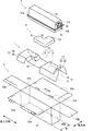
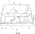
- the buffer member 1 As shown in FIG. 1, the buffer member 1 according to an embodiment of the present invention is interposed between a packaging box 4 and a toner cartridge 5 as a first packaged object, and a second packaged object. As a waste toner collection bottle 6 is held.
- the longitudinal direction and the lateral direction of the buffer member 1 and the packaging box 4 in FIG. 1 are the length direction and the width direction of the cushion member 1 and the packaging box 4.
- the toner cartridge 5 has a substantially rectangular parallelepiped main body 51.
- One end surface 51a in the length direction of the main body 51 has a relatively strong structure with few protrusions and movable parts, but the other end surface 51b has a relatively strong structure when mounted on the image forming apparatus.
- a movable piece such as a fixed piece 52 connected to the developing device, a connecting gear 53, a mounting lever 54 for rotating the connecting gear 53, or a projection is provided.
- the collection bottle 6 is a container having a small thickness, and has a bottom portion 61 having a wide width and an upper portion 62 having a narrower width than the bottom portion 61.
- a connection port 63 connected to the waste toner discharge port of the image forming apparatus is formed in the upper part 62.
- the packaging box 4 includes a rectangular bottom plate 41, a pair of long side plates 42 a erected from a pair of long sides of the bottom plate 41, and a pair of short side plates 42 b erected from a pair of short sides of the bottom plate 41.
- An outer flap 43a is connected to the pair of long side plates 42a via a fold line
- an inner flap 43b is connected to the pair of short side plates 42b via a fold line.
- the width of the bottom plate 41 is W1.
- FIG. 2 is a development view of the buffer member
- FIG. 3 is a perspective view of the buffer member.
- the vertical direction and the horizontal direction indicate the vertical direction and the horizontal direction in FIG.
- the shock-absorbing member 1 is assembled by forming a folding line or a slit in a substantially rectangular packaging material 9 (for example, corrugated cardboard) and bending it at each folding line.
- a substantially rectangular packaging material 9 for example, corrugated cardboard
- the packaging material 9 includes a substantially rectangular mounting portion 10 and first leg portions 11 connected to both end portions of both side edges of the mounting portion 10 via folding lines, respectively.
- the second leg part 12 and the clamping part 13 provided continuously to the first leg part 11.
- the mounting portion 10 includes a first end 15 on one end side (right end side in FIG. 2) in the length direction, a second end portion 16 on the other end side (left end side in FIG. 2), A central portion 17 between the end portion 15 and the second end portion 16.
- the first end portion 15 and the second end portion 16 have substantially the same length, and have a width W2 that is shorter than the width W1 of the bottom plate 41 of the packaging box 4.
- the center portion 17 has a length longer than that of the first end portion 15 and the second end portion 16 and has a width equal to the width W1 of the bottom plate 41 of the packaging box 4.
- a notch 19 is formed at the edge of the first end portion 15.
- the cutout 19 is cut out in a rectangular shape from a portion shifted from the center of the edge in the width direction (upward portion in FIG. 2) toward the central portion 17 (left side in FIG. 2).
- a mountain fold line 21 extending in the width direction is formed between the center portion 17 and the first end portion 15.
- a valley fold line 22 extending in the width direction is formed in the vicinity of the mountain fold line 21.
- the distance between the mountain fold line 21 and the valley fold line 22 is D1.
- a longitudinal slit 23 extending in the length direction is formed in the center portion 17 from the boundary between the second end portion 16 and the center portion 17 to a little before the center in the length direction of the center portion 17.
- the vertical slit 23 is formed at a position shifted from the center in the width direction of the central portion 17 (a slightly lower position in FIG. 2).
- a mountain fold extending in the width direction between the end of the vertical slit 23 on the second end 16 side (left end in FIG. 2) and one side edge of the central portion 17 (lower edge in FIG. 2).
- a line 24 is formed, and extends in the width direction between the opposite end (the right end in FIG. 2) of the vertical slit 23 and the other side edge (the upper edge in FIG. 2) of the central portion 17.
- a valley fold line 25 is formed. Further, a valley fold line 27 extending in the width direction is formed between the center of the longitudinal slit 23 in the length direction and one side edge (lower edge) of the central portion 17. A mountain fold line 26 extending in the width direction is formed between the center in the length direction and the other side edge (upper edge) of the center portion 17. The distance D1 between the mountain fold line 24 and the valley fold line 27 and the distance D1 between the mountain fold line 26 and the valley fold line 25 are equal to the distance D1 between the mountain fold line 21 and the valley fold line 22. Each corner of the central portion 17 is chamfered obliquely.
- the first leg portion 11 has a pair of rectangular leg pieces 31 having a longer length than the first end portion 15 of the placement portion 10.
- Each leg piece 31 is connected to both side edges of the first end portion 15 via a mountain fold line 32, and is more outward in the length direction than the end edge of the first end portion 15 (right direction in FIG. 2). ).
- the extended part of each leg piece 31 is referred to as an extended piece 31a.
- the width D2 of each leg piece 31 is longer than the distance D1 between the mountain fold line 21 and the valley fold line 22.
- the corners of each leg piece 31 are chamfered in an arc shape.
- the second leg portion 12 has a pair of rectangular leg pieces 35 having the same length as the second end portion 16 of the placement portion 10. Each leg piece 35 is connected to both side edges of the second end portion 16 via a mountain fold line 36. The width D2 of each leg piece 35 is equal to the width D2 of each leg piece 31 of the first leg portion 11. The corners of each leg piece 35 are chamfered in an arc shape.
- the clamping part 13 has a pair of clamping pieces 38 having the same rectangular shape.
- Each sandwiching piece 38 extends inward from the inner side edge of each extending piece 31 a in the first leg portion 11. As shown in FIG. 2, the inner side edge of each clamping piece 38 abuts at the center in the width direction of the first end portion 15. The corners of each clamping piece 38 are chamfered obliquely.
- FIGS. 1 and 3 to 6B A method of packing the toner cartridge 5 and the recovery bottle 6 in the packing box 4 using the buffer member 1 having the above configuration will be described with reference to FIGS. 1 and 3 to 6B.
- 3 is a perspective view of the folded cushioning member as seen from above
- FIG. 4 is a perspective view of the packaging box as seen from above during the packaging process
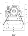
- FIGS. 5, 6A and 6B are toners packed in the packaging box.
- FIGS. 5A and 5B are diagrams showing an end of the cartridge
- FIG. 5 is a front view
- FIG. 6A is a view from the left side
- FIG. 6B is a view from the right side.
- the inner flaps 43b are bent inward so as to overlap the respective short side plates 42b.
- the cushioning member 1 is formed by bending the packing material 9 shown in FIG.
- the mountain fold lines 21, 24, and 26 formed in the central portion 17 of the placement unit 10 are mountain-folded, and the valley fold lines 22, 25, and 27 are valley-folded.
- an L-shaped recess 39 is formed in the central portion 17 that is opposite in the left-right direction in plan view.
- each clamping piece 38 of the clamping portion 13 extended to the extending piece 31 a of each leg piece 31 is cut in an upward direction opposite to the bending direction of each leg piece 31. woken up.
- the buffer member 1 formed in this way is installed on the bottom plate 41 of the packing box 4.
- the width W2 of the first end portion 15 and the second end portion 16 of the mounting portion 10 where the first leg portion 11 and the second leg portion 12 are connected is the bottom plate of the packaging box 4.
- the leg pieces 31 and 35 of the leg portions 11 and 12 are bent at an obtuse angle with respect to the first end portion 15 and the second end portion 16, respectively.
- the lower ends 31b and 35b of each leg piece 31 and 35 are latched by the corner
- each sandwiching piece 38 of the sandwiching portion 13 is also inclined in a letter C shape together with each leg piece 31. Moreover, since the inner flap 43b bent so that it may overlap with the short side board 42b is interposed between the both ends edge of the longitudinal direction of the buffer member 1 and each short side board 42b of the packaging box 4, the buffer member 1 The movement in the longitudinal direction is restricted.
- the toner cartridge 5 is placed on the placement portion 10.
- the end surface 51b of the toner cartridge 5 on the side where the connecting gear 53 and the mounting lever 54 are provided is directed to the first end portion 15 side.
- the connecting gear 53 is arranged between the opposing clamping pieces 38 of the clamping part 13, and the mounting lever 54 is provided in the notch 19 formed in the first end 15 of the mounting part 10.
- the end surface 51b of the main body 51 of the toner cartridge 5 is brought into contact with each sandwiching piece 38, as shown in FIGS.
- a space is formed between each end piece 51b of the main body 51 of the toner cartridge 5 and the inner flap 43b of the packing box 4 so that the holding pieces 38 are sandwiched.
- the lever 54 and the like are accommodated. Further, as shown in FIG.
- each clamping piece 38 is in contact with the protrusion provided on the end surface 51 b of the main body 51, and thus the main body 51 in the width direction. Movement is restricted.
- the opposing surface of each clamping piece 38 includes the upper edge of each clamping piece 38.
- the toner cartridge 5 is urged toward the clamping unit 13 by a part of the bent inner flap 43b. Thereby, the movement of the toner cartridge 5 in the length direction is restricted by each sandwiching piece 38 and the inner flap 43b.
- the leg pieces 31 and 35 are biased in the opening direction by the downward force applied from the toner cartridge 5 to the placement unit 10, and each leg piece 31 and 35 are maintained in a C-shaped posture. That is, the leg pieces 31 and 35 are not bent inward. Finally, the outer flap 43a is closed and the packaging box 4 is sealed.
- the toner cartridge 5 can be placed above the bottom plate 41 of the packaging box 4 by simply bending the first leg portion 11 and the second leg portion 12. It can be supported stably. Further, movement of the toner cartridge 5 is regulated by the clamping unit 13, and the fixing piece 52, the connecting gear 53, and the mounting lever 54 provided on the end surface 51 b of the main body 51 of the toner cartridge 5 are protected by the clamping unit 13. Can be. Therefore, the toner cartridge 5 can be reliably protected from dropping and impact. Moreover, the structure of the buffer member 1 becomes simple and the amount of corrugated paper used can be reduced.
- the downward force applied to the mounting portion 10 from the toner cartridge 5 stably maintains the cross-sectional posture of each leg piece 31, 35, so that the toner cartridge 5 is positioned above the bottom plate 41 of the packaging box 4.
- the width of the central portion 17 is equal to the width W1 of the bottom plate 41 of the packaging box 4, and the width W2 of the first end portion 15 and the second end portion 16 is narrower than the width W1 of the bottom plate 41. Can be easily inserted into the packing box 4 and can be stably placed in the packing box 4.
- the collection bottle 6 when the collection bottle 6 that is the second packaged item is present, the collection bottle 6 can be held in the recess 39 in an immovable manner without affecting the support of the toner cartridge 5. Further, since the recess 39 is formed in the space between the mounting portion 10 and the bottom plate 41 of the packaging box 4, that is, the space for buffering the toner cartridge 5, the space in the packaging box 4 is effectively utilized. it can. Further, since the support of the recovery bottle 6 can be shared by the buffer member 1, a dedicated part for holding the recovery bottle 6 becomes unnecessary, and the amount of corrugated paper used can be further reduced.
- the first leg portion 11 and the second leg portion 12 are connected to the first end portion 15 and the second end portion 16 of the mounting portion 10 and are not provided in the central portion 17. Therefore, the amount of corrugated paper used can be further reduced.
- the toner cartridge 5 includes the first end portion 15 of the mounting portion 10, the second end portion 16, and a part of the central portion 17 continuous to the second end portion 16. Both ends in the length direction are supported by the toner cartridge 5, but since the toner cartridge 5 has rigidity in the length direction, it is supported by the buffer member 1 with no problem in strength.
- the buffer member 1 can be used in common.
- the concave portion 39 that accommodates the collection bottle 6 is formed in the central portion 17 of the mounting portion 10 of the buffer member 1. However, when the collection bottle 6 does not exist, it is not necessary to form the concave portion 39. .
- one leg portion composed of a pair of leg pieces may be provided on the mounting portion 10. Also in this case, a pair of clamping parts cut and raised in the direction opposite to the bending direction can be formed at the end of each leg piece.
- the case of the toner cartridge 5 which is an exchange member attached to the image forming apparatus has been described as an object to be packed, but the present invention can also be used for other exchange members such as a developing unit and a drum unit. .
- a movable portion or a projection portion connected to another unit or a driving mechanism is provided at one end portion like the toner cartridge 5. It is preferable to protect the movable part and the protruding part.
- a pair of sandwiching parts 13 can be formed on both the first leg part 11 and the second leg part 12. .
- an instruction manual etc. can also be accommodated in the recessed part 39.
Landscapes
- Engineering & Computer Science (AREA)
- Mechanical Engineering (AREA)
- Life Sciences & Earth Sciences (AREA)
- Manufacturing & Machinery (AREA)
- Sustainable Development (AREA)
- Computer Vision & Pattern Recognition (AREA)
- Physics & Mathematics (AREA)
- General Physics & Mathematics (AREA)
- Buffer Packaging (AREA)
- Cartons (AREA)
Abstract
Description
Claims (10)
- 底板と該底板の周縁から立設された側板とを有する梱包箱と第1被梱包物との間に介装される緩衝部材であって、
前記第1被梱包物が載置される載置部と、
前記載置部の対向する一対の辺に折り曲げ線を介して連接される少なくとも一対の脚片と、
を備え、
前記一対の脚片は、前記載置部に対して鈍角を成すように前記折り曲げ線に沿って下方に折り曲げられた姿勢で、その下端が前記梱包箱の前記底板と前記側板とが交わる境界に係止されることを特徴とする緩衝部材。 - 前記載置部は略長方形状を有し、
長手方向の一端側に設けられた第1の端部と、
他端側に設けられた第2の端部と、
前記第1の端部と前記第2の端部との間に設けられた中央部と、を備え、
前記第1被梱包物は、前記第1の端部と前記第2の端部に載置されることを特徴とする請求項1に記載の緩衝部材。 - 前記載置部の前記中央部には、下方に折り曲げられることで第2被梱包物を収容するための凹部が形成されることを特徴とする請求項2に記載の緩衝部材。
- 前記第1の端部及び前記第2の端部にそれぞれ前記一対の脚片が連接されていることを特徴とする請求項2に記載の緩衝部材。
- 前記長手方向に直交する方向において、前記中央部の幅は前記梱包箱の前記底板の幅と等しく、前記第1の端部と前記第2の端部の幅は前記中央部の幅よりも狭いことを特徴とする請求項2に記載の緩衝部材。
- 少なくとも1つの前記一対の脚片は、該一対の脚片が前記折り曲げ線に沿って下方に折り曲げられた際に、該折り曲げ方向と反対方向に切り起こされる一対の挟持部を備えることを特徴とする請求項1に記載の緩衝部材。
- 前記一対の挟持部は、対向する面のそれぞれに前記第1被梱包物が当接するように設けられていることを特徴とする請求項6に記載の緩衝部材。
- 前記第1被梱包物は、画像形成装置に装着されるトナーカートリッジであり、
前記一対の脚片が前記折り曲げ線に沿って下方に折り曲げられた際に、該折り曲げ方向と反対方向に切り起こされて形成される一対の挟持部を備え、前記トナーカートリッジの前記長手方向端面と該長手方向端面と対向する前記梱包箱の前記側板との間に、前記一対の挟持部を挟んだ空間が形成され、該空間に前記トナーカートリッジの前記長手方向端面に設けられた可動部及び突起部が収容されることを特徴とする請求項1に記載の緩衝部材。 - 前記載置部は長方形状を有し、前記一対の脚片は、前記載置部の対向する一対の長辺に前記折り曲げ線を介して連接されることを特徴とする請求項1に記載の緩衝部材。
- 前記梱包箱は、前記載置部の長手方向に対向する一対の前記側板のそれぞれの上縁に折り曲げ線を介して連接されて、それぞれ対応する前記側板に重なるように前記折り曲げ線で内側に折り曲げられるフラップを有することを特徴とする請求項1に記載の緩衝部材。
Priority Applications (2)
| Application Number | Priority Date | Filing Date | Title |
|---|---|---|---|
| US15/324,070 US10294003B2 (en) | 2014-09-22 | 2015-07-08 | Buffering member |
| JP2016549996A JP6327352B2 (ja) | 2014-09-22 | 2015-07-08 | 緩衝部材 |
Applications Claiming Priority (2)
| Application Number | Priority Date | Filing Date | Title |
|---|---|---|---|
| JP2014-192194 | 2014-09-22 | ||
| JP2014192194 | 2014-09-22 |
Publications (1)
| Publication Number | Publication Date |
|---|---|
| WO2016047239A1 true WO2016047239A1 (ja) | 2016-03-31 |
Family
ID=55580776
Family Applications (1)
| Application Number | Title | Priority Date | Filing Date |
|---|---|---|---|
| PCT/JP2015/069663 Ceased WO2016047239A1 (ja) | 2014-09-22 | 2015-07-08 | 緩衝部材 |
Country Status (3)
| Country | Link |
|---|---|
| US (1) | US10294003B2 (ja) |
| JP (1) | JP6327352B2 (ja) |
| WO (1) | WO2016047239A1 (ja) |
Cited By (4)
| Publication number | Priority date | Publication date | Assignee | Title |
|---|---|---|---|---|
| JP2017057011A (ja) * | 2015-09-16 | 2017-03-23 | 京セラドキュメントソリューションズ株式会社 | 梱包部材 |
| JP2018052548A (ja) * | 2016-09-29 | 2018-04-05 | キヤノン株式会社 | 緩衝材 |
| JP2022015472A (ja) * | 2020-07-09 | 2022-01-21 | ダイキン工業株式会社 | 梱包材及び梱包方法 |
| CN114313532A (zh) * | 2022-01-19 | 2022-04-12 | 北京观云科技有限公司 | 包装盒 |
Families Citing this family (2)
| Publication number | Priority date | Publication date | Assignee | Title |
|---|---|---|---|---|
| JP5811488B1 (ja) * | 2015-04-17 | 2015-11-11 | 株式会社Groundstar | 包装用容器 |
| JP7021476B2 (ja) * | 2017-08-31 | 2022-02-17 | 京セラドキュメントソリューションズ株式会社 | 梱包ケース |
Citations (4)
| Publication number | Priority date | Publication date | Assignee | Title |
|---|---|---|---|---|
| JPS52149873U (ja) * | 1976-05-06 | 1977-11-14 | ||
| JPS571150U (ja) * | 1980-06-03 | 1982-01-06 | ||
| JPS58192275U (ja) * | 1982-06-16 | 1983-12-21 | 松下電器産業株式会社 | シエ−ドの包装装置 |
| JP2008110772A (ja) * | 2006-10-30 | 2008-05-15 | Icom Inc | 梱包材および梱包方法 |
Family Cites Families (9)
| Publication number | Priority date | Publication date | Assignee | Title |
|---|---|---|---|---|
| US2134375A (en) * | 1938-01-08 | 1938-10-25 | Western Electric Co | Package |
| US3017018A (en) * | 1959-05-12 | 1962-01-16 | Tung Sol Electric Inc | Shipping and display carton |
| US5676245A (en) * | 1996-04-02 | 1997-10-14 | Jones; William Charles | Article packaging kit, system and method |
| US6308828B1 (en) * | 2000-05-26 | 2001-10-30 | Emerging Technologies Trust | Package kit and method |
| JP4242228B2 (ja) | 2003-07-25 | 2009-03-25 | 京セラミタ株式会社 | 梱包箱 |
| JP2008030832A (ja) | 2006-07-31 | 2008-02-14 | Kyocera Mita Corp | 梱包部材 |
| TWI310357B (en) * | 2006-09-27 | 2009-06-01 | Quanta Comp Inc | Stereoscopic inner spacer |
| US8627958B2 (en) * | 2008-07-02 | 2014-01-14 | Clearpak, Llc | Suspension packaging system |
| JP2010095275A (ja) * | 2008-10-16 | 2010-04-30 | Funai Electric Co Ltd | 電子機器梱包装置 |
-
2015
- 2015-07-08 US US15/324,070 patent/US10294003B2/en active Active
- 2015-07-08 JP JP2016549996A patent/JP6327352B2/ja not_active Expired - Fee Related
- 2015-07-08 WO PCT/JP2015/069663 patent/WO2016047239A1/ja not_active Ceased
Patent Citations (4)
| Publication number | Priority date | Publication date | Assignee | Title |
|---|---|---|---|---|
| JPS52149873U (ja) * | 1976-05-06 | 1977-11-14 | ||
| JPS571150U (ja) * | 1980-06-03 | 1982-01-06 | ||
| JPS58192275U (ja) * | 1982-06-16 | 1983-12-21 | 松下電器産業株式会社 | シエ−ドの包装装置 |
| JP2008110772A (ja) * | 2006-10-30 | 2008-05-15 | Icom Inc | 梱包材および梱包方法 |
Cited By (5)
| Publication number | Priority date | Publication date | Assignee | Title |
|---|---|---|---|---|
| JP2017057011A (ja) * | 2015-09-16 | 2017-03-23 | 京セラドキュメントソリューションズ株式会社 | 梱包部材 |
| JP2018052548A (ja) * | 2016-09-29 | 2018-04-05 | キヤノン株式会社 | 緩衝材 |
| JP2022015472A (ja) * | 2020-07-09 | 2022-01-21 | ダイキン工業株式会社 | 梱包材及び梱包方法 |
| JP7096506B2 (ja) | 2020-07-09 | 2022-07-06 | ダイキン工業株式会社 | 梱包材及び梱包方法 |
| CN114313532A (zh) * | 2022-01-19 | 2022-04-12 | 北京观云科技有限公司 | 包装盒 |
Also Published As
| Publication number | Publication date |
|---|---|
| US20170203902A1 (en) | 2017-07-20 |
| JPWO2016047239A1 (ja) | 2017-04-27 |
| US10294003B2 (en) | 2019-05-21 |
| JP6327352B2 (ja) | 2018-05-23 |
Similar Documents
| Publication | Publication Date | Title |
|---|---|---|
| JP6327352B2 (ja) | 緩衝部材 | |
| US8944312B2 (en) | Packing box | |
| JP2016113212A (ja) | 包装箱 | |
| JP6033166B2 (ja) | 包装ケース | |
| JP6035283B2 (ja) | 梱包箱 | |
| JP6099351B2 (ja) | 瓶保持体及び補助部材 | |
| JP2008018979A (ja) | 空中梱包具 | |
| JP6669007B2 (ja) | 梱包部材 | |
| JP2008201450A (ja) | 板状体の梱包材及びそれを用いた梱包体 | |
| JP2007106467A (ja) | 空中梱包具 | |
| JP5091622B2 (ja) | 支持部材 | |
| JPH09301351A (ja) | 包装箱 | |
| JP6291888B2 (ja) | 梱包体 | |
| JP4760817B2 (ja) | 梱包用緩衝装置 | |
| JP6324158B2 (ja) | 表示装置の梱包構造 | |
| JP6175563B2 (ja) | 梱包箱 | |
| JP6057872B2 (ja) | 包装装置 | |
| JP2009107676A (ja) | 支持部材 | |
| JP2936367B2 (ja) | 梱包用保持部材 | |
| JP7204372B2 (ja) | 梱包体 | |
| JP5020013B2 (ja) | 梱包用スペーサ | |
| JP5372214B2 (ja) | 板状体の梱包材及びそれを用いた梱包体 | |
| JP5374988B2 (ja) | ユニット梱包箱 | |
| JP6033168B2 (ja) | 緩衝部材 | |
| JP2013116771A (ja) | ケース |
Legal Events
| Date | Code | Title | Description |
|---|---|---|---|
| 121 | Ep: the epo has been informed by wipo that ep was designated in this application |
Ref document number: 15843504 Country of ref document: EP Kind code of ref document: A1 |
|
| ENP | Entry into the national phase |
Ref document number: 2016549996 Country of ref document: JP Kind code of ref document: A |
|
| WWE | Wipo information: entry into national phase |
Ref document number: 15324070 Country of ref document: US |
|
| NENP | Non-entry into the national phase |
Ref country code: DE |
|
| 122 | Ep: pct application non-entry in european phase |
Ref document number: 15843504 Country of ref document: EP Kind code of ref document: A1 |