WO2016042816A1 - 遠心圧縮機 - Google Patents
遠心圧縮機 Download PDFInfo
- Publication number
- WO2016042816A1 WO2016042816A1 PCT/JP2015/059342 JP2015059342W WO2016042816A1 WO 2016042816 A1 WO2016042816 A1 WO 2016042816A1 JP 2015059342 W JP2015059342 W JP 2015059342W WO 2016042816 A1 WO2016042816 A1 WO 2016042816A1
- Authority
- WO
- WIPO (PCT)
- Prior art keywords
- impeller
- flow path
- fluid
- centrifugal compressor
- return
- Prior art date
- Legal status (The legal status is an assumption and is not a legal conclusion. Google has not performed a legal analysis and makes no representation as to the accuracy of the status listed.)
- Ceased
Links
Images
Classifications
-
- F—MECHANICAL ENGINEERING; LIGHTING; HEATING; WEAPONS; BLASTING
- F04—POSITIVE - DISPLACEMENT MACHINES FOR LIQUIDS; PUMPS FOR LIQUIDS OR ELASTIC FLUIDS
- F04D—NON-POSITIVE-DISPLACEMENT PUMPS
- F04D29/00—Details, component parts, or accessories
- F04D29/40—Casings; Connections of working fluid
- F04D29/42—Casings; Connections of working fluid for radial or helico-centrifugal pumps
- F04D29/44—Fluid-guiding means, e.g. diffusers
- F04D29/441—Fluid-guiding means, e.g. diffusers especially adapted for elastic fluid pumps
- F04D29/444—Bladed diffusers
-
- F—MECHANICAL ENGINEERING; LIGHTING; HEATING; WEAPONS; BLASTING
- F04—POSITIVE - DISPLACEMENT MACHINES FOR LIQUIDS; PUMPS FOR LIQUIDS OR ELASTIC FLUIDS
- F04D—NON-POSITIVE-DISPLACEMENT PUMPS
- F04D17/00—Radial-flow pumps, e.g. centrifugal pumps; Helico-centrifugal pumps
- F04D17/08—Centrifugal pumps
- F04D17/16—Centrifugal pumps for displacing without appreciable compression
- F04D17/165—Axial entry and discharge
-
- F—MECHANICAL ENGINEERING; LIGHTING; HEATING; WEAPONS; BLASTING
- F04—POSITIVE - DISPLACEMENT MACHINES FOR LIQUIDS; PUMPS FOR LIQUIDS OR ELASTIC FLUIDS
- F04D—NON-POSITIVE-DISPLACEMENT PUMPS
- F04D29/00—Details, component parts, or accessories
- F04D29/05—Shafts or bearings, or assemblies thereof, specially adapted for elastic fluid pumps
- F04D29/056—Bearings
- F04D29/059—Roller bearings
-
- F—MECHANICAL ENGINEERING; LIGHTING; HEATING; WEAPONS; BLASTING
- F04—POSITIVE - DISPLACEMENT MACHINES FOR LIQUIDS; PUMPS FOR LIQUIDS OR ELASTIC FLUIDS
- F04D—NON-POSITIVE-DISPLACEMENT PUMPS
- F04D29/00—Details, component parts, or accessories
- F04D29/26—Rotors specially for elastic fluids
- F04D29/266—Rotors specially for elastic fluids mounting compressor rotors on shafts
-
- F—MECHANICAL ENGINEERING; LIGHTING; HEATING; WEAPONS; BLASTING
- F04—POSITIVE - DISPLACEMENT MACHINES FOR LIQUIDS; PUMPS FOR LIQUIDS OR ELASTIC FLUIDS
- F04D—NON-POSITIVE-DISPLACEMENT PUMPS
- F04D29/00—Details, component parts, or accessories
- F04D29/26—Rotors specially for elastic fluids
- F04D29/28—Rotors specially for elastic fluids for centrifugal or helico-centrifugal pumps for radial-flow or helico-centrifugal pumps
- F04D29/284—Rotors specially for elastic fluids for centrifugal or helico-centrifugal pumps for radial-flow or helico-centrifugal pumps for compressors
-
- F—MECHANICAL ENGINEERING; LIGHTING; HEATING; WEAPONS; BLASTING
- F04—POSITIVE - DISPLACEMENT MACHINES FOR LIQUIDS; PUMPS FOR LIQUIDS OR ELASTIC FLUIDS
- F04D—NON-POSITIVE-DISPLACEMENT PUMPS
- F04D29/00—Details, component parts, or accessories
- F04D29/40—Casings; Connections of working fluid
- F04D29/42—Casings; Connections of working fluid for radial or helico-centrifugal pumps
- F04D29/4206—Casings; Connections of working fluid for radial or helico-centrifugal pumps especially adapted for elastic fluid pumps
Definitions
- the present invention relates to a centrifugal compressor.
- centrifugal compressors are used in petrochemical plants and natural gas plants.
- kinetic energy is given to the fluid by rotation of the impeller, and pressure is increased by centrifugal force by blowing the fluid outward in the radial direction.
- a scroll flow path formed in a spiral shape in the circumferential direction is provided on the outlet side of the impeller, and the fluid blown from the impeller is discharged to the outside of the casing through the scroll flow path.
- the configuration is known (see, for example, Patent Document 1).
- the scroll flow path is formed, for example, so that the cross-sectional area gradually increases toward the outlet in the circumferential direction, and fluid pressure loss is caused by circulating the scroll flow path using the circumferential velocity component of the fluid. We are trying to reduce it.
- this type of centrifugal compressor has a tendency to be subdivided in applications.
- a centrifugal compressor having a low head and a large discharge flow rate is desired.
- the radial velocity component becomes larger than the circumferential velocity component.
- the swirl flow in the meridional section of the scroll flow path is caused by the increased radial velocity component at the scroll flow path inlet that is the diffuser outlet as the impeller has a larger flow rate. growing. Accordingly, there is a problem that smooth circulation in the scroll channel is hindered, the pressure loss coefficient of the scroll channel is increased, and the efficiency of the centrifugal compressor is lowered.
- the present invention has been made in view of such circumstances, and an object thereof is to provide a centrifugal compressor that suppresses the pressure loss of the fluid blown out from the impeller and improves the efficiency.
- a centrifugal compressor includes a rotating shaft that is rotatably supported by a casing, and a fluid that is provided on the rotating shaft and sucks fluid from the suction port.
- An impeller that blows in the radial direction, a return channel that reverses the fluid blown from the impeller toward the rotation axis, and a fluid that is located on the axis of the rotation axis and passes through the return channel is discharged in a direction along the axis And a discharge port.
- the return flow path that reverses the fluid blown from the impeller toward the rotation axis and the fluid that is located on the axis of the rotation axis and passes through the return flow path are discharged in a direction along the axis.
- the scroll channel has a larger pressure loss coefficient than the return channel, and the difference increases as the flow coefficient increases. For this reason, the efficiency of the centrifugal compressor can be greatly improved by changing the impeller having a large flow coefficient from the scroll flow path to the return flow path.
- the discharge port is located on the axis of the rotation axis and discharges the fluid that has passed through the return channel in the direction along the axis, so that the fluid that has passed through the return channel discharges without interfering with each other. Can do.
- a bearing that supports the rotating shaft may be provided, and the impeller may be provided on the shaft end side closer to the discharge port than the bearing.
- the impeller is supported on the rotating shaft in a so-called cantilever (also referred to as overhang) state. For this reason, it is not necessary to provide a sealing member between the impeller and the discharge port, and the structure can be simplified.
- the suction port is preferably provided in a direction perpendicular to the axial direction of the rotation shaft. According to this structure, since it can arrange
- the return flow path is preferably provided with a return vane on the outlet side of the return flow path. Since the return vane has a relatively small pressure loss coefficient compared to the scroll flow path, for example, when the flow rate is increased, the efficiency of the centrifugal compressor can be further improved.
- a single impeller may be provided to perform single-stage compression.
- the return flow path that inverts the fluid blown from the impeller toward the rotation axis and the fluid that is located on the axis of the rotation axis and passes through the return flow path are discharged in a direction along the axis.
- the scroll channel has a larger pressure loss coefficient than the return channel, and the difference increases as the flow coefficient increases. For this reason, the efficiency of the centrifugal compressor can be greatly improved by changing the impeller having a large flow coefficient from the scroll flow path to the return flow path.
- the discharge port is located on the axis of the rotation axis and discharges the fluid that has passed through the return channel in the direction along the axis, so that the fluid that has passed through the return channel discharges without interfering with each other. Can do.
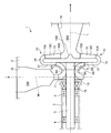
- FIG. 1 is a longitudinal sectional view of a centrifugal compressor according to this embodiment.
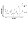
- FIG. 2 is a graph comparing the relationship between the flow coefficient and the pressure loss coefficient in the scroll flow path and the return flow path.
- FIG. 1 is a longitudinal sectional view of a centrifugal compressor according to this embodiment.
- the centrifugal compressor 1 is, for example, a gas or air having a low flow rate (for example, a pressure ratio of about 1.05) and a large flow rate (for example, about 5.0 m 3 / s) in a predetermined pressure vessel of a chemical plant. Used as a compressor for supplying fluid.
- the centrifugal compressor 1 rotates around its axis L through bearings 4 and 4 in a casing 2 formed by combining a plurality of parts and a space 3 formed in the casing 2.
- a rotary shaft 5 that is supported is provided, and a closed-type impeller 6 that is fixed to the rotary shaft 5 and is provided to rotate integrally with the rotary shaft 5.
- the impeller 6 is fixed to the shaft end portion 5A of the rotary shaft 5 located outside the bearings 4 and 4 (upper side in FIG. 1). For this reason, the impeller 6 is supported on the rotating shaft 5 in a so-called cantilever state (also referred to as an overhang).
- the impeller 6 is not limited to the closed type in which the wing portion and the shroud portion are integrated as in the present embodiment, but may be an open type without the shroud portion.
- the centrifugal compressor 1 is a single-stage centrifugal compressor including a single impeller 6.
- the centrifugal compressor 1 is driven by a driving device (not shown) and the impeller 6 is rotated to rotate a fluid such as gas or air to be compressed through a suction port 10 provided in the casing 2. Is sucked.
- the suction port 10 opens in a direction along a perpendicular line M perpendicular to the axis L of the rotation shaft 5.
- a suction passage 11 is connected to the suction port 10 via a suction space 10A formed in the casing 2, and the suction passage 11 bends along the axis L direction (axial direction) of the rotary shaft 5.
- the opening is opposed to the suction port 6A of the impeller 6.
- the centrifugal compressor 1 also includes a vaneless diffuser 12 and a return flow path 13 that are provided radially with respect to the axis L of the rotating shaft 5 on the outlet 6B side of the impeller 6.
- the vane-less diffuser 12 constitutes a flow path that converts the kinetic energy of the fluid to which the centrifugal force is applied by the impeller 6 into pressure energy and sends it out.
- the return flow path 13 is a flow path that reverses the direction of the fluid blown radially outward by the impeller 6 and the vaneless diffuser 12 toward the rotation shaft 5, that is, radially inward, and the vaneless diffuser 12.
- a return bend 14 and a return flow path 15 are provided.
- the outlet 15B of the return flow path 15 is connected to a discharge space 16A provided in the casing 2, respectively.
- the discharge space 16 ⁇ / b> A is located on the axis L of the rotating shaft 5, and the discharge port 16 is opened so as to discharge the fluid along the axis L.
- the return channel 15 is formed with a gradually increasing channel area (cross-sectional area) from the inlet 15 ⁇ / b> A to the outlet 15 ⁇ / b> B of the return channel 15, and restricts the flow of fluid inside the return channel 15.
- a return vane 15C is provided.
- the fluid that passes through the vaneless diffuser 12 and flows into the return flow path 13 has a radial velocity component and a circumferential velocity component.
- the radial speed component tends to be larger than the circumferential speed component, and the return vane 15C flows into the return flow path 13 (return flow path 15).
- the flow of the fluid is regulated so as to suppress the circumferential velocity component. For this reason, a fluid having a radial velocity component mainly flows at the outlet 15B of the return flow path 15, and the spiral speed component is not discarded unlike the outlet of the scroll flow path.
- the pressure loss of the fluid in the return flow path 13 can be suppressed.
- each return channel 15 flows into the discharge space 16A and is mixed in the discharge space 16A.
- a guide protrusion 16B that protrudes toward the discharge port 16 on the axis L is provided.
- the guide protrusion 16B guides the flow of the fluid flowing into the discharge space 16A by changing it in the direction of the axis L.
- the fluid discharged from the discharge port 16 is sent to a discharge pipe (not shown).
- a shaft seal 18 and a balance piston 19 that maintain airtightness are disposed between the bearing 4 and the suction flow path 11.
- the shaft seal 18 prevents communication between the above-described space 3 and a path through which fluid flows including the impeller 6 and the like.
- the centrifugal compressor 1 includes a return flow path 13 that reverses the fluid blown from the impeller 6 toward the axis L of the rotating shaft 5.
- the fluid tends to have a larger radial velocity component than the circumferential velocity component, and the return provided on the outlet side of the return flow channel 13 (return flow channel 15).
- the vane 15 ⁇ / b> C regulates the flow of fluid so as to suppress the circumferential velocity component of the fluid flowing into the return flow path 15. For this reason, a fluid having a radial velocity component mainly flows at the outlet 15B of the return flow path 15.
- the centrifugal compressor 1 includes the discharge port 16 that is located on the axis L of the rotary shaft 5 and discharges the fluid that has passed through the return flow path 13 in the direction along the axis L.
- the fluid having the radial velocity component that has passed through the flow path 13 is mixed without interfering with each other, and can be smoothly discharged from the discharge port 16.
- the centrifugal compressor 1 includes the bearings 4 and 4 that support the rotating shaft 5, and the impeller 6 is provided at the shaft end portion 5 ⁇ / b> A closer to the discharge port 16 than the bearing 4. Therefore, the impeller 6 is supported on the rotating shaft 5 in a so-called cantilever state. For this reason, it is not necessary to provide a sealing member between the impeller 6 and the discharge port 16, and the structure of the centrifugal compressor 1 can be simplified.
- the suction inlet 10 is provided toward the perpendicular M direction orthogonal to the axis L direction of the rotating shaft 5, the suction inlet 10 is provided in the casing 2 with the bearing 4 of the rotating shaft 5, etc. It can arrange
- the return flow path 13 since the return flow path 13 includes the return vane 15C in the return flow path 15 arranged on the outlet side of the return flow path 13, the return vane 15C Of the fluid flowing into the flow path 15), the flow of the fluid is regulated so as to suppress the circumferential velocity component. For this reason, a fluid having a radial velocity component mainly flows at the outlet 15B of the return flow path 15. Further, since the return vane 15C has a relatively small pressure loss coefficient as compared with the case where the scroll flow path is provided, the efficiency of the centrifugal compressor 1 can be further improved when the flow rate is increased. .
- FIG. 2 is a graph comparing the relationship between the flow coefficient and the pressure loss coefficient in the scroll flow path and the return flow path.
- three types of impellers A to C having different flow coefficients ⁇ are used, and these impellers A to C are provided with a conventional centrifugal compressor having a scroll flow path and a return flow path 13 in this embodiment.
- the pressure loss coefficient ⁇ is measured when each centrifugal compressor is operated.
- the flow coefficient ⁇ increases in the order of impeller A, impeller B, and impeller C.
- the pressure loss coefficient ⁇ increases as the impeller C has a larger flow coefficient ⁇ (see the one-dot chain line in FIG. 2).
- the fluid blown from the impeller has a radial velocity component and a circumferential velocity component, and the radial velocity component increases as the flow rate increases.
- the scroll channel is a channel formed in a spiral shape in the circumferential direction
- the fluid of the circumferential velocity component flows smoothly in the scroll channel, but the fluid of the radial velocity component flows in the circumferential direction. Inhibits.
- flow coefficient ⁇ flow coefficient
- the fluid of the radial velocity component tends to flow smoothly through the return flow path 13.
- the pressure loss coefficient ⁇ is substantially the same regardless of the magnitude of the flow coefficient ⁇ .
- the return flow path 15 on the outlet side of the return flow path 13 is provided with a return vane 15C, and the return vane 15C regulates the flow of the circumferential speed component, so that the return flow path 13 mainly has a radial speed. A fluid having components flows out.
- the return flow path 13 does not obstruct the flow caused by the swirl flow in the meridional section like the scroll flow path, and does not discard the swirl velocity component at the exit of the scroll flow path, the pressure when flowing through the return flow path 13 Loss can be suppressed, and the efficiency of the centrifugal compressor 1 can be improved.
- the centrifugal compressor 1 has a configuration in which a drive device that drives the rotating shaft 5 is separately provided, but a structure in which an electric motor as a drive device and a compressor are integrally provided in a casing and sealed. It is also good. According to this structure, for example, since the electric motor and the compressor are integrally provided in the casing and the casing is sealed, the seal member (see the shaft seal 18 in FIG. 1) is provided between the electric motor and the impeller 6. There is no need to provide it, and the configuration of the centrifugal compressor can be simplified.
- the impeller 6 is provided at the shaft end portion 5A of the rotary shaft 5 in a cantilever support structure.
- the present invention is not limited to this, and the discharge space 16A provided in the impeller 6 and the casing 2 is used. It is good also as a structure which provides the bearing which pivotally supports the rotating shaft 5 in shaft end part 5A between.
- the magnetic bearing is used as the bearing, there is no need to provide a lubricating oil path for supplying lubricating oil to the bearing, and the shaft vibration can be suppressed while the apparatus configuration is simplified.
- route can be ensured, the general bearing to which lubricating oil will be supplied can also be used.
- the single-stage compressor provided with the single impeller 6 in the casing 2 has been described.
- the present invention is not limited to this.
- a plurality of (two or three, etc.) impellers 6 are arranged on the rotating shaft 5, and the outlet channel of the upstream side impeller 6 and the inlet side of the downstream side impeller 6 are returned to the return flow path. 13 may be connected. With this configuration, even in the multistage centrifugal compressor 1, an improvement in efficiency at a large flow rate can be realized.
Landscapes
- Engineering & Computer Science (AREA)
- Mechanical Engineering (AREA)
- General Engineering & Computer Science (AREA)
- Structures Of Non-Positive Displacement Pumps (AREA)
Priority Applications (3)
| Application Number | Priority Date | Filing Date | Title |
|---|---|---|---|
| CN201580044987.XA CN106662120A (zh) | 2014-09-18 | 2015-03-26 | 离心式压缩机 |
| EP15842653.6A EP3196479A1 (en) | 2014-09-18 | 2015-03-26 | Centrifugal compressor |
| US15/504,075 US20180172023A1 (en) | 2014-09-18 | 2015-03-26 | Centrifugal compressor |
Applications Claiming Priority (2)
| Application Number | Priority Date | Filing Date | Title |
|---|---|---|---|
| JP2014190466A JP6289323B2 (ja) | 2014-09-18 | 2014-09-18 | 遠心圧縮機 |
| JP2014-190466 | 2014-09-18 |
Publications (1)
| Publication Number | Publication Date |
|---|---|
| WO2016042816A1 true WO2016042816A1 (ja) | 2016-03-24 |
Family
ID=55532864
Family Applications (1)
| Application Number | Title | Priority Date | Filing Date |
|---|---|---|---|
| PCT/JP2015/059342 Ceased WO2016042816A1 (ja) | 2014-09-18 | 2015-03-26 | 遠心圧縮機 |
Country Status (5)
| Country | Link |
|---|---|
| US (1) | US20180172023A1 (enExample) |
| EP (1) | EP3196479A1 (enExample) |
| JP (1) | JP6289323B2 (enExample) |
| CN (1) | CN106662120A (enExample) |
| WO (1) | WO2016042816A1 (enExample) |
Families Citing this family (2)
| Publication number | Priority date | Publication date | Assignee | Title |
|---|---|---|---|---|
| GB2578760B (en) * | 2018-11-07 | 2021-08-04 | Dyson Technology Ltd | Compressor |
| CN112160939A (zh) * | 2020-11-09 | 2021-01-01 | 珠海格力电器股份有限公司 | 压缩机流道及压缩机 |
Citations (4)
| Publication number | Priority date | Publication date | Assignee | Title |
|---|---|---|---|---|
| US4693669A (en) * | 1985-03-29 | 1987-09-15 | Rogers Sr Leroy K | Supercharger for automobile engines |
| JP2003293995A (ja) * | 2002-04-02 | 2003-10-15 | Mitsubishi Heavy Ind Ltd | 遠心圧縮機及び遠心圧縮機の運転方法 |
| JP2004300929A (ja) * | 2003-03-28 | 2004-10-28 | Tokyo Electric Power Co Inc:The | 多段圧縮機、ヒートポンプ、並びに熱利用装置 |
| JP2011252424A (ja) * | 2010-06-01 | 2011-12-15 | Hitachi Plant Technologies Ltd | ターボ形流体機械 |
Family Cites Families (3)
| Publication number | Priority date | Publication date | Assignee | Title |
|---|---|---|---|---|
| CN1081757C (zh) * | 1996-03-06 | 2002-03-27 | 株式会社日立制作所 | 离心压缩机以及用于离心压缩机的扩压器 |
| JP2002005089A (ja) * | 2000-06-20 | 2002-01-09 | Mitsubishi Heavy Ind Ltd | ターボ形圧縮機及びそれを備えた冷凍装置 |
| JP2011043130A (ja) * | 2009-08-24 | 2011-03-03 | Hitachi Appliances Inc | 遠心圧縮機及び冷凍装置 |
-
2014
- 2014-09-18 JP JP2014190466A patent/JP6289323B2/ja not_active Expired - Fee Related
-
2015
- 2015-03-26 CN CN201580044987.XA patent/CN106662120A/zh active Pending
- 2015-03-26 EP EP15842653.6A patent/EP3196479A1/en not_active Withdrawn
- 2015-03-26 WO PCT/JP2015/059342 patent/WO2016042816A1/ja not_active Ceased
- 2015-03-26 US US15/504,075 patent/US20180172023A1/en not_active Abandoned
Patent Citations (4)
| Publication number | Priority date | Publication date | Assignee | Title |
|---|---|---|---|---|
| US4693669A (en) * | 1985-03-29 | 1987-09-15 | Rogers Sr Leroy K | Supercharger for automobile engines |
| JP2003293995A (ja) * | 2002-04-02 | 2003-10-15 | Mitsubishi Heavy Ind Ltd | 遠心圧縮機及び遠心圧縮機の運転方法 |
| JP2004300929A (ja) * | 2003-03-28 | 2004-10-28 | Tokyo Electric Power Co Inc:The | 多段圧縮機、ヒートポンプ、並びに熱利用装置 |
| JP2011252424A (ja) * | 2010-06-01 | 2011-12-15 | Hitachi Plant Technologies Ltd | ターボ形流体機械 |
Also Published As
| Publication number | Publication date |
|---|---|
| CN106662120A (zh) | 2017-05-10 |
| JP6289323B2 (ja) | 2018-03-07 |
| JP2016061239A (ja) | 2016-04-25 |
| US20180172023A1 (en) | 2018-06-21 |
| EP3196479A1 (en) | 2017-07-26 |
Similar Documents
| Publication | Publication Date | Title |
|---|---|---|
| CN101755129B (zh) | 离心鼓风机 | |
| US20160327056A1 (en) | Intermediate intake-type diaphragm and centrifugal rotating machine | |
| CN104105886B (zh) | 回转机械 | |
| WO2011007467A1 (ja) | インペラおよび回転機械 | |
| WO2014115417A1 (ja) | 遠心回転機械 | |
| JP6133801B2 (ja) | ダイアフラム、および遠心回転機械 | |
| JP6242775B2 (ja) | 遠心圧縮機 | |
| EP1990544A2 (en) | Multistage centrifugal compressor | |
| WO2012001995A1 (ja) | シール装置及びこれを備えた流体機械 | |
| JP2016061241A (ja) | 遠心羽根車及び遠心圧縮機 | |
| CN101622459B (zh) | 旋转流体机械的密封装置及旋转流体机械 | |
| KR102126865B1 (ko) | 스크롤 텅 및 이를 구비한 회전 기계 | |
| EP3364045B1 (en) | Multi-stage centrifugal compressor | |
| JP6289323B2 (ja) | 遠心圧縮機 | |
| EP3567260B1 (en) | Centrifugal rotary machine | |
| JP2019007425A (ja) | 遠心圧縮機、ターボチャージャ | |
| CN105102824A (zh) | 单侧吸入式离心风机 | |
| US10989201B2 (en) | Centrifugal compressor | |
| JP6712159B2 (ja) | ディフューザ、及び多段ポンプ装置 | |
| WO2015041174A1 (ja) | 回転機械 | |
| JP6265000B2 (ja) | 遠心圧縮機 | |
| JP2018091317A (ja) | 多段ポンプ | |
| KR102000258B1 (ko) | 2단 원심형 블로워 | |
| JP2019173617A (ja) | インレットガイドベーン及び圧縮機 | |
| JP6424039B2 (ja) | ポンプ |
Legal Events
| Date | Code | Title | Description |
|---|---|---|---|
| 121 | Ep: the epo has been informed by wipo that ep was designated in this application |
Ref document number: 15842653 Country of ref document: EP Kind code of ref document: A1 |
|
| REEP | Request for entry into the european phase |
Ref document number: 2015842653 Country of ref document: EP |
|
| WWE | Wipo information: entry into national phase |
Ref document number: 2015842653 Country of ref document: EP |
|
| WWE | Wipo information: entry into national phase |
Ref document number: 15504075 Country of ref document: US |
|
| NENP | Non-entry into the national phase |
Ref country code: DE |