WO2016031486A1 - Dispositif et procédé de capture d'image de particule - Google Patents
Dispositif et procédé de capture d'image de particule Download PDFInfo
- Publication number
- WO2016031486A1 WO2016031486A1 PCT/JP2015/071727 JP2015071727W WO2016031486A1 WO 2016031486 A1 WO2016031486 A1 WO 2016031486A1 JP 2015071727 W JP2015071727 W JP 2015071727W WO 2016031486 A1 WO2016031486 A1 WO 2016031486A1
- Authority
- WO
- WIPO (PCT)
- Prior art keywords
- flow path
- particle
- unit
- particles
- imaging device
- Prior art date
Links
- 239000002245 particle Substances 0.000 title claims abstract description 600
- 238000000034 method Methods 0.000 title abstract description 37
- 238000003384 imaging method Methods 0.000 claims abstract description 194
- 238000001514 detection method Methods 0.000 claims abstract description 83
- 238000005259 measurement Methods 0.000 claims abstract description 78
- 210000004027 cell Anatomy 0.000 claims description 100
- 210000003556 vascular endothelial cell Anatomy 0.000 claims description 41
- 208000005443 Circulating Neoplastic Cells Diseases 0.000 claims description 25
- 210000001744 T-lymphocyte Anatomy 0.000 claims description 25
- 239000000427 antigen Substances 0.000 claims description 25
- 102000036639 antigens Human genes 0.000 claims description 25
- 108091007433 antigens Proteins 0.000 claims description 25
- 210000004369 blood Anatomy 0.000 claims description 23
- 239000008280 blood Substances 0.000 claims description 23
- 239000000758 substrate Substances 0.000 claims description 21
- 239000013078 crystal Substances 0.000 claims description 20
- 210000003958 hematopoietic stem cell Anatomy 0.000 claims description 19
- 238000002360 preparation method Methods 0.000 claims description 14
- 238000011144 upstream manufacturing Methods 0.000 claims description 14
- 210000002901 mesenchymal stem cell Anatomy 0.000 claims description 13
- 230000003511 endothelial effect Effects 0.000 claims description 12
- 230000002792 vascular Effects 0.000 claims description 12
- 230000008859 change Effects 0.000 claims description 9
- 230000003247 decreasing effect Effects 0.000 claims description 8
- 238000002156 mixing Methods 0.000 claims description 2
- 238000012545 processing Methods 0.000 abstract description 23
- 239000000523 sample Substances 0.000 description 94
- 239000003153 chemical reaction reagent Substances 0.000 description 38
- 239000000975 dye Substances 0.000 description 30
- 230000008569 process Effects 0.000 description 30
- 239000007788 liquid Substances 0.000 description 27
- 238000010586 diagram Methods 0.000 description 24
- 210000004940 nucleus Anatomy 0.000 description 23
- 101150029707 ERBB2 gene Proteins 0.000 description 22
- 238000003860 storage Methods 0.000 description 13
- 230000004544 DNA amplification Effects 0.000 description 11
- 210000003743 erythrocyte Anatomy 0.000 description 11
- 101000979342 Homo sapiens Nuclear factor NF-kappa-B p105 subunit Proteins 0.000 description 10
- 102100023050 Nuclear factor NF-kappa-B p105 subunit Human genes 0.000 description 10
- 239000000463 material Substances 0.000 description 10
- 230000004913 activation Effects 0.000 description 8
- 239000007822 coupling agent Substances 0.000 description 8
- 239000000284 extract Substances 0.000 description 8
- 239000003550 marker Substances 0.000 description 8
- 101000738771 Homo sapiens Receptor-type tyrosine-protein phosphatase C Proteins 0.000 description 7
- 102100037422 Receptor-type tyrosine-protein phosphatase C Human genes 0.000 description 7
- 238000002073 fluorescence micrograph Methods 0.000 description 7
- 210000000130 stem cell Anatomy 0.000 description 7
- 206010061218 Inflammation Diseases 0.000 description 6
- 230000004054 inflammatory process Effects 0.000 description 6
- 210000000265 leukocyte Anatomy 0.000 description 5
- 238000004088 simulation Methods 0.000 description 5
- 230000000638 stimulation Effects 0.000 description 5
- 210000000349 chromosome Anatomy 0.000 description 4
- 210000005266 circulating tumour cell Anatomy 0.000 description 4
- 230000007423 decrease Effects 0.000 description 4
- 230000002934 lysing effect Effects 0.000 description 4
- 230000004048 modification Effects 0.000 description 4
- 238000012986 modification Methods 0.000 description 4
- 230000003595 spectral effect Effects 0.000 description 4
- 239000002699 waste material Substances 0.000 description 4
- 210000000601 blood cell Anatomy 0.000 description 3
- 201000010099 disease Diseases 0.000 description 3
- 208000037265 diseases, disorders, signs and symptoms Diseases 0.000 description 3
- 239000003814 drug Substances 0.000 description 3
- 230000005284 excitation Effects 0.000 description 3
- 230000006870 function Effects 0.000 description 3
- 230000004807 localization Effects 0.000 description 3
- 208000010125 myocardial infarction Diseases 0.000 description 3
- 239000004065 semiconductor Substances 0.000 description 3
- 238000010186 staining Methods 0.000 description 3
- 101150016096 17 gene Proteins 0.000 description 2
- 206010006187 Breast cancer Diseases 0.000 description 2
- 208000026310 Breast neoplasm Diseases 0.000 description 2
- 230000003321 amplification Effects 0.000 description 2
- 238000013459 approach Methods 0.000 description 2
- 239000011230 binding agent Substances 0.000 description 2
- 201000011510 cancer Diseases 0.000 description 2
- 238000012790 confirmation Methods 0.000 description 2
- 239000004205 dimethyl polysiloxane Substances 0.000 description 2
- 235000013870 dimethyl polysiloxane Nutrition 0.000 description 2
- 229940079593 drug Drugs 0.000 description 2
- 230000000694 effects Effects 0.000 description 2
- 238000011156 evaluation Methods 0.000 description 2
- 239000012530 fluid Substances 0.000 description 2
- 239000007850 fluorescent dye Substances 0.000 description 2
- 230000002949 hemolytic effect Effects 0.000 description 2
- 238000009169 immunotherapy Methods 0.000 description 2
- 238000004519 manufacturing process Methods 0.000 description 2
- 238000012544 monitoring process Methods 0.000 description 2
- 238000003199 nucleic acid amplification method Methods 0.000 description 2
- CXQXSVUQTKDNFP-UHFFFAOYSA-N octamethyltrisiloxane Chemical compound C[Si](C)(C)O[Si](C)(C)O[Si](C)(C)C CXQXSVUQTKDNFP-UHFFFAOYSA-N 0.000 description 2
- 238000004987 plasma desorption mass spectroscopy Methods 0.000 description 2
- 229920000435 poly(dimethylsiloxane) Polymers 0.000 description 2
- 108090000623 proteins and genes Proteins 0.000 description 2
- 230000008439 repair process Effects 0.000 description 2
- 230000004083 survival effect Effects 0.000 description 2
- 210000001519 tissue Anatomy 0.000 description 2
- 241001270131 Agaricus moelleri Species 0.000 description 1
- 206010009944 Colon cancer Diseases 0.000 description 1
- 229910013641 LiNbO 3 Inorganic materials 0.000 description 1
- 206010028980 Neoplasm Diseases 0.000 description 1
- 206010036790 Productive cough Diseases 0.000 description 1
- 206010060862 Prostate cancer Diseases 0.000 description 1
- 208000000236 Prostatic Neoplasms Diseases 0.000 description 1
- 229910004298 SiO 2 Inorganic materials 0.000 description 1
- 208000027418 Wounds and injury Diseases 0.000 description 1
- 230000009471 action Effects 0.000 description 1
- 230000008901 benefit Effects 0.000 description 1
- 230000015572 biosynthetic process Effects 0.000 description 1
- 210000004204 blood vessel Anatomy 0.000 description 1
- 206010008118 cerebral infarction Diseases 0.000 description 1
- 208000026106 cerebrovascular disease Diseases 0.000 description 1
- 210000002358 circulating endothelial cell Anatomy 0.000 description 1
- 208000029742 colonic neoplasm Diseases 0.000 description 1
- 239000002131 composite material Substances 0.000 description 1
- 230000006835 compression Effects 0.000 description 1
- 238000007906 compression Methods 0.000 description 1
- 230000001808 coupling effect Effects 0.000 description 1
- 230000006378 damage Effects 0.000 description 1
- 238000013016 damping Methods 0.000 description 1
- 238000013461 design Methods 0.000 description 1
- 238000000605 extraction Methods 0.000 description 1
- MHMNJMPURVTYEJ-UHFFFAOYSA-N fluorescein-5-isothiocyanate Chemical compound O1C(=O)C2=CC(N=C=S)=CC=C2C21C1=CC=C(O)C=C1OC1=CC(O)=CC=C21 MHMNJMPURVTYEJ-UHFFFAOYSA-N 0.000 description 1
- 238000001215 fluorescent labelling Methods 0.000 description 1
- 239000011521 glass Substances 0.000 description 1
- 239000003219 hemolytic agent Substances 0.000 description 1
- 238000010191 image analysis Methods 0.000 description 1
- 208000014674 injury Diseases 0.000 description 1
- 230000010354 integration Effects 0.000 description 1
- 238000002372 labelling Methods 0.000 description 1
- 239000004973 liquid crystal related substance Substances 0.000 description 1
- 210000002751 lymph Anatomy 0.000 description 1
- 208000037819 metastatic cancer Diseases 0.000 description 1
- 208000011575 metastatic malignant neoplasm Diseases 0.000 description 1
- 210000000056 organ Anatomy 0.000 description 1
- 210000005259 peripheral blood Anatomy 0.000 description 1
- 239000011886 peripheral blood Substances 0.000 description 1
- 239000000049 pigment Substances 0.000 description 1
- 229920003217 poly(methylsilsesquioxane) Polymers 0.000 description 1
- 238000004393 prognosis Methods 0.000 description 1
- 102000004169 proteins and genes Human genes 0.000 description 1
- 239000010453 quartz Substances 0.000 description 1
- 230000004044 response Effects 0.000 description 1
- 229910052710 silicon Inorganic materials 0.000 description 1
- 239000010703 silicon Substances 0.000 description 1
- VYPSYNLAJGMNEJ-UHFFFAOYSA-N silicon dioxide Inorganic materials O=[Si]=O VYPSYNLAJGMNEJ-UHFFFAOYSA-N 0.000 description 1
- 210000003802 sputum Anatomy 0.000 description 1
- 208000024794 sputum Diseases 0.000 description 1
- 229920003002 synthetic resin Polymers 0.000 description 1
- 239000000057 synthetic resin Substances 0.000 description 1
- 229940124597 therapeutic agent Drugs 0.000 description 1
- 230000001225 therapeutic effect Effects 0.000 description 1
Images


Classifications
-
- G—PHYSICS
- G01—MEASURING; TESTING
- G01N—INVESTIGATING OR ANALYSING MATERIALS BY DETERMINING THEIR CHEMICAL OR PHYSICAL PROPERTIES
- G01N15/00—Investigating characteristics of particles; Investigating permeability, pore-volume or surface-area of porous materials
- G01N15/10—Investigating individual particles
- G01N15/14—Optical investigation techniques, e.g. flow cytometry
- G01N15/1434—Optical arrangements
-
- G—PHYSICS
- G01—MEASURING; TESTING
- G01N—INVESTIGATING OR ANALYSING MATERIALS BY DETERMINING THEIR CHEMICAL OR PHYSICAL PROPERTIES
- G01N15/00—Investigating characteristics of particles; Investigating permeability, pore-volume or surface-area of porous materials
- G01N15/10—Investigating individual particles
- G01N15/1012—Calibrating particle analysers; References therefor
-
- G—PHYSICS
- G01—MEASURING; TESTING
- G01N—INVESTIGATING OR ANALYSING MATERIALS BY DETERMINING THEIR CHEMICAL OR PHYSICAL PROPERTIES
- G01N15/00—Investigating characteristics of particles; Investigating permeability, pore-volume or surface-area of porous materials
- G01N15/10—Investigating individual particles
- G01N15/14—Optical investigation techniques, e.g. flow cytometry
- G01N15/1456—Optical investigation techniques, e.g. flow cytometry without spatial resolution of the texture or inner structure of the particle, e.g. processing of pulse signals
- G01N15/1459—Optical investigation techniques, e.g. flow cytometry without spatial resolution of the texture or inner structure of the particle, e.g. processing of pulse signals the analysis being performed on a sample stream
-
- G—PHYSICS
- G01—MEASURING; TESTING
- G01N—INVESTIGATING OR ANALYSING MATERIALS BY DETERMINING THEIR CHEMICAL OR PHYSICAL PROPERTIES
- G01N21/00—Investigating or analysing materials by the use of optical means, i.e. using sub-millimetre waves, infrared, visible or ultraviolet light
- G01N21/01—Arrangements or apparatus for facilitating the optical investigation
- G01N21/03—Cuvette constructions
- G01N21/05—Flow-through cuvettes
-
- G—PHYSICS
- G01—MEASURING; TESTING
- G01N—INVESTIGATING OR ANALYSING MATERIALS BY DETERMINING THEIR CHEMICAL OR PHYSICAL PROPERTIES
- G01N15/00—Investigating characteristics of particles; Investigating permeability, pore-volume or surface-area of porous materials
- G01N15/10—Investigating individual particles
- G01N15/14—Optical investigation techniques, e.g. flow cytometry
- G01N15/149—Optical investigation techniques, e.g. flow cytometry specially adapted for sorting particles, e.g. by their size or optical properties
-
- G—PHYSICS
- G01—MEASURING; TESTING
- G01N—INVESTIGATING OR ANALYSING MATERIALS BY DETERMINING THEIR CHEMICAL OR PHYSICAL PROPERTIES
- G01N15/00—Investigating characteristics of particles; Investigating permeability, pore-volume or surface-area of porous materials
- G01N15/10—Investigating individual particles
- G01N2015/1006—Investigating individual particles for cytology
-
- G—PHYSICS
- G01—MEASURING; TESTING
- G01N—INVESTIGATING OR ANALYSING MATERIALS BY DETERMINING THEIR CHEMICAL OR PHYSICAL PROPERTIES
- G01N15/00—Investigating characteristics of particles; Investigating permeability, pore-volume or surface-area of porous materials
- G01N15/10—Investigating individual particles
- G01N2015/1028—Sorting particles
-
- G—PHYSICS
- G01—MEASURING; TESTING
- G01N—INVESTIGATING OR ANALYSING MATERIALS BY DETERMINING THEIR CHEMICAL OR PHYSICAL PROPERTIES
- G01N15/00—Investigating characteristics of particles; Investigating permeability, pore-volume or surface-area of porous materials
- G01N15/10—Investigating individual particles
- G01N15/14—Optical investigation techniques, e.g. flow cytometry
- G01N15/1434—Optical arrangements
- G01N2015/144—Imaging characterised by its optical setup
Definitions
- the present invention relates to a particle imaging apparatus and a particle imaging method.
- an apparatus including a particle detection unit that detects particles in a measurement sample flowing through a flow cell and an imaging unit that images particles in the measurement sample flowing through a flow cell is known.
- a configuration for imaging a cell is disposed on the downstream side of the cell detection unit. The sample measurement device irradiates the cells in the measurement sample flowing through the flow cell with laser light, and images the cells in the measurement sample with a CCD camera using a signal emitted from the cells as a trigger.
- the particle imaging apparatus includes a first flow path section, a second flow path section connected to the downstream side of the first flow path section, and a third flow path section, and includes particles. Based on the flow path for flowing the sample, the particle detection section for detecting the particles flowing through the first flow path section, and the detection result by the particle detection section, the traveling direction of the particles flowing through the first flow path section is at least second.
- a particle sorting section that can be selectively adjusted from the flow path section and the third flow path section; and a particle imaging section that images particles flowing through the second flow path section.
- a particle imaging apparatus includes a first flow path section and a second flow path section connected to the downstream side of the first flow path section, and a flow for flowing a measurement sample containing particles. Particles to be imaged based on the detection result of the path, the particle detection unit for detecting particles flowing through the first flow channel unit, and the first flow channel unit and the second flow channel unit A particle sorting unit that breaks particles other than the above, and a particle imaging unit that images particles flowing through the second flow path unit.
- the flow path is configured such that the speed of particles flowing through the second flow path portion is lower than the speed of particles flowing through the first flow path portion.
- a measurement sample is provided in a flow path including a first flow path section, a second flow path section connected to the downstream side of the first flow path section, and a third flow path section.
- the particles in the measurement sample flowing through the first flow channel portion are detected in a state where the measurement sample is flowed through the first flow channel portion at the first speed, and the first flow is determined based on the detection result by the particle detection unit.
- the traveling direction of the particles flowing through the channel is selectively adjusted from the second channel and the third channel, and the particles flowing through the second channel are imaged.
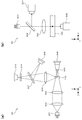
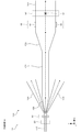
- FIG. 1 is a schematic diagram when the configuration of the particle imaging apparatus according to the first embodiment is viewed in the negative Z-axis direction.
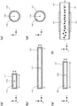
- 2 (a) to 2 (e) are cross-sectional views of the first flow path part, the second flow path part, the third flow path part, the fourth flow path part, and the fifth flow path part according to Embodiment 1, respectively.
- FIG. 2 is a schematic diagram illustrating the formation of ultrasonic standing waves according to the first embodiment.
- FIG. 3A is a schematic diagram when the particle detection unit according to the first embodiment is viewed in the negative X-axis direction
- FIG. 3B is a diagram illustrating the particle imaging unit according to the first embodiment in the Y-axis positive direction. It is a schematic diagram at the time of seeing.
- FIG. 1 is a schematic diagram when the configuration of the particle imaging apparatus according to the first embodiment is viewed in the negative Z-axis direction.
- 2 (a) to 2 (e) are cross-sectional views of the first flow path part, the second flow
- FIGS. 5A to 5C are flowcharts showing processing performed by the particle imaging apparatus according to the first embodiment.
- 6A is a flowchart illustrating display processing performed by the particle imaging apparatus according to the first embodiment
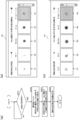
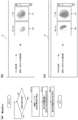
- FIGS. 6B and 6C illustrate screens displayed on the output unit according to the first embodiment.
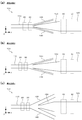
- FIG. FIGS. 7A to 7C are schematic views of flow paths according to Embodiments 2 to 4, respectively.
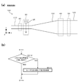
- FIGS. 8A and 8B are schematic views of flow paths according to Embodiments 5 and 6, respectively, and
- FIG. 8C is a flowchart illustrating processing performed by the particle imaging apparatus according to Embodiment 6. is there.
- FIG. 9 is a schematic diagram of a flow channel according to the seventh embodiment.
- FIG. 10A is a schematic diagram showing that a channel is formed by a member attached on the piezoelectric crystal substrate according to the seventh embodiment
- FIG. 10C is a perspective view schematically showing the piezoelectric crystal substrate, members, and comb-shaped electrodes according to the seventh embodiment.
- FIG. 11A is a schematic diagram when the particle detection unit according to the seventh embodiment is viewed in the negative X-axis direction
- FIG. 11B illustrates a modification example of the particle detection unit according to the seventh embodiment. It is a schematic diagram.
- FIG. 12A is a schematic diagram of a flow channel according to the eighth embodiment, and FIG.
- FIG. 12B is a flowchart illustrating processing performed by the particle imaging apparatus according to the eighth embodiment.
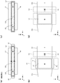
- FIGS. 13A and 13B are schematic views showing a cross section of the second flow path part according to the ninth embodiment, and FIGS. 13C and 13D are partially modified configurations of the ninth embodiment.
- It is a schematic diagram which shows the example of a structure.
- FIG. 14A is a schematic diagram showing a cross section of the second flow path part according to the tenth embodiment, and FIG. 14B shows the vicinity of the second flow path part according to the tenth embodiment in the negative Z-axis direction. It is a schematic diagram when seen.
- FIG. 14C is a schematic diagram showing a configuration example in which the configuration of the embodiment 10 is partially changed.
- FIG. 14D shows the vicinity of the second flow path portion in this configuration example in the negative Z-axis direction.
- FIG. FIGS. 15A and 15B are schematic views showing a cross section of the second flow path part according to the eleventh embodiment
- FIG. 15C is a flowchart showing the control for the particle alignment part in the eleventh embodiment. is there.
- FIGS. 16A and 16B are schematic views showing a cross section of the second flow path part according to the twelfth embodiment
- FIG. 16C is a flowchart showing the control for the particle alignment part in the twelfth embodiment. is there.
- FIG. 17A is a flowchart showing display processing performed by the particle imaging apparatus according to the thirteenth embodiment
- FIG. 17B and 17C show screens displayed on the output unit according to the thirteenth embodiment.
- FIG. FIG. 18 (a) is a diagram showing an example of an image obtained by imaging the fluorescence of the nucleus and signal molecule of the vascular endothelial cell in the activated state according to the thirteenth embodiment, and FIG. It is a figure which shows the example of the image which imaged the fluorescence of the nucleus and signal molecule
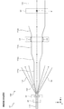
- FIG. 19 is a schematic diagram when the configuration of the particle imaging apparatus according to the fourteenth embodiment is viewed in the negative Z-axis direction.
- FIG. 20 is a schematic diagram when the configuration of the particle imaging apparatus according to the modification of the fourteenth embodiment is viewed in the negative Z-axis direction.
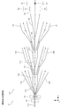
- FIG. 21 is a schematic diagram when the configuration of the particle imaging apparatus according to the fifteenth embodiment is viewed in the negative Z-axis direction.
- FIG. 22 is a simulation result obtained by analyzing the flow velocity of each flow path unit in the particle imaging device according to the fifteenth embodiment.
- FIGS. 23A and 23B are schematic views when the upstream and downstream branch portions of the particle imaging apparatus according to the fifteenth embodiment are viewed in the negative Z-axis direction, respectively.
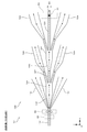
- FIG. 24 is a schematic diagram when the configuration of the particle imaging apparatus according to the modification of the fifteenth embodiment is viewed in the negative Z-axis direction.
- FIG. 24 is a schematic diagram of a configuration of a particle imaging apparatus according to another modification of the fifteenth embodiment when viewed in the negative Z-axis direction.
- the drawings are for explanation only and do not limit the scope of the present invention.
- Embodiments 1 to 12 shown below apply the present invention to an apparatus for imaging blood circulating tumor cells contained in a blood sample.
- CTC Circulating Tumor Cell
- Advanced cancer cells circulate in the flow of blood and lymph and metastasize to distant organs.
- the usefulness of CTCs in blood is useful as a determination of therapeutic effect and a prognostic predictor in patients with metastatic cancer such as breast cancer, prostate cancer, and colon cancer.
- Measuring CTC is effective when it is desired to predict the prognosis, such as judgment of the effect of treatment, progression-free survival rate, overall survival rate, etc.
- the amount of CTC circulating in the blood is extremely small, and it is several to several tens in 10 mL of blood.
- the imaging target of the present invention is not limited to CTC, and may be other cells included in a blood sample.
- the particle imaging device 10 includes a flow channel 100, a particle detection unit 20, a particle sorting unit 30, a particle alignment unit 40, and a particle imaging unit 50.
- FIG. 1 shows XYZ coordinate axes orthogonal to each other.
- the flow path 100 includes a first flow path section 110, a second flow path section 120, a third flow path section 130, a fourth flow path section 140, and a fifth flow path section 150.
- Each flow path part is comprised with the glass and synthetic resin which have translucency.
- a measurement sample 12 containing particles flows through the flow channel 100.
- the measurement sample 12 is prepared based on the blood sample 11 as described later with reference to FIG.
- the negative X-axis side is the upstream side
- the positive X-axis side is the downstream side.
- the first flow path part 110 and the second flow path part 120 are arranged in a straight line.
- the second flow path part 120 is connected to the downstream side of the first flow path part 110, that is, the X-axis positive side of the first flow path part 110 via the fifth flow path part 150.
- the third flow path part 130 and the fourth flow path part 140 are branched from the first flow path part 110 between the first flow path part 110 and the second flow path part 120.
- the downstream side of the second flow path part 120, the downstream side of the third flow path part 130, and the downstream side of the fourth flow path part 140 are open to the atmosphere and connected to a waste liquid storage part (not shown).
- the first flow path part 110 is a space surrounded by a member 111.
- a central axis 112 of the first flow path part 110 extends in the X-axis direction.
- the cross-sectional shape of the first flow path part 110 is a rectangle, and in the cross section of the first flow path part 110, the width in the Y-axis direction is larger than the width in the Z-axis direction.
- the cross-sectional area of the first flow path part 110 is constant.
- the second flow path portion 120 is a space surrounded by a member 121.
- the central axis 122 of the second flow path part 120 extends in the X-axis direction.
- the central axis 122 is located on an extension line of the central axis 112.
- the cross-sectional shape of the second flow path part 120 is a rectangle, and in the cross section of the second flow path part 120, the width in the Y-axis direction is larger than the width in the Z-axis direction.
- the Z-axis direction width of the cross section of the second flow path part 120 is the same as the Z-axis direction width of the cross section of the first flow path part 110.
- the Y-axis direction width of the cross section of the second flow path part 120 is larger than the Y-axis direction width of the cross section of the first flow path part 110.
- the cross-sectional area of the second flow path part 120 is constant.
- the cross-sectional area of the second flow path part 120 is larger than the cross-sectional area of the first flow path part 110.
- the third flow path part 130 is a space surrounded by a member 131.
- a central axis 132 of the third flow path portion 130 is inclined from the X-axis direction in the XY plane.
- the cross-sectional shape of the third flow path part 130 is circular.
- the cross-sectional area of the third flow path portion 130 gradually increases from the upstream side of the flow path 100 toward the downstream side, that is, along the central axis 132 in the positive direction of the X axis.
- the fourth flow path part 140 is a space surrounded by a member 141.
- the central axis 142 of the fourth flow path part 140 is inclined from the X-axis direction in the XY plane.
- the cross-sectional shape of the fourth flow path part 140 is circular.
- the cross-sectional area of the fourth flow path part 140 gradually increases from the upstream side of the flow path 100 toward the downstream side, that is, along the central axis 142 in the positive direction of the X axis.
- the third flow path part 130 and the fourth flow path part 140 are symmetric with respect to the central axis 112 of the first flow path part 110.
- the fifth flow path 150 is a space surrounded by a member 151.
- a central axis 152 of the fifth flow path part 150 extends in the X-axis direction.
- the central axis 152 is located on an extension line of the central axis 122.
- the cross-sectional shape of the fifth flow path part 150 is a rectangle.
- the Z-axis direction width of the cross section of the fifth flow path portion 150 is the same as the Z-axis direction width of the cross section of the first flow path portion 110.
- the cross-sectional area of the fifth flow path part 150 gradually increases along the central axis 152 in the positive direction of the X axis.
- the measurement sample 12 is flowed from the upstream side of the first flow path unit 110 in a state of being wrapped in the sheath liquid.
- the particles contained in the measurement sample 12 flow through the first flow path part 110 along the central axis 112 in a state of being aligned in a line.
- the particle detection unit 20 irradiates the irradiation position 21 of the first flow path unit 110 with light and receives light generated from the particle at the irradiation position 21 to detect the particle.
- the particle detector 20 includes a light source 201, a collimator lens 202, a condenser lens 203, a beam stopper 204, a photodetector 205, a condenser lens 206, and a dichroic mirror. 207, a photodetector 208, a spectral filter 209, and a photodetector 210.
- the light emitted from the light source 201 is a laser beam in the red wavelength band.
- the collimator lens 202 converts the light emitted from the light source 201 into parallel light.
- the condensing lens 203 condenses the light converted into parallel light.
- the condensed light is irradiated to the particles positioned at the irradiation position 21 shown in FIG. Thereby, forward scattered light, side scattered light, and fluorescence are generated.
- the forward scattered light reflects information on the size of the particles
- the side scattered light reflects internal information of the particles
- the fluorescence reflects the degree of staining of the particles.
- the light transmitted through the first flow path part 110 without being irradiated to the particles is blocked by the beam stopper 204.
- the light detector 205 receives forward scattered light.
- the photodetector 205 is a photodiode, and outputs an electrical signal corresponding to the received forward scattered light, that is, a forward scattered light signal.
- the condensing lens 206 condenses side scattered light and fluorescence.
- the dichroic mirror 207 reflects side scattered light and transmits fluorescence.
- the photodetector 208 receives side scattered light.
- the photodetector 208 is a photodiode and outputs an electrical signal corresponding to the received side scattered light, that is, a side scattered light signal.
- the spectral filter 209 transmits fluorescence.
- the photodetector 210 receives fluorescence.
- the photodetector 210 is an avalanche photodiode and outputs an electrical signal corresponding to the received fluorescence, that is, a fluorescence signal.
- the photodetectors 205, 208, and 210 correspond to the light receiving unit described in the claims.
- the photodetector 205 that receives forward scattered light corresponds to the first detector described in the claims, and the photodetector 210 that receives fluorescence is the second detector described in the claims. It corresponds to.
- the particle sorting unit 30 includes bubble generators 31 and 32. Bubble generators 31 and 32 generate bubbles by heat.
- the particle sorting unit 30 selectively adjusts the traveling direction of the particles flowing through the first channel unit 110 from the second channel unit 120 and the third channel unit 130 for each particle.
- the particle sorting unit 30 when the particle sorting unit 30 is driven, bubbles generated by the bubble generators 31 and 32 are applied to the particles flowing through the first flow path unit 110. As a result, the traveling direction of the particles at the position of the particle sorting unit 30 changes from the X-axis positive direction toward the third flow path unit 130, and the particles flow to the third flow path unit 130. When the particle sorting unit 30 is not driven, the traveling direction of the particles at the position of the particle sorting unit 30 does not change from the positive direction of the X axis, and the particles are flowed to the fifth channel unit 150 and the second channel unit 120. Washed away.
- Whether the particles that have reached the position of the particle sorting unit 30 are allowed to flow to the third channel unit 130 or the second channel unit 120 is determined by the control unit 13 for each particle based on the detection result by the particle detection unit 20. decide. Particles that are determined to require imaging are flowed to the second flow path unit 120, and particles that are determined not to be imaged are flowed to the third flow path unit 130. Such determination will be described later with reference to FIG.
- the particle sorting unit 30 causes the particles determined to be imaged by the particle imaging unit 50 to advance straight without applying an external force, and the second flow through the fifth flow path unit 150. Guide to the road 120.
- the particle sorting unit 30 applies an external force to the particles determined not to be imaged by the particle imaging unit 50 to change the traveling direction and guides the particles to the third flow path unit 130. Accordingly, only particles that are highly likely to be imaged can be stably guided to the second flow path unit 120.
- the particle sorting unit 30 may include a piezoelectric actuator having a piezoelectric body and an electrode, or an ultrasonic wave generating unit having a piezoelectric crystal substrate and a comb-shaped electrode, instead of the bubble generators 31 and 32.
- the node of the ultrasonic standing wave generated by the piezo actuator or the ultrasonic wave generator is positioned on the Y axis positive side or the Y axis negative side of the central axis 112.
- the third flow path part 130 and the fourth flow path part 140 are branched from the first flow path part 110 between the first flow path part 110 and the second flow path part 120.
- the sheath liquid flowing through the first flow path part 110 is divided into the third flow path part 130, the fourth flow path part 140, and the fifth flow path part 150.
- the sheath liquid that has flowed to the third flow path part 130 and the sheath liquid that has flowed to the fourth flow path part 140 are accommodated in a waste liquid storage part (not shown).
- the particles that have flowed into the fifth flow path portion 150 travel along the central axis 152 through the fifth flow path portion 150 in the positive direction of the X axis and flow into the second flow path portion 120.
- the third flow path portion 130 and the fourth flow path portion 140 are configured to be symmetric with respect to the central axis 112 of the first flow path portion 110.
- the sheath liquid flowing through the first flow path portion 110 flows through the third flow path portion 130 and the fourth flow path portion 140 substantially evenly.
- the velocity of the particles flowing to the second flow path part 120 via the fifth flow path part 150 is stabilized, and the particle imaging unit 50 can capture a more accurate image.
- the particle alignment unit 40 includes piezoelectric actuators 41 and 42 disposed on the side surface of the second flow path unit 120.
- the piezo actuators 41 and 42 have a piezoelectric body and electrodes.
- the piezoelectric body may be a film or a bulk.
- Examples of the piezoelectric material include Pb (Zr, Ti) O 3 , BaTiO 3 , (K, Na) NbO 3 , Pb (Mn, Nb) O 3 —PbTiO 3 , ZnO, and SiO 2. It is not limited to.
- a longitudinal mode may be used, or a sliding mode may be used.
- the particle alignment unit 40 aligns the particle position with the central axis 122 and aligns the particles flowing through the second flow path unit 120 in the flow direction.
- the particle alignment unit 40 is a particle that flows through the second flow channel unit 120 from both sides of the second flow channel unit 120 in a direction perpendicular to the imaging direction by the particle imaging unit 50 and the flow direction of the particles, that is, in the Y-axis direction. Apply ultrasonic waves to.
- the material of the member 121 constituting the second flow path portion 120 It is desirable to use a material having high rigidity and low sound wave attenuation as the material of the member 121 constituting the second flow path portion 120. Quartz and silicon can be cited as materials having high rigidity. By using a material with small attenuation of sound waves as the material of the member 121, an acoustic force can be effectively applied to the particles in the measurement sample.
- a piezo actuator is used as the particle sorting unit 30, the material of the member 111 constituting the first flow path unit 110 is also highly rigid and the sound wave attenuation is the same as the member 121 constituting the second flow path unit 120. It is desirable to use a material having a small value.
- the ultrasonic wave generation part which has a piezoelectric crystal substrate and a comb-shaped electrode as the particle
- an acoustic force can be effectively applied to the particles in the measurement sample.
- the third flow path part 130, the fourth flow path part 140, and the fifth flow path part 150 may be made of the same material as the second flow path part 120.
- the particle alignment unit 40 may be an ultrasonic wave generation unit having a piezoelectric crystal substrate and a comb-shaped electrode instead of the piezoelectric actuators 41 and 42 as long as an ultrasonic standing wave can be formed.
- the configuration of the ultrasonic generator will be described with reference to the seventh embodiment.
- the particle imaging unit 50 irradiates the imaging region 51 of the second flow path unit 120 with light and receives light from the imaging region 51 to image particles flowing in the imaging region 51.
- the imaging region 51 is an imaging range by the particle imaging unit 50.
- the size of the imaging region 51 is set so as to include particles flowing along the central axis 122.
- the particle imaging unit 50 includes a light source 501, a dichroic mirror 502, an objective lens 503, and cameras 504 and 505.
- the light emitted from the light source 501 is laser light having a wavelength of about 488 nm.
- the dichroic mirror 502 transmits light emitted from the light source 501 and reflects fluorescence.
- the objective lens 503 collects the light transmitted through the dichroic mirror 502. The condensed light is applied to the imaging region 51 shown in FIG. Thereby, when light is irradiated to the stained particles, fluorescence is generated from the particles.
- the objective lens 503 collects fluorescence generated from the particles.
- the dichroic mirror 502 reflects fluorescence.
- Cameras 504 and 505 are TDI (Time Delay Integration) cameras.
- the camera 504 receives fluorescence of different wavelengths and outputs image information for each fluorescence.
- the dichroic mirror 502 is provided with a plurality of reflecting surfaces according to the fluorescence wavelength, and the tilt angle of each reflecting surface of the dichroic mirror 502 is adjusted so that the imaging region in the camera 504 is separated for each fluorescence wavelength. It may be.
- the captured image of the camera 504 is divided into a plurality of regions corresponding to each fluorescence.
- the image information of each area becomes image information for each fluorescence.
- the camera 505 receives the light transmitted through the particles and outputs bright field image information.
- the direction in which the cameras 504 and 505 image the particles is the Z-axis direction.
- the width in the direction perpendicular to the imaging direction and the particle flow direction that is, the width in the Y-axis direction is larger than the width in the imaging direction, that is, the width in the Z-axis direction. Therefore, since the particles hardly overlap in the Z-axis direction, the particle imaging unit 50 can acquire an image for each particle.
- the flow rate of the sheath liquid and the measurement sample 12 in the second flow path part 120 is decreased from the flow rate of the sheath liquid and the measurement sample 12 in the first flow path part 110 by the third flow path part 130 and the fourth flow path part 140. ing. Specifically, the flow rate of the sheath liquid and the measurement sample 12 in the first flow path part 110 is 100 ⁇ L / s, whereas the flow rate of the sheath liquid and the measurement sample 12 in the second flow path part 120 is 30 ⁇ L / s. It has become. For this reason, the flow rate of the sheath liquid and the measurement sample 12 in the second flow path part 120 is 1/3 or less of the flow rate of the sheath liquid and the measurement sample 12 in the first flow path part 110.
- the flow rates of the sheath liquid and the measurement sample 12 in the third flow path part 130 and the fourth flow path part 140 are 35 ⁇ L / s, respectively. Thereby, the speed of the particles flowing through the second flow path part 120 is lower than the speed of the particles flowing through the first flow path part 110.
- the cross-sectional area of the second flow path part 120 is larger than the cross-sectional area of the first flow path part 110 as described above.
- the speed of the particles flowing through the second flow path part 120 is further reduced than the speed of the particles flowing through the first flow path part 110.
- the velocity of the particles flowing through the first flow passage portion 110 is 1.0 m / s
- the velocity of the particles flowing through the second flow passage portion 120 is 0.1 m / s.
- the speed of the particles flowing through the second flow path section 120 is 1/10 or less of the speed of the particles flowing through the first flow path section 110.
- the speed of the particles flowing through the first flow path section 110 is increased in order to extract the particles to be imaged from many particles, the speed of the particles flowing through the second flow path section 120 is greatly reduced. Therefore, a precise particle image can be captured by the particle imaging unit 50. That is, the particles to be imaged can be imaged with high quality while maintaining the processing speed of the particle imaging device 10.
- the fifth flow path part 150 connects the first flow path part 110 and the second flow path part 120, and the cross-sectional area of the fifth flow path part 150 gradually increases as it goes downstream. Thereby, the speed of the particles can be gradually decreased from the first flow path part 110 to the second flow path part 120. Accordingly, since the velocity of the particles flowing through the second flow path unit 120 is stabilized, a precise particle image can be captured by the particle imaging unit 50.
- the cross-sectional area of the third flow path part 130 and the fourth flow path part 140 gradually increases from the upstream side toward the downstream side. As a result, the measurement sample 12 flowing from the first flow path part 110 toward the third flow path part 130 or the fourth flow path part 140 is less likely to flow into the fifth flow path part 150. Accordingly, since the velocity of the particles flowing through the second flow path unit 120 is stabilized, a precise particle image can be captured by the particle imaging unit 50.
- the particles imaged by the particle imaging unit 50 flow through the second flow path unit 120 and are stored in a waste liquid storage unit (not shown).
- a waste liquid storage unit not shown
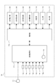
- the particle imaging device 10 includes a control unit 13, a sample preparation unit 14, A storage unit 15, an input unit 16, and an output unit 17 are provided.
- the control unit 13 includes an arithmetic processing circuit such as a CPU, and controls each unit of the particle imaging apparatus 10 according to a program stored in the storage unit 15.
- the storage unit 15 includes a storage medium such as a ROM, a RAM, and a hard disk.
- the sample preparation unit 14 receives a blood sample 11 which is peripheral blood collected from a patient.
- the sample preparation unit 14 is connected to a container for storing the reagents 14a to 14g.
- the reagent 14a includes a hemolytic agent that hemolyzes red blood cells.
- the reagent 14b contains a CD45 labeled antibody for detecting leukocytes.
- Reagent 14c contains a Ch17 probe that binds to chromosome 17.
- Reagent 14d includes a Her2 probe that binds to the Her2 gene.
- Reagent 14e contains an antibody that binds to the Ch17 probe labeled with the dye name Alexa488.
- the reagent 14f includes an antibody that binds to the Her2 probe labeled with the dye name PE.
- the reagent 14g contains a dye 7AAD that stains the nucleus. In these dyes, fluorescence having different wavelengths is excited by light having a wavelength of about 488 nm emitted from the light source 501.
- the dye of the reagent 14e may be FITC instead of Alexa488.
- the dye of the reagent 14f may be PE-Cy7 instead of PE.
- the sample preparation unit 14 prepares the measurement sample 12 by mixing the blood sample 11 and the reagents 14a to 14g. The measurement sample 12 is passed through the flow channel 100 shown in FIG.
- the light source 501 is changed to a light source that emits a plurality of lights according to the excitation wavelengths of the dyes.
- a light source a multi-emitting laser in which a plurality of light emitting elements are mounted on a substrate can be used.
- the light source 501 may be configured to combine laser beams emitted from a plurality of semiconductor lasers with a dichroic mirror.
- Alexa647 and HOECHST are mentioned as a pigment having an excitation wavelength different from that of Alexa488. Alexa647 can be used to label the Her2 gene and HOECHST can be used to label the nucleus.
- the control unit 13 acquires signal waveforms corresponding to forward scattered light, side scattered light, and fluorescence based on signals output from the photodetectors 205, 208, and 210 of the particle detection unit 20.
- the control unit 13 acquires the peak value of the signal waveform corresponding to each light for each particle.
- the peak value of the signal waveform of the forward scattered light signal, the peak value of the signal waveform of the side scattered light signal, and the peak value of the fluorescence signal waveform are respectively the intensity of the forward scattered light signal, the intensity of the side scattered light signal, and the fluorescence. Corresponds to signal strength.
- the control unit 13 stores the peak value of the signal waveform corresponding to each light acquired for each particle in the storage unit 15.
- the control unit 13 drives the particle sorting unit 30 to select the traveling direction of the particles.
- the control unit 13 drives the particle alignment unit 40 to align the position of the particles flowing through the second flow path unit 120 with the central axis 122.
- the control unit 13 generates a particle image based on the output signals of the cameras 504 and 505 of the particle imaging unit 50, and stores the generated image in the storage unit 15.
- the control unit 13 analyzes the captured image and displays the particle image on the output unit 17.
- the control unit 13 receives an instruction from the operator via the input unit 16 and causes the output unit 17 to display a captured image of the particle.
- the input unit 16 is a mouse or a keyboard, and the output unit 17 is a display such as a liquid crystal panel.
- the control unit 13 drives the particle imaging device 10 to suck the blood sample 11 and supply it to the sample preparation unit 14, and the processes shown in FIGS. 5 (a) to 5 (c). And start each process in parallel.
- step S101 the sample preparation unit 14 mixes the blood sample 11 and the reagents 14a to 14g to prepare the measurement sample 12.
- the red blood cells in the blood sample 11 are hemolyzed by the action of the reagent 14a, and the labeled antibody CD45 in the reagent 14b and the surface antigen CD45 of the white blood cells in the blood sample 11 are combined.
- the blood sample 11 and the reagents 14c to 14g are mixed.
- step S ⁇ b> 102 the control unit 13 drives the light source 201 of the particle detection unit 20 to irradiate the irradiation position 21 of the first channel unit 110 with light at a predetermined speed from the upstream side of the first channel unit 110.
- the measurement sample 12 is flowed.
- step S103 the control unit 13 detects the forward scattered light signal, the side scattered light signal, and the fluorescence signal by the photodetectors 205, 208, and 210 of the particle detection unit 20, respectively, and the first flow path unit. Detection of particles in the measurement sample 12 flowing through 110 is started.
- the fluorescence signal obtained from the CD45 labeled antibody is acquired by the photodetector 210.
- the control unit 13 acquires the intensity of the forward scattered light signal, the intensity of the side scattered light signal, and the intensity of the fluorescent signal for each particle.
- step S104 the control unit 13 determines whether or not the particles at the irradiation position 21 are likely to be CTC. Specifically, the control unit 13 may determine that the particle at the irradiation position 21 is CTC when the intensity of the fluorescent signal is equal to or lower than a predetermined threshold and the intensity of the forward scattered light signal is equal to or higher than the predetermined threshold. Judgment is high. That is, particles whose fluorescence signal is larger than the predetermined threshold and particles whose forward scattered light signal intensity is smaller than the predetermined threshold are excluded from the imaging target. When the particles are CTC, since the particles do not bind to the CD45 labeled antibody, the intensity of the fluorescence signal becomes a predetermined value or less.
- step S104 when the particle is a particle other than a white blood cell and the size of the particle is large, the control unit 13 determines that the possibility that the particle is CTC is high.
- the reagent 14a for lysing red blood cells may not be used. Even in this case, the red blood cells are small in size and the intensity of the forward scattered light signal is less than a predetermined threshold value, so the red blood cells in the measurement sample 12 are excluded from the imaging target.
- step S105 the control part 13 will memorize
- FIG. in step S ⁇ b> 106 the control unit 13 determines whether all the particles have passed through the irradiation position 21 after flowing the measurement sample 12 through the first flow path unit 110. The control unit 13 repeats the processes of steps S104 and S105 for each particle positioned at the irradiation position 21 until all the particles pass through the irradiation position 21. When all the particles pass through the irradiation position 21, the process is finished.
- step S111 the control unit 13 turns on the operation of the particle sorting unit 30.
- step S112 the control unit 13 determines whether or not the particles positioned in the particle sorting unit 30 are likely to be CTCs. Specifically, when a predetermined time has elapsed from the timing stored in step S105, the control unit 13 determines that the particles that are determined to be highly likely to be CTC in step S104 in FIG. It is assumed that the particle sorting unit 30 is positioned.
- step S113 the control unit 13 turns off the operation of the particle sorting unit 30.
- particles that are determined to be highly likely to be CTC are flowed to the second flow path portion 120 via the fifth flow path portion 150.
- the control part 13 will continue the operation
- particles that are determined to be less likely to be CTC are caused to flow through the third flow path unit 130.
- the control unit 13 adjusts the traveling direction of the particles flowing through the first flow path unit 110 by driving the particle sorting unit 30 based on the intensity of the fluorescence signal.
- step S ⁇ b> 114 the control unit 13 determines whether all the particles have passed through the particle sorting unit 30 after the measurement sample 12 has flowed through the first flow path unit 110.
- the control unit 13 repeats the processes of steps S112 and S113 for each particle positioned in the particle sorting unit 30 until all the particles pass through the particle sorting unit 30. When all the particles have passed through the particle sorting unit 30, the process ends.
- step S121 the control unit 13 drives the light source 501 of the particle imaging unit 50 to irradiate the imaging region 51 of the second flow path unit 120 with light.
- step S122 the control unit 13 drives the cameras 504 and 505 of the particle imaging unit 50 to start imaging particles. In this manner, the control unit 13 drives the particle imaging unit 50 to image particles that are highly likely to be CTC.
- the control unit 13 monitors the captured images of the cameras 504 and 505, extracts a captured image including particles from the series of captured images as a particle image, and stores the extracted image in the storage unit 15.
- step S ⁇ b> 123 the control unit 13 determines whether all particles have passed through the particle imaging unit 50 after the measurement sample 12 has been passed through the first flow path unit 110. The control unit 13 continues to image particles passing through the imaging region 51 until all particles pass through the particle imaging unit 50. When all the particles pass through the imaging region 51, the process ends.
- step S201 the control unit 13 determines whether a result display instruction is input by the operator. If YES is determined in step S201, in step S202, the control unit 13 performs image analysis on the images of all particles captured in the process illustrated in FIG. Cells containing dots and bright spots based on the Her2 gene are extracted. Further, in step S202, the control unit 13 analyzes the extracted cell image, determines whether each cell has the Her2 gene amplification, and extracts the cell having the Her2 gene amplification as a CTC. Here, the control unit 13 extracts cells having three or more bright spots based on the Her2 gene in the nucleus as cells having the Her2 gene amplification, that is, CTC.
- step S203 the control unit 13 displays the number of cells including bright spots and the number of cells (CTC) with Her2 gene amplification on the output unit 17 based on the extraction result of step S202.
- step S ⁇ b> 204 the control unit 13 displays the cell image including the bright spot extracted in step S ⁇ b> 202 on the output unit 17.
- the screen 60 is displayed on the output unit 17 in steps S203 and S204.
- the screen 60 displays the number of sputum cells including a bright spot, the number of cells (CTC) with Her2 gene amplification, and an image of a cell including a bright spot.
- the operator can know whether Her2 gene amplification has occurred or not by referring to the number of cells, so that doctors and the like can provide useful information for determining the optimal therapeutic agent.
- the five images arranged side by side are images of the same single particle.
- the five images in order from the left are the fluorescence image 61 produced by the dye that labels the chromosome 17 gene, the fluorescence image 62 produced by the dye that labels the Her2 gene, and the dye that stains the nucleus.
- the generated fluorescence image 63, an image 64 obtained by merging the images 61 to 63, and a bright field image 65 are shown. Note that the images 61 to 64 are converted to gray scales after gradation reversal.
- the particle image shown in FIG. 6B is an image of a cell without Her2 gene amplification
- the particle image shown in FIG. 6C is an image of a breast cancer cell with Her2 gene amplification.
- the operator can switch and display the particle images on the screen 60.
- a button or the like that can individually display a display of an image of a cell with Her2 gene amplification and a display of an image of a cell without Her2 gene amplification may be provided on the screen 60.
- the number of bright spots in the image 61 represents the number of chromosome 17 genes (Ch17).
- the number of bright spots in the image 62 represents the number of Her2 genes.
- the bright spots in the image 63 represent nuclei.
- the operator can know whether or not the chromosome 17 gene and the Her2 gene exist in the nucleus by actually referring to the image.
- FIG. 6B when there is no amplification of the Her2 gene, as shown in FIG. 6B, there are two bright spots in the images 61 and 62, and when there is amplification of the Her2 gene, as shown in FIG. 6C.
- the image 61 has two bright spots and the image 62 has more than two bright spots. Thereby, the operator can know whether Her2 gene amplification has occurred by actually referring to the image.
- the third flow path portion 130 and the fourth flow path portion 140 are configured so that the cross-sectional area increases as they proceed downstream, but the cross-sectional area is constant as shown in FIG. May be.
- the second embodiment as compared to the first embodiment, as shown in FIG. 7A, only the shape of the third flow path portion 130 and the shape of the fourth flow path portion 140 are different.
- Other configurations and processing of the particle imaging apparatus 10 are the same as those in the first embodiment.
- the flow rate of the measurement sample 12 in the second flow path part 120 is reduced from the flow rate of the measurement sample 12 in the first flow path part 110.
- the speed of the particles flowing through the second flow path portion 120 is lower than the speed of the particles flowing through the first flow path portion 110. Therefore, a precise particle image can be captured by the particle imaging unit 50.
- the downstream end of the first flow path part 110 is divided into three parts, and the third flow path part 130, the fourth flow path part 140, and the fifth flow path part 150 are connected to each other.
- the third flow path part 130 and the fourth flow path part 140 may be branched from the side surface of the first flow path part 110.
- the third embodiment differs from the second embodiment only in the branch position of the third flow path portion 130 and the branch position of the fourth flow path portion 140.
- Other configurations and the processing of the particle imaging apparatus 10 are the same as those in the second embodiment.
- the third embodiment since the cross-sectional area is increased at the downstream end of the first flow path portion 110, the flow velocity once decreases, but at the upstream end of the fifth flow passage portion 150, the flow speed is decreased. Goes up again. As described above, when the flow velocity changes nonlinearly, the velocity of the particles flowing through the second flow path portion 120 becomes unstable. Therefore, when the second and third embodiments are compared, it is desirable that the third flow path portion 130 and the fourth flow path portion 140 branch from the first flow path portion 110 as in the second embodiment.
- the cross-sectional area of the fifth flow path portion 150 may be constant in the vicinity of the upstream end portion.
- the shape of the 5th flow path part 150 is different, and the cross-sectional areas of the 3rd flow path part 130 and the 4th flow path part 140 are large.
- Other configurations and processing of the particle imaging apparatus 10 are the same as those in the third embodiment.
- Embodiment 5 As shown to Fig.8 (a), in Embodiment 4, the 4th flow path part 140 may be abbreviate
- the fifth flow path part 150 and the second flow path part 120 may be inclined.
- the fifth flow path portion 150 and the second flow path portion 120 are inclined.
- step S113 is deleted and steps S301 and S302 are added in the process illustrated in FIG. 5B.
- Other configurations and other processes of the particle imaging apparatus 10 are the same as those in the fifth embodiment.
- step S301 when the control unit 13 determines that the particle positioned in the particle sorting unit 30 is a particle having a high possibility of being a CTC, in step S301, the control unit 13 sends the particle downward.
- the bubble generators 31 and 32 of the particle sorting unit 30 are driven.
- the bubble generator of the particle sorting unit 30 sends the particles upward in step S302. 31 and 32 are driven.
- the flow channel 100 may be provided on a transmissive piezoelectric crystal substrate 101.
- the piezoelectric crystal substrate 101 is made of LiNbO 3 .
- a member 102 made of PDMS is attached on the piezoelectric crystal substrate 101.
- Each channel portion of the channel 100 is formed, for example, as shown in FIG. 10A by affixing a member 102 made of PDMS on the piezoelectric crystal substrate 101.
- the cross-sectional shapes of the first flow path part 110, the second flow path part 120, and the fifth flow path part 150 are the same as those in FIGS. 2A, 2B, and 2E, respectively.
- the cross-sectional shape of the 3rd flow path part 130 and the 4th flow path part 140 is a rectangle.
- the flow path 100 further includes a sixth flow path section 161, a seventh flow path section 162, and an eighth flow path section 163 on the upstream side of the first flow path section 110.
- the seventh flow path part 162 and the eighth flow path part 163 merge with the sixth flow path part 161 from the Y axis positive side and the Y axis negative side of the sixth flow path part 161.
- These channel portions are also formed by attaching the member 102 on the piezoelectric crystal substrate 101, and the cross-sectional shape of these channel portions is also rectangular.
- the measurement sample 12 is flowed from the upstream side of the sixth flow path portion 161.
- the particles contained in the measurement sample 12 flow through the first flow path portion 110 in a state of being wrapped in the sheath liquid flowed from the upstream side of the seventh flow path portion 162 and the eighth flow path portion 163.
- Each part of the particle imaging device 10 excluding the flow channel 100 is the same as that in the first embodiment. Hereinafter, differences from the first embodiment will be described.
- the particle alignment unit 40 includes comb-shaped electrodes 43 and 44 formed on the surface of the piezoelectric crystal substrate 101 by a semiconductor manufacturing technique.
- the particle alignment unit 40 applies ultrasonic waves to the particles flowing through the second flow path unit 120 by flowing current through the comb-shaped electrodes 43 and 44.
- a current is passed through the comb electrodes 43 and 44, the piezoelectric crystal substrate 101 in the vicinity of the comb electrodes 43 and 44 vibrates, and an ultrasonic standing wave is formed. That is, the comb-shaped electrodes 43 and 44 and the piezoelectric crystal substrate 101 in the vicinity of the comb-shaped electrodes 43 and 44 collectively function as an ultrasonic wave generation unit.
- the node of the ultrasonic standing wave is positioned on the central axis 122 shown in FIG. As a result, the particles flowing through the second flow path portion 120 flow along the central axis 122, so that the particles pass through the imaging region 51 on the downstream side. Therefore, the particle imaging unit 50 on the downstream side can reliably image particles.
- the particle sorting unit 30 includes comb electrodes 33 and 34 formed on the surface of the piezoelectric crystal substrate 101 by a semiconductor manufacturing technique instead of the bubble generators 31 and 32. Also in this case, the comb-shaped electrodes 33 and 34 and the piezoelectric crystal substrate 101 in the vicinity of the comb-shaped electrodes 33 and 34 collectively function as an ultrasonic wave generation unit.
- the piezoelectric crystal substrate 101 in the vicinity of the comb electrodes 33 and 34 vibrates to form an ultrasonic standing wave.
- the node of the ultrasonic standing wave is positioned on the Y axis positive side of the central axis 112. Thereby, the particles are sent to the third flow path part 130.
- the particle alignment unit 70 includes comb-shaped electrodes 71 and 72. As a result, the particles flowing through the first flow path portion 110 flow along the central axis 112 of the first flow path portion 110.
- the particle detector 20 includes a light source 211, a dichroic mirror 212, condenser lenses 213 and 215, and photodetectors 214, 216, and 217.
- the light source 211 is the same as the light source 201 in FIG. 2A, and the photodetectors 214, 216, and 217 are the same as the photodetectors 205, 208, and 210 in FIG. 2A, respectively.
- the light emitted from the light source 211 passes through the dichroic mirror 212 and is irradiated onto the particles. Thereby, forward scattered light, side scattered light, and fluorescence are generated.
- the forward scattered light and the side scattered light are collected by the condenser lenses 213 and 215, respectively, and the fluorescence is reflected by the dichroic mirror 212.
- the photodetectors 214, 216, and 217 receive forward scattered light, side scattered light, and fluorescence, respectively.
- the particle detection unit 20 has a configuration illustrated in FIG. 11B instead of the configuration illustrated in FIG.
- the light emitted from the light source 211 is applied to the particles from an oblique direction.
- the photodetector 216 receives the side scattered light transmitted through the dichroic mirror 212, and the photodetector 217 receives the fluorescence reflected by the dichroic mirror 212. In this case, forward scattered light cannot be received. Therefore, the configuration shown in FIG. 11B can be used only when the forward scattered light intensity is not used in the subsequent processing.
- the particle sorting unit 30 of the eighth embodiment includes a laser light source 35 that emits high-power laser light instead of the bubble generators 31 and 32, as compared with the first embodiment. ing. Further, the third flow path part 130 and the fourth flow path part 140 are omitted, and the width of the second flow path part 120 in the Y-axis direction is increased. Also, as shown in FIG. 12B, in the eighth embodiment, step S113 is deleted and step S311 is added in the process shown in FIG. 5B. Other configurations and other processes of the particle imaging apparatus 10 are the same as those in the first embodiment.
- step S ⁇ b> 311 the control unit 13 sets the first flow path unit 110. Laser particles are irradiated to destroy the particles positioned on the particle sorting unit 30. That is, the control unit 13 destroys particles other than the particles to be imaged.
- the second flow path unit 120 only the particles to be imaged are sent to the second flow path unit 120. Further, since the cross-sectional area of the second flow path part 120 is larger than the cross-sectional area of the first flow path part 110, the velocity of the particles flowing through the second flow path part 120 is the speed of the particles flowing through the first flow path part 110. It is lower than the speed. Therefore, it is possible to image the particles to be imaged with high quality while maintaining the processing speed of the particle imaging device 10.
- the thickness of the member 121 that forms the second flow path portion 120 is different from that in the first embodiment.
- the member 121 includes rectangular recesses 123 and 124 on the side surface where the piezoelectric actuators 41 and 42 are disposed. Due to the recesses 123 and 124, the thickness of the side surface portion of the member 121 where the piezo actuators 41 and 42 are disposed is smaller than the other portions.
- the member 121 with the recesses 123 and 124 to reduce the thickness of the member 121, it is possible to suppress attenuation when ultrasonic waves generated from the piezo actuators 41 and 42 propagate through the member 121. Therefore, a highly accurate ultrasonic standing wave can be generated in the second flow path part 120. Thereby, the particles can be aligned more accurately near the central axis 122.
- a reflector 45 that reflects sound may be installed in the recess 124 instead of the piezo actuator 42.
- an ultrasonic standing wave is generated in the second flow path portion 120 by the ultrasonic wave applied to the second flow path portion 120 by the piezoelectric actuator 42 and the reflected wave reflected by the reflection plate 45.
- Arise. By adjusting the width of the second flow path part 120 in the Y-axis direction and the amplitude and frequency of the ultrasonic wave applied to the second flow path part 120 by the piezo actuator 42, the ultrasonic wave is present in the second flow path part 120. Can cause waves.
- the piezoelectric actuator 42 can be omitted, so that the configuration can be simplified and the cost can be reduced.
- a reflecting plate 45 that reflects sound may be installed instead of the piezo actuator 42.
- One of the two piezoelectric actuators 41 and 42 sandwiching the second flow path portion 120 in the Y-axis direction may be replaced with the reflection plate 45.
- a plurality of piezoelectric actuators 41 may be arranged in the X-axis direction.
- a plurality of pairs of the piezoelectric actuator 41 and the reflective plate 45 may be disposed in the X-axis direction.
- a plurality of sets of the piezoelectric actuators 41 and 42 may be arranged in the X-axis direction.
- the piezo actuators 41 and 42 may be installed by being pressed against the side surface of the member 121 constituting the second flow path portion 120 via the acoustic coupling agent 46.
- the acoustic coupling agent 46 preferably has the same acoustic impedance as that of the member 121 constituting the second flow path portion 120.
- the acoustic coupling properties of the piezo actuators 41 and 42 with respect to the second flow path portion 120 are enhanced, so that the ultrasonic waves generated from the piezo actuators 41 and 42 easily propagate to the second flow path portion 120. Become. Therefore, a highly accurate ultrasonic standing wave can be generated in the second flow path part 120. Thereby, the particles can be aligned more accurately near the central axis 122.
- an acoustic coupling agent 46 may be interposed between the piezoelectric actuators 41 and 42 and the side surface of the member 121.
- the acoustic coupling agent 46 may be interposed between the piezo actuator 41 and the side surface of the member 121 and also between the reflection plate 45 and the side surface of the member 121.
- the piezo actuators 41 and 42 and the reflection plate 45 are in close contact with the side surface of the member 121 constituting the second flow path unit 120 in order to improve the ultrasonic wave propagation.
- the members 121 constituting the second flow path part 120 do not necessarily have to have the same thickness at the part where the piezoelectric actuators 41 and 42 are respectively arranged.
- the thicknesses of the portions where the piezoelectric actuators 41 and 42 are respectively arranged are made different from each other, so that the speed at which the sound wave output from the piezoelectric actuators 41 and 42 propagates through the member 121 is made different.
- the position of the node of the ultrasonic standing wave generated in the second flow path part 120 can be changed from the central axis 122 to the Y-axis direction.
- the alignment position of the particles can be controlled.
- the acoustic coupling agent 46 is used as in the configuration of FIG. 13D, the thickness and acoustic impedance of the acoustic coupling agent 46 may be adjusted for the same purpose, or one acoustic coupling agent 46 is omitted. May be.
- piezo actuators 47 and 48 are disposed together with the piezo actuators 41 and 42.
- the piezo actuators 47 and 48 are respectively installed on the side surfaces of the member 121 constituting the second flow path portion 120 in the Z-axis positive / negative direction.
- the piezo actuators 47 and 48 apply ultrasonic waves to the second flow path unit 120 to generate ultrasonic standing waves in the Z-axis direction in the second flow path unit 120. Due to this ultrasonic standing wave, the particles flowing through the second flow path section 120 are aligned so as to approach the central axis 122 even in the Z-axis direction.
- the two piezoelectric actuators 41 and 42 arranged in the Y-axis direction apply acoustic force in the Y-axis direction to the particles to align the particles near the central axis.
- the two piezo actuators 47 and 48 arranged in the Z-axis direction apply acoustic force in the Z-axis direction to the particles to align the particles near the central axis.
- the piezo actuators 47 and 48 are arranged in the Z-axis direction to align the particles, the particles are collected near the central axis 122 in both the Y-axis direction and the Z-axis direction.
- the particles gather at substantially the same position in the Z-axis direction and are easily positioned at the focus position of the particle imaging unit 50. Therefore, the image quality of the captured image of particles can be improved.
- a plurality of sets of piezoelectric actuators 47 and 48 may be arranged in the X-axis direction.
- An acoustic coupling agent may be interposed between the piezo actuators 47 and 48.
- One of the piezoelectric actuators 47 and 48 may be replaced with a reflector.
- the piezoelectric actuators 47 and 48 are omitted, and the ultrasonic standing wave in the Z-axis direction and the ultrasonic standing wave in the Z-axis direction are generated by using only the piezoelectric actuators 41 and 42. It can also be generated in the flow path part 120.
- a signal component for generating an ultrasonic standing wave in the Y-axis direction and a signal component for generating an ultrasonic standing wave in the Z-axis direction are superimposed on the piezoelectric actuators 41 and 42. An input signal is applied.
- a sine wave signal composed of only a single signal component is applied to the piezo actuators 41 and 42, and the ultrasonic standing wave in the Y-axis direction and the ultrasonic standing wave in the Z-axis direction are applied to the second flow. It can also be generated in the road portion 120.
- the characteristics of the signals applied to the piezo actuators 41 and 42 are It is determined.
- the piezo actuators 47 and 48 arranged in the Z-axis direction.
- the piezoelectric actuators 41 and 42 arranged in the Y-axis direction can be omitted.
- the piezo actuators 41 and 42 may be arranged in the Y-axis direction together with the piezo actuators 47 and 48.
- the amplitude of the ultrasonic standing wave 200 generated in the second flow path portion 120 can be changed.
- the amplitude of the ultrasonic standing wave 200 can be changed by adjusting the amplitude of the input signal applied to the piezoelectric actuators 41 and 42.
- the amplitude of the input signal applied to the piezo actuators 41 and 42 is increased, the amplitude of the ultrasonic standing wave 200 is increased, and when the amplitude of the input signal applied to the piezo actuators 41 and 42 is decreased, the ultrasonic standing wave is increased.
- the amplitude of the wave 200 is reduced.
- FIG. 15A shows a case where the amplitude of the ultrasonic standing wave 200 is small
- FIG. 15B shows a case where the amplitude of the ultrasonic standing wave 200 is large.
- the imaging magnification of the particle imaging unit 50 is increased to image one particle with high definition
- the imaging region 51 becomes smaller as the imaging magnification increases as shown in FIG.
- the amplitude of the ultrasonic standing wave 200 is increased so that the particles are aligned with the central axis with higher accuracy. As a result, the particles reliably pass through the imaging region 51, and imaging leakage can be suppressed.
- the imaging area 51 is wide, so that it is not necessary to collect particles around the central axis 122 with high accuracy.
- the amplitude of the ultrasonic standing wave 200 may be reduced to align the particles near the central axis.
- the speed of the measurement sample flowing through the second flow path unit 120 can be changed.
- the speed of the measurement sample flowing through the second flow path portion 120 decreases. Therefore, in the case of FIG. 15B, the speed of the measurement sample can be made slower than in the case of FIG. Therefore, in the case of FIG. 15B, particles can be imaged with higher accuracy.
- the control unit 13 executes, for example, the process shown in FIG.
- the control unit 13 executes the processes of steps S401 and S402 as a pre-process of control for aligning the particles.
- step S ⁇ b> 401 the control unit 13 applies a pulse wave input signal to the piezoelectric actuators 41 and 42. Due to the acoustic force generated by the pulse wave, bubbles or the like attached to the inner wall of the second flow path part 120 when the measurement sample and the sheath liquid are introduced are peeled off from the inner wall of the second flow path part 120 and flow downstream.
- the control unit 13 continues to apply pulse wave input signals to the piezoelectric actuators 41 and 42 until it is determined in step S402 that the predetermined time has elapsed. By removing bubbles and the like in this way, an ultrasonic standing wave can be stably generated in the second flow path unit 120 in the process of Step S403.
- the control unit 13 determines in step S403 whether or not the alignment mode set in the particle imaging device 10 is the first alignment mode.
- the first alignment mode and the second alignment mode can be selectively set as the alignment mode.
- the first alignment mode is a mode for aligning particles near the central axis with normal accuracy
- the second alignment mode is a mode for aligning particles near the central axis with higher accuracy than the first alignment mode. The user sets the alignment mode via the input unit 16 of FIG.
- step S403 If the determination in step S403 is YES, the control unit 13 sets the amplitude A of the sine wave input signal applied to the piezo actuators 41 and 42 to the amplitude A1 in step S404.
- step S403 When the determination in step S403 is NO, the control unit 13 sets the amplitude A of the sine wave input signal applied to the piezoelectric actuators 41 and 42 to the amplitude A2 in step S405.
- the amplitude A2 is an amplitude corresponding to the second alignment mode, and is larger than the amplitude A1 corresponding to the first alignment mode.
- step S ⁇ b> 406 the control unit 13 applies a sine wave input signal having an amplitude A to the piezoelectric actuators 41 and 42.
- the amplitude A is the amplitude A1
- the amplitude of the ultrasonic standing wave 200 is small as shown in FIG. In this case, the particle focusing accuracy in the Y-axis direction is low.
- the amplitude A is the amplitude A2
- the amplitude of the ultrasonic standing wave 200 is large. In this case, the particle focusing accuracy in the Y-axis direction is high.
- step S407 the control unit 13 determines whether all particles have passed through the second flow path unit 120. If the determination in step S407 is YES, the control unit 13 stops applying the input signal to the piezo actuators 41 and 42 and ends the process.
- the alignment accuracy of the particles flowing through the second flow path unit 120 can be changed.
- the amplitude A of the input signal is switched to two types.
- the particle alignment accuracy may be set to three or more by switching to three or more types.
- the process may return to step S403 and the alignment mode determination may be performed again. This makes it possible for the user to change the alignment mode during the process for one measurement sample.
- the signal applied to the piezo actuators 41 and 42 can be a pulse wave and a sine wave, as well as a rectangular wave and a composite wave having a plurality of frequency components.
- the processing in steps S401 and S402 may be added to the previous stage of step S121 or step S122 in FIG.
- the number of nodes of the ultrasonic standing wave 200 generated in the second flow path section 120 can be changed.
- the number of nodes of the ultrasonic standing wave 200 can be changed by adjusting the frequency of the input signal applied to the piezo actuators 41, 42. It is possible to increase the number of nodes of the ultrasonic standing wave 200 by increasing the frequency of the input signal applied to the piezoelectric actuators 41 and 42.
- FIG. 16A shows the case where the number of nodes of the ultrasonic standing wave 200 is one
- FIG. 15B shows the case where the number of nodes of the ultrasonic standing wave 200 is two.
- the particles are aligned near the central axis 122 as shown in FIG. In this case, when the particles flow into the second flow path portion 120 in a state where they are close to each other, the particles may overlap each other and be imaged.
- FIG. 16 (b) when the number of nodes of the ultrasonic standing wave 200 is set to two to disperse the flow of particles into two, the second flow path section in a state where the particles are close to each other. Also when it flows into 120, each particle can be distributed to two traveling paths. Thereby, it can suppress that particle
- the imaging region 51 When the number of nodes of the ultrasonic standing wave is two, it is necessary to widen the imaging region 51 as shown in FIG. Instead of the method of expanding the imaging region 51, a method of setting the imaging region for the two traveling paths generated by the two nodes of the ultrasonic standing wave 200 may be used.
- the control unit 13 executes, for example, the process shown in FIG.
- the control unit 13 executes the processes of steps S411 and S412 as a pre-process of control for aligning the particles.
- the processing in steps S411 and S412 is the same as the processing in steps S401 and S402 in FIG. Air bubbles and the like attached to the inner wall of the second flow path part 120 are removed by the processes of steps S411 and S412.
- the control unit 13 determines whether or not the alignment mode set in the particle imaging apparatus 10 is the third alignment mode.
- the third alignment mode and the fourth alignment mode can be selectively set as the alignment mode.
- the third alignment mode is a mode in which particles are aligned near the central axis as shown in FIG. 16A
- the second alignment mode is an alignment in which particles are distributed into two traveling paths as shown in FIG. 16B. It is a mode to make it. The user sets the alignment mode via the input unit 16 of FIG.
- step S413 If the determination in step S413 is YES, the control unit 13 sets the frequency F of the sine wave input signal applied to the piezoelectric actuators 41 and 42 to the frequency F1 in step S414.
- the control unit 13 sets the frequency F of the sine wave input signal applied to the piezoelectric actuators 41 and 42 to the frequency F2 in step S415.
- the frequency F2 is a frequency corresponding to the fourth alignment mode, and is higher than the frequency F1 corresponding to the third alignment mode.
- step S 416 the control unit 13 applies a sine wave input signal having a frequency F to the piezoelectric actuators 41 and 42.
- the frequency F is the frequency F1
- the number of nodes of the ultrasonic standing wave 200 is one.
- the alignment position of the particles in the Y-axis direction is near the central axis.
- the frequency F is the frequency F2
- the number of nodes of the ultrasonic standing wave 200 is two.
- the alignment position of the particles in the Y-axis direction is in the vicinity of two traveling paths extending in the X-axis direction from the positions of the two nodes.
- control unit 13 determines whether all particles have passed through the second flow path unit 120 in step S417. If the determination in step S417 is YES, the control unit 13 stops applying the input signal to the piezo actuators 41 and 42 and ends the process.
- the frequency F of the input signal applied to the piezo actuators 41 and 42 by switching the frequency F of the input signal applied to the piezo actuators 41 and 42, the number of aligned particles flowing through the second flow path section 120 can be changed.
- the frequency F of the input signal is switched to two types, but the number of particle alignments may be set to three or more by switching to three or more types.
- the process may return to step S413 and the alignment mode determination may be performed again. This makes it possible for the user to change the alignment mode during the process for one measurement sample.
- the particles to be detected are not limited to CTC.
- CEC Circulating Endothelial Cell
- EPC vascular endothelial progenitor cells
- MSC mesenchymal stem cells
- hematopoietic stem cells It is also effective to image and detect HSC (Hematopoietic Stem Cell) or antigen-specific T cells.
- HSC Hematopoietic Stem Cell
- the detection target cell is detected by analyzing a captured image captured by the particle imaging unit 50.
- the activation state of the detection target cell is determined by confirming the position of the signal molecule contained in the detection target cell in the cell.
- the signal molecule can be a molecule that can evaluate the functionality of the detection target cell by its behavior.
- the signal molecule is detected by specifically binding the fluorescently labeled antibody to the signal molecule.
- the activation state or the like of the detection target cell is determined. Detection of a signal molecule and determination of an activation state and the like are performed by analyzing a captured image captured by the particle imaging unit 50.
- the dye used for fluorescent labeling of the detection target cell and the signal molecule the dye exemplified in Embodiment 1 may be used, or another dye may be used.
- the reagents 14a to 14g used in the sample preparation unit 14 are changed according to the antibody and dye used for the fluorescent label.
- the wavelength of light for exciting these dyes may be a single wavelength as in the first embodiment, or may be a different wavelength.
- the light source 501 shown in FIG. 3B is a multi-emitting laser.
- first, detection target cells are selected according to the flowcharts of FIGS. 5 (a) and 5 (b).
- the sample preparation unit 14 mixes a predetermined reagent with the blood sample 11 in step S101 of FIG.
- the reagent mixed here is a reagent that lyses erythrocytes, a reagent that contains a CD45 labeled antibody for detecting leukocytes, and a fluorescent antigen-labeled dye that specifically binds to the surface antigen expressed in the detection target cells.
- a reagent containing an antibody, a reagent containing an antibody specifically bound to a signal molecule and fluorescently labeled with a dye, and a reagent for staining the nucleus may be omitted.
- step S104 of FIG. 5A the control unit 13 executes the same process as in the first embodiment.
- the control unit 13 determines that the particles at the irradiation position 21 are detection target cells, that is, vascular endothelial cells, It is determined that there is a high possibility of being a vascular endothelial progenitor cell or mesenchymal stem cell.
- the particles are detection target cells, since the particles do not bind to the CD45 labeled antibody, the intensity of the fluorescence signal becomes a predetermined value or less.
- control unit 13 may be particles other than white blood cells, and the particles may be detection target cells, that is, vascular endothelial cells, vascular endothelial progenitor cells, or mesenchymal stem cells when the particle size is large. Is determined to be high.
- the sample preparation unit 14 uses a reagent for hemolyzing red blood cells and a labeled antibody for detecting all blood cells that differentiate from the hematopoietic stem cell.
- a reagent containing an antibody specifically bound to a surface antigen expressed in hematopoietic stem cells and fluorescently labeled with a dye, and an antibody specifically bound to a signal molecule in hematopoietic stem cells and fluorescently labeled with a dye The reagent and the reagent for staining the nucleus are mixed in the blood sample 11.
- a reagent containing a labeled antibody for detecting all blood cells differentiated from hematopoietic stem cells is generally called a lineage marker.
- each antibody of the Lineage marker is labeled with the same dye.
- the reagent for lysing red blood cells may be omitted.
- step S104 of FIG. 5A the control unit 13 determines that the particle at the irradiation position 21 when the intensity of the fluorescent signal is equal to or lower than a predetermined threshold and the intensity of the forward scattered light signal is equal to or higher than the predetermined threshold.
- a predetermined threshold Is determined to be highly likely to be a detection target cell, that is, a hematopoietic stem cell.
- the dichroic mirror 207 and the spectral filter 209 in FIG. 3A are adjusted so as to guide fluorescence based on the Lineage marker to the photodetector 210.
- the particle is a detection target cell, the particle does not bind to the Lineage marker, and thus the intensity of the fluorescence signal becomes a predetermined value or less.
- step S104 when the intensity of the fluorescent signal is equal to or lower than the predetermined threshold and the intensity of the forward scattered light signal is equal to or higher than the predetermined threshold, the particle at the irradiation position 21 is highly likely to be a hematopoietic stem cell. .
- the sample preparation unit 14 includes a reagent for hemolyzing red blood cells, a reagent obtained by removing CD2 and CD3 antibodies from the Lineage marker, A reagent containing a CD3 labeled antibody that specifically binds to a surface antigen expressed on T cells, and an MHC tetramer that specifically binds to a surface antigen expressed on antigen-specific T cells out of T cells and is labeled with a dye , A reagent containing an antibody that specifically binds to a signal molecule in antigen-specific T cells and is fluorescently labeled with a dye, and a reagent that stains nuclei are mixed in blood sample 11.
- antibodies obtained by removing CD2 and CD3 from the Lineage marker are labeled with the same dye.
- the reagent for lysing red blood cells may be omitted.
- step S104 of FIG. 5A the control unit 13 determines that there is a high possibility that the particles at the irradiation position 21 are T cells when the intensity of the fluorescence signal is equal to or less than a predetermined threshold value.
- the dichroic mirror 207 and the spectral filter 209 in FIG. 3A are adjusted so as to guide fluorescence based on the Lineage marker to the photodetector 210 as in the case of detecting hematopoietic stem cells.
- the particle is a T cell, the particle does not bind to the Lineage marker, and thus the intensity of the fluorescence signal becomes a predetermined value or less. Therefore, in step S104, when the intensity of the fluorescence signal is equal to or lower than the predetermined threshold, the particle at the irradiation position 21 is highly likely to be a T cell.
- control unit 13 performs the process of FIG. 5B on the particles that have been determined whether or not they are likely to be detection target cells.
- step S112 of FIG. 5B the control unit 13 determines whether or not the particles positioned in the particle sorting unit 30 are likely to be detection target cells.
- the control unit 13 causes the particles determined to be highly likely to be detection target cells to flow to the second flow channel unit 120 via the fifth flow channel unit 150.
- the control part 13 performs the process of FIG.5 (c), and images sequentially the particle
- the control unit 13 stores an image of particles that are likely to be detection target cells, that is, vascular endothelial cells, vascular endothelial progenitor cells, mesenchymal stem cells, hematopoietic stem cells, or antigen-specific T cells.
- the image stored in the storage unit 15 includes a fluorescence image of a labeled antibody that specifically binds to a surface antigen expressed in the detection target cell, and a fluorescence of a labeled antibody that specifically binds to a signal molecule in the detection target cell. And a bright field image of particles.
- the 3B irradiates the imaging region 51 with light that excites fluorescence in the dye of each labeled antibody.
- the camera 504 receives fluorescence of different wavelengths generated from each labeled antibody and outputs image information for each fluorescence.
- the camera 505 receives the light transmitted through the particles and outputs bright field image information.
- the storage unit 15 stores image information from the cameras 504 and 505.
- the operator inputs a result display instruction to the particle imaging apparatus 10 via the input unit 16.
- step S211 the control unit 13 determines whether a display instruction for the result has been input by the operator. If it determines with YES by step S211, in step S212, the control part 13 will image-analyze the image of all the imaged particles, and will extract a detection object cell.
- the control unit 13 images an image of a labeled dye that specifically binds to the antibody expressed in the detection target cell in step S212. Is determined for each particle, and it is determined whether or not a fluorescent region exceeding a predetermined intensity is included in this image. When the fluorescent region is included in the image, the control unit 13 determines that the determination target particle is a detection target cell. When the fluorescent region is not included in the image, the control unit 13 determines that the determination target particle is not a detection target cell.
- the control unit 13 first refers to the image of the CD3 labeled dye that specifically binds to the antibody expressed in the T cell for each particle. It is determined whether or not a fluorescent region exceeding a predetermined intensity is included in the image. When the fluorescent region is included in the image, the control unit 13 determines that the determination target particle is a T cell. When the fluorescent region is not included in the image, the control unit 13 determines that the determination target particle is not a T cell.
- control unit 13 refers to the image of the labeled dye of the MHC tetramer that binds to the surface antigen expressed on the antigen-specific T cell for each particle determined to be a T cell, and the fluorescence exceeding the predetermined intensity is referred to this image. It is determined whether or not the area is included. If the image includes a fluorescent region, the control unit 13 determines that the determination target particle is an antigen-specific T cell. When the fluorescent region is not included in the image, the control unit 13 determines that the determination target particle is not an antigen-specific T cell.
- control unit 13 analyzes the extracted image of the detection target cell, determines the presence or absence of activation for each cell, and extracts the activated detection target cell.
- control unit 13 refers to the image of the labeling dye that specifically binds to the signal molecule, and detects the state of the signal molecule in the cell.
- the control unit 13 determines whether or not the detection target cell is activated based on the detected state of the signal molecule.
- the signal molecule can be NF ⁇ B.
- the control unit 13 determines whether or not the vascular endothelial cell is activated based on whether or not the signal molecule NF ⁇ B is localized in the nucleus.
- Vascular endothelial cells detach from the inner wall of the blood vessel and flow into the blood. The detachment of vascular endothelial cells is caused not only by stimulation by inflammation but also by pressure change due to compression or the like.
- the control unit 13 determines the detachment caused by stimulation due to inflammation among these detachment causes based on whether or not the signal molecule NF ⁇ B is localized in the nucleus.
- the control unit 13 extracts the vascular endothelial cells detached by stimulation due to inflammation as activated vascular endothelial cells.
- FIG. 18 (a) NF ⁇ B tends to be localized in the nucleus in vascular endothelial cells detached by stimulation by inflammation.
- the left image of FIG. 18A shows a nuclear fluorescence image.
- the broken line which shows the outline of a nucleus is attached for convenience.
- numerator is shown, and also the area
- the intensity of fluorescence from the nucleus and fluorescence from NF ⁇ B increases as it approaches black.
- FIG. 18 (a) it can be seen that the signal molecule NF ⁇ B is localized in the nucleus.
- the signal molecule NF ⁇ B is not localized in the nucleus.
- the dashed area is the nucleus area.
- NF ⁇ B tends not to be localized in the nucleus in vascular endothelial cells detached by a stimulus other than that caused by inflammation.
- the control unit 13 analyzes the fluorescence image of the signal molecule, and determines whether or not the vascular endothelial cell is activated depending on whether or not the signal molecule NF ⁇ B is localized in the nucleus.
- the control unit 13 similarly functions based on the localization position of the signal molecule.
- the cells that have increased due to factors such as injury are extracted as activated cells.
- the control unit 13 evaluates the repair ability of these cells based on the localization position of the signal molecule, and activates the cells having high repair ability. Extract as transformed cells.
- the evaluation of the functionality of the detection target cell is not limited to the localization position of the signal molecule, and may be performed by other factors. Depending on the element used for the evaluation of functionality, the type of the signal molecule can be appropriately changed.
- step S213 the control unit 13 causes the output unit 17 to display the number of detection target cells extracted in step S212 and the number of activated detection target cells.
- step S214 the control unit 13 displays an image of the detection target cells. It is displayed on the output unit 17. For example, when the detection target cell is a vascular endothelial cell (CEC), the screen 60 shown in FIGS. 17B and 17C is displayed on the output unit 17 in steps S213 and S214.
- CEC vascular endothelial cell
- the screen 60 displays the number of vascular endothelial cells (CEC), the number of activated vascular endothelial cells (CEC), and an image of the vascular endothelial cells (CEC).
- CEC vascular endothelial cells
- CEC activated vascular endothelial cells
- CEC ratio of vascular endothelial cells in an activated state
- the two images arranged side by side are images of the same single particle.
- the image 66 is an image of fluorescence generated by the labeled antibody that specifically binds to the nucleus
- the image 67 is an image of fluorescence generated by the labeled antibody that specifically binds to the signal molecule.
- the signal molecule is NF ⁇ B, which is a protein contained in vascular endothelial cells.
- a labeled antibody of CD146 that specifically binds to an antigen expressed in vascular endothelial cells is used.
- the images 66 and 67 are converted to grayscale after gradation inversion.
- a bright-field image may be further included in the screen 60.
- the image of the particles shown in FIG. 17B is an image of activated vascular endothelial cells
- the image of the particles shown in FIG. 17C is an image of vascular endothelial cells without activation.
- the operator can switch and display the particle images on the screen 60.
- a button or the like that can individually display an image display of activated vascular endothelial cells and an image display of non-activated vascular endothelial cells may be provided on the screen 60 separately.
- Embodiment 13 in addition to CTCs, images of cells useful for determination of disease states and confirmation of medication such as vascular endothelial cells, vascular endothelial progenitor cells, mesenchymal stem cells, hematopoietic stem cells, or antigen-specific T cells are obtained. These cell images are displayed in response to the operator's request along with the number of extracted cells. A doctor or the like can use the displayed information to determine treatment guidelines.
- patients suffering from myocardial infarction or cerebral infarction have an increased number of vascular endothelial cells compared to healthy individuals.
- the number of vascular endothelial progenitor cells and mesenchymal stem cells is increased as compared with a healthy person. Therefore, a doctor or the like can grasp the possibility that the patient suffers from a disease such as myocardial infarction or the patient's tissue is damaged by grasping the number of these cells.
- the activation state of vascular endothelial cells, vascular endothelial progenitor cells, mesenchymal stem cells, hematopoietic stem cells or antigen-specific T cells is detected and displayed based on the behavior of signal molecules.
- the specificity of the detection result of the detection target cell can be further enhanced by further displaying the activation state of the detection target cell.
- the detection target cell is a vascular endothelial cell, as shown in FIGS. 17B and 17C, the number of activated vascular endothelial cells (CEC) is displayed together with the number of vascular endothelial cells (CEC).
- T cells that respond to specific antigens have been used for immunotherapy.
- T cells capable of specifically responding to cancer cells are being returned to the blood and monitoring their efficacy as trials.
- the activation state of antigen-specific T cells can be presented to a doctor or the like by the number of cells and images. Thereby, doctors etc. can confirm the effect of this immunotherapy.
- the intermediate flow path portion connecting the first flow path portion 110 and the second flow path portion 120 further includes the ninth flow path portion 171 and the Ten flow paths 172 may be provided.
- the tenth flow path portion 172 is an expanded flow path portion whose cross-sectional area increases toward the downstream. The flow of particles from the first flow path part 110 toward the second flow path part 120 is decelerated by the fifth flow path part 150 and further decelerated by the tenth flow path part 172.
- the cross-sectional shape of the ninth flow path portion 171 is the same rectangle as that in FIG.
- the cross-sectional area of the ninth flow path portion 171 is constant.
- the cross-sectional shape of the tenth flow path part 172 is a rectangle.
- the width in the Z-axis direction of the cross section of the tenth flow path portion 172 is the same as the width in the Z-axis direction of the cross section of the ninth flow path portion 171.
- the cross-sectional shape of the tenth flow path portion 172 gradually increases in the positive direction of the X axis along the central axis.
- the center axis of the ninth channel portion 171 and the center axis of the tenth channel portion 172 extend in the X-axis direction, respectively, and the center axis of the fifth channel portion 150 and the center axis of the second channel portion 120 Matches.
- the cross-sectional shape of the tenth flow path portion 172 is gradually increased in the positive direction of the X axis, the cross-sectional area of the second flow path portion 120 is larger than that in the case of FIG.
- the cross-sectional shape of the second flow path portion 120 has an expanded width in the Y-axis direction as compared to FIG.
- the width of the second flow path portion 120 in the Z-axis direction is the same as that in the case of FIG.
- the velocity of the particles flowing through the second flow path part 120 can be further reduced.
- the speed of the particles flowing through the first flow path section 110 is 1.0 m / s
- the speed of the particles flowing through the second flow path section 120 can be reduced to about 0.01 m / s.
- the speed of the particles flowing through the second flow path section 120 is about 1/100 of the speed of the particles flowing through the first flow path section 110.
- the particle imaging unit 50 can capture a more precise particle image. That is, it is possible to image the particles to be imaged with higher quality while maintaining the processing speed of the particle imaging device 10.
- the width in the Y-axis direction of the second flow path portion 120 is widened, the acoustic force output from the particle alignment portion 40 when particles are aligned by the particle alignment portion 40 as shown in FIG. Need to be increased.
- the portion may include ninth flow path portions 171a and 171b and tenth flow path portions 172a and 172b.
- the width in the Y-axis direction of the second-stage ninth flow path portion 171b disposed on the downstream side is smaller than that of the second flow path portion 120.
- the particles can be aligned without significantly increasing the acoustic force by disposing the particle aligning portion 40 in the second-stage ninth flow path portion 171b. Thereby, the disturbance of the flow of the particle by the 2nd flow path part 120 can be suppressed.
- the particle alignment unit 40 may be disposed in the ninth flow channel part 171 in addition to the particle alignment unit 40 disposed in the second flow channel unit 120.
- the particle alignment part 40 since the width of the ninth flow path part 171 in the Y-axis direction is smaller than that of the second flow path part 120, the sound output from the particle alignment part 40.
- the particles can be aligned without significantly increasing the force.
- the particle alignment part 40 is arranged in the ninth flow path part 171, it is preferable to arrange the particle alignment part 40 as downstream as possible.
- the particle alignment unit 40 may be provided in both the second channel unit 120 and the ninth channel unit 171.
- the particle alignment section 40 may be further provided in all or any one or two of the second flow path section 120 and the ninth flow path sections 171a and 171b.
- the length and width of the ninth flow path portions 171, 171 a, and 171 b can be adjusted as appropriate, and the extent of expansion of the tenth flow path portions 172, 172 a, and 172 b can also be adjusted as appropriate.
- the ninth flow path portions 171, 171 a, and 171 b may be set considerably short, or the ninth flow path portions 171, 171 a, and 171 b may be omitted.
- the intermediate flow path portion that connects the first flow path portion 110 and the second flow path portion 120 further includes the eleventh flow path portion 181,
- the 12th flow path part 182 and the 15th flow path part 185 are provided, and further, the flow path 100 is the 13th flow as a branch flow path part that branches downstream from the third flow path part 130 from the intermediate flow path part.
- a path portion 183 and a fourteenth flow path portion 184 may be provided.
- the 15th flow path part 185 is an extended flow path part whose cross-sectional area increases as it goes downstream, like the 5th flow path part 150.
- the flow of particles from the first flow path part 110 toward the second flow path part 120 is reduced by the 13th flow path part 183 and the 14th flow path part 184 after being decelerated by the fifth flow path part 150. Further, the speed is decelerated by the tenth flow path portion 172.
- the cross-sectional shape of the eleventh flow path portion 181 is the same as that in FIG.
- the cross-sectional shape of the twelfth flow path portion 182 is a rectangle, and is a shape obtained by dividing the cross-sectional shape of FIG.
- the width of the cross section of the twelfth flow path portion 182 in the Z-axis direction is the same as the width of the eleventh flow path portion 181 in the Z-axis direction.
- the twelfth flow path portion 182 extends linearly in parallel with the X-axis direction.
- the cross-sectional shape of the twelfth channel portion 182 is constant over the entire length of the twelfth channel portion 182.
- the cross-sectional shape of the fifteenth flow path portion 185 connected to the rear end of the twelfth flow path portion 182 is also rectangular.
- the width in the Z-axis direction of the cross section of the fifteenth flow path part 185 is the same as the width in the Z-axis direction of the cross section of the twelfth flow path part 182.
- the cross-sectional shape of the fifteenth flow path portion 185 gradually increases in the Y-axis direction as it goes in the X-axis positive direction.
- the central axes of the eleventh flow path part 181, the twelfth flow path part 182 and the fifteenth flow path part 185 extend in the X-axis direction, respectively, and the central axis of the fifth flow path part 150 and the second flow path part It coincides with the central axis of 120.
- the thirteenth flow path part 183 and the fourteenth flow path part 184 are provided so as to be symmetric with respect to the central axis of the twelfth flow path part 182.
- the cross-sectional shape of the thirteenth flow path part 183 and the cross-sectional shape of the fourteenth flow path part 184 are each rectangular.
- the cross-sectional shape of the front ends of the thirteenth flow path portion 183 and the fourteenth flow path portion 184 is a shape obtained by dividing the cross-sectional shape of FIG.
- the cross-sectional shapes of the thirteenth flow path portion 183 and the fourteenth flow path portion 184 are constant in the range L1 from the branch position.
- the thirteenth flow path portion 183 and the fourteenth flow path portion 184 extend linearly in the range L1.
- the cross-sectional shapes of the thirteenth flow path portion 183 and the fourteenth flow path portion 184 spread only in the direction parallel to the XY plane in the range L2, and then become constant again.
- the cross-sectional shapes of the thirteenth channel portion 183 and the fourteenth channel portion 184 are spread only in the outer direction away from the twelfth channel portion 182 and the fifteenth channel portion 185.
- the length of the range L1 in the flow direction is shorter than the length of the twelfth flow path portion 182 in the flow direction.
- the length in the flow direction of the range L1 may be the same as the length in the flow direction of the twelfth flow path portion 182 or may be longer than the length of the twelfth flow path portion 182 in the flow direction.
- the width W2 of the downstream portion of the thirteenth flow path portion 183 and the fourteenth flow path portion 184 is smaller than the width W1 of the second flow path portion 120.
- the width W2 may be the same as the width W1, or may be wider than the width W1.
- the branching angles of the thirteenth flow path portion 183 and the fourteenth flow path portion 184 can be adjusted as appropriate, and the spread of the thirteenth flow path portion 183 and the fourteenth flow path portion 184 in the range L2 is also adjusted as appropriate. Is possible.
- the degree of spread of the fifteenth flow path portion 185 can be variously adjusted.
- the eleventh flow path portion 181 may be set considerably short, or the eleventh flow path portion 181 may be omitted.
- Part of the sheath liquid flowing through the eleventh flow path portion 181 is divided into the thirteenth flow path portion 183 and the fourteenth flow path portion 184. Thereby, the flow volume of the 12th flow path part 182 reduces.
- the cross-sectional area of the fifteenth flow path portion 185 gradually increases toward the downstream, the flow rate of the sheath liquid and the measurement sample 12 flowing through the fifteenth flow path portion 185 is gradually decreased.
- the velocity of the particles flowing through the first flow passage portion 110 is 1.0 m / s
- the velocity of the particles flowing through the second flow passage portion 120 is 0.01 m / s. It is possible to decelerate to about s.
- the speed of the particles flowing through the second flow path section 120 is about 1/100 of the speed of the particles flowing through the first flow path section 110. Therefore, even when the speed of the particles flowing through the first flow path part 110 is increased in order to extract the particles to be imaged from many particles, the speed of the particles flowing through the second flow path part 120 is remarkably increased. Therefore, the particle imaging unit 50 can capture a more precise particle image. That is, it is possible to image the particles to be imaged with higher quality while maintaining the processing speed of the particle imaging device 10.
- FIG. 22 shows a simulation result obtained by analyzing the flow velocity of the measurement sample 12 flowing from the first flow path part 110 to the second flow path part 120 in the configuration of FIG.
- the simulation result of FIG. 22 is obtained by analyzing the flow channel 100 having the same shape as that of FIG.
- the cross-sectional shapes of the third flow path portion 130 and the fourth flow path portion 140 are set to rectangles that expand only in the XY plane direction toward the downstream.
- the third flow path part 130 and the fourth flow path part 140 are connected to the waste liquid storage part without having a uniform width on the downstream side like the thirteenth flow path part 183 and the fourteenth flow path part 184. .
- about 0.2 m / s, about 0.015 m / s, and about 0.002 m / s indicate the flow velocity of the measurement sample 12, respectively.
- a range indicated by a double arrow marked with about 0.2 m / s is a range of the first flow path portion 110.
- a range indicated by a double arrow marked with about 0.015 m / s is a range of the eleventh flow path portion 181.
- a range indicated by a double arrow marked with about 0.002 m / s is a range of the second flow path portion 120.
- the flow velocity of the measurement sample 12 that was about 0.2 m / s in the first flow path portion 110 can be reduced to about 0.002 m / s, which is 1/100 of that. I understand. It should be noted that the flow velocity slightly decreases immediately after the range indicated by the double arrow marked with about 0.015 m / s because the sheath fluid and the measurement sample 12 are caused by the thirteenth channel portion 183 and the fourteenth channel portion 184. This is due to the diversion.
- the thirteenth flow path portion 183 and the fourteenth flow path portion 184 are configured to be symmetric with respect to the central axis of the eleventh flow path portion 181.
- the sheath liquid flowing through the eleventh flow path portion 181 flows into the thirteenth flow path portion 183 and the fourteenth flow path portion 184 substantially evenly.
- the flow of particles flowing from the twelfth flow channel portion 182 to the second flow channel portion 120 via the fifteenth flow channel portion 185 is stabilized, and the particle imaging unit 50 can capture a more accurate image.
- the width W1 of the second flow path portion 120 in the Y-axis direction can be reduced as compared with the configurations of FIGS. 20 and 21. For this reason, the acoustic force from the particle
- the 11th channel part 181 may also be provided with the particle alignment part 40.
- the width W1 in the Y-axis direction of the second flow path portion 120 is small, the particles are unlikely to deviate from the central axis in the second flow path portion 120. Therefore, when there is no problem in imaging, the particle alignment unit 40 may be omitted as appropriate.
- the thirteenth flow path portion 183 and the fourteenth flow path portion 184 are expanded in the range L2, and the width W2 is uniform on the downstream side of the range L2. Accordingly, the sheath liquid can be effectively guided to the thirteenth flow path portion 183 and the fourteenth flow path portion 184, and an increase in the flow rate in the twelfth flow path portion 182 can be suppressed.
- the downstream side of the twelfth channel portion 182 is the fifteenth channel portion 185.
- the twelfth flow path portion 182 flows more easily than the thirteenth flow path portion 183 and the fourteenth flow path portion 184.
- the flow velocity of the measurement sample 12 flowing through the twelfth flow passage portion 182 becomes faster than the flow velocity of the measurement sample 12 flowing through the eleventh flow passage portion 181, and the flow velocity of the measurement sample 12 is reduced in the second flow passage portion 120. It becomes difficult to reduce effectively.
- the width W2 is made uniform so that the thirteenth flow path portion 183 and the fourteenth flow path portion 184 The ease of flow is comparable to the ease of flow of the twelfth flow path portion 182.
- the flow velocity of the measurement sample 12 flowing through the second flow path unit 120 can be effectively reduced.
- the branching form of the twelfth flow path portion 182, the thirteenth flow path portion 183, and the fourteenth flow path portion 184 is the third flow path portion 130.
- the fourth channel portion 140 and the fifth channel portion 150 are different from the branched form.
- a channel portion having a constant cross-sectional shape continues.
- a broken line indicates a region where the measurement sample 12 flows.
- a plurality of stages of branching channel parts branching from the intermediate channel part may be provided in the X-axis direction. For example, as shown in FIG. 24, a sixteenth channel portion 186, a seventeenth channel portion 187, and a twentieth channel portion 190 are added as intermediate channel portions on the front side of the eleventh channel portion 181, and the branch flow You may add the 18th flow path part 188 and the 19th flow path part 189 as a path part.
- the sixteenth channel portion 186, the seventeenth channel portion 187, the eighteenth channel portion 188, the nineteenth channel portion 189 and the twentieth channel portion 190 are the eleventh channel portion 181 and the eleventh channel portion 181 respectively. It has the same configuration as the 12th channel portion 182, the 13th channel portion 183, the 14th channel portion 184 and the 15th channel portion 185.
- the lengths, widths, and extents of the sixteenth channel portion 186, the seventeenth channel portion 187, the eighteenth channel portion 188, the nineteenth channel portion 189, and the twentieth channel portion 190 can be adjusted as appropriate.
- the sixteenth flow path portion 186 may be set considerably short, or the sixteenth flow path portion 186 may be omitted.
- the sixteenth channel portion 186, the seventeenth channel portion 187, the eighteenth channel portion 188, the nineteenth channel portion 189, and the twentieth channel portion 190 further provide the second channel.
- the flow rate in the section 120 can be reduced. Therefore, in order to more quickly extract particles to be imaged from many particles, even when the velocity of the particles flowing through the first flow channel unit 110 is further increased, the particles flowing through the second flow channel unit 120 Since the speed is significantly reduced, the particle imaging unit 50 can capture a precise particle image.
- the twelfth channel portion 182 and the fifteenth channel portion 185 are omitted, and the eleventh channel portion 181 is provided as shown in FIG.
- the width of the second flow path portion 120 is narrower than that in the case of FIG.
- the thirteenth flow path portion 183 and the fourteenth flow path portion 184 are compared to the second flow path portion 120. Becomes easier to flow. For this reason, the flow volume which flows into the 2nd flow path part 120 decreases, and the flow rate of the 2nd flow path part 120 can be made lower than the flow rate of the 11th flow path part 181.
- the particle alignment unit 40 can be omitted.
- the particle alignment unit 40 may be appropriately provided in the second flow path unit 120. In this case, since the width W1 of the second flow path part 120 is narrow, the acoustic force of the particle alignment part 40 can be applied to the particles even more effectively.
- the particle alignment section 40 may be provided in both or any one of the eleventh flow path section 181 and the sixteenth flow path section 186.
Landscapes
- Chemical & Material Sciences (AREA)
- General Health & Medical Sciences (AREA)
- Immunology (AREA)
- Health & Medical Sciences (AREA)
- Analytical Chemistry (AREA)
- Biochemistry (AREA)
- Physics & Mathematics (AREA)
- General Physics & Mathematics (AREA)
- Life Sciences & Earth Sciences (AREA)
- Pathology (AREA)
- Dispersion Chemistry (AREA)
- Investigating, Analyzing Materials By Fluorescence Or Luminescence (AREA)
- Investigating Or Analysing Biological Materials (AREA)
- Automatic Analysis And Handling Materials Therefor (AREA)
- Optical Measuring Cells (AREA)
Abstract
Priority Applications (7)
| Application Number | Priority Date | Filing Date | Title |
|---|---|---|---|
| JP2016545402A JP6104475B2 (ja) | 2014-08-28 | 2015-07-30 | 粒子撮像装置および粒子撮像方法 |
| CN201580046569.4A CN106662521B (zh) | 2014-08-28 | 2015-07-30 | 粒子拍摄装置及粒子拍摄方法 |
| AU2015307593A AU2015307593B2 (en) | 2014-08-28 | 2015-07-30 | Particle imaging apparatus and particle imaging method |
| SG11201701581YA SG11201701581YA (en) | 2014-08-28 | 2015-07-30 | Particle imaging apparatus and particle imaging method |
| KR1020177005529A KR20170039250A (ko) | 2014-08-28 | 2015-07-30 | 입자 촬상 장치 및 입자 촬상 방법 |
| EP15836402.6A EP3187854B1 (fr) | 2014-08-28 | 2015-07-30 | Dispositif et procédé de capture d'image de particule |
| US15/443,865 US10156510B2 (en) | 2014-08-28 | 2017-02-27 | Particle imaging apparatus and particle imaging method |
Applications Claiming Priority (4)
| Application Number | Priority Date | Filing Date | Title |
|---|---|---|---|
| JP2014-173642 | 2014-08-28 | ||
| JP2014173642 | 2014-08-28 | ||
| JP2015-103253 | 2015-05-20 | ||
| JP2015103253 | 2015-05-20 |
Related Child Applications (1)
| Application Number | Title | Priority Date | Filing Date |
|---|---|---|---|
| US15/443,865 Continuation US10156510B2 (en) | 2014-08-28 | 2017-02-27 | Particle imaging apparatus and particle imaging method |
Publications (1)
| Publication Number | Publication Date |
|---|---|
| WO2016031486A1 true WO2016031486A1 (fr) | 2016-03-03 |
Family
ID=55399387
Family Applications (1)
| Application Number | Title | Priority Date | Filing Date |
|---|---|---|---|
| PCT/JP2015/071727 WO2016031486A1 (fr) | 2014-08-28 | 2015-07-30 | Dispositif et procédé de capture d'image de particule |
Country Status (8)
| Country | Link |
|---|---|
| US (1) | US10156510B2 (fr) |
| EP (1) | EP3187854B1 (fr) |
| JP (2) | JP6104475B2 (fr) |
| KR (1) | KR20170039250A (fr) |
| CN (1) | CN106662521B (fr) |
| AU (1) | AU2015307593B2 (fr) |
| SG (1) | SG11201701581YA (fr) |
| WO (1) | WO2016031486A1 (fr) |
Cited By (6)
| Publication number | Priority date | Publication date | Assignee | Title |
|---|---|---|---|---|
| JP2017201278A (ja) * | 2016-05-06 | 2017-11-09 | アライドフロー株式会社 | 生物学的粒子を含む液体フローを形成する装置および処理装置 |
| WO2017199506A1 (fr) * | 2016-05-17 | 2017-11-23 | ソニー株式会社 | Appareil d'extraction de particules et procédé d'extraction de particules |
| JP2018132472A (ja) * | 2017-02-17 | 2018-08-23 | ソニー株式会社 | マイクロチップ及び微小粒子分取装置 |
| JP2019050778A (ja) * | 2017-09-15 | 2019-04-04 | 株式会社東芝 | セルソータ |
| JP2019530850A (ja) * | 2016-07-01 | 2019-10-24 | ライフ テクノロジーズ コーポレーション | 粒子を濃縮するための方法、システム、および装置 |
| KR20190135012A (ko) * | 2017-03-31 | 2019-12-05 | 라이프 테크놀로지스 코포레이션 | 이미징 유세포 분석을 위한 장치, 시스템, 및 방법 |
Families Citing this family (11)
| Publication number | Priority date | Publication date | Assignee | Title |
|---|---|---|---|---|
| WO2016031486A1 (fr) * | 2014-08-28 | 2016-03-03 | シスメックス株式会社 | Dispositif et procédé de capture d'image de particule |
| EP3704468A4 (fr) * | 2018-01-29 | 2020-11-25 | Hewlett-Packard Development Company, L.P. | Catégorisation de particules |
| US11181465B2 (en) * | 2018-02-01 | 2021-11-23 | Toray Industries, Inc. | Device for evaluating particles in liquid and method for operating same |
| EP3770580A4 (fr) * | 2018-03-20 | 2021-05-19 | Sumitomo Electric Industries, Ltd. | Dispositif de mesure de particules fines |
| JP6984037B2 (ja) * | 2018-09-27 | 2021-12-17 | 京セラ株式会社 | 粒子分離計測デバイスおよび粒子分離計測装置 |
| JP2020134341A (ja) | 2019-02-20 | 2020-08-31 | シスメックス株式会社 | 測定成否判定方法および試料測定装置 |
| WO2020175381A1 (fr) | 2019-02-27 | 2020-09-03 | 京セラ株式会社 | Dispositif de mesure et de séparation de particules, et appareil de mesure et de séparation de particules |
| WO2020189572A1 (fr) * | 2019-03-20 | 2020-09-24 | 京セラ株式会社 | Dispositif de mesure de particules, dispositif de séparation et de mesure de particules et appareil de séparation et de mesure de particules |
| US20220155208A1 (en) * | 2019-03-20 | 2022-05-19 | Kyocera Corporation | Particle measuring device, particle separating and measuring device, and particle separating and measuring apparatus |
| EP4212849A4 (fr) * | 2020-09-10 | 2024-08-28 | Univ Tokyo | Cytométrie en flux à imagerie |
| US11921026B2 (en) * | 2021-04-16 | 2024-03-05 | Cytonome/St, Llc | Method and apparatus for an anti-sorting flow cytometer |
Citations (7)
| Publication number | Priority date | Publication date | Assignee | Title |
|---|---|---|---|---|
| JP2004535912A (ja) * | 2001-03-09 | 2004-12-02 | エリーセーブ・アクチボラグ | 分離のための装置及び方法 |
| JP2007024844A (ja) * | 2005-07-21 | 2007-02-01 | Sysmex Corp | 血液分析方法及び血液分析装置 |
| JP2008533440A (ja) * | 2005-02-01 | 2008-08-21 | アムニス コーポレイション | イメージングフローサイトメータを使用した血液及び細胞の分析 |
| WO2009139246A1 (fr) * | 2008-05-14 | 2009-11-19 | 国立大学法人東北大学 | Mécanisme de microtriage et micropuce |
| JP2010151832A (ja) * | 2007-11-05 | 2010-07-08 | Sony Corp | 反応分析方法 |
| WO2013147114A1 (fr) * | 2012-03-30 | 2013-10-03 | 公益財団法人神奈川科学技術アカデミー | Trieur de cellules par imagerie |
| JP2013210270A (ja) * | 2012-03-30 | 2013-10-10 | Sony Corp | 微小粒子分取装置及び微小粒子分取装置における軌道方向判定方法 |
Family Cites Families (32)
| Publication number | Priority date | Publication date | Assignee | Title |
|---|---|---|---|---|
| JPS5145179B2 (fr) | 1973-01-10 | 1976-12-02 | ||
| JPH073419B2 (ja) | 1986-10-07 | 1995-01-18 | 東亜医用電子株式会社 | 流体中の細胞分析方法および装置 |
| JPH01313758A (ja) * | 1988-06-13 | 1989-12-19 | Omron Tateisi Electron Co | 細胞選別装置 |
| JP2898321B2 (ja) | 1989-12-11 | 1999-05-31 | 富士通株式会社 | ディザ画像の中間調推定方式 |
| JP3111706B2 (ja) | 1992-02-18 | 2000-11-27 | 株式会社日立製作所 | 粒子分析装置及び粒子分析方法 |
| JP3052665B2 (ja) * | 1993-01-26 | 2000-06-19 | 株式会社日立製作所 | フローセル装置 |
| JP3376662B2 (ja) | 1993-01-26 | 2003-02-10 | 株式会社日立製作所 | フローセル装置 |
| CA2264389A1 (fr) * | 1996-09-04 | 1998-03-12 | Technical University Of Denmark | Systeme a microdebit pour separation et analyse de particules |
| US8005314B2 (en) | 2005-12-09 | 2011-08-23 | Amnis Corporation | Extended depth of field imaging for high speed object analysis |
| WO2002101339A2 (fr) | 2000-10-12 | 2002-12-19 | Amnis Corporation | Parametres pour mettre en image et analyser de petits objets en mouvement, tels que des cellules |
| KR20030066766A (ko) | 2001-01-05 | 2003-08-09 | 이뮤니베스트 코포레이션 | 피사체를 이미지화하는 장치 및 방법 |
| AU2004269406B2 (en) | 2003-08-28 | 2010-12-16 | Progenity, Inc. | Methods and apparatus for sorting cells using an optical switch in a microfluidic channel network |
| US20080213821A1 (en) * | 2004-05-06 | 2008-09-04 | Nanyang Technological University | Microfluidic Cell Sorter System |
| US7918244B2 (en) * | 2005-05-02 | 2011-04-05 | Massachusetts Institute Of Technology | Microfluidic bubble logic devices |
| KR100670590B1 (ko) * | 2005-10-05 | 2007-01-17 | 주식회사 디지탈바이오테크놀러지 | 확장된 채널을 가진 마이크로칩 및 이를 이용하는 미세입자 분석 장치 |
| JP5032792B2 (ja) * | 2006-05-22 | 2012-09-26 | 浜松ホトニクス株式会社 | 細胞選別装置 |
| US8691164B2 (en) * | 2007-04-20 | 2014-04-08 | Celula, Inc. | Cell sorting system and methods |
| US7746466B2 (en) * | 2007-05-14 | 2010-06-29 | The Regents Of The University Of California | System and method for flow cytometry |
| US20090117664A1 (en) | 2007-11-05 | 2009-05-07 | Masataka Shinoda | Liquid sending method of liquid in substrate channel and liquid sending apparatus |
| US8266951B2 (en) * | 2007-12-19 | 2012-09-18 | Los Alamos National Security, Llc | Particle analysis in an acoustic cytometer |
| US8714014B2 (en) * | 2008-01-16 | 2014-05-06 | Life Technologies Corporation | System and method for acoustic focusing hardware and implementations |
| US20100140185A1 (en) | 2008-12-05 | 2010-06-10 | John Hill | Wastewater treatment |
| US9645010B2 (en) * | 2009-03-10 | 2017-05-09 | The Regents Of The University Of California | Fluidic flow cytometry devices and methods |
| EP2419726B1 (fr) | 2009-04-13 | 2015-12-23 | University of Washington | Procédé de détection de particule rare et un appareil. |
| CN102762990B (zh) | 2009-12-04 | 2014-10-29 | 生命技术公司 | 用于声学流式细胞计量术的装置、系统、方法和计算机可读介质 |
| US9090865B2 (en) * | 2010-10-29 | 2015-07-28 | The Regents Of The University Of California | Systems and methods for particle classification and sorting |
| SG190015A1 (en) * | 2010-11-16 | 2013-06-28 | 1087 Systems Inc | System for identifying and sorting living cells |
| US8941062B2 (en) | 2010-11-16 | 2015-01-27 | 1087 Systems, Inc. | System for identifying and sorting living cells |
| EP2798393A1 (fr) * | 2011-12-29 | 2014-11-05 | Danmarks Tekniske Universitet | Système servant à classer des objets microscopiques à l'aide d'un rayonnement électromagnétique |
| EP2972211B1 (fr) * | 2013-03-15 | 2018-12-19 | Iris International, Inc. | Systèmes de cuve à circulation et méthodes d'analyse de particules dans des échantillons de sang |
| WO2016031486A1 (fr) * | 2014-08-28 | 2016-03-03 | シスメックス株式会社 | Dispositif et procédé de capture d'image de particule |
| JP6713730B2 (ja) * | 2015-05-20 | 2020-06-24 | シスメックス株式会社 | 細胞検出装置および細胞検出方法 |
-
2015
- 2015-07-30 WO PCT/JP2015/071727 patent/WO2016031486A1/fr active Application Filing
- 2015-07-30 EP EP15836402.6A patent/EP3187854B1/fr active Active
- 2015-07-30 CN CN201580046569.4A patent/CN106662521B/zh active Active
- 2015-07-30 JP JP2016545402A patent/JP6104475B2/ja active Active
- 2015-07-30 SG SG11201701581YA patent/SG11201701581YA/en unknown
- 2015-07-30 AU AU2015307593A patent/AU2015307593B2/en active Active
- 2015-07-30 KR KR1020177005529A patent/KR20170039250A/ko not_active Application Discontinuation
-
2017
- 2017-02-27 US US15/443,865 patent/US10156510B2/en active Active
- 2017-02-28 JP JP2017035924A patent/JP6560278B2/ja active Active
Patent Citations (7)
| Publication number | Priority date | Publication date | Assignee | Title |
|---|---|---|---|---|
| JP2004535912A (ja) * | 2001-03-09 | 2004-12-02 | エリーセーブ・アクチボラグ | 分離のための装置及び方法 |
| JP2008533440A (ja) * | 2005-02-01 | 2008-08-21 | アムニス コーポレイション | イメージングフローサイトメータを使用した血液及び細胞の分析 |
| JP2007024844A (ja) * | 2005-07-21 | 2007-02-01 | Sysmex Corp | 血液分析方法及び血液分析装置 |
| JP2010151832A (ja) * | 2007-11-05 | 2010-07-08 | Sony Corp | 反応分析方法 |
| WO2009139246A1 (fr) * | 2008-05-14 | 2009-11-19 | 国立大学法人東北大学 | Mécanisme de microtriage et micropuce |
| WO2013147114A1 (fr) * | 2012-03-30 | 2013-10-03 | 公益財団法人神奈川科学技術アカデミー | Trieur de cellules par imagerie |
| JP2013210270A (ja) * | 2012-03-30 | 2013-10-10 | Sony Corp | 微小粒子分取装置及び微小粒子分取装置における軌道方向判定方法 |
Non-Patent Citations (3)
| Title |
|---|
| NIEN-TSU HUANG ET AL.: "Recent advancements in optofluidics-based single- cell analysis: optical on-chip cellular manipulation, treatment, and property detection", LAB ON A CHIP, vol. 14, no. 7, pages 1230 - 1245, XP055412086 * |
| See also references of EP3187854A4 * |
| TAKAHIRO ARAKAWA: "Development of micro fluidic systems for biomolecular analysis", DOCTORAL DEGREE (GRADUATE SCHOOL OF SCIENCE AND ENGINEERING) WASEDA UNIVERSITY, March 2007 (2007-03-01), pages 37 - 61 , 144 to 147, XP009500581 * |
Cited By (20)
| Publication number | Priority date | Publication date | Assignee | Title |
|---|---|---|---|---|
| WO2017191824A1 (fr) * | 2016-05-06 | 2017-11-09 | アライドフロー株式会社 | Dispositif de formation de flux de liquide contenant des particules biologiques, et dispositif de traitement |
| JP2017201278A (ja) * | 2016-05-06 | 2017-11-09 | アライドフロー株式会社 | 生物学的粒子を含む液体フローを形成する装置および処理装置 |
| US10730052B2 (en) | 2016-05-06 | 2020-08-04 | Allied Flow, Inc. | Apparatus for forming liquid flow including biological particles, and treatment apparatus |
| US11192113B2 (en) | 2016-05-06 | 2021-12-07 | Allied Flow Inc. | Treatment apparatus and sterilization treatment method for treatment apparatus |
| US11254557B2 (en) | 2016-05-17 | 2022-02-22 | Sony Corporation | Particle extraction apparatus and particle extraction method |
| WO2017199506A1 (fr) * | 2016-05-17 | 2017-11-23 | ソニー株式会社 | Appareil d'extraction de particules et procédé d'extraction de particules |
| JPWO2017199506A1 (ja) * | 2016-05-17 | 2019-03-14 | ソニー株式会社 | 粒子分取装置及び粒子分取方法 |
| JP2019530850A (ja) * | 2016-07-01 | 2019-10-24 | ライフ テクノロジーズ コーポレーション | 粒子を濃縮するための方法、システム、および装置 |
| JP7026063B2 (ja) | 2016-07-01 | 2022-02-25 | ライフ テクノロジーズ コーポレーション | 粒子を濃縮するための方法、システム、および装置 |
| JP2018132472A (ja) * | 2017-02-17 | 2018-08-23 | ソニー株式会社 | マイクロチップ及び微小粒子分取装置 |
| US11305281B2 (en) | 2017-02-17 | 2022-04-19 | Sony Corporation | Microchip and microparticle fractionating device |
| US11566995B2 (en) | 2017-03-31 | 2023-01-31 | Life Technologies Corporation | Apparatuses, systems and methods for imaging flow cytometry |
| JP2020513103A (ja) * | 2017-03-31 | 2020-04-30 | ライフ テクノロジーズ コーポレーション | フローサイトメトリーを撮像するための装置、システム、および方法 |
| KR20190135012A (ko) * | 2017-03-31 | 2019-12-05 | 라이프 테크놀로지스 코포레이션 | 이미징 유세포 분석을 위한 장치, 시스템, 및 방법 |
| JP7187474B2 (ja) | 2017-03-31 | 2022-12-12 | ライフ テクノロジーズ コーポレーション | フローサイトメトリーを撮像するための装置、システム、および方法 |
| JP2023036596A (ja) * | 2017-03-31 | 2023-03-14 | ライフ テクノロジーズ コーポレーション | フローサイトメトリーを撮像するための装置、システム、および方法 |
| KR102585276B1 (ko) * | 2017-03-31 | 2023-10-05 | 라이프 테크놀로지스 코포레이션 | 이미징 유세포 분석을 위한 장치, 시스템, 및 방법 |
| US11940371B2 (en) | 2017-03-31 | 2024-03-26 | Life Technologies Corporation | Apparatuses, systems and methods for imaging flow cytometry |
| JP7464685B2 (ja) | 2017-03-31 | 2024-04-09 | ライフ テクノロジーズ コーポレーション | フローサイトメトリーを撮像するための装置、システム、および方法 |
| JP2019050778A (ja) * | 2017-09-15 | 2019-04-04 | 株式会社東芝 | セルソータ |
Also Published As
| Publication number | Publication date |
|---|---|
| US10156510B2 (en) | 2018-12-18 |
| EP3187854B1 (fr) | 2020-08-19 |
| JP6560278B2 (ja) | 2019-08-14 |
| CN106662521A (zh) | 2017-05-10 |
| JPWO2016031486A1 (ja) | 2017-04-27 |
| KR20170039250A (ko) | 2017-04-10 |
| US20170227446A1 (en) | 2017-08-10 |
| EP3187854A1 (fr) | 2017-07-05 |
| EP3187854A4 (fr) | 2018-07-18 |
| SG11201701581YA (en) | 2017-04-27 |
| JP6104475B2 (ja) | 2017-04-05 |
| JP2017116558A (ja) | 2017-06-29 |
| AU2015307593B2 (en) | 2017-04-13 |
| CN106662521B (zh) | 2018-06-12 |
Similar Documents
| Publication | Publication Date | Title |
|---|---|---|
| JP6560278B2 (ja) | 粒子撮像装置および粒子撮像方法 | |
| US10801007B2 (en) | Cell detection device and cell detection method | |
| US20230296494A1 (en) | Flow Cytometer With Optical Equalization | |
| US8241238B2 (en) | Cell selection apparatus | |
| JP6349327B2 (ja) | 化学的状態を判定するためのシステムおよび方法 | |
| EP2395342B1 (fr) | Cellule à circulation de type puce jetable et cytomètre de flux l'employant | |
| JP4047336B2 (ja) | ゲル電極付セルソーターチップ | |
| WO2011152064A1 (fr) | Dispositif et procédé d'analyse par fluorescence à résonance de plasmon de surface | |
| TW201100776A (en) | Waveguide with integrated lens | |
| TW201305548A (zh) | 用於細胞分析之系統及方法 | |
| Gnyawali et al. | Simultaneous acoustic and photoacoustic microfluidic flow cytometry for label-free analysis | |
| US10451555B2 (en) | Surface plasmon resonance fluorescence analysis device and surface plasmon resonance fluorescence analysis method | |
| JP2013137267A (ja) | マイクロチップ及びマイクロチップ型微小粒子測定装置 | |
| EP4241061A1 (fr) | Analyse d'échantillons de tissus à l'aide d'un microscope à contraste de phase quantitatif | |
| JP2009156659A (ja) | 測定装置及び測定方法 | |
| EP3023772B1 (fr) | Dispositif et procédé d'analyse par fluorescence par résonance plasmonique de surface | |
| JP2009063462A (ja) | 光学測定装置及び微粒子解析装置 | |
| JP7042301B2 (ja) | 細胞検出方法 | |
| KR20180058052A (ko) | 세포 검출 장치 및 세포 검출 방법 | |
| JP2016014630A (ja) | 機能性デバイス、機能性デバイスの製造方法、分析システムおよび分析方法 | |
| Etcheverry et al. | Optofludics in microstructured fibers combining particle elasto-inertial focusing and fluorescence | |
| CN113916753A (zh) | 基于移动聚焦表面声束的荧光激活细胞分选系统及分选方法 | |
| CN116519647A (zh) | 一种蛋白的流式检测系统及方法 | |
| Kolios | simultaneous acoustic and photoacoustic microfluidic flow cytometry for label-free analysis | |
| JPWO2015064564A1 (ja) | 表面プラズモン共鳴蛍光分析方法、表面プラズモン共鳴蛍光分析装置および表面プラズモン共鳴蛍光分析システム |
Legal Events
| Date | Code | Title | Description |
|---|---|---|---|
| 121 | Ep: the epo has been informed by wipo that ep was designated in this application |
Ref document number: 15836402 Country of ref document: EP Kind code of ref document: A1 |
|
| DPE1 | Request for preliminary examination filed after expiration of 19th month from priority date (pct application filed from 20040101) | ||
| ENP | Entry into the national phase |
Ref document number: 2016545402 Country of ref document: JP Kind code of ref document: A |
|
| ENP | Entry into the national phase |
Ref document number: 20177005529 Country of ref document: KR Kind code of ref document: A |
|
| REEP | Request for entry into the european phase |
Ref document number: 2015836402 Country of ref document: EP |
|
| WWE | Wipo information: entry into national phase |
Ref document number: 2015836402 Country of ref document: EP |
|
| NENP | Non-entry into the national phase |
Ref country code: DE |
|
| WWE | Wipo information: entry into national phase |
Ref document number: 2015307593 Country of ref document: AU |