WO2016017656A1 - ペダル操作量検出装置 - Google Patents
ペダル操作量検出装置 Download PDFInfo
- Publication number
- WO2016017656A1 WO2016017656A1 PCT/JP2015/071419 JP2015071419W WO2016017656A1 WO 2016017656 A1 WO2016017656 A1 WO 2016017656A1 JP 2015071419 W JP2015071419 W JP 2015071419W WO 2016017656 A1 WO2016017656 A1 WO 2016017656A1
- Authority
- WO
- WIPO (PCT)
- Prior art keywords
- relay rod
- swing arm
- pedal
- pedal operation
- pressure receiving
- Prior art date
- Legal status (The legal status is an assumption and is not a legal conclusion. Google has not performed a legal analysis and makes no representation as to the accuracy of the status listed.)
- Ceased
Links
Images




Classifications
-
- G—PHYSICS
- G05—CONTROLLING; REGULATING
- G05G—CONTROL DEVICES OR SYSTEMS INSOFAR AS CHARACTERISED BY MECHANICAL FEATURES ONLY
- G05G1/00—Controlling members, e.g. knobs or handles; Assemblies or arrangements thereof; Indicating position of controlling members
- G05G1/30—Controlling members actuated by foot
- G05G1/38—Controlling members actuated by foot comprising means to continuously detect pedal position
Definitions
- the present invention relates to a pedal operation amount detection device, and more particularly to a technique for improving detection accuracy.
- a transmission member that transmits pedal operating force (b) a swing arm that is swingably disposed on the transmission member; and (c) interposed between the transmission member and the swing arm.
- a relay rod that transmits the pedal operating force and (d) a load that is disposed on the transmission member and includes a pressure receiving portion that is relatively pressed against the relay rod according to the pedal operating force.
- the present invention has been made against the background of the above circumstances, and an object of the present invention is to improve the detection accuracy of the pedal operation amount by suppressing friction and twisting when the swing arm swings.
- the first invention includes (a) a transmission member that transmits pedal operating force, (b) a swing arm that is swingably disposed on the transmission member, and (c) A relay rod interposed between the transmission member and the swing arm to transmit the pedal operating force; and (d) disposed on the transmission member and applied to the relay rod according to the pedal operating force.
- a pedal operation amount detection device including a pressure sensor that is relatively pressed; and (e) a rotation connecting portion that connects the swing arm and the relay rod so as to be relatively rotatable.
- the relay rod is swung with respect to the pressure receiving portion as the swinging arm swings, and (f) the pressure receiving portion has a partially spherical convex engaging surface, and One end of the relay rod slides on its convex engagement surface A concave tapered surface (conical surface) that can be engaged with each other, and the relay rod can swing with respect to the pressure receiving portion by engaging the convex engaging surface with the tapered surface. It is characterized by being.
- the pivot coupling portion is (a) a convex engagement with a partially spherical shape provided on either the swing arm or the relay rod.
- a connecting convex portion having a surface; and (b) a concave tapered surface provided on the other of the swing arm and the relay rod and slidably engaged with the convex engaging surface of the connecting convex portion. And a connecting recess formed.
- the swing arm and the relay rod are connected to each other so as to be capable of relative rotation via the rotation connecting portion, and the relay rod is swung as the swing arm is swung.
- a concave tapered surface is provided at one end of the relay rod, and it is slidably engaged with a partially spherical convex engaging surface provided in the pressure receiving portion so as to be swingable. Therefore, friction and twisting are suppressed regardless of the swing of the swing arm, and the pedal operation amount can be detected with high accuracy via the relay rod.
- the end portion of the relay rod is a hemispherical convex engagement surface as in Patent Document 1.
- the center of the sphere of the convex engagement surface which is the center of swing, can be brought closer to the load sensor, and the displacement of the input position of the load applied to the load sensor from the pressure receiving part when the relay rod swings And the detection accuracy can be further improved.
- the tapered surface of the relay rod is engaged with the convex engaging surface of the partial spherical shape provided in the pressure receiving portion, and both are brought into line contact with each other in a ring shape, this is compared with the oscillation caused by the engagement of the spherical surfaces.
- the concave spherical radius is made larger than the convex shape side in consideration of processing errors, etc., so that both spherical surfaces are brought into point contact, while repeatedly rolling and sliding. The detection accuracy is likely to vary.
- a connecting convex portion having a partially spherical convex engaging surface and a concave tapered surface are also formed for the rotating connecting portion that connects the swing arm and the relay rod so as to be relatively rotatable. Since both of them are in line contact with each other in a ring shape, they can be smoothly rotated relative to each other, and high detection accuracy can be stably obtained.
- FIG. 2 is an enlarged sectional view taken along the line II-II in FIG. It is sectional drawing which expanded and showed the pedal operation amount detection apparatus part of the operation pedal apparatus for vehicles of the state of FIG. It is a figure which shows the state by which the operation pedal of FIG. 1 was stepped on, and is a left view corresponding to FIG.
- FIG. 5 is an enlarged cross-sectional view taken along the line VV in FIG. 4.
- the pedal operation amount detection device of the present invention is preferably used as a device for detecting a pedal operation amount of a vehicle operation pedal such as a brake pedal or an accelerator pedal, that is, a pedal operation force or a pedal stroke (depression stroke).
- a pedal operation amount detection device for other operation pedals.
- Such an operation pedal device is configured to mechanically actuate a wheel brake or the like according to an operation of the operation pedal, for example, but electrically operates the wheel brake or the vehicle drive device according to an electrically detected pedal operation amount. It may be an electric (by-wire type) operation pedal device that controls the above.
- the transmission member for transmitting the pedal operating force is disposed so as to be rotatable around a substantially horizontal support axis, for example, and the swing arm is transmitted so as to be swingable about a swing axis parallel to the support axis. It is arranged on the member.
- the transmission member may be an operation pedal itself that is stepped on. However, when pedal operation force is transmitted via an intermediate lever or a connection link, the intermediate lever or connection link may be used as the transmission member.
- the pedal operating force is transmitted from the swing arm or the transmission member, and an output member that applies a reaction force corresponding to the pedal operation force to the swing arm or the transmission member has an effect.
- the load sensor can detect the pedal operation force.
- the output member is, for example, an operating rod of a brake booster or a push rod of a brake master cylinder.
- a reaction force may be applied to the output member by a reaction force mechanism such as a spring. .
- the pressure receiving portion is integrally attached and the pressure receiving portion is relatively pressed against the relay rod according to the pedal operating force, thereby responding to the pedal operating force.
- a strain sensor such as a strain gauge that is attached to the strain generating body and electrically detects the strain of the strain generating body.
- the strain generating body is made of, for example, a metal that can be bent and deformed, such as a spring plate material.
- a longitudinal plate material is preferably used, and is fixed to the transmission member at both ends in the longitudinal direction of the longitudinal plate material, and a tip is provided at a central portion in the longitudinal direction of the longitudinal plate material.
- the convex pressure receiving portion having a partial spherical shape is erected vertically. Then, based on the detection value of the strain sensor, for example, a pedal operation amount such as a pedal operation force or a pedal stroke is obtained from a predetermined conversion formula or map.
- the relay rod and the swing arm can be directly connected via the rotation connecting portion, but it is also possible to transmit the pedal operating force via the spring member.
- a spring receiving seat is integrally provided at one end of the relay rod (the end on the load sensor side), while the other end of the relay rod is connected to the swing arm via the rotation connecting portion.
- a coupled spring receiving member is disposed so as to be movable in the axial direction, a compression coil spring is disposed between the spring receiving seat and the spring receiving member, and pedal operation force is transmitted via the compression coil spring. May be. That is, when a pedal operation force is applied between the swing arm and the transmission member during a pedal depression operation, the spring receiving member resists the urging force of the compression coil spring via the rotation connecting portion.
- the swing arm is swung in response to the movement, and the pedal operation force is increased in response to an increase in spring force due to compression of the compression coil spring.
- other spring members such as a tension coil spring, a disc spring, and a torsion coil spring may be used.
- the pressure receiving portion of the load sensor has a convex shape with a tip having a partial spherical shape.
- a cylindrical tip having a hemispherical shape is preferably used. good.
- the concave taper surface provided on the relay rod is appropriately determined, for example, within a range where the taper angle is about 60 ° to 140 °, and considering the spherical radius of the partial spherical shape of the pressure receiving portion.
- the tapered surface and the partial spherical surface are not necessarily provided up to the vertex, and the vertex portion can be omitted according to the swing angle or the like.
- the rotating connecting portion that connects the swing arm and the relay rod so as to be relatively rotatable includes a partially spherical connecting convex portion and a connecting concave portion formed with a concave tapered surface.
- the connecting convex portion may be provided on the swing arm side and the connecting concave portion may be provided on the relay rod side, or the connecting concave portion may be provided on the swing arm side and the connecting convex portion on the relay rod side. It may be provided.
- FIG. 1 is a diagram showing an operation pedal device 8 for a service brake of a vehicle provided with a pedal operation amount detection device 10 according to an embodiment of the present invention, and is a left side view seen from the left side of the vehicle in a vehicle mounted state.
- It is. 2 is an enlarged sectional view taken along the line II-II in FIG. 1
- FIG. 3 is an enlarged sectional view showing the pedal operation amount detecting device 10 in the initial state shown in FIG. 4 is a left side view corresponding to FIG. 1 in a state where the operation pedal 16 is depressed
- FIG. 5 is an enlarged cross-sectional view taken along line VV in FIG. 4
- FIG. 6 is a state in FIG. It is the figure which expanded and showed the pedal operation amount detection apparatus 10 of this, and is sectional drawing corresponding to FIG.
- the operation pedal device 8 includes an operation pedal 16 which is disposed on a pedal support (not shown) so as to be rotatable around a shaft center of a substantially horizontal support shaft 14.
- the axis of the support shaft 14 corresponds to the support axis.
- the operation pedal 16 is stepped on by a driver in response to a braking request.
- a step portion 18 such as a pedal seat is provided at a lower end portion, and a brake is provided at an intermediate portion via a swing arm 20.
- An operating rod 22 of the booster is connected.
- the operation pedal 16 is an input member that applies a pedal operation force F to the stepping portion 18 and corresponds to a transmission member that transmits the pedal operation force F to the operating rod 22 side.
- the operating rod 22 is swung from the operation pedal 16.
- the pedal operation force F is transmitted through the moving arm 20 and a brake reaction force R corresponding to the pedal operation force F corresponds to an output member that is acted on by the brake booster.
- a reaction force member to which a predetermined reaction force is applied by a reaction force mechanism or the like is connected instead of the operating rod 22.
- the swing arm 20 is disposed on the operation pedal 16 so as to be swingable around the axis of the support pin 32 parallel to the support shaft 14.
- the swing arm 20 extends upward along the operation pedal 16, and includes a pair of side plate portions 20a and 20b disposed in parallel on both sides of the operation pedal 16, and these side plate portions 20a. 20b, a cylindrical collar 34 is disposed in parallel with the support pin 32.
- the operation pedal 16 is provided with a circular stopper hole 36 through which the collar 34 is inserted in a state having a predetermined play. The play allows the swing arm 20 to swing, and the collar 34 has a stopper.
- the swing range is defined by being brought into contact with the inner wall surface of the hole 36.
- the shaft center of the support pin 32 corresponds to the swing axis of the swing arm 20, and the stopper hole 36 functions as a stopper that restricts swing of the swing arm 20 with respect to the operation pedal 16.
- a bifurcated (U-shaped) clevis 24 is integrally fixed to the end of the operating rod 22 by screw connection or the like, and a cylindrical clevis pin 26 is disposed in parallel with the support pin 32.
- the clevis pin 26 is inserted into the collar 34 so as to be relatively rotatable, the operating rod 22 is connected to the swing arm 20 so as to be relatively rotatable.
- a force that swings the swing arm 20 clockwise around the support pin 32 according to the brake reaction force R is applied from the operating rod 22 to the swing arm 20.
- the collar 34 is integrally fixed to the pair of side plate portions 20 a and 20 b of the swing arm 20.
- the clevis pin 26 corresponds to a connecting pin.
- the operating rod 22 is connected to a base end side portion of the swing arm 20 extending upward along the operation pedal 16, that is, a portion in the vicinity of the support pin 32.
- the relay rod 42 is connected to the relay rod 42 via the portion 40 so as to be relatively rotatable, and the relay rod 42 is brought into contact with the pressure receiving portion 46 of the load sensor 44. Therefore, the brake reaction force R is reduced according to the lever ratio of the swing arm 20 and transmitted to the load sensor 44.
- the pedal operation amount detection device 10 includes the swing arm 20, the relay rod 42, the load sensor 44, and the like.
- the load sensor 44 detects the strain body 52 attached to the operation pedal 16 via the bracket 50 and the strain of the strain body 52, that is, the deformation amount of the strain body 52 that deforms according to the brake reaction force R.
- a strain sensor 54 such as a strain gauge.
- the strain body 52 is a long plate material that can be bent and formed of a spring plate material or the like.
- the longitudinal direction is a vertical direction, that is, a direction substantially perpendicular to the rotation direction of the operation pedal 16, and the operation pedal 16.
- the both ends (upper and lower ends) of the longitudinal direction are integrally fixed to the bracket 50 with rivets or the like in a posture that is substantially perpendicular to the rotation plane (vertical to the paper surface of FIG. 1). .
- the bracket 50 is provided with a pair of vertical wall portions 50t bent at substantially right angles, and the strain body 52 is fixed to the vertical wall portion 50t.
- a plurality of strain sensors 54 are attached so as to form a bridge circuit, for example, and a detection signal corresponding to the deformation amount of the strain generating body 52 is output.
- the deformation amount of the strain generating body 52 corresponds to the brake reaction force R, and the brake reaction force R changes according to the pedal operation force F of the operation pedal 16. Therefore, based on this detection signal, for example, a predetermined conversion
- a pedal operation amount such as a pedal operation force F and a pedal stroke is obtained from an equation and a map.
- the pressure receiving portion 46 is constituted by a columnar member provided with a hemispherical convex engagement surface 60 at the tip, and its axis O is substantially perpendicular to the plate surface of the strain body 52.
- the strain generating body 52 is integrally fixed to the central portion in the longitudinal direction by screw fastening or the like.
- a concave tapered surface 62 that is slidably engaged with the convex engaging surface 60 of the pressure receiving portion 46 is provided at one end of the relay rod 42 brought into contact with the pressure receiving portion 46.
- the relay rod 42 can swing with respect to the pressure receiving portion 46 due to the engagement between the convex engagement surface 60 and the tapered surface 62.
- the relay rod 42 can swing about the spherical center of the convex engagement surface 60. It is said that.
- the spherical center of the convex engagement surface 60 is located on the axis O of the cylindrical pressure receiving portion 46, and the tapered surface 62 is provided concentrically with the center line S of the relay rod 42.
- the taper angle of the taper surface 62 is appropriately determined in the range of about 60 ° to 140 ° in consideration of the spherical radius of the convex engagement surface 60, and is about 120 ° in this embodiment.
- a step-shaped spring receiving seat 64 is integrally provided at one end of the relay rod 42, that is, an end on the load sensor 44 side where the tapered surface 62 is provided, and a spring receiving member is provided at the other end. 66 is disposed, and a compression coil spring 68 is disposed between the spring receiving seat 64 and the spring receiving member 66.
- a cylindrical portion 70 is provided concentrically and integrally in the spring receiving member 66, and the relay rod 42 is passed through the cylindrical portion 70, and the spring receiving member 66 extends along the center line S of the relay rod 42.
- a lock nut 72 is attached as a stopper to the tip of the relay rod 42 to define the moving end of the spring receiving member 66.
- the spring receiving member 66 is swung with respect to the pressure receiving portion 46 integrally with the relay rod 42, and is connected to the swinging arm 20 through the rotating connecting portion 40 so as to be relatively rotatable. .
- the spring receiving member 66 has a partially spherical convex engaging surface 74, while the tip of the swing arm 20 is slidably engaged with the convex engaging surface 74.
- a connecting concave portion 78 formed with a concave tapered surface 76 is integrally formed, and the relay rod 42 and the swing arm 20 are connected to each other by engagement of the convex engaging surface 74 and the tapered surface 76.
- the spherical center of the convex engagement surface 74 is located on the center line S of the relay rod 42.
- the portion of the spring receiving member 66 where the convex engagement surface 74 is formed corresponds to a connecting convex portion, and the connecting convex portion and the connecting concave portion 78 constitute the rotational connecting portion 40.
- the coupling recess 78 is provided with an insertion hole 80 through which the cylindrical portion 70 of the spring receiving member 66 is inserted with play. By this play, the engagement between the convex engagement surface 74 and the taper surface 76 is maintained.
- the relay rod 42 and the swing arm 20 can swing.
- the taper angle of the taper surface 76 is appropriately determined in the range of about 60 ° to 140 ° in consideration of the spherical radius of the convex engagement surface 74, and is about 90 ° in this embodiment.
- the relay rod 42 is substantially parallel to the operating rod 22 and the center O of the pressure receiving portion 46 and the center of the relay rod 42.
- the dimensions and the like of each part are determined so that the line S has a substantially matching posture.
- the operation pedal 16 is stepped on, the rotation connecting portion 40 is rotated relative to the swing arm 20 and the relay rod 42 is swung relative to the pressure receiving portion 46. 4 and 6, the relay rod 42 is tilted toward the support shaft 14 side.
- the relay rod 42 is held in a posture inclined to the opposite side of the support shaft 14, and the operation pedal 16 is depressed, whereby the state changes to the state of FIG. 3. It can also be made to tilt to the opposite side (support shaft 14 side) as shown in FIG.
- the operation pedal 16 is rotated clockwise around the support shaft 14 as shown in FIG. 4 according to the pedal operation force F, and a brake corresponding to the pedal operation force F is obtained.
- the reaction force R is applied from the operating rod 22 to the swing arm 20 via the clevis pin 26 and the collar 34, the swing arm 20 is compressed according to the brake reaction force R as shown by an arrow A in FIG.
- the coil spring 68 is rocked with respect to the operation pedal 16 while being elastically deformed (compressed).
- the relay rod 42 connected to the swing arm 20 via the rotation connecting portion 40 so as to be relatively rotatable is swung with respect to the pressure receiving portion 46 as the swing arm 20 swings.
- the swing arm 20 and the relay rod 42 are connected so as to be relatively rotatable via the rotation connecting portion 40, and the relay rod 42 is moved to the pressure receiving portion as the swing arm 20 swings.
- 46 is provided with a concave tapered surface 62 at one end of the relay rod 42, and is slidably engaged with a hemispherical convex engaging surface 60 provided in the pressure receiving portion 46. Since they are made swingable, friction and twisting are suppressed regardless of the swing of the swing arm 20, and the pedal operation amount can be detected with high accuracy via the relay rod 42.
- the pressure receiving portion 46 is provided with a hemispherical convex engagement surface 60 and the relay rod 42 is provided with a tapered surface 62, the end of the relay rod 42 is formed with a hemispherical convex engagement as shown in FIG.
- the center of the sphere which is the swing center, can be brought closer to the load sensor 44.
- the shift amount of the input position of the load applied from the pressure receiving unit 46 to the load sensor 44 is reduced, and the detection accuracy can be further improved. That is, the dimension T (see FIG.
- the tapered surface 62 of the relay rod 42 is engaged with the hemispherical convex engaging surface 60 provided in the pressure receiving portion 46, and both are brought into line contact with each other in a ring shape. Compared to the above, it can be smoothly swung by continuous slip, and high detection accuracy can be stably obtained.
- the concave spherical radius is made larger than the convex shape side in consideration of processing errors, etc., so that both spherical surfaces are brought into point contact, while repeatedly rolling and sliding. The detection accuracy is likely to vary.
- a partially spherical convex engagement surface 74 is provided on the spring receiving member 66, and the convex engagement surface thereof. 74, the tapered surface 76 of the swing arm 20 is engaged with each other, so that both of them are brought into line contact with each other in a ring shape and smoothly rotated relative to each other, and high detection accuracy is stabilized. can get.
Landscapes
- Physics & Mathematics (AREA)
- General Physics & Mathematics (AREA)
- Engineering & Computer Science (AREA)
- Automation & Control Theory (AREA)
- Mechanical Control Devices (AREA)
- Braking Elements And Transmission Devices (AREA)
Abstract
揺動アームの揺動時の摩擦やこじりを抑制してペダル操作量の検出精度を向上させる。揺動アーム(20)と中継ロッド(42)とが回動連結部(40)を介して相対回動可能に連結され、揺動アーム(20)の揺動に伴って中継ロッド(42)が揺動させられる一方、その中継ロッド(42)の一端部には凹形状のテーパ面(62)が設けられ、受圧部(46)に設けられた半球形状の凸係合面(60)に摺動可能に係合させられて揺動可能とされているため、揺動アーム(20)の揺動に拘らず摩擦やこじりが抑制され、中継ロッド(42)を介してペダル操作量を高い精度で検出することができる。
Description
本発明はペダル操作量検出装置に係り、特に、検出精度を向上させる技術に関するものである。
(a)ペダル操作力を伝達する伝達部材と、(b)その伝達部材に揺動可能に配設された揺動アームと、(c)前記伝達部材と前記揺動アームとの間に介在させられて前記ペダル操作力を伝達する中継ロッドと、(d)前記伝達部材に配設されるとともに、前記ペダル操作力に応じて前記中継ロッドに相対的に押圧される受圧部を備えている荷重センサと、を有するペダル操作量検出装置が知られている。特許文献1に記載の装置はその一例で、伝達部材である操作ペダルに荷重センサが配設されているとともに、中継ロッド(第2係合部材106)にはスプリングを介して検出子が軸方向に相対移動可能に配設され、その検出子に揺動アームが当接させられるようになっている。
しかしながら、このような特許文献1に記載のペダル操作量検出装置においては、検出子がケースに設けられた挿通穴によって位置決めされているため、揺動アームの揺動時に検出子と揺動アームの間で相対移動が生じるとともに、その検出子が挿通穴の内壁面に押圧されるため、摩擦やこじり等によって検出精度が損なわれる可能性があった。
本発明は以上の事情を背景として為されたもので、その目的とするところは、揺動アームの揺動時の摩擦やこじりを抑制してペダル操作量の検出精度を向上させることにある。
かかる目的を達成するために、第1発明は、(a)ペダル操作力を伝達する伝達部材と、(b)その伝達部材に揺動可能に配設された揺動アームと、(c)前記伝達部材と前記揺動アームとの間に介在させられて前記ペダル操作力を伝達する中継ロッドと、(d)前記伝達部材に配設されるとともに、前記ペダル操作力に応じて前記中継ロッドに相対的に押圧される受圧部を備えている荷重センサと、を有するペダル操作量検出装置において、(e)前記揺動アームと前記中継ロッドとを相対回動可能に連結する回動連結部を有し、その揺動アームの揺動に伴ってその中継ロッドが前記受圧部に対して揺動させられる一方、(f)前記受圧部は、部分球面形状の凸係合面を有するとともに、前記中継ロッドの一端部にはその凸係合面に摺動可能に係合させられる凹形状のテーパ面(円錐面)が設けられており、それ等の凸係合面とテーパ面との係合によりその中継ロッドがその受圧部に対して揺動可能とされていることを特徴とする。
第2発明は、第1発明のペダル操作量検出装置において、前記回動連結部は、(a)前記揺動アームおよび前記中継ロッドの何れか一方に設けられた、部分球面形状の凸係合面を有する連結凸部と、(b)前記揺動アームおよび前記中継ロッドの他方に設けられ、前記連結凸部の前記凸係合面に摺動可能に係合させられる凹形状のテーパ面が形成された連結凹部と、を備えていることを特徴とする。
このようなペダル操作量検出装置においては、揺動アームと中継ロッドとが回動連結部を介して相対回動可能に連結され、揺動アームの揺動に伴って中継ロッドが揺動させられる一方、その中継ロッドの一端部には凹形状のテーパ面が設けられ、受圧部に設けられた部分球面形状の凸係合面に摺動可能に係合させられて揺動可能とされているため、揺動アームの揺動に拘らず摩擦やこじりが抑制され、中継ロッドを介してペダル操作量を高い精度で検出することができる。特に、受圧部に部分球面形状の凸係合面が設けられて中継ロッドにテーパ面が設けられているため、特許文献1のように中継ロッドの端部を半球状の凸係合面とする場合に比較して、揺動中心である凸係合面の球中心を荷重センサに接近させることが可能で、中継ロッドの揺動時に受圧部から荷重センサに加えられる荷重の入力位置のずれ量が小さくなり、検出精度を更に向上させることができる。
また、受圧部に設けられた部分球面形状の凸係合面に中継ロッドのテーパ面が係合させられ、両者がリング状に線接触させられるため、球面同士の係合による揺動に比較して、連続的な滑りにより滑らかに揺動させられるようになって高い検出精度が安定して得られる。すなわち、球面同士の係合の場合には、加工誤差等を考慮して凹形状の球半径が凸形状側よりも大き目とされるため、両球面は点接触させられ、転がりと滑りを繰り返しながら揺動させられる可能性があり、検出精度にばらつきが生じ易い。
第2発明では、揺動アームと中継ロッドとを相対回動可能に連結する回動連結部についても、部分球面形状の凸係合面を有する連結凸部と、凹形状のテーパ面が形成された連結凹部とを備えて構成されており、両者がリング状に線接触させられるため、滑らかに相対回動させられるようになって高い検出精度が安定して得られる。
本発明のペダル操作量検出装置は、ブレーキペダルやアクセルペダルなどの車両用操作ペダルのペダル操作量、すなわちペダル操作力やペダルストローク(踏込みストローク)を検出する装置として好適に用いられるが、車両用以外の操作ペダルのペダル操作量検出装置にも適用され得る。このような操作ペダル装置は、例えば操作ペダルの操作に従って機械的にホイールブレーキ等を作動させるように構成されるが、電気的に検出したペダル操作量に応じて電気的にホイールブレーキや車両駆動装置等を制御する電気式(バイワイヤ方式)の操作ペダル装置であっても良い。
ペダル操作力を伝達する伝達部材は、例えば略水平な支持軸心まわりに回動可能に配設され、揺動アームは、前記支持軸心と平行な揺動軸心まわりに揺動可能に伝達部材に配設される。伝達部材は、足踏み操作される操作ペダルそのものでも良いが、中間レバーや連結リンクを介してペダル操作力が伝達される場合、その中間レバーや連結リンクを伝達部材として用いることもできる。また、揺動アームまたは伝達部材からペダル操作力が伝達されるとともに、そのペダル操作力に対応する反力をその揺動アームまたは伝達部材に加える出力部材を有し、その反力が作用することによって荷重センサはペダル操作力を検出することができる。出力部材は、例えばブレーキブースタのオペレーティングロッドやブレーキマスタシリンダのプッシュロッドなどで、バイワイヤ方式の操作ペダル装置の場合、ばね等の反力機構等によって出力部材に反力が加えられるようにすれば良い。
荷重センサは、例えば、(a)前記受圧部が一体的に取り付けられて、該受圧部が前記ペダル操作力に応じて前記中継ロッドに相対的に押圧されることにより、該ペダル操作力に対応する歪を生じる起歪体と、(b)該起歪体に取り付けられて該起歪体の歪を電気的に検出する歪ゲージ等の歪センサと、を備えて構成される。起歪体は、例えばばね板材等の撓み変形可能な金属その他の材料にて構成される。起歪体としては、例えば長手状板材が好適に用いられ、その長手状板材の長手方向の両端部において前記伝達部材に固定されるとともに、その長手状板材の長手方向の中央部分に、先端が部分球面形状とされた凸形状の前記受圧部が垂直に立設される。そして、上記歪センサの検出値に基づいて、例えば予め定められた換算式やマップからペダル操作力やペダルストロークなどのペダル操作量が求められる。
中継ロッドと揺動アームとは、回動連結部を介して直接連結することもできるが、ばね部材を介してペダル操作力が伝達されるようにすることも可能である。例えば、中継ロッドの一端部(荷重センサ側の端部)にばね受け座が一体的に設けられる一方、該中継ロッドの他端部には、前記回動連結部を介して前記揺動アームに連結されるばね受け部材が軸方向に移動可能に配設され、該ばね受け座と該ばね受け部材との間に圧縮コイルスプリングが配設され、該圧縮コイルスプリングを介してペダル操作力が伝達されても良い。すなわち、ペダル踏込み操作時に前記揺動アームと前記伝達部材との間にペダル操作力が加えられると、ばね受け部材は、前記回動連結部を介して前記圧縮コイルスプリングの付勢力に抗して前記ばね受け座に接近する方向へ移動させられ、その移動に対応して揺動アームが揺動させられるとともに、圧縮コイルスプリングの圧縮によるばね力の増加に対応してペダル操作力が増大させられる。圧縮コイルスプリングの他に、引張コイルスプリングや皿ばね、ねじりコイルスプリング等の他のばね部材を用いて構成することも可能である。
荷重センサの受圧部は、先端が部分球面形状とされた凸形状を成しており、例えば円柱の先端を半球形状としたものが好適に用いられるが、半球より小さい部分球面形状であっても良い。中継ロッドに設けられる凹形状のテーパ面は、例えばテーパ角度が60°~140°程度の範囲内が適当で、受圧部の部分球面形状の球半径等を考慮して適宜定められる。テーパ面および部分球面は、必ずしも頂点まで備えている必要はなく、揺動角度等に応じて頂点部分を省略することが可能である。
第2発明では、揺動アームと中継ロッドとを相対回動可能に連結する回動連結部についても、部分球面形状の連結凸部と、凹形状のテーパ面が形成された連結凹部とを備えて構成されているが、第1発明の実施に際しては、例えば揺動アームの揺動中心線と平行な連結ピンによって相対回動可能に連結するだけでも良いなど、種々の態様が可能である。第2発明の実施に際しては、連結凸部を揺動アーム側に設けるとともに連結凹部を中継ロッド側に設けても良いし、連結凹部を揺動アーム側に設けるとともに連結凸部を中継ロッド側に設けても良い。
以下、本発明の実施例を、図面を参照して詳細に説明する。なお、以下の実施例において、図は説明のために適宜簡略化或いは変形されており、各部の寸法比および形状等は必ずしも正確に描かれていない。
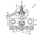
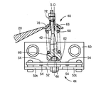
図1は、本発明の一実施例であるペダル操作量検出装置10が設けられた車両の常用ブレーキ用の操作ペダル装置8を示す図で、車両搭載状態において車両の左側から見た左側面図である。図2は、図1におけるII-II矢視部分の拡大断面図で、図3は、図1に示す初期状態のペダル操作量検出装置10を拡大して示した断面図である。また、図4は、操作ペダル16が踏込み操作された状態の図1に対応する左側面図で、図5は図4におけるV-V矢視部分の拡大断面図、図6は図4の状態のペダル操作量検出装置10を拡大して示した図で、図3に対応する断面図である。
この操作ペダル装置8は、図示しないペダルサポートに略水平な支持軸14の軸心まわりに回動可能に配設された操作ペダル16を備えている。支持軸14の軸心は支持軸心に相当する。操作ペダル16は、制動要求に応じて運転者により足踏み操作されるもので、下端部にはペダルシート等の踏部18が設けられているとともに、中間部分には揺動アーム20を介してブレーキブースタのオペレーティングロッド22が連結されている。操作ペダル16は、踏部18にペダル操作力Fが加えられる入力部材で、且つそのペダル操作力Fをオペレーティングロッド22側へ伝達する伝達部材に相当し、オペレーティングロッド22は、操作ペダル16から揺動アーム20を介してペダル操作力Fが伝達されるとともに、そのペダル操作力Fに対応するブレーキ反力Rがブレーキブースタによって作用させられる出力部材に相当する。なお、電気的にホイールブレーキを制御するバイワイヤ方式の操作ペダル装置の場合には、反力機構等によって所定の反力が作用させられる反力部材がオペレーティングロッド22の代りに連結される。
揺動アーム20は、支持軸14と平行な支持ピン32の軸心まわりに揺動可能に操作ペダル16に配設されている。この揺動アーム20は、操作ペダル16に沿って上方へ延びているとともに、操作ペダル16の両側に平行に配設される一対の側板部20a、20bを備えており、それ等の側板部20a、20bに跨がって支持ピン32と平行に円筒形状のカラー34が配設されている。操作ペダル16には、カラー34が所定の遊びを有する状態で挿通させられる円形のストッパ穴36が設けられており、その遊びによって揺動アーム20の揺動が許容されるとともに、カラー34がストッパ穴36の内壁面に当接させられることによって揺動範囲が規定される。支持ピン32の軸心は揺動アーム20の揺動軸心に相当し、ストッパ穴36は、操作ペダル16に対する揺動アーム20の揺動を規制するストッパとして機能する。
前記オペレーティングロッド22の端部には、ねじ結合等により二股状(U字形状)のクレビス24が一体的に固設されているとともに、前記支持ピン32と平行に円柱形状のクレビスピン26が配設されている。そして、このクレビスピン26が前記カラー34内を相対回転可能に挿通させられることにより、オペレーティングロッド22が揺動アーム20に対して相対回動可能に連結され、図4に示すように操作ペダル16が踏込み操作されると、前記ブレーキ反力Rに応じて揺動アーム20を支持ピン32の右まわりに揺動させる力がオペレーティングロッド22から揺動アーム20に加えられる。カラー34は、例えば揺動アーム20の一対の側板部20a、20bに一体的に固設される。クレビスピン26は連結ピンに相当する。
上記オペレーティングロッド22は、操作ペダル16に沿って上方へ延び出す揺動アーム20の基端側部分、すなわち支持ピン32の近傍部分に連結されている一方、揺動アーム20の先端は回動連結部40を介して中継ロッド42に相対回動可能に連結されているとともに、その中継ロッド42は荷重センサ44の受圧部46に当接させられている。したがって、前記ブレーキ反力Rは、揺動アーム20のレバー比に応じて低減されて荷重センサ44に伝達される。前記ペダル操作量検出装置10は、これ等の揺動アーム20、中継ロッド42、荷重センサ44等を含んで構成されている。
荷重センサ44は、ブラケット50を介して操作ペダル16に取り付けられた起歪体52と、その起歪体52の歪すなわち前記ブレーキ反力Rに応じて変形する起歪体52の変形量を検出する歪ゲージ等の歪センサ54とを備えている。起歪体52は、撓み変形が可能な長手状板材でばね板材等によって構成されており、長手方向が上下方向すなわち操作ペダル16の回動方向に対して略直角な方向となり、且つ操作ペダル16の回動平面に対して略垂直(図1の紙面に対して垂直)になる姿勢で、その長手方向の両端部(上下の両端部)がブラケット50にリベット等により一体的に固定されている。ブラケット50には、略直角に折り曲げられた一対の縦壁部50tが設けられており、起歪体52はその縦壁部50tに固定されている。歪センサ54は、例えばブリッジ回路を形成するように複数取り付けられており、起歪体52の変形量に応じた検出信号が出力される。起歪体52の変形量はブレーキ反力Rに対応し、そのブレーキ反力Rは操作ペダル16のペダル操作力Fに応じて変化するため、この検出信号に基づいて、例えば予め定められた換算式やマップからペダル操作力Fやペダルストロークなどのペダル操作量が求められる。
前記受圧部46は、先端に半球形状の凸係合面60が設けられた円柱状の部材によって構成されており、その軸心Oが起歪体52の板面に対して略垂直になる姿勢で、その起歪体52の長手方向の中央部分にねじ締結等により一体的に固設されている。一方、この受圧部46に当接させられる前記中継ロッド42の一端部には、受圧部46の上記凸係合面60に摺動可能に係合させられる凹形状のテーパ面62が設けられており、これ等の凸係合面60とテーパ面62との係合により中継ロッド42が受圧部46に対して揺動可能、厳密には凸係合面60の球中心を中心として揺動可能とされている。凸係合面60の球中心は、円柱状の受圧部46の軸心O上に位置しており、テーパ面62は中継ロッド42の中心線Sと同心に設けられている。テーパ面62のテーパ角度は60°~140°程度の範囲内で、凸係合面60の球半径等を考慮して適宜定められ、本実施例では約120°である。
中継ロッド42の一端部、すなわち上記テーパ面62が設けられた荷重センサ44側の端部には、段差状のばね受け座64が一体に設けられている一方、他端部にはばね受け部材66が配設されており、それ等のばね受け座64とばね受け部材66との間に圧縮コイルスプリング68が配設されている。ばね受け部材66には、円筒部70が同心に一体に設けられて、その円筒部70内を中継ロッド42が貫通させられており、ばね受け部材66はその中継ロッド42の中心線Sに沿って移動可能とされているとともに、中継ロッド42の先端部にはストッパとしてロックナット72が取り付けられ、ばね受け部材66の移動端が規定されている。ばね受け部材66がロックナット72に当接する移動端(初期位置)に保持された状態で、そのばね受け部材66とばね受け座64との間に圧縮コイルスプリング68が所定の圧縮荷重を有する状態で配置されている。
上記ばね受け部材66は、中継ロッド42と一体的に前記受圧部46に対して揺動させられるとともに、前記回動連結部40を介して揺動アーム20に相対回動可能に連結されている。具体的には、ばね受け部材66には部分球面形状の凸係合面74が形成されている一方、揺動アーム20の先端部には、その凸係合面74に摺動可能に係合させられる凹形状のテーパ面76が形成された連結凹部78が一体に設けられており、これ等の凸係合面74とテーパ面76との係合により中継ロッド42と揺動アーム20とが揺動可能、厳密には凸係合面74の球中心を中心として揺動可能とされている。凸係合面74の球中心は中継ロッド42の中心線S上に位置している。ばね受け部材66の凸係合面74が形成された部分は連結凸部に相当し、その連結凸部と連結凹部78とによって回動連結部40が構成されている。連結凹部78には、ばね受け部材66の円筒部70が遊びを持って挿通させられる挿通穴80が設けられており、この遊びによって凸係合面74とテーパ面76との係合を維持しつつ中継ロッド42と揺動アーム20とが揺動可能とされている。上記テーパ面76のテーパ角度は60°~140°程度の範囲内で、凸係合面74の球半径等を考慮して適宜定められ、本実施例では約90°である。
上記中継ロッド42は、例えば操作ペダル16が踏込み操作される前の図1、図3に示す初期状態において、前記オペレーティングロッド22と略平行で、受圧部46の軸心Oと中継ロッド42の中心線Sとが略一致する姿勢となるように、各部の寸法等が定められる。そして、操作ペダル16が踏込み操作されると、揺動アーム20の揺動に伴って回動連結部40が相対回動させられるとともに受圧部46に対して中継ロッド42が揺動させられることにより、図4、図6に示すように中継ロッド42は支持軸14側へ傾動させられる。なお、初期状態において、図7に示すように中継ロッド42が支持軸14と反対側へ傾斜する姿勢に保持され、操作ペダル16が踏込み操作されることにより、図3の状態に変化し、更に図6のように反対側(支持軸14側)へ傾動させられるようにすることもできる。
このようなペダル操作量検出装置10においては、ペダル操作力Fに応じて操作ペダル16が図4に示すように支持軸14の右まわりに回動させられ、そのペダル操作力Fに対応するブレーキ反力Rがオペレーティングロッド22からクレビスピン26およびカラー34を介して揺動アーム20に加えられると、その揺動アーム20は、図6に矢印Aで示されるようにブレーキ反力Rに応じて圧縮コイルスプリング68を弾性変形(圧縮変形)させつつ操作ペダル16に対して揺動させられる。また、その揺動アーム20に回動連結部40を介して相対回動可能に連結された中継ロッド42は、その揺動アーム20の揺動に伴って受圧部46に対して揺動させられ、図6に矢印Bで示す右方向すなわち支持軸14側へ傾動させられる。そして、上記揺動アーム20から圧縮コイルスプリング68および中継ロッド42を介して荷重センサ44にブレーキ反力Rが伝達されると、そのブレーキ反力Rに対応するペダル操作力Fやペダルストロークなどのペダル操作量が検出される。
ここで、本実施例では、揺動アーム20と中継ロッド42とが回動連結部40を介して相対回動可能に連結され、揺動アーム20の揺動に伴って中継ロッド42が受圧部46に対して揺動させられる一方、その中継ロッド42の一端部には凹形状のテーパ面62が設けられ、受圧部46に設けられた半球形状の凸係合面60に摺動可能に係合させられて揺動可能とされているため、揺動アーム20の揺動に拘らず摩擦やこじりが抑制され、中継ロッド42を介してペダル操作量を高い精度で検出することができる。
特に、受圧部46に半球形状の凸係合面60が設けられて中継ロッド42にテーパ面62が設けられているため、図8に示すように中継ロッド42の端部を半球状の凸係合面90として受圧部46に設けられたテーパ面92と係合させる場合に比較して、揺動中心である球中心を荷重センサ44に接近させることが可能で、中継ロッド42の揺動時に受圧部46から荷重センサ44に加えられる荷重の入力位置のずれ量が小さくなり、検出精度を更に向上させることができる。すなわち、中継ロッド42の揺動中心である凸係合面60の球中心から起歪体52までの寸法T(図6参照)を、図8に示すように中継ロッド42側に凸係合面90を設けた場合の寸法tに比較して小さくできるため、中継ロッド42の傾斜角度が同じであれば起歪体52に加えられるこじりモーメントが小さくなり、高い検出精度が安定して得られるようになるのである。
また、受圧部46に設けられた半球形状の凸係合面60に中継ロッド42のテーパ面62が係合させられ、両者がリング状に線接触させられるため、球面同士の係合による揺動に比較して、連続的な滑りにより滑らかに揺動させられるようになって高い検出精度が安定して得られる。すなわち、球面同士の係合の場合には、加工誤差等を考慮して凹形状の球半径が凸形状側よりも大き目とされるため、両球面は点接触させられ、転がりと滑りを繰り返しながら揺動させられる可能性があり、検出精度にばらつきが生じ易い。
また、揺動アーム20と中継ロッド42とを相対回動可能に連結する回動連結部40についても、部分球面形状の凸係合面74がばね受け部材66に設けられ、その凸係合面74に揺動アーム20のテーパ面76が係合させられるようになっているため、両者がリング状に線接触させられて滑らかに相対回動させられるようになり、高い検出精度が安定して得られる。
以上、本発明の実施例を図面に基づいて詳細に説明したが、これはあくまでも一実施形態であり、本発明は当業者の知識に基づいて種々の変更、改良を加えた態様で実施することができる。
8:操作ペダル装置 10:ペダル操作量検出装置 16:操作ペダル(伝達部材) 20:揺動アーム 40:回動連結部 42:中継ロッド 44:荷重センサ 46:受圧部 60:凸係合面 62:テーパ面 66:ばね受け部材(連結凸部) 74:凸係合面 76:テーパ面 78:連結凹部 F:ペダル操作力
Claims (2)
- ペダル操作力を伝達する伝達部材と、
該伝達部材に揺動可能に配設された揺動アームと、
前記伝達部材と前記揺動アームとの間に介在させられて前記ペダル操作力を伝達する中継ロッドと、
前記伝達部材に配設されるとともに、前記ペダル操作力に応じて前記中継ロッドに相対的に押圧される受圧部を備えている荷重センサと、
を有するペダル操作量検出装置において、
前記揺動アームと前記中継ロッドとを相対回動可能に連結する回動連結部を有し、該揺動アームの揺動に伴って該中継ロッドが前記受圧部に対して揺動させられる一方、
前記受圧部は、部分球面形状の凸係合面を有するとともに、前記中継ロッドの一端部には該凸係合面に摺動可能に係合させられる凹形状のテーパ面が設けられており、該凸係合面と該テーパ面との係合により該中継ロッドが該受圧部に対して揺動可能とされている
ことを特徴とするペダル操作量検出装置。 - 前記回動連結部は、
前記揺動アームおよび前記中継ロッドの何れか一方に設けられた、部分球面形状の凸係合面を有する連結凸部と、
前記揺動アームおよび前記中継ロッドの他方に設けられ、前記連結凸部の前記凸係合面に摺動可能に係合させられる凹形状のテーパ面が形成された連結凹部と、を備えている
ことを特徴とする請求項1に記載のペダル操作量検出装置。
Applications Claiming Priority (2)
| Application Number | Priority Date | Filing Date | Title |
|---|---|---|---|
| JP2014-154340 | 2014-07-29 | ||
| JP2014154340A JP6178765B2 (ja) | 2014-07-29 | 2014-07-29 | ペダル操作量検出装置 |
Publications (1)
| Publication Number | Publication Date |
|---|---|
| WO2016017656A1 true WO2016017656A1 (ja) | 2016-02-04 |
Family
ID=55217555
Family Applications (1)
| Application Number | Title | Priority Date | Filing Date |
|---|---|---|---|
| PCT/JP2015/071419 Ceased WO2016017656A1 (ja) | 2014-07-29 | 2015-07-28 | ペダル操作量検出装置 |
Country Status (2)
| Country | Link |
|---|---|
| JP (1) | JP6178765B2 (ja) |
| WO (1) | WO2016017656A1 (ja) |
Citations (5)
| Publication number | Priority date | Publication date | Assignee | Title |
|---|---|---|---|---|
| JP2000198429A (ja) * | 1998-11-05 | 2000-07-18 | Toyota Motor Corp | ブレ―キ操作力検出器を備えたブレ―キ操作装置 |
| JP2001018768A (ja) * | 1999-07-02 | 2001-01-23 | Toyota Motor Corp | ブレーキ操作力検出装置およびブレーキ操作装置 |
| JP2001247020A (ja) * | 2000-03-07 | 2001-09-11 | Aisin Seiki Co Ltd | 車両用ブレーキ装置 |
| JP2005239121A (ja) * | 2004-01-28 | 2005-09-08 | Denso Corp | ペダル踏力検出装置 |
| JP2013097497A (ja) * | 2011-10-31 | 2013-05-20 | Toyoda Iron Works Co Ltd | ペダル操作量検出装置 |
Family Cites Families (1)
| Publication number | Priority date | Publication date | Assignee | Title |
|---|---|---|---|---|
| JP2014115747A (ja) * | 2012-12-07 | 2014-06-26 | Staf Corp | ジョイスティック |
-
2014
- 2014-07-29 JP JP2014154340A patent/JP6178765B2/ja active Active
-
2015
- 2015-07-28 WO PCT/JP2015/071419 patent/WO2016017656A1/ja not_active Ceased
Patent Citations (5)
| Publication number | Priority date | Publication date | Assignee | Title |
|---|---|---|---|---|
| JP2000198429A (ja) * | 1998-11-05 | 2000-07-18 | Toyota Motor Corp | ブレ―キ操作力検出器を備えたブレ―キ操作装置 |
| JP2001018768A (ja) * | 1999-07-02 | 2001-01-23 | Toyota Motor Corp | ブレーキ操作力検出装置およびブレーキ操作装置 |
| JP2001247020A (ja) * | 2000-03-07 | 2001-09-11 | Aisin Seiki Co Ltd | 車両用ブレーキ装置 |
| JP2005239121A (ja) * | 2004-01-28 | 2005-09-08 | Denso Corp | ペダル踏力検出装置 |
| JP2013097497A (ja) * | 2011-10-31 | 2013-05-20 | Toyoda Iron Works Co Ltd | ペダル操作量検出装置 |
Also Published As
| Publication number | Publication date |
|---|---|
| JP2016031680A (ja) | 2016-03-07 |
| JP6178765B2 (ja) | 2017-08-09 |
Similar Documents
| Publication | Publication Date | Title |
|---|---|---|
| JP5492360B2 (ja) | ペダル操作量検出装置 | |
| JP5455851B2 (ja) | ペダル操作量検出装置 | |
| JP5553804B2 (ja) | ペダル操作量検出装置 | |
| JP5619054B2 (ja) | ペダル操作量検出装置 | |
| JP7255502B2 (ja) | 車両用ペダル装置 | |
| JP5429189B2 (ja) | 操作量検出装置 | |
| JP4989714B2 (ja) | 操作量検出装置 | |
| JP6178765B2 (ja) | ペダル操作量検出装置 | |
| JP2000326754A (ja) | 自動車用アクセルペダル装置 | |
| JP6510467B2 (ja) | ペダル踏力検出装置 | |
| JP5331070B2 (ja) | ペダル操作量検出装置 | |
| JP6670265B2 (ja) | 車両用操作ペダル装置 | |
| JP6212060B2 (ja) | 車両用ペダル操作力検出装置 | |
| JP6122408B2 (ja) | 車両用ペダル操作力検出装置 | |
| JP2022146307A (ja) | 車両用操作ペダル装置 | |
| JP2011154497A (ja) | 車両等操縦用ジョイスティック装置 |
Legal Events
| Date | Code | Title | Description |
|---|---|---|---|
| 121 | Ep: the epo has been informed by wipo that ep was designated in this application |
Ref document number: 15826767 Country of ref document: EP Kind code of ref document: A1 |
|
| NENP | Non-entry into the national phase |
Ref country code: DE |
|
| 122 | Ep: pct application non-entry in european phase |
Ref document number: 15826767 Country of ref document: EP Kind code of ref document: A1 |