WO2016017609A1 - 注射針廃棄用容器 - Google Patents
注射針廃棄用容器 Download PDFInfo
- Publication number
- WO2016017609A1 WO2016017609A1 PCT/JP2015/071308 JP2015071308W WO2016017609A1 WO 2016017609 A1 WO2016017609 A1 WO 2016017609A1 JP 2015071308 W JP2015071308 W JP 2015071308W WO 2016017609 A1 WO2016017609 A1 WO 2016017609A1
- Authority
- WO
- WIPO (PCT)
- Prior art keywords
- holding
- needle
- injection needle
- holding part
- moving member
- Prior art date
- Legal status (The legal status is an assumption and is not a legal conclusion. Google has not performed a legal analysis and makes no representation as to the accuracy of the status listed.)
- Ceased
Links
Images








Classifications
-
- A—HUMAN NECESSITIES
- A61—MEDICAL OR VETERINARY SCIENCE; HYGIENE
- A61B—DIAGNOSIS; SURGERY; IDENTIFICATION
- A61B50/00—Containers, covers, furniture or holders specially adapted for surgical or diagnostic appliances or instruments, e.g. sterile covers
- A61B50/30—Containers specially adapted for packaging, protecting, dispensing, collecting or disposing of surgical or diagnostic appliances or instruments
- A61B50/36—Containers specially adapted for packaging, protecting, dispensing, collecting or disposing of surgical or diagnostic appliances or instruments for collecting or disposing of used articles
- A61B50/362—Containers specially adapted for packaging, protecting, dispensing, collecting or disposing of surgical or diagnostic appliances or instruments for collecting or disposing of used articles for sharps
-
- A—HUMAN NECESSITIES
- A61—MEDICAL OR VETERINARY SCIENCE; HYGIENE
- A61M—DEVICES FOR INTRODUCING MEDIA INTO, OR ONTO, THE BODY; DEVICES FOR TRANSDUCING BODY MEDIA OR FOR TAKING MEDIA FROM THE BODY; DEVICES FOR PRODUCING OR ENDING SLEEP OR STUPOR
- A61M5/00—Devices for bringing media into the body in a subcutaneous, intra-vascular or intramuscular way; Accessories therefor, e.g. filling or cleaning devices, arm-rests
- A61M5/178—Syringes
- A61M5/31—Details
- A61M5/32—Needles; Details of needles pertaining to their connection with syringe or hub; Accessories for bringing the needle into, or holding the needle on, the body; Devices for protection of needles
- A61M5/3205—Apparatus for removing or disposing of used needles or syringes, e.g. containers; Means for protection against accidental injuries from used needles
-
- A—HUMAN NECESSITIES
- A61—MEDICAL OR VETERINARY SCIENCE; HYGIENE
- A61B—DIAGNOSIS; SURGERY; IDENTIFICATION
- A61B50/00—Containers, covers, furniture or holders specially adapted for surgical or diagnostic appliances or instruments, e.g. sterile covers
- A61B2050/005—Containers, covers, furniture or holders specially adapted for surgical or diagnostic appliances or instruments, e.g. sterile covers with a lid or cover
Definitions
- the present invention relates to a syringe needle disposal container for removing a used syringe needle from the syringe body and discarding it.
- syringes used in hospitals include a screw type in which a needle holding member of an injection needle is detachably screwed to the distal end portion of the syringe body.
- a needle holding member of an injection needle is detachably screwed to the distal end portion of the syringe body.
- a syringe is discarded after being separated into a syringe body and a needle.
- his / her finger may be accidentally damaged by the injection needle.
- This syringe needle disposal container includes a container main body for storing medical waste and a lid that covers the opening of the container main body, and a moving member moves to the mounting portion of the lid via a slide mechanism. It is supported freely.
- One end portion of the mounting portion is provided with a first holding portion for holding one side of the needle holding member of the injection needle, and the moving member has a first holding portion for holding the other side of the needle holding member of the injection needle. 2 holding parts are provided.
- the moving member When discarding the injection needle in the injection needle disposal container, first, the moving member is moved in a predetermined direction toward the first holding portion on the lid side to the holding position, and the first holding portion on the lid side and the first holding portion on the moving member side are moved.
- the second holding part constitutes the injection needle holding part. Then, the needle holding member of the injection needle is inserted into the injection needle holding portion, and in this state, the syringe body is rotated in the detaching direction to remove the needle holding member from the syringe body, and then the moving member is moved to the retracted position.
- the second holding portion of the moving member is separated from the needle holding member of the injection needle, and the needle holding member (that is, the injection needle) held by the first holding portion of the lid body passes through the drop opening of the lid body by its own weight. It falls and is stored in the container body.
- the above-described needle disposal container has the following problems to be solved.
- the first holding part on the lid side and the second holding part on the moving member side constitute an injection needle holding part.
- the lid side The opening end of the first holding part, that is, the split axis of the needle holding part is an axis passing through the center of the injection needle holding part and coincides with an axis extending in a direction perpendicular to the sliding direction of the moving member.
- the injection needle holding part is formed over the entire circumference. Therefore, when the moving member is moved toward the retracted position, the needle holding member (that is, the injection needle) is not detached from the predetermined holding portion, and this needle holding member tends to remain in the predetermined holding portion.
- An object of the present invention is to provide a container for discarding a syringe needle that can be easily removed from the syringe body and stored in the container body.
- the container for discarding an injection needle discards an injection needle having a needle holding member that is detachably screwed to a distal end portion of a syringe main body and a needle main body held by the needle holding member.
- a needle disposal container for A container main body for storing waste, a lid that covers the opening of the container main body, and a moving member that is slidably mounted in a predetermined direction on a mounting portion provided on the lid via a slide mechanism And a first holding part for holding one side of the needle holding member of the injection needle is provided at one end of the mounting part, and the first holding part is dropped in relation to the first holding part.
- the moving member is provided with a second holding portion for holding the other side of the needle holding member of the injection needle,
- the moving member moves in a direction approaching the first holding portion, and the first holding portion on the lid side and the second on the moving member side.
- the holding portion constitutes an injection needle holding portion for holding the injection needle in cooperation with each other, and when the moving member is moved away from the first holding portion, the injection needle holding portion is It is configured to be open and to allow the injection needle to drop through the drop opening of the mounting portion, Furthermore, the opening end of the first holding portion on the lid side passes through the center of the injection needle holding portion in the holding position state and is substantially perpendicular to the reference central axis that is substantially perpendicular to the sliding movement direction of the moving member. The first holding unit is shifted from the first holding unit.
- the amount of deviation D of the opening end of the first holding part on the lid side from the reference central axis is determined by the needle holding of the injection needle.
- the outer diameter of the member is d, it is (0.1 to 0.4) d (0.1d ⁇ D ⁇ 0.4d).
- a holding region that engages with the injection needle and an engagement with the injection needle are provided on an inner peripheral surface of the second holding portion on the moving member side.
- region which is not carried out is provided.
- the non-holding region is an open end that protrudes toward the first holding part from the reference central axis in the second holding part on the moving member side. It is provided in the part.
- the holding region is an engagement protrusion that engages with the injection needle, and the engagement protrusion is formed on an outer peripheral surface of the injection needle. It has a height that engages with the formed vertical rib, and is shaped so that no force in the sliding direction is applied to the vertical rib on the outer peripheral surface of the injection needle when the moving member slides.
- a syringe needle disposal container comprising: a needle holding member that is detachably screwed to a distal end portion of a syringe main body; and an injection needle having a needle main body held by the needle holding member.
- a needle disposal container for disposal A container body for containing waste, and a lid that covers the opening of the container body
- the lid body is provided with a first holding portion for holding one side of the needle holding member of the injection needle, and a slidably movable in a direction away from the first holding portion, and the lid holding member of the needle holding member of the injection needle Holding the other side, and having a second holding part that forms a needle drop opening with the first holding part by sliding in a direction away from the first holding part,
- the second holding part moves in a direction approaching the first holding part
- the first holding part and the second holding part are: When the second holding part is moved away from the first holding part, the injection needle holding part is opened.
- the syringe needle is configured to be allowed to drop through the drop opening; Furthermore, the second holding portion and the first holding portion have a holding region that engages with the injection needle, The second holding portion and / or the first holding portion on the lid side of the moving member has a non-holding region that does not engage with the injection needle.
- the holding region is an engagement protrusion that engages with the injection needle, and the engagement protrusion is formed on an outer peripheral surface of the injection needle. It has a height that engages with the formed vertical rib, and is shaped so that no force in the sliding direction is applied to the vertical rib on the outer peripheral surface of the injection needle when the moving member slides. It is characterized by.
- an injection needle disposal container includes a needle holding member that is detachably screwed to a distal end portion of a syringe main body, and an injection needle having a needle main body held by the needle holding member.
- a needle disposal container for disposal A container body for containing waste, and a lid that covers the opening of the container body
- the lid body is provided with a first holding portion for holding one side of the needle holding member of the injection needle, and a slidably movable in a direction away from the first holding portion, and the lid holding member of the needle holding member of the injection needle Holding the other side, and having a second holding part that forms a needle drop opening with the first holding part by sliding in a direction away from the first holding part,
- the second holding part moves in a direction approaching the first holding part
- the first holding part and the second holding part are: When the second holding part is moved away from the first holding part, the injection needle holding part is opened.
- the syringe needle is configured to be allowed to drop through the drop opening; Furthermore, the open end of the first holding part passes through the center of the injection needle holding part in the holding position state and is substantially perpendicular to the sliding movement direction of the second holding part, It is characterized by being shifted to the first holding part side.
- the present invention it is possible to provide a container for discarding a syringe needle that can be easily removed from the syringe body and stored in the container body.
- a needle disposal container 2 includes a container body 4 for storing medical waste such as a used injection needle or absorbent cotton.
- the container body 4 has a box shape with an open upper surface, and the upper surface opening 6 of the container body 4 is covered with a plate-like lid body 8.
- a cover body 10 for covering the upper surface of the lid body 8 is attached to the rear side portion of the lid body 8 via a hinge 12 so as to be freely opened and closed.
- a hook 14 is provided at the tip of the cover body 10, and a receiving recess 16 is provided in the lid body 8 corresponding to the hook 14, and the hook 14 is detachably received in the receiving recess 16.
- the lid body 8 is provided with a rectangular charging opening 18. For example, used absorbent cotton or the like is charged into the container body 4 through the charging opening 18.
- the injection needle disposal container 2 is configured as follows so that the injection needle 26 of a screw type syringe 24 (for example, an insulin syringe) can be discarded.
- this screw type syringe 24 includes a syringe body 28, and a syringe needle 26 is screwed to the distal end portion of the syringe body 28 (FIGS. 1 and FIG. 1). 10).
- a small-diameter projection 30 is provided at the distal end of the syringe body 28, a needle attachment portion 32 is provided at the distal end of the small-diameter projection 30, and a male screw portion 34 is provided on the outer peripheral surface of the needle attachment portion 32. .
- the injection needle 26 has a cylindrical needle holding member 36 (so-called hub) and a needle body 38 held by the needle holding member 36, and penetrates an end wall (not shown) of the needle holding member 36. Thus, the needle body 38 is held.
- a female screw portion (not shown) is provided on the inner peripheral surface of the needle holding member 36 corresponding to the male screw portion 34 on the syringe body 28 side. Since it is configured in this manner, the internal thread portion of the injection needle 26 can be screwed onto the external thread portion 34 of the syringe body 28 to attach the injection needle 26 to the syringe body 28 and can be used as the syringe 24. In this state, the injection needle 26 can be removed from the syringe body 28 by rotating the injection needle 26 in the direction of detachment.
- a plurality of engagement recesses 40 (16 in this embodiment as shown in FIG. 10) are provided on the outer peripheral surface of the needle holding member 36 of the injection needle 26 at substantially equal intervals in the circumferential direction.
- the plurality of engaging recesses 40 are provided so as to extend linearly in the axial direction of the needle holding member 36 (the vertical direction in FIGS. 10 and 11). Longitudinal ribs are formed between the engaging recesses 40, and these longitudinal ribs are provided on the outer peripheral surface of the needle holding member 36 in the circumferential direction.
- the lid 8 on the container body 4 side is provided with a mounting portion 44, and the mounting portion 44 is provided with a rectangular mounting recess 46 (see FIG. 2).
- the mounting recess 46 is formed on the upper surface of the lid 8, and a plate-like moving member 48 is mounted on the mounting recess 46 so as to be slidable along the mounting recess 46.
- On both sides of the moving member 48 a pair of mounting claws extending in the sliding direction of the moving member 48 (left and right in FIGS. 3 to 6, 10 and 11, and perpendicular to the paper surface in FIG. 7). 50 is provided.
- a pair of mounting openings 52 are provided on both sides of the mounting recess 46 corresponding to the pair of mounting claws 50, and these mounting openings 52 extend in the sliding movement direction.
- a pair of mounting claws 50 on the moving member 48 side is slidably engaged with the edge of the mounting opening 52 through the pair of mounting openings 52 (see FIG. 7).
- the pair of mounting claws 50 and the pair of mounting openings 52 constitute a slide mechanism 53 (see FIG. 7), and the movable member 48 is held by the slide mechanism 53 (see FIGS. 3, 5, and 5).
- 8 and FIG. 10 which is a position where the injection needle 26 is held as will be described later, and a retracted position which is retracted from this holding position (the position shown in FIGS. 4, 6, 11). And a position where the holding state of the needle 26 is released).
- a substantially semi-cylindrical first holding portion 54 is provided at one end of the mounting portion 44 of the lid 8, specifically, one end of the mounting recess 46. , And extends downward into the container body 4.
- a first holding recess 56 is provided at the upper end of the inner peripheral surface of the first holding portion 54 (that is, a substantially semicircular arc-shaped inner surface), and the first holding recess 56 is a small-diameter protrusion of the syringe body 28.
- the member 36 has a shape corresponding to the shape of the plurality of engaging recesses 40 (see FIGS. 8, 10, and 11), protrudes inward in the radial direction of the first holding portion 54, and is an upper portion of the first holding portion 54. Extends downward from the bottom to the bottom. A region where the plurality of engaging protrusions 60 are provided functions as a holding region.
- a drop opening 62 is provided on one end side of the mounting recess 46 (in this embodiment, on the first holding portion 54 side), and the drop opening 62 has a parabolic shape from one end of the mounting recess 46 to the vicinity of the center thereof. It extends to.
- a substantially semi-cylindrical second holding portion 64 is provided at one end portion of the moving member 48 (that is, the end portion on the first holding portion 54 side). It extends downward into the main body 4.
- a second holding recess 66 is provided on the upper side of the inner peripheral surface of the second holding portion 64 (that is, the substantially semicircular arc-shaped inner surface), and the second holding recess 66 is a small-diameter protrusion of the syringe body 28.
- a large part of the inner peripheral surface of the second holding part 64 is provided with a plurality of engaging protrusions 70 at intervals in the circumferential direction, and the plurality of engaging protrusions 70 are provided for holding the needle of the injection needle 26.
- the member 36 has a shape corresponding to the shape of the plurality of engaging recesses 40 (see FIGS. 8, 10, and 11), protrudes inward in the radial direction of the second holding portion 64, and is an upper portion of the second holding portion 64. Extends downward from the bottom to the bottom.
- the region in which the plurality of engagement protrusions 70 are provided functions as a holding region, and is between the plurality of engagement protrusions 60 of the first holding portion 54 and the plurality of engagement protrusions 70 of the second holding portion 64. This area becomes a non-holding area where there is no engaging protrusion.
- the moving member 48 when the moving member 48 is positioned at the holding position, one end of the moving member 48 comes into contact with or close to one end of the mounting recess 46, and the first holding portion 54 on the lid 8 side
- the second holding portion 64 on the moving member 48 side cooperates with each other to form a cylindrical injection needle holding portion 72, and the plurality of engaging protrusions 60 and 70 are included in the injection needle holding portion 72.
- Engaging protrusions are arranged on the peripheral surface at intervals (see FIGS. 3, 5, 8, and 10).
- the first holding recess 56 of the first holding portion 54 and the second holding recess 66 of the second holding portion 64 cooperate with each other to removably receive the tip of the small diameter protrusion 30 of the syringe main body 28.
- a holding recess is formed.
- the moving member 48 when the moving member 48 is positioned at the retracted position, the other end of the moving member 48 is in contact with or close to the other end of the mounting recess 46, and the second holding portion 64 is separated from the first holding portion 54.
- the injection needle holder 72 is opened (see FIGS. 4, 6, 9 and 11). The first and second holding portions 54 and 64 will be described in detail later.
- a lock mechanism 76 for holding the moving member 48 in the holding position is provided.
- the locking mechanism 76 includes a tilting member 78 that is tiltably provided at the center of the mounting recess 46 below the moving member 48, and a locking protrusion 80 provided on the lower surface of the moving member 48.
- a locking claw portion 82 protrudes somewhat upward from the distal end portion of the tilting member 78, and a first taper portion 86 is formed at the distal end portion of the locking claw portion 82.
- a second taper portion 84 is formed at the distal end portion of the locking projection 80 so as to correspond to the first taper portion 84 of the locking claw portion 82.
- an inclined surface 88 is provided on a part of the upper surface of the tilting member 78 so as to rise upward from the base end side toward the tip end side (see FIGS. 10 and 11).
- the moving member 48 is provided with an elliptical operation opening 90, and the upper surface (inclined surface 88) of the tilting member 78 is exposed to the outside through the operation opening 90.
- a ring-shaped operation protrusion 92 is provided at the edge of the operation opening 90 so as to protrude somewhat upward.
- the tilting member 78 includes a lock position (indicated by a solid line in FIG. 8) where the locking claw portion 82 engages with the locking projection 80, and a lock release position where the locking claw portion 82 is detached from the locking projection 80. It is possible to tilt up and down between (indicated by a one-dot chain line in FIG. 8).
- the tilting member 78 can be elastically deformed between the locked position and the unlocked position, and is normally held at the locked position.
- a movement opening 94 is provided in the mounting recess 46, and the movement opening 94 extends along the movement path of the locking projection 80.
- a blindfold 96 is provided at the other end of the moving member 48 (the end opposite to the second holding portion 64), and the blindfold 96 extends downward in an L shape. When the moving member 48 is positioned at the holding position, the blindfold 96 covers part of the moving opening 94 of the mounting recess 46 from below.
- a thinning portion 98 is provided between the operation opening 90 and the second holding portion 64. The thinning portion 98 prevents the moving member 48 that has moved to the retracted position from interfering with the upper surface of the tilting member 78 when the moving member 48 is positioned at the retracted position (see FIG. 11).
- the opening end of the first holding portion 54 passes through the center P (see FIG. 8) of the injection needle holding portion 72 configured when the moving member 48 is located at the holding position, and is indicated by an arrow 100.
- the reference center axis L that is substantially perpendicular to the slide movement direction is used as a reference and is shifted to the first holding portion 54 side on the lid 8 side, and the amount of deviation of the opening end from the reference center axis L D (see FIG.
- the injection needle 26 is formed symmetrically with respect to an arbitrary radial axis passing through the center, and its center of gravity is the center P of the injection needle holding portion 72 in a state of being inserted and held in the injection needle holding portion 72. Therefore, as can be understood from FIG. 8, when the moving member 48 is moved to the retracted position, the weight of the injection needle 26 is released from the first holding portion 54 on the lid 8 side. The injection needle 26 can be dropped and accommodated in the container body 4 by using its own weight.
- the first holding portion 54 is further configured as follows. That is, the opening end portions 102 and 104 of the second holding portion 64 on the moving member 48 side extend to the first holding portion 54 side with respect to the reference central axis L, and the inner surfaces of the opening end portions 102 and 104 are directed toward the first holding portion 54 side.
- Engaging protrusions that engage with the plurality of engaging recesses 40 of the needle holding member 36 on the injection needle 26 side are provided on the inner surfaces of the opening end portions 102 and 104.
- the inner surfaces of the open end portions 102 and 104 are non-holding regions.
- the opening end portions 102 and 104 of the second holding portion 64 are configured to expand in the radial direction, and the inner surfaces of the opening end portions 102 and 104 are made flat (in other words, there are engagement protrusions).
- the opening end portions 102 and 104 do not act on the needle holding member 36 of the injection needle 26 held by the first holding portion 54, and the moving member 48 is moved to the holding position. And the retreat position can be smoothly moved.
- the inner surfaces of the opening end portions 102 and 104 of the second holding portion 64 extend radially outward toward the opening end, but instead of such a configuration, the opening end portions 102 and 104 face the opening end.
- a straight line may be provided in the tangential direction, or a recess may be provided to extend linearly toward the opening end (see FIGS. 12 and 13 described later).
- the moving member 48 is positioned at the holding position. Then, as shown in FIG. 10, the locking claw portion 82 of the tilting member 78 engages with the locking projection 80 on the lid body 8 side, and the locking mechanism 76 is locked, and the moving member 48 holds the above-mentioned holding member.
- the first holding part 54 on the lid 8 side and the second holding part 64 on the moving member 48 side constitute an injection needle holding part 72.
- the needle holding member 36 of the used injection needle 26 is inserted into the injection needle holding portion 72 (see FIG. 10).
- the tip of the small-diameter projection 30 of the syringe main body 28 is inserted into the holding recess of the injection needle holding portion 72 (the first holding recess 56 of the first holding portion 54 and the second holding recess 66 of the second holding portion 64).
- the injection needle 26 is held by the injection needle holding portion 72.
- the plurality of engaging protrusions 60 and 70 of the first and second holding portions 54 and 64 are held in a state of being engaged with the plurality of engaging recesses 40 on the outer peripheral surface of the injection needle holding member 36.
- the syringe main body 28 is rotated with respect to the injection needle 26 in the detaching direction indicated by the arrow R in FIG.
- the syringe main body 28 is released from the needle holding member of the injection needle 26. 36 is removed.
- the moving member 48 is locked and held in the holding position by the lock mechanism 76, the moving member 48 slides to the retracted position when the syringe body 28 is rotated relative to the injection needle 26. There is no movement.
- the user inserts the fingertip into the operation opening 90, presses the upper surface of the tilting member 78 downward, and tilts the tilting member 78 downward to lock the locking claw 82 and the locking protrusion on the lid 8 side.
- 80 is released (that is, the locked state of the lock mechanism 76 is released), and the movable member 48 is moved from the holding position by hooking the fingertip onto the operation projection 92 in the unlocked state. Slide to the retracted position.
- the second holding portion 64 on the moving member 48 side is held by the first holding portion 54 on the lid body 8 side (that is, the needle holding member 36).
- the needle 26 is tilted toward the moving member 48 by its own weight, the needle holding member 36 is detached from the first holding part 54, and the released injection needle 26 enters the container body 4 through the drop opening 62. Fallen and contained.
- the injection needle 26 removed from the syringe main body 28 can be accommodated in the container main body 4 by a simple operation of using the dead weight of the injection needle 26 and moving the moving member 48 to the retracted position.
- the moving member 48 After collecting the injection needle 26 in the container body 4, the moving member 48 is slid from the retracted position to the holding position as the next collection preparation. At this time, the first taper portion 84 of the locking claw portion 82 slides on the second taper portion 86 of the locking projection portion 80, whereby the tilting member 78 is tilted downward, and the locking claw portion 82 is moved. The locking projection 76 is engaged, and thus the locking mechanism 76 is locked, and the moving member 48 is locked and held at the holding position.
- the second holding portion 64 on the moving member 48 side is provided with a plurality of engaging protrusions 70 over an area from the bottom portion to the reference central axis L, that is, an angle range of 180 degrees. Since these engaging protrusions 70 protrude radially inward, when the amount of protrusion increases, the engaging member 70 is held by the moving member 48 when the moving member 48 is moved toward the retracted position. There is a risk that the injection needle 26 (needle holding member 36) moves to the retracted position. Therefore, in order to solve such a problem, it is desirable to configure as shown in FIGS. In this modification, members substantially the same as those in the embodiment shown in FIGS. 1 to 11 are denoted by the same reference numerals, and description thereof is omitted.
- the first bottom region S1 from the bottom of the second holding portion 64A of the moving member 48A to the opening end portion 102A on the one end side to the first predetermined angle ⁇ 1 and the other from the bottom.
- a plurality of engaging protrusions 70 are provided over the bottom regions S1 and S2 to form a holding region.
- the engaging protrusion 70 engages with the engaging recess 40 on the other end side of the needle holding member 36.
- first opening region K1 from the first predetermined angle ⁇ 1 to the opening end of the opening end portion 102A on one end side thereof and the second opening region from the second predetermined angle ⁇ 2 to the opening end of the opening end portion 104A on the other end side.
- the inner surface of the opening region K2 is formed in a flat shape to be a non-holding region, and there are no engaging protrusions that engage with the engaging recesses 40 of the needle holding member 36 in these opening regions K1 and K2.
- the first predetermined angle ⁇ 1 which is the first boundary Q1 between the first bottom region S1 and the first opening region K1 (non-holding region), is preferably 30 to 70 degrees, and preferably 35 to 50 degrees. More preferably, the second predetermined angle ⁇ 2 serving as the second boundary Q2 between the second bottom region S2 and the second opening region K2 (non-holding region) is also preferably 30 to 70 degrees, and preferably 35 to 50 degrees. It is more preferable that
- the present invention when the present invention is applied to an injection needle provided with the needle holding member 36 having 16 engaging recesses 40 at equal intervals in the circumferential direction on the outer peripheral surface, the second holding portion on the moving member 48A side. 64A, there are two engaging protrusions 70 (holding areas) in the first bottom area S1, and there are two engaging protrusions 70 (holding areas) in the second bottom area S2. it can.
- the engagement state between the plurality of engagement recesses 40 of the needle holding member 36 and the engagement protrusions 70 of the second holding portion 64A may not be sufficient, and the first and second predetermined angles ⁇ 1 and ⁇ 2 are If it becomes excessive, the engagement protrusion 70 of the first holding part 64A (particularly, the engagement protrusion 70 located on the opening end side) becomes difficult to disengage from the engagement recess 40 of the needle holding member 36, and the moving member 48A.
- the needle holding member 36 When the needle holding member 36 is moved toward the retracted position, the needle holding member 36 may move toward the retracted position together with the moving member 48A.
- first and second opening regions K1 and K2 of the second holding portion 64A of the moving member 48A are non-holding regions where there are no engaging protrusions, so the second holding portion 64A.
- the inner surfaces of the first and second opening regions K1 and K2 do not act on the needle holding member 36 held by the injection needle holding portion 72A, thereby moving the moving member 48A from the holding position shown in FIG.
- the needle holding member 36 (that is, the injection needle) does not move together with the moving member 48 ⁇ / b> A, and as a result, as described above, the injection needle ( The needle holding member 36) can be reliably dropped and accommodated in the container body using its own weight.
- the first predetermined angle ⁇ 1 and the second predetermined angle ⁇ 2 are set to the same angle.
- the first predetermined angle ⁇ 1 is set to the second angle. It may be set larger (or smaller) than the predetermined angle ⁇ 2.
- a plurality of engagement recesses 40 are provided on the outer peripheral surface of the needle holding member 36 of the injection needle 26, and the first holding portion 54 on the lid 8 side and the second holding portion on the moving member 48 side.
- a plurality of engaging protrusions 60 and 70 are provided on the inner peripheral surface of 64, but, contrary to such a configuration, a plurality of engaging protrusions are provided on the needle holding member 36 side of the injection needle 26, and You may make it provide a some engagement recessed part in the 1st and 2nd holding
- the moving member is slidably mounted between the holding position and the retracted position via the slide mechanism.
- the first holding portion on the lid side and the moving member constitutes an injection needle holding part for holding the needle holding member of the injection needle.
- the moving member is positioned at the holding position, and the needle holding member of the injection needle is inserted and held in the injection needle holding part constituted by the first and second holding parts.
- the first holding part holds one side of the injection needle
- the second holding part on the moving member side holds the other side of the injection needle.
- the opening end of the first holding part on the lid side is shifted to the first holding part side with respect to the reference central axis of the injection needle holding part in the holding position state, so that the moving member is in the retracted position. Is moved to the outside from the first holding part on the lid side to the outside of the needle holding member of the injection needle, and the center of gravity of the injection needle is located outside the first holding part on the lid side. . Accordingly, the weight of the needle holding member held by the first holding part on the lid side easily acts as a force for detaching and dropping, whereby the injection needle detached from the syringe main body can be dropped and accommodated in the container main body.
- the deviation amount D from the reference central axis of the opening end of the first holding portion on the lid side is (0.1 to 0.4) d, where d is the outer diameter of the needle holding member of the injection needle. Therefore, when the moving member is moved to the retracted position, the center of gravity of the injection needle held by the first holding part is a distance (0.1 to 0.4) d outside the opening end of the first holding part. Therefore, due to the distance, the needle holding member held by the first holding part acts as a force for releasing and dropping the needle holding member. Can be dropped and accommodated.
- the outer peripheral surface of the needle holding member of the injection needle is provided with a plurality of engaging recesses (or engaging protrusions) at intervals in the circumferential direction, and the first holding portion on the lid side and the first holding portion on the moving member side. 2 Since a plurality of engagement protrusions (or engagement recesses) are provided at intervals in the circumferential direction on the inner peripheral surface of the holding part, a plurality of engagement recesses (or engagement protrusions) on the needle holding member side are provided. Part) can be latched and held by a plurality of engagement protrusions (or engagement recesses) of the first and second holding parts on the container body side.
- a plurality of engaging recesses are provided on the outer peripheral surface of the needle holding member of the injection needle, and a plurality of engaging protrusions are provided on the inner peripheral surface of the first holding portion on the lid side and the second holding portion on the moving member side. Therefore, it can be provided as a disposal container suitable for discarding the injection needle having such a configuration.
- maintenance part by the side of a moving member spreads linearly (or radial direction outward) toward the 1st holding
- the opening end of the second holding portion acts on the outer peripheral surface of the needle holding member of the injection needle. Therefore, when the moving member is moved to the retracted position, the injection needle removed from the syringe main body is smoothly dropped and accommodated in the container main body.
- a plurality of engaging protrusions are provided across the first bottom region and the second bottom region of the second holding portion, and the first opening region and the second opening portion are provided. Since there are no engaging protrusions in the region, the plurality of engaging protrusions in the first and second bottom regions are in the plurality of engaging recesses in the needle holding member of the injection needle when held in the holding position.
- the outer periphery of the needle holding member of the injection needle in which the plurality of engaging protrusions on the second holding part side are held by the first holding part on the lid body side when securely held by engagement and moved to the retracted position It is possible to prevent the injection needle from being moved to the retracted position by being held by the second holding portion when the moving member is moved to the retracted position without acting on the surface.
- the first predetermined angle that is the first boundary between the first bottom region and the first opening region is 30 to 70 degrees
- the second boundary that is the second boundary between the second bottom region and the second opening region is 30 to 70 degrees
- the locking mechanism is composed of a tilting member on the lid side and a locking projection on the moving member side, and a locking claw is provided at the tip of the tilting member, so that the locking claw of the tilting member moves.
- the moving member can be locked and held at the holding position.
- a fingertip or the like is inserted into the operation opening, and the upper surface of the tilting member is pressed with the fingertip or the like to release the locked state.
- the operation of tilting to the unlocked position and the operation of sliding the moving member to the retracted position by hooking a fingertip or the like on the operation opening can be performed in one operation.
- a holding area that engages with the injection needle and a non-holding area that does not engage with the injection needle are provided on the inner peripheral surface of the second holding portion on the moving member side. For this reason, it is possible to reduce the possibility that the injection needle remains in the second holding portion after the moving member slides to the retracted position.
- the non-holding region is provided in a portion protruding from the reference central axis in the second holding part on the moving member side toward the first holding part. That is, the non-holding region is provided on the opening side in the second holding part. For this reason, after the moving member slides to the retracted position, the injection needle is easily separated from the second holding portion, and is easily dropped and accommodated in the waste container.
- the holding region is an engagement protrusion that engages with the injection needle, and the engagement protrusion has a height that engages with a vertical rib formed on the outer peripheral surface of the injection needle, and the moving member It is shaped so that no force in the sliding direction is applied to the vertical ribs on the outer peripheral surface of the injection needle during sliding. For this reason, when the moving member is slid, there is no situation in which the injection needle slides while being held on the moving member side, and the injection needle can be reliably dropped and accommodated in the waste container body.
- the second holding portion of the moving member and the first holding portion on the lid side have a holding region that engages with the injection needle
- the first holding part on the lid side has a non-holding area that does not engage with the injection needle, the non-holding area is provided on the opening end side of the holding part, and the holding area engages with the injection needle.
- a shape that is shaped so that a force in the sliding direction is not applied can be considered.
- the holding area in the first holding part on the lid side and the second holding part on the moving member side is not applied with a force in the sliding movement direction with respect to the injection needle when the moving member slides. That is, the holding part is formed so as not to hold the injection needle when the moving member slides. Therefore, as the moving member slides, the injection needle is naturally dropped and accommodated in the waste container.
- the opening end of the first holding part on the lid side passes through the center of the injection needle holding part in the holding position state and is substantially perpendicular to the sliding movement direction of the moving member. It does not have to be shifted to the first holding part side with respect to the reference center axis.
- This modification is configured as shown in FIG. 14, for example, so that a force in the sliding direction does not act on the vertical rib of the injection needle when the moving member moves toward the retracted position. That is, the opening side portions 74 and 76 of the non-holding regions K1 and K2 of the second holding portion 64B are configured so that the inner diameter gradually increases toward the opening end, and thereby the opening side portions 74 and 76 of the second holding portion 64B. 76 is formed so as to expand somewhat toward the opening end side rather than a semicircular shape. With this configuration, when the moving member 48B moves toward the retracted position, the inner peripheral surface of the second holding portion 38B does not act on the vertical rib of the injection needle 24. It is possible to prevent the force from the moving member 48B from acting on the.
- each engaging projection 70B provided on the second holding portion 64B has both side surfaces 80, 82 inclined inward toward the tip (ie, radially inward), and each engaging projection 70B. Is formed in a trapezoidal shape.
- the first holding portion is formed at one end of the mounting portion and the second holding portion is formed at one end of the moving member, but the mounting portion has two slidable moving members.
- the first holding part and the second holding part may be formed on each of the two moving members, that is, the injection needle holding part may be formed by a plurality of moving members.
- Injection needle disposal container 4 Container body 8 Lid 26 Injection needle 28 Syringe body 36 Needle holding member 40 Engaging recess 44 Mounting portion 48, 48A, 48B Moving member 50 Mounting claw portion 52 Mounting opening 54 First holding portion 60, 70 engagement protrusion 62 drop opening 64, 64A, 64B second holding portion 72 injection needle holding portion 76 lock mechanism
Landscapes
- Health & Medical Sciences (AREA)
- Engineering & Computer Science (AREA)
- Life Sciences & Earth Sciences (AREA)
- Veterinary Medicine (AREA)
- General Health & Medical Sciences (AREA)
- Biomedical Technology (AREA)
- Heart & Thoracic Surgery (AREA)
- Public Health (AREA)
- Animal Behavior & Ethology (AREA)
- Surgery (AREA)
- Hematology (AREA)
- Vascular Medicine (AREA)
- Environmental & Geological Engineering (AREA)
- Anesthesiology (AREA)
- Nuclear Medicine, Radiotherapy & Molecular Imaging (AREA)
- Medical Informatics (AREA)
- Molecular Biology (AREA)
- Accommodation For Nursing Or Treatment Tables (AREA)
- Infusion, Injection, And Reservoir Apparatuses (AREA)
Abstract
【課題】 注射針を注射器本体から取り外して容器本体内に落下収容させやすくすることができる注射針廃棄用容器を提供すること。 【解決手段】 注射器本体の先端部に着脱自在に螺着される針保持部材36及び針本体を有する注射針を廃棄するための注射針廃棄用容器。容器本体の開口部を覆う蓋体8と、この蓋体8にスライド移動自在に装着された移動部材48と、を備え、蓋体8の所定部位には、針保持部材36の片側を保持するための第1保持部54が設けられ、移動部材48には、針保持部材36の他側を保持するための第2保持部64が設けられている。また、蓋体8側の第1保持部54の開口端は、保持位置状態の注射針保持部72の中心Pを通り且つ移動部材48のスライド移動方向に対して実質上垂直な基準中心軸線Lに対して第1保持部54側にずれて位置している。
Description
本発明は、使用済みの注射針を注射器本体から取り外して廃棄するための注射針廃棄用容器に関する。
病院等で使用される注射器には、注射針の針保持部材が注射器本体の先端部に着脱自在に螺着されるねじ式タイプのものがある。このような注射器は、感染症防止のために、使用後には注射器本体と注射針とに分別して廃棄される。その際、作業者が直接手で注射針を把持して注射器本体から取り外すと、誤って自身の手指などを注射針で傷付けるおそれがある。
そこで、従来より、使用済みの注射針を注射器本体から安全に取り外して廃棄することができる注射針廃棄用容器が利用されている(例えば、特許文献1参照)。この注射針廃棄用容器は、医療廃棄物を収容するための容器本体と、容器本体の開口部を覆う蓋体とを備え、蓋体の装着部には、スライド機構を介して移動部材が移動自在に支持されている。この装着部の一端部には、注射針の針保持部材の片側を保持するための第1保持部が設けられ、移動部材には、注射針の針保持部材の他側を保持するための第2保持部が設けられている。
この注射針廃棄用容器に注射針を廃棄するときには、まず、移動部材を所定方向に蓋体側の第1保持部に向けて保持位置まで移動させ、蓋体側の第1保持部と移動部材側の第2保持部により注射針保持部を構成する。そして、注射針の針保持部材を注射針保持部に挿入し、かく挿入した状態で注射器本体を離脱方向に回動させて針保持部材を注射器本体から取り外し、その後、移動部材を後退位置まで移動させる。かくすると、注射針の針保持部材から移動部材の第2保持部が離れ、蓋体の第1保持部に保持された針保持部材(即ち、注射針)がその自重により蓋体の落下開口を通して落下して容器本体内に収容される。
しかしながら、上述した注射針廃棄用容器では、次の通りの解決すべき問題がある。移動部材が保持位置に保持された状態では、蓋体側の第1保持部と移動部材側の第2保持部とは注射針保持部を構成するが、従来の注射針廃棄用容器では、蓋体側の第1保持部の開口端、即ち針保持部の分割軸線は、この注射針保持部の中心を通る軸線であって、移動部材のスライド方向に対して垂直な方向に延びる軸線と一致している。さらに、注射針保持部が全周にわたり形成されている。それ故に、移動部材を後退位置に向けて移動させたときに、針保持部材(即ち、注射針)が所定の保持部から離脱せず、この針保持部材が所定保持部に残留しやすい。
本発明の目的は、注射針を注射器本体から取り外して容器本体内に落下収容させやすい注射針廃棄用容器を提供することである。
本発明の請求項1に記載の注射針廃棄用容器は、注射器本体の先端部に着脱自在に螺着される針保持部材及び前記針保持部材に保持された針本体を有する注射針を廃棄するための注射針廃棄用容器であって、
廃棄物を収容するための容器本体と、前記容器本体の開口部を覆う蓋体と、前記蓋体に設けられた装着部にスライド機構を介して所定方向にスライド移動自在に装着された移動部材と、を備え、前記装着部の一端部には、前記注射針の前記針保持部材の片側を保持するための第1保持部が設けられているとともに、前記第1保持部に関連して落下開口が設けられ、また前記移動部材には、前記注射針の前記針保持部材の他側を保持するための第2保持部が設けられており、
前記移動部材を前記所定方向に保持位置まで移動させると、前記移動部材が前記第1保持部に近接する方向に移動し、前記蓋体側の前記第1保持部と前記移動部材側の前記第2保持部とは、相互に協働して前記注射針を保持するための注射針保持部を構成し、前記移動部材が前記第1保持部から離れる方向に移動させると、前記注射針保持部が開放されて前記装着部の前記落下開口を通しての前記注射針の落下が許容されるように構成されており、
更に、前記蓋体側の前記第1保持部の開口端は、前記保持位置状態の前記注射針保持部の中心を通り且つ前記移動部材のスライド移動方向に対して実質上垂直な基準中心軸線に対して、前記第1保持部側にずれて位置していることを特徴とする。
廃棄物を収容するための容器本体と、前記容器本体の開口部を覆う蓋体と、前記蓋体に設けられた装着部にスライド機構を介して所定方向にスライド移動自在に装着された移動部材と、を備え、前記装着部の一端部には、前記注射針の前記針保持部材の片側を保持するための第1保持部が設けられているとともに、前記第1保持部に関連して落下開口が設けられ、また前記移動部材には、前記注射針の前記針保持部材の他側を保持するための第2保持部が設けられており、
前記移動部材を前記所定方向に保持位置まで移動させると、前記移動部材が前記第1保持部に近接する方向に移動し、前記蓋体側の前記第1保持部と前記移動部材側の前記第2保持部とは、相互に協働して前記注射針を保持するための注射針保持部を構成し、前記移動部材が前記第1保持部から離れる方向に移動させると、前記注射針保持部が開放されて前記装着部の前記落下開口を通しての前記注射針の落下が許容されるように構成されており、
更に、前記蓋体側の前記第1保持部の開口端は、前記保持位置状態の前記注射針保持部の中心を通り且つ前記移動部材のスライド移動方向に対して実質上垂直な基準中心軸線に対して、前記第1保持部側にずれて位置していることを特徴とする。
また、本発明の請求項2に記載の注射針廃棄用容器では、前記蓋体側の前記第1保持部の前記開口端の前記基準中心軸線からのずれ量Dは、前記注射針の前記針保持部材の外径をdとしたときに(0.1~0.4)dである(0.1d≦D≦0.4d)ことを特徴とする。
また、本発明の請求項3に記載の注射針廃棄用容器では、前記移動部材側の前記第2保持部の内周面には前記注射針と係合する保持領域と前記注射針と係合しない非保持領域が設けられていることを特徴とする。
また、本発明の請求項4に記載の注射針廃棄用容器では、前記非保持領域は前記移動部材側の前記第2保持部における前記基準中心軸線から前記第1保持部側に突出する開口端部に設けられていることを特徴とする。
また、本発明の請求項5に記載の注射針廃棄用容器では、前記保持領域は前記注射針と係合する係合突部であり、前記係合突部は、前記注射針の外周面に形成された縦リブと係合する高さを備え、且つ、前記移動部材のスライド時に前記注射針の外周面の前記縦リブに対してスライド方向の力が加わらないように形状付けられている。
また、本発明の請求項6に記載の注射針廃棄用容器は、注射器本体の先端部に着脱自在に螺着される針保持部材及び前記針保持部材に保持された針本体を有する注射針を廃棄するための注射針廃棄用容器であって、
廃棄物を収容するための容器本体と、前記容器本体の開口部を覆う蓋体とを備え、
前記蓋体が、前記注射針の前記針保持部材の片側を保持する第1保持部と、前記第1保持部から離れる方向にスライド移動自在に設けられて、前記注射針の前記針保持部材の他側を保持するとともに、前記第1保持部から離れる方向にスライド移動させることにより、前記第1保持部との間に針落下開口を形成する第2保持部とを有し、
前記第2保持部を前記所定方向に保持位置まで移動させると、前記第二保持部が前記第1保持部に近接する方向に移動し、前記第1保持部と前記第2保持部とは、相互に協働して前記注射針を保持するための注射針保持部を構成し、前記第2保持部が前記第1保持部から離れる方向に移動させると、前記注射針保持部が開放されて前記落下開口を通しての前記注射針の落下が許容されるように構成されており、
更に、前記第2保持部及び前記第1保持部は、前記注射針と係合する保持領域を有するとともに、
前記移動部材の前記第2保持部及び/又は前記蓋体側の前記第1保持部は、前記注射針と係合しない非保持領域を有することを特徴とする。
また、本発明の請求項7に記載の注射針廃棄用容器では、前記保持領域は前記注射針と係合する係合突部であり、前記係合突部は、前記注射針の外周面に形成された縦リブと係合する高さを備え、且つ、前記移動部材のスライド時に前記注射針の外周面の前記縦リブに対してスライド方向の力が加わらないように形状付けられていることを特徴とする。
更に、本発明の請求項8に記載の注射針廃棄用容器は、注射器本体の先端部に着脱自在に螺着される針保持部材及び前記針保持部材に保持された針本体を有する注射針を廃棄するための注射針廃棄用容器であって、
廃棄物を収容するための容器本体と、前記容器本体の開口部を覆う蓋体とを備え、
前記蓋体が、前記注射針の前記針保持部材の片側を保持する第1保持部と、前記第1保持部から離れる方向にスライド移動自在に設けられて、前記注射針の前記針保持部材の他側を保持するとともに、前記第1保持部から離れる方向にスライド移動させることにより、前記第1保持部との間に針落下開口を形成する第2保持部とを有し、
前記第2保持部を前記所定方向に保持位置まで移動させると、前記第二保持部が前記第1保持部に近接する方向に移動し、前記第1保持部と前記第2保持部とは、相互に協働して前記注射針を保持するための注射針保持部を構成し、前記第2保持部が前記第1保持部から離れる方向に移動させると、前記注射針保持部が開放されて前記落下開口を通しての前記注射針の落下が許容されるように構成されており、
更に、前記第1保持部の開口端は、前記保持位置状態の前記注射針保持部の中心を通り且つ前記第2保持部のスライド移動方向に対して実質上垂直な基準中心軸線に対して、前記第1保持部側にずれて位置していることを特徴とする。
廃棄物を収容するための容器本体と、前記容器本体の開口部を覆う蓋体とを備え、
前記蓋体が、前記注射針の前記針保持部材の片側を保持する第1保持部と、前記第1保持部から離れる方向にスライド移動自在に設けられて、前記注射針の前記針保持部材の他側を保持するとともに、前記第1保持部から離れる方向にスライド移動させることにより、前記第1保持部との間に針落下開口を形成する第2保持部とを有し、
前記第2保持部を前記所定方向に保持位置まで移動させると、前記第二保持部が前記第1保持部に近接する方向に移動し、前記第1保持部と前記第2保持部とは、相互に協働して前記注射針を保持するための注射針保持部を構成し、前記第2保持部が前記第1保持部から離れる方向に移動させると、前記注射針保持部が開放されて前記落下開口を通しての前記注射針の落下が許容されるように構成されており、
更に、前記第2保持部及び前記第1保持部は、前記注射針と係合する保持領域を有するとともに、
前記移動部材の前記第2保持部及び/又は前記蓋体側の前記第1保持部は、前記注射針と係合しない非保持領域を有することを特徴とする。
また、本発明の請求項7に記載の注射針廃棄用容器では、前記保持領域は前記注射針と係合する係合突部であり、前記係合突部は、前記注射針の外周面に形成された縦リブと係合する高さを備え、且つ、前記移動部材のスライド時に前記注射針の外周面の前記縦リブに対してスライド方向の力が加わらないように形状付けられていることを特徴とする。
更に、本発明の請求項8に記載の注射針廃棄用容器は、注射器本体の先端部に着脱自在に螺着される針保持部材及び前記針保持部材に保持された針本体を有する注射針を廃棄するための注射針廃棄用容器であって、
廃棄物を収容するための容器本体と、前記容器本体の開口部を覆う蓋体とを備え、
前記蓋体が、前記注射針の前記針保持部材の片側を保持する第1保持部と、前記第1保持部から離れる方向にスライド移動自在に設けられて、前記注射針の前記針保持部材の他側を保持するとともに、前記第1保持部から離れる方向にスライド移動させることにより、前記第1保持部との間に針落下開口を形成する第2保持部とを有し、
前記第2保持部を前記所定方向に保持位置まで移動させると、前記第二保持部が前記第1保持部に近接する方向に移動し、前記第1保持部と前記第2保持部とは、相互に協働して前記注射針を保持するための注射針保持部を構成し、前記第2保持部が前記第1保持部から離れる方向に移動させると、前記注射針保持部が開放されて前記落下開口を通しての前記注射針の落下が許容されるように構成されており、
更に、前記第1保持部の開口端は、前記保持位置状態の前記注射針保持部の中心を通り且つ前記第2保持部のスライド移動方向に対して実質上垂直な基準中心軸線に対して、前記第1保持部側にずれて位置していることを特徴とする。
本発明によれば、注射針を注射器本体から取り外して容器本体内に落下収容させやすい注射針廃棄用容器を提供することができる。
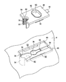
以下、添付図面を参照して、本発明に従う注射針廃棄用容器の一実施形態について説明する。図1において、注射針廃棄用容器2は、例えば使用済みの注射針や脱脂綿などの医療廃棄物を収容するための容器本体4を備えている。容器本体4は上面が開放された箱状であり、この容器本体4の上面開口6はプレート状の蓋体8によって覆われている。また、蓋体8の後側部には、蓋体8の上面を覆うためのカバー体10がヒンジ12を介して開閉自在に取り付けられている。カバー体10の先端部にはフック14が設けられ、また蓋体8には、このフック14に対応して受け凹部16が設けられ、このフック14が受け凹部16に着脱自在に受け入れられる。この蓋体8には、矩形状の投入用開口18が設けられており、例えば使用済みの脱脂綿などがこの投入用開口18を通して容器本体4内に投入される。
この注射針廃棄用容器2は、ねじ式タイプの注射器24(例えば、インシュリン用注射器)の注射針26を廃棄することができるように、次の通りに構成されている。図1とともに図2~図11を参照して、このねじ式タイプの注射器24は、注射器本体28を備え、この注射器本体28の先端部に注射針26が螺着されている(図1及び図10参照)。注射器本体28の先端部には小径突部30が設けられ、この小径突部30の先端部に針取付部32が設けられ、この針取付部32の外周面に雄ねじ部34が設けられている。注射針26は、円筒状の針保持部材36(所謂、ハブ)と、この針保持部材36に保持された針本体38とを有し、針保持部材36の端壁(図示せず)を貫通して針本体38が保持されている。この針保持部材36の内周面には、注射器本体28側の雄ねじ部34に対応して雌ねじ部(図示せず)が設けられている。このように構成されているので、注射針26の雌ねじ部を注射器本体28の雄ねじ部34に螺着することにより、注射器本体28に注射針26を取り付けて注射器24として使用することができ、またこの状態で注射針26を離脱方向に回動させることにより、注射器本体28から注射針26を取り外すことができる。
この実施形態では、注射針26の針保持部材36の外周面には、周方向に実質上等間隔をおいて複数(この形態では、図10に示すように16個)の係合凹部40が設けられ、これら複数の係合凹部40は、針保持部材36の軸線方向(図10及び図11において上下方向)に直線状に延びており、このように係合凹部40を設けることにより、隣接する係合凹部40間に縦リブが形成され、これら縦リブは針保持部材36の外周面に周方向に設けられる。
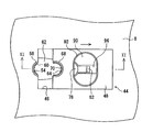
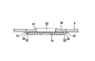
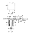
容器本体4側の蓋体8には装着部44が設けられ、この装着部44には矩形状の装着用凹部46が設けられている(図2参照)。装着用凹部46は蓋体8の上面に形成されており、この装着用凹部46にはプレート状の移動部材48が装着用凹部46に沿ってスライド移動自在に装着されている。移動部材48の両側部には、移動部材48のスライド移動方向(図3~図6、図10及び図11において左右方向、図7において紙面に対して垂直方向)に延びる一対の装着用爪部50が設けられている。また、装着用凹部46の両側部には、一対の装着用爪部50に対応して一対の装着用開口52が設けられ、これら装着用開口52が上記スライド移動方向に延びている。移動部材48側の一対の装着用爪部50が一対の装着用開口部52を通して装着用開口部52の縁部にスライド移動自在に係合されている(図7参照)。これら一対の装着用爪部50及び一対の装着用開口部52はスライド機構53(図7参照)を構成し、このスライド機構53を介して移動部材48が保持位置(図3、図5、図8及び図10に示す位置であって、後述する如く注射針26を保持する位置)と、この保持位置から後退する後退位置(図4、図6、及び図11に示す位置であって、注射針26の保持状態を解除する位置)との間を所定方向にスライド移動される。
この実施形態では、蓋体8の装着部44の一端部、具体的には装着用凹部46の一端部に、略半円筒状の第1保持部54が設けられ、この第1保持部54は、容器本体4内に向けて下方に延びている。第1保持部54の内周面(即ち、略半円弧状の凹状内面)における上端部には、第1保持凹部56が設けられ、この第1保持凹部56は、注射器本体28の小径突部30の先端部の外周形状に対応した形状を有し、後述する如く注射針26を挿入すると、注射器本体28の小径突部30の先端面がこの第1保持凹部56の底面58に当接する(図10参照)。
この第1保持部54の内周面の大部分には、周方向に間隔をおいて複数の係合突部60が設けられ、これら複数の係合突部60は、注射針26の針保持部材36の複数の係合凹部40の形状に対応した形状を有し(図8、図10及び図11参照)、第1保持部54の径方向内方に突出し、第1保持部54の上部から下端まで下方に延びている。これら複数の係合突部60が設けられた領域が保持領域として機能する。また、装着用凹部46の一端側(この形態では、第1保持部54側)に落下開口62が設けられ、この落下開口62は、装着用凹部46の一端部からその中央部付近まで放物線状に延びている。
また、移動部材48の一端部(即ち、第1保持部54側の端部)には略半円筒状の第2保持部64が設けられ、この第2保持部64は、落下開口62を通して容器本体4内に向けて下方に延びている。この第2保持部64の内周面(即ち、略半円弧状の凹状内面)の上側部には第2保持凹部66が設けられ、この第2保持凹部66は、注射器本体28の小径突部30の外周面の形状に対応した形状を有し、後述する如く注射針26を挿入すると、注射器本体28の小径突部30の先端面がこの第2保持凹部66の底面68に当接する(図10参照)。
この第2保持部64の内周面の大部分には、周方向に間隔をおいて複数の係合突部70が設けられ、この複数の係合突部70は、注射針26の針保持部材36の複数の係合凹部40の形状に対応した形状を有し(図8、図10及び図11参照)、第2保持部64の径方向内方に突出し、第2保持部64の上部から下端まで下方に延びている。これら複数の係合突部70が設けられた領域が保持領域として機能し、第1保持部54の複数の係合突部60と第2保持部64の複数の係合突部70との間の領域が係合突部が存在しない非保持領域となる。
この注射針廃棄用容器2では、移動部材48を保持位置に位置付けると、移動部材48の一端部が装着用凹部46の一端部に接触乃至近接し、蓋体8側の第1保持部54と移動部材48側の第2保持部64とは、相互に協働して円筒状の注射針保持部72を構成し、複数の係合突部60,70は、かかる注射針保持部72の内周面に間隔をおいて配置される係合突部を構成する(図3、図5、図8及び図10参照)。また、第1保持部54の第1保持凹部56と第2保持部64の第2保持凹部66とは、相互に協働して注射器本体28の小径突部30の先端部を着脱自在に受け入れる保持凹部を構成する。
また、この移動部材48を後退位置に位置付けると、移動部材48の他端部が装着用凹部46の他端部に接触乃至近接し、第2保持部64が第1保持部54から離隔して注射針保持部72が開放される(図4、図6、図9及び図11参照)。尚、第1及び第2保持部54,64については、後に詳述する。
この実施形態では、移動部材48を保持位置にロック保持するためのロック機構76が設けられている。このロック機構76は、移動部材48の下方において装着用凹部46の中央部に傾動自在に設けられた傾動部材78と、移動部材48の下面に設けられたロック用突部80とを備える。傾動部材78の先端部には、ロック用爪部82が上方に幾分突出して設けられ、このロック用爪部82の先端部には第1テーパ部86が形成されている。また、ロック用突部80の先端部には、ロック用爪部82の第1テーパ部84に対応して第2テーパ部84が形成されている。
また、傾動部材78の上面の一部には、その基端部側から先端部側に向けて上り傾斜となる傾斜面88が設けられている(図10及び図11参照)。また、移動部材48には楕円形状の操作用開口90が設けられ、この操作用開口90を通して傾動部材78の上面(傾斜面88)が外部に露出されている。操作用開口90の縁部には、リング状の操作用突部92が上方に幾分突出して設けられており、このように操作用突部92を設けることにより、操作用開口90をとおしての傾動部材78の傾斜面88の押圧操作が容易となる。
この傾動部材78は、ロック用爪部82がロック用突部80に係合するロック位置(図8において実線で示す)と、ロック用爪部82がロック用突部80から離脱するロック解除位置(図8において一点鎖線で示す)との間を上下方向に傾動自在である。この傾動部材78は、上記ロック位置と上記ロック解除位置との間を弾性変形可能であり、通常ロック位置に保持される。
この実施形態では、装着用凹部46に移動用開口94が設けられ、この移動用開口94は、ロック用突部80の移動経路に沿って延びている。移動部材48の他端部(第2保持部64とは反対側の端部)には目隠し部96が設けられ、この目隠し部96は、下方にL字状に延びている。移動部材48が上記保持位置に位置付けられた際に、この目隠し部96は、装着用凹部46の移動用開口94の一部を下方より覆う。また、移動部材48の下面において、操作用開口90と第2保持部64との間にはぬすみ部98が設けられている。このぬすみ部98は、移動部材48が上記後退位置に位置付けられた際に、後退位置に移動した移動部材48が傾動部材78の上面に干渉するのを防止する(図11参照)。
次に、主として図8及び図9を参照して、蓋体8側の第1保持部54及び移動部材48側の第2保持部64について説明する。この実施形態では、第1保持部54の開口端は、移動部材48が上記保持位置に位置するときに構成される注射針保持部72の中心P(図8参照)を通り且つ矢印100で示すスライド移動方向に対して実質上垂直な基準中心軸線Lを基準にして、蓋体8側の第1保持部54側にずれて位置しており、この開口端の基準中心軸線Lからのずれ量D(図8参照)は、注射針26の針保持部材36の外径をdとしたときに(0.1~0.4)dである(0.1d≦D≦0.4d)のが好ましく、(0.15~0.3)dであるのが更に望ましい。第1保持部54の開口端をこのように基準中心軸線Lに対して第1保持部54側にずらすことにより、移動部材48が上記後退位置に向けて移動したときに、蓋体8側の第1保持部54に保持された注射針26の半分を超える部分がこの第1保持部54から露出する。
一般的に、注射針26は中心を通る任意の径方向の軸線に対して対称に形成され、その重心は、注射針保持部72に挿入保持された状態ではこの注射針保持部72の中心Pに位置しており、従って、図8から理解されるように、移動部材48を上記後退位置に移動させたときに、注射針26の自重が蓋体8側の第1保持部54から離脱落下させる力として作用し、その自重を利用して注射針26を容器本体4内に落下収容させることができる。
第1保持部54のずれ量Dが過小であると、移動部材48を上記後退位置に移動させたときの第1保持部54からの注射針26の露出量が少なく、注射針26の自重による離脱落下力が小さくなり、注射針26の自重を利用した落下収容ができなくなるおそれがあり、またこのずれ量Dが過大であると、蓋体8側の第1保持部54の複数の係合突部60と注射針26の針保持部材36の複数の係合凹部40との係合状態が充分でなくなり、後述する注射器本体28の注射針26からの離脱ができなくなるおそれがある。
第1保持部54の開口端が基準中心軸線Lから第1保持部54側にずれていることに関連して、更に、次の通りに構成されている。即ち、移動部材48側の第2保持部64の開口端部102、104は、基準中心軸線Lよりも第1保持部54側に延び、それらの内面は第1保持部54側に向けて幾分径方向外方に拡がるように構成され、かかる開口端部102,104の内面には、注射針26側の針保持部材36の複数の係合凹部40に係合する係合突部が設けられておらず、かかる開口端部102,104の内面が非保持領域となっている。このように第2保持部64の開口端部102、104を径方向に拡がるように構成するとともに、かかる開口端部102,104の内面を平面状にする(換言すると、係合突部が存在しない非保持領域とする)ことにより、かかる開口端部102,104が第1保持部54に保持された注射針26の針保持部材36に作用することがなく、移動部材48の上記保持位置への移動及び上記後退位置への移動をスムースに行うことができる。尚、この第2保持部64の開口端部102,104の内面は、開口端に向けて径方向外方に拡がるようにしているが、このような構成に代えて、この開口端に向けて接線方向に直線状に、或いは凹部を設けて開口端に向けて直線状に延びるようにしてもよい(後述する図12及び図13参照)。
次に、上述した注射針廃棄用容器2を用いて、ねじ式タイプの注射器24の注射針26を廃棄する方法について説明する。まず、移動部材48を上記保持位置に位置付ける。かくすると、図10に示すように、傾動部材78のロック用爪部82が蓋体8側のロック用突部80に係合してロック機構76がロック状態となり、この移動部材48が上記保持位置にロック保持され、蓋体8側の第1保持部54と移動部材48側の第2保持部64とが注射針保持部72を構成する。
次いで、この状態において、使用済みの注射針26の針保持部材36を注射針保持部72内に挿入する(図10参照)。かく挿入すると、注射器本体28の小径突部30の先端部が注射針保持部72の保持凹部(第1保持部54の第1保持凹部56及び第2保持部64の第2保持凹部66)に当接し、注射針26が注射針保持部72に保持される。この保持状態においては、第1及び第2保持部54,64の複数の係合突部60,70が注射針保持部材36の外周面の複数の係合凹部40に係合した状態に保持される。
次に、注射針26を注射針保持部72に挿入した状態で、注射器本体28を注射針26に対して図10に矢印Rで示す離脱方向に回動する。かく回動すると、針保持部材36の雌ねじ部(図示せず)と注射器本体28の針取付部32の雄ねじ部34との螺合状態が解除され、注射器本体28が注射針26の針保持部材36から取り外される。このとき、移動部材48がロック機構76によって上記保持位置にロック保持されているので、注射器本体28を注射針26に対して相対的に回転させる際に、この移動部材48が上記後退位置にスライド移動することがない。
その後、使用者は指先を操作用開口90に挿入して傾動部材78の上面を下方に押圧し、傾動部材78を下方に傾動させてロック用爪部82と蓋体8側のロック用突部80との係合を解除し(即ち、ロック機構76のロック状態を解除する)、かくロック解除した状態でもって指先を操作用突部92に引っ掛けるなどして、移動部材48を上記保持位置から上記後退位置にスライド移動させる。かくスライド移動させると、図11に示すように、移動部材48側の第2保持部64が、蓋体8側の第1保持部54に保持された注射針26(即ち、針保持部材36)から離れ、この注射針26がその自重でもって移動部材48側に傾き、その針保持部材36が第1保持部54から離脱し、かく離脱した注射針26が落下開口62を通して容器本体4内に落下収容される。このように注射針26の自重を利用し、移動部材48を後退位置に移動させるという簡単な操作でもって、注射器本体28から外した注射針26を容器本体4内に収容することができる。
注射針26を容器本体4内に回収した後には、次の回収準備として、移動部材48を上記後退位置から上記保持位置にスライド移動させる。このとき、ロック用爪部82の第1テーパ部84がロック用突部80の第2テーパ部86上をスライド移動し、これによって、傾動部材78が下方に傾動されてロック用爪部82がロック用突部80に係合し、このようにしてロック機構76がロック状態となり、移動部材48が上記保持位置にロック保持される。
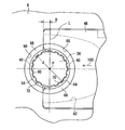
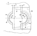
上述した実施形態では、移動部材48側の第2保持部64において、その底部から基準中心軸線Lまでの領域、即ち180度の角度範囲にわたって複数の係合突部70が設けられているが、これら係合突部70が径方向内方に突出しているために、それらの突出量が大きくなると、移動部材48を上記後退位置に向けて移動させた際に移動部材48に保持された状態で注射針26(針保持部材36)が後退位置に移動するおそれが生じる。従って、このような問題を解消するためには、図12及び図13に示すように構成するのが望ましい。尚、この変形形態において、図1~図11に示す実施形態と実質上同一の部材には同一の参照番号を付し、その説明を省略する。
図12及び図13において、この変形形態では、移動部材48Aの第2保持部64Aの底部から一端側の開口端部102A側に第1所定角度α1までの第1底部領域S1及びこの底部から他端側の開口端部104A側に第2所定角度α2までの第2底部領域S2の内面には、これら底部領域S1,S2にわたって複数の係合突部70が設けられて保持領域となり、これら複数の係合突部70が針保持部材36の他端側においてその係合凹部40に係合する。また、この第1所定角度α1からその一端側の開口端部102Aの開口端までの第1開口部領域K1及び第2所定角度α2からその他端側の開口端部104Aの開口端までの第2開口部領域K2の内面は平面状に形成されて非保持領域となり、これらの開口部領域K1,K2には、針保持部材36の係合凹部40に係合する係合突部が存在しない。
第1底部領域S1と第1開口部領域K1(非保持領域)との第1境界Q1となる第1所定角度α1は、30~70度であるのが好ましく、35~50度であるのがより好ましく、また第2底部領域S2と第2開口部領域K2(非保持領域)との第2境界Q2となる第2所定角度α2も、30~70度であるのが好ましく、35~50度であるのがより好ましい。
例えば、上述したように、外周面に周方向に等間隔をおいて16個の係合凹部40を有する針保持部材36を備えた注射針に適用する場合、移動部材48A側の第2保持部64Aにおける第1底部領域S1に二つの係合突部70(保持領域)が存在し、また第2底部領域S2に二つの係合突部70(保持領域)が存在するように構成することができる。
第1及び第2底部領域S1,S2を規定する第1及び第2所定角度α1,α2が過小になると、針保持部材36の係合凹部40に係合する係合突部70の個数が少なくなり、針保持部材36の複数の係合凹部40と第2保持部64Aの係合突部70との係合状態が充分でなくなるおそれがあり、また第1及び第2所定角度α1,α2が過大になると、第1保持部64Aの係合突部70(特に、開口端部側に位置する係合突部70)が針保持部材36の係合凹部40から離脱し難くなり、移動部材48Aを上記後退位置に向けて移動させた際に、この移動部材48Aとともに針保持部材36が後退位置に向けて移動するおそれがある。
この変形形態のその他の構成(例えば、蓋体8側の第1保持部54などの構成)は、上述した構成と実質上同一でよい。このような変形形態では、移動部材48Aの第2保持部64Aの第1及び第2開口部領域K1,K2が係合突部が存在しない非保持領域となっているので、第2保持部64Aの第1及び第2開口部領域K1,K2の内面が注射針保持部72Aに保持された針保持部材36に作用することがなく、これによって、移動部材48Aを図12に示す保持位置から図13に示す後退位置に移動させても、この移動部材48Aとともに針保持部材36(即ち、注射針)が移動することがなく、その結果、上述したように、蓋体8側に残る注射針(針保持部材36)をその自重を利用して容器本体内に確実に落下収容することができる。
例えば、上述した実施形態では、第1所定角度α1と第2所定角度α2とを同一の角度に設定しているが、必ずしも同一の角度に設定する必要はなく、第1所定角度α1を第2所定角度α2よりも大きく(又は小さく)設定するようにしてもよい。
以上、本発明に従う注射針廃棄用容器の一実施形態及びその変形形態について説明したが、本発明はかかる実施形態及び変形形態に限定されるものではなく、本発明の範囲を逸脱することなく種々の変形乃至修正が可能である。
例えば、上述した実施形態では、注射針26の針保持部材36の外周面に複数の係合凹部40を設けるとともに、蓋体8側の第1保持部54及び移動部材48側の第2保持部64の内周面に複数の係合突部60,70を設けているが、このような構成とは反対に、注射針26の針保持部材36側に複数の係合突部を設けるとともに、第1及び第2保持部54,64側に複数の係合凹部を設けるようにしてもよい。
上述した注射針廃棄用容器の効果は、下記の通りである。この注射針廃棄用容器では、移動部材はスライド機構を介して保持位置と後退位置の間をスライド自在に装着され、この移動部材を保持位置に位置付けると、蓋体側の第1保持部と移動部材側の第2保持部とが、注射針の針保持部材を保持するための注射針保持部を構成する。注射器の注射針を廃棄する際には、移動部材が保持位置に位置付けられ、注射針の針保持部材が,第1及び第2保持部により構成される注射針保持部に挿入保持され、蓋体側の第1保持部が注射針の片側を、移動部材側の第2保持部がこの注射針の他側を保持する。この挿入保持状態において、注射器本体を離脱方向に回転させると、容器本体側の注射針保持部に保持された針保持部材から注射器本体が取り外される。その後、移動部材を後退位置に位置付けると、移動部材の第2保持部が注射針の針保持部材から離れて保持状態が解除され、これにより、注射針が落下開口を通して容器本体内に落下収容される。
また、蓋体側の第1保持部の開口端は、保持位置状態の注射針保持部の基準中心軸線を基準にして、第1保持部側にずれて位置しているので、移動部材を後退位置まで移動させると、蓋体側の第1保持部から注射針の針保持部材の半分を超える部分が外部に露出され、注射針の重心は蓋体側の第1保持部の外側に位置するようになる。従って、蓋体側の第1保持部に保持された針保持部材の自重が離脱落下させる力として作用しやすく、これによって、注射器本体から外れた注射針を容器本体内に落下収容することができる。
また、蓋体側の第1保持部の開口端の基準中心軸線からのずれ量Dは、注射針の針保持部材の外径をdとしたときに(0.1~0.4)dであるので、移動部材を後退位置まで移動させると、この第1保持部に保持された注射針の重心は、この第1保持部の開口端より外側に(0.1~0.4)dの距離だけ離れた位置となり、従って、かかる距離に起因して第1保持部に保持された針保持部材の自重が離脱落下させる力として作用し、これによって、注射器本体から外れた注射針を容器本体内に落下収容することができる。
また、注射針の針保持部材の外周面には、周方向に間隔をおいて複数の係合凹部(又は係合突部)が設けられ、蓋体側の第1保持部及び移動部材側の第2保持部の内周面には、周方向に間隔おいて複数の係合突部(又は係合凹部)が設けられているので、針保持部材側の複数の係合凹部(又は係合突部)を容器本体側の第1及び第2保持部の複数の係合突部(又は係合凹部)に係止保持することができる。
また、注射針の針保持部材の外周面には複数の係合凹部が設けられ、蓋体側の第1保持部及び移動部材側の第2保持部の内周面には複数の係合突部が設けられているので、このような形態の注射針の廃棄に好適な廃棄用容器として提供することができる。また、移動部材側の第2保持部における基準中心軸線から第1保持部側に突出する開口端部は、蓋体側の第1保持部側に向けて直線状に(又は径方向外方に拡がるように)延び、この第2保持部の開口端部の内面には係合突部が存在していないので、この第2保持部の開口端部が注射針の針保持部材の外周面に作用することがなく、移動部材を後退位置に移動させた際に、注射器本体から外れた注射針が容器本体内にスムースに落下収容される。
また、移動部材側の第2保持部においては、この第2保持部の第1底部領域及び第2底部領域にわたって複数の係合突部が設けられ、その第1開口部領域及び第2開口部領域には係合突部が存在しないので、保持位置に保持された状態においては、第1及び第2底部領域の複数の係合突部が注射針の針保持部材の複数の係合凹部に係合して確実に保持し、また後退位置に移動させたときには、第2保持部側の複数の係合突部が蓋体側の第1保持部に保持された注射針の針保持部材の外周面に作用することがなく、移動部材を後退位置に移動させた際に第2保持部に保持されて注射針が後退位置に移動するのを防止することができる。
また、第1底部領域と第1開口部領域との第1境界となる第1所定角度は30~70度であり、また第2底部領域と第2開口部領域との第2境界となる第2所定角度は30~70度であるので、移動部材を後退位置に移動させたときには、第2保持部側の複数の係合突部が蓋体側の第1保持部に保持された注射針の針保持部材の外周面に作用することがなく、移動部材を後退位置に移動させた際に第2保持部に保持されて注射針が後退位置に移動されるのを確実に防止することができる。
また、ロック機構が蓋体側の傾動部材と移動部材側のロック用突部とから構成され、傾動部材の先端部にロック用爪部が設けられているので、傾動部材のロック用爪部が移動部材のロック用突部に係合することによって、移動部材を保持位置にロック保持することができる。また、操作用開口部を通して傾動部材の上面が外部に露出されているので、指先などを操作用開口部に挿入し、この指先などで傾動部材の上面を押圧してこのロック状態を解除することができ、加えて、このロック解除位置に傾動させる操作と、指先などを操作用開口部に引っ掛けて移動部材を後退位置にスライド移動させる操作とを一動作で行うことができる。
また、前記移動部材側の前記第2保持部の内周面には注射針と係合する保持領域と注射針と係合しない非保持領域が設けられている。このため、移動部材の後退位置へのスライド後、注射針が第2保持部に残留してしまう可能性を低減させることができる。
また、非保持領域は前記移動部材側の前記第2保持部における前記基準中心軸線から前記第1保持部側に突出する部分に設けられている。すなわち、非保持領域が第2保持部における開口側に設けられている。このため、移動部材の後退位置へのスライド後、注射針が第2保持部から離れやすく、廃棄容器内に落下収容させやすい。
また、前記保持領域は注射針と係合する係合突部であり、前記係合突部は、注射針外周面に形成された縦リブと係合する高さを備え、且つ、前記移動部材のスライド時に注射針外周面の縦リブに対してスライド方向の力が加わらないように形状付けられている。このため、移動部材のスライド時に、注射針が移動部材側に保持されたままスライドする事態がなく、確実に注射針を廃棄容器本体内に落下収容させることができる。
本発明の応用変形例としては、前記移動部材の第2保持部及び蓋体側の第1保持部は、注射針と係合する保持領域を有し、前記移動部材の第2保持部及び/又は蓋体側の第1保持部は、注射針と係合しない非保持領域とを有し、非保持領域は保持部における開口端部側に設けられており、前記保持領域は注射針と係合する係合突部であり、前記係合突部は、注射針外周面に形成された縦リブと係合する高さを備え、且つ、前記移動部材のスライド時に注射針外周面の縦リブに対してスライド方向の力が加わらないように形状付けられている形態が考えられる。この場合、前記蓋体側の第1保持部及び前記移動部材側の第2保持部における保持領域は、前記移動部材のスライド移動時に注射針に対してスライド移動方向に力が加わらない。つまり、前記移動部材のスライド移動時において、保持部は注射針を保持不可能に形成されている。よって、前記移動部材のスライド移動時に伴い、自然に注射針は廃棄容器内に落下収容される。なお、本形態においては、前記蓋体側の前記第1保持部の開口端は、前記保持位置状態の前記注射針保持部の中心を通り且つ前記移動部材のスライド移動方向に対して実質上垂直な基準中心軸線に対して、前記第1保持部側にずれて位置していなくともよい。
この変形形態では、移動部材の上記後退位置に向けての移動の際に注射針の縦リブにスライド方向の力が作用しないように、例えば、図14に示すように構成される。即ち、第2保持部64Bの非保持領域K1,K2の開口側部74,76は、開口端に向けて内径が漸増するように構成され、これによって第2保持部64Bの開口側部74,76は、開口端側に向けて半円形状よりも幾分拡がるように形成されている。このように構成することによって、移動部材48Bが上記後退位置に向けて移動する際に、この第2保持部38Bの内周面が注射針24の縦リブに作用することがなく、この縦リブに移動部材48Bからの力が作用するのを回避することができる。
加えて、第2保持部64Bに設けられた各係合突部70Bは、その両側面80,82が先端(即ち、径方向内方)に向けて内側に傾斜し、各係合突部70Bの横断面形状が台形状に形成されている。このように構成することによって、移動部材48Bが上記後退位置に向けて移動する際に、第2保持部64Bの複数の係合突部70Bが注射針24の縦リブに作用することがなく、係合突部70Bを介した移動部材48Bからの力が注射針24の縦リブに作用するのを回避することができる。このため、移動部材48Bを上記後退位置に向けて移動した際に、注射針24の針保持部材36が移動部材48Bに持ってかれることがない。尚、各係合突部70Bの側面80,82のこのような傾斜は、その両側面に設ける必要はなく、その片側(即ち、開口端部102A,104A側とは逆の側面82)に設けることによって所望の効果を達成することができる。
このように、非保持領域を第1保持部及び/或いは第2保持部に設けることにより、所定保持部に注射針が残留しないようにすることができ、このため、注射針を注射器本体から取り外して容器本体内に落下収容させやすい注射針廃棄用容器を実現することができる。
以上が図を基にした実施形態であるが、本発明は当該実施形態のみに限られることはない。例えば、実施形態では、装着部の一端に第1保持部が形成されるとともに、移動部材の一端に第2保持部が形成されているが、装着部にスライド自在な二つの移動部材を有し、当該二つの移動部材のそれぞれに第1保持部と第2保持部を形成してもよく、つまりは、複数の移動部材により注射針保持部が形成されていてもよい。
2 注射針廃棄用容器
4 容器本体
8 蓋体
26 注射針
28 注射器本体
36 針保持部材
40 係合凹部
44 装着部
48,48A,48B 移動部材
50 装着用爪部
52 装着用開口
54 第1保持部
60,70 係合突部
62 落下開口
64,64A,64B 第2保持部
72 注射針保持部
76 ロック機構
4 容器本体
8 蓋体
26 注射針
28 注射器本体
36 針保持部材
40 係合凹部
44 装着部
48,48A,48B 移動部材
50 装着用爪部
52 装着用開口
54 第1保持部
60,70 係合突部
62 落下開口
64,64A,64B 第2保持部
72 注射針保持部
76 ロック機構
Claims (8)
- 注射器本体の先端部に着脱自在に螺着される針保持部材及び前記針保持部材に保持された針本体を有する注射針を廃棄するための注射針廃棄用容器であって、
廃棄物を収容するための容器本体と、前記容器本体の開口部を覆う蓋体と、前記蓋体に設けられた装着部にスライド機構を介して所定方向にスライド移動自在に装着された移動部材と、を備え、前記装着部の一端部には、前記注射針の前記針保持部材の片側を保持するための第1保持部が設けられているとともに、前記第1保持部に関連して落下開口が設けられ、また前記移動部材には、前記注射針の前記針保持部材の他側を保持するための第2保持部が設けられており、
前記移動部材を前記所定方向に保持位置まで移動させると、前記移動部材が前記第1保持部に近接する方向に移動し、前記蓋体側の前記第1保持部と前記移動部材側の前記第2保持部とは、相互に協働して前記注射針を保持するための注射針保持部を構成し、前記移動部材が前記第1保持部から離れる方向に移動させると、前記注射針保持部が開放されて前記装着部の前記落下開口を通しての前記注射針の落下が許容されるように構成されており、
更に、前記蓋体側の前記第1保持部の開口端は、前記保持位置状態の前記注射針保持部の中心を通り且つ前記移動部材のスライド移動方向に対して実質上垂直な基準中心軸線に対して、前記第1保持部側にずれて位置していることを特徴とする注射針廃棄用容器。 - 前記蓋体側の前記第1保持部の前記開口端の前記基準中心軸線からのずれ量Dは、前記注射針の前記針保持部材の外径をdとしたときに(0.1~0.4)dである(0.1d≦D≦0.4d)ことを特徴とする請求項1に記載の注射針廃棄用容器。
- 前記移動部材側の前記第2保持部の内周面には前記注射針と係合する保持領域と前記注射針と係合しない非保持領域が設けられていることを特徴とする請求項2に記載の注射針廃棄用容器。
- 前記非保持領域は前記移動部材側の前記第2保持部における前記基準中心軸線から前記第1保持部側に突出する開口端部に設けられていることを特徴とする請求項3に記載の注射針廃棄用容器。
- 前記保持領域は前記注射針と係合する係合突部であり、前記係合突部は、前記注射針の外周面に形成された縦リブと係合する高さを備え、且つ、前記移動部材のスライド時に前記注射針の外周面の前記縦リブに対してスライド方向の力が加わらないように形状付けられている請求項4に記載の注射針廃棄用容器。
- 注射器本体の先端部に着脱自在に螺着される針保持部材及び前記針保持部材に保持された針本体を有する注射針を廃棄するための注射針廃棄用容器であって、
廃棄物を収容するための容器本体と、前記容器本体の開口部を覆う蓋体とを備え、
前記蓋体が、前記注射針の前記針保持部材の片側を保持する第1保持部と、前記第1保持部から離れる方向にスライド移動自在に設けられて、前記注射針の前記針保持部材の他側を保持するとともに、前記第1保持部から離れる方向にスライド移動させることにより、前記第1保持部との間に針落下開口を形成する第2保持部とを有し、
前記第2保持部を前記所定方向に保持位置まで移動させると、前記第二保持部が前記第1保持部に近接する方向に移動し、前記第1保持部と前記第2保持部とは、相互に協働して前記注射針を保持するための注射針保持部を構成し、前記第2保持部が前記第1保持部から離れる方向に移動させると、前記注射針保持部が開放されて前記落下開口を通しての前記注射針の落下が許容されるように構成されており、
更に、前記第2保持部及び前記第1保持部は、前記注射針と係合する保持領域を有するとともに、
前記移動部材の前記第2保持部及び/又は前記蓋体側の前記第1保持部は、前記注射針と係合しない非保持領域を有することを特徴とする注射針廃棄用容器。 - 前記保持領域は前記注射針と係合する係合突部であり、前記係合突部は、前記注射針の外周面に形成された縦リブと係合する高さを備え、且つ、前記移動部材のスライド時に前記注射針の外周面の前記縦リブに対してスライド方向の力が加わらないように形状付けられていることを特徴とする請求項6に記載の注射針廃棄用容器。
- 注射器本体の先端部に着脱自在に螺着される針保持部材及び前記針保持部材に保持された針本体を有する注射針を廃棄するための注射針廃棄用容器であって、
廃棄物を収容するための容器本体と、前記容器本体の開口部を覆う蓋体とを備え、
前記蓋体が、前記注射針の前記針保持部材の片側を保持する第1保持部と、前記第1保持部から離れる方向にスライド移動自在に設けられて、前記注射針の前記針保持部材の他側を保持するとともに、前記第1保持部から離れる方向にスライド移動させることにより、前記第1保持部との間に針落下開口を形成する第2保持部とを有し、
前記第2保持部を前記所定方向に保持位置まで移動させると、前記第二保持部が前記第1保持部に近接する方向に移動し、前記第1保持部と前記第2保持部とは、相互に協働して前記注射針を保持するための注射針保持部を構成し、前記第2保持部が前記第1保持部から離れる方向に移動させると、前記注射針保持部が開放されて前記落下開口を通しての前記注射針の落下が許容されるように構成されており、
更に、前記第1保持部の開口端は、前記保持位置状態の前記注射針保持部の中心を通り且つ前記第2保持部のスライド移動方向に対して実質上垂直な基準中心軸線に対して、前記第1保持部側にずれて位置していることを特徴とする注射針廃棄用容器。
Priority Applications (3)
| Application Number | Priority Date | Filing Date | Title |
|---|---|---|---|
| US15/328,421 US10080621B2 (en) | 2014-07-31 | 2015-07-28 | Syringe needle disposal container |
| SG11201700591XA SG11201700591XA (en) | 2014-07-31 | 2015-07-28 | Syringe needle disposal container |
| DE112015003511.7T DE112015003511T5 (de) | 2014-07-31 | 2015-07-28 | Kanülenabwurfbehälter |
Applications Claiming Priority (2)
| Application Number | Priority Date | Filing Date | Title |
|---|---|---|---|
| JP2014156526A JP6346025B2 (ja) | 2014-07-31 | 2014-07-31 | 注射針廃棄用容器 |
| JP2014-156526 | 2014-07-31 |
Publications (1)
| Publication Number | Publication Date |
|---|---|
| WO2016017609A1 true WO2016017609A1 (ja) | 2016-02-04 |
Family
ID=55217509
Family Applications (1)
| Application Number | Title | Priority Date | Filing Date |
|---|---|---|---|
| PCT/JP2015/071308 Ceased WO2016017609A1 (ja) | 2014-07-31 | 2015-07-28 | 注射針廃棄用容器 |
Country Status (5)
| Country | Link |
|---|---|
| US (1) | US10080621B2 (ja) |
| JP (1) | JP6346025B2 (ja) |
| DE (1) | DE112015003511T5 (ja) |
| SG (1) | SG11201700591XA (ja) |
| WO (1) | WO2016017609A1 (ja) |
Families Citing this family (10)
| Publication number | Priority date | Publication date | Assignee | Title |
|---|---|---|---|---|
| JP7129050B2 (ja) * | 2017-06-13 | 2022-09-01 | ニプロ株式会社 | 針廃棄用容器 |
| WO2018230607A1 (ja) * | 2017-06-13 | 2018-12-20 | ニプロ株式会社 | 針廃棄用容器 |
| USD854310S1 (en) * | 2017-11-24 | 2019-07-23 | Siemens Healthcare Gmbh | Medical equipment container |
| WO2019133392A1 (en) * | 2017-12-28 | 2019-07-04 | Becton, Dickinson And Company | Pen needle assembly apparatus |
| KR102143485B1 (ko) * | 2018-05-17 | 2020-08-11 | 주식회사 뮨 | 주사기 절단 및 분리 배출 장치 |
| KR102143483B1 (ko) * | 2018-05-17 | 2020-08-11 | 주식회사 뮨 | 주사기 절단 및 분리 배출 장치 |
| US11471238B2 (en) * | 2018-12-10 | 2022-10-18 | Wake Forest University Health Sciences | Medical waste container |
| CN110787342A (zh) * | 2019-11-28 | 2020-02-14 | 上海市嘉定区南翔医院 | 一种在移动护理车上使用的利器盒 |
| US20240165345A1 (en) * | 2021-03-24 | 2024-05-23 | Decap Research And Development Incorporated | Receptacle for single-handedly uncapping, recapping and disposing a syringe's cap and needle |
| US12318231B2 (en) | 2023-09-13 | 2025-06-03 | Nitta Mold Corporation | Needle disposal container |
Citations (4)
| Publication number | Priority date | Publication date | Assignee | Title |
|---|---|---|---|---|
| JPS6420860A (en) * | 1987-07-16 | 1989-01-24 | Nissho Kk | Box for disposing used syringes |
| JPH021161U (ja) * | 1988-02-04 | 1990-01-08 | ||
| JPH1043256A (ja) * | 1996-07-31 | 1998-02-17 | Nissho Corp | 採血針廃棄容器 |
| WO2010122683A1 (ja) * | 2009-04-24 | 2010-10-28 | 株式会社ファインプロ | 注射針廃棄用容器 |
Family Cites Families (11)
| Publication number | Priority date | Publication date | Assignee | Title |
|---|---|---|---|---|
| US4738362A (en) * | 1987-09-21 | 1988-04-19 | Beral Enterprises | Device for removal and disposal of syringe needles |
| US4862573A (en) * | 1987-10-13 | 1989-09-05 | Kelson Lance P | Medical sampling needle removal and disposal device |
| US5300028A (en) * | 1991-04-15 | 1994-04-05 | Welcheck Jack S | Method and apparatus for preventing improper use and disposal of hypodermic needles |
| US5323900A (en) * | 1992-11-16 | 1994-06-28 | Hawk Tool & Mold Inc. | Apparatus for storing used medical needles |
| IT1265322B1 (it) * | 1993-01-29 | 1996-10-31 | Claudio Latini | Dispositivo per prevenire punture accidentali. |
| IN189561B (ja) * | 1996-06-21 | 2003-03-29 | Bio Plexus Inc | |
| JPH10127709A (ja) * | 1996-10-25 | 1998-05-19 | Dental Act:Kk | 注射針脱離処分装置 |
| US5947950A (en) * | 1998-02-19 | 1999-09-07 | Med-Safe Systems, Inc. | Gear driven needle removal device |
| US6253916B1 (en) * | 2000-04-27 | 2001-07-03 | Christopher R. Bickel | Sharps disposal assembly having improved unwinder |
| JP5161622B2 (ja) * | 2008-03-19 | 2013-03-13 | テルモ株式会社 | 注射針取外し装置 |
| US8875882B1 (en) * | 2013-04-16 | 2014-11-04 | Maan G. Salloum | Holder and disposal device for hypodermic needles |
-
2014
- 2014-07-31 JP JP2014156526A patent/JP6346025B2/ja active Active
-
2015
- 2015-07-28 SG SG11201700591XA patent/SG11201700591XA/en unknown
- 2015-07-28 WO PCT/JP2015/071308 patent/WO2016017609A1/ja not_active Ceased
- 2015-07-28 DE DE112015003511.7T patent/DE112015003511T5/de active Pending
- 2015-07-28 US US15/328,421 patent/US10080621B2/en active Active
Patent Citations (4)
| Publication number | Priority date | Publication date | Assignee | Title |
|---|---|---|---|---|
| JPS6420860A (en) * | 1987-07-16 | 1989-01-24 | Nissho Kk | Box for disposing used syringes |
| JPH021161U (ja) * | 1988-02-04 | 1990-01-08 | ||
| JPH1043256A (ja) * | 1996-07-31 | 1998-02-17 | Nissho Corp | 採血針廃棄容器 |
| WO2010122683A1 (ja) * | 2009-04-24 | 2010-10-28 | 株式会社ファインプロ | 注射針廃棄用容器 |
Also Published As
| Publication number | Publication date |
|---|---|
| JP2016032557A (ja) | 2016-03-10 |
| US20170209230A1 (en) | 2017-07-27 |
| US10080621B2 (en) | 2018-09-25 |
| DE112015003511T5 (de) | 2017-06-14 |
| JP6346025B2 (ja) | 2018-06-20 |
| SG11201700591XA (en) | 2017-02-27 |
Similar Documents
| Publication | Publication Date | Title |
|---|---|---|
| JP6346025B2 (ja) | 注射針廃棄用容器 | |
| JP2016032557A5 (ja) | ||
| JP5543152B2 (ja) | 医療廃棄物容器のヒンジ締結蓋 | |
| JP4822599B2 (ja) | 医療用安全処理キャップアセンブリ | |
| US4850976A (en) | Combination sheath and foldable shield for hypodermic syringe needle | |
| JP6379421B2 (ja) | 眼内レンズ用インジェクタ | |
| US5590782A (en) | Vial holder assembly | |
| EP1149599B1 (en) | Sharps disposal assembly having improved unwinder | |
| US20030038046A1 (en) | Apparatus and method for unwinding a needle portion | |
| CN103945787B (zh) | 医疗废弃物容器及其盖 | |
| JPH1043256A (ja) | 採血針廃棄容器 | |
| JPH05154134A (ja) | 血液採集装置 | |
| US9498111B2 (en) | Otoscope with ejectable ear speculum | |
| JP2001029334A (ja) | 圧迫解放式針ガード付注射器 | |
| JP5444332B2 (ja) | 注射針廃棄用容器 | |
| JPS62112531A (ja) | 採血針処理具用のキャップ | |
| JP2019189327A (ja) | 詰め替えセット及び容器 | |
| JP6215499B1 (ja) | 注射針用廃棄箱 | |
| KR20060113087A (ko) | 의료용 감염성 폐기물 수거용기 | |
| EP1350528A1 (en) | Needle-disposable insert for sharps disposal | |
| JP3115180U (ja) | 注射針取り外し器 | |
| US20100122925A1 (en) | Syringe disposal unit | |
| JP2022105107A (ja) | 針廃棄用容器 | |
| JP7222506B2 (ja) | ローラケース | |
| JP7129050B2 (ja) | 針廃棄用容器 |
Legal Events
| Date | Code | Title | Description |
|---|---|---|---|
| 121 | Ep: the epo has been informed by wipo that ep was designated in this application |
Ref document number: 15826710 Country of ref document: EP Kind code of ref document: A1 |
|
| WWE | Wipo information: entry into national phase |
Ref document number: 15328421 Country of ref document: US |
|
| WWE | Wipo information: entry into national phase |
Ref document number: 112015003511 Country of ref document: DE |
|
| 122 | Ep: pct application non-entry in european phase |
Ref document number: 15826710 Country of ref document: EP Kind code of ref document: A1 |