WO2016017575A1 - ピストンおよび緩衝器 - Google Patents
ピストンおよび緩衝器 Download PDFInfo
- Publication number
- WO2016017575A1 WO2016017575A1 PCT/JP2015/071232 JP2015071232W WO2016017575A1 WO 2016017575 A1 WO2016017575 A1 WO 2016017575A1 JP 2015071232 W JP2015071232 W JP 2015071232W WO 2016017575 A1 WO2016017575 A1 WO 2016017575A1
- Authority
- WO
- WIPO (PCT)
- Prior art keywords
- piston
- shock absorber
- seat
- diameter
- cylinder
- Prior art date
- Legal status (The legal status is an assumption and is not a legal conclusion. Google has not performed a legal analysis and makes no representation as to the accuracy of the status listed.)
- Ceased
Links
Images



Classifications
-
- F—MECHANICAL ENGINEERING; LIGHTING; HEATING; WEAPONS; BLASTING
- F16—ENGINEERING ELEMENTS AND UNITS; GENERAL MEASURES FOR PRODUCING AND MAINTAINING EFFECTIVE FUNCTIONING OF MACHINES OR INSTALLATIONS; THERMAL INSULATION IN GENERAL
- F16F—SPRINGS; SHOCK-ABSORBERS; MEANS FOR DAMPING VIBRATION
- F16F9/00—Springs, vibration-dampers, shock-absorbers, or similarly-constructed movement-dampers using a fluid or the equivalent as damping medium
- F16F9/32—Details
-
- F—MECHANICAL ENGINEERING; LIGHTING; HEATING; WEAPONS; BLASTING
- F16—ENGINEERING ELEMENTS AND UNITS; GENERAL MEASURES FOR PRODUCING AND MAINTAINING EFFECTIVE FUNCTIONING OF MACHINES OR INSTALLATIONS; THERMAL INSULATION IN GENERAL
- F16J—PISTONS; CYLINDERS; SEALINGS
- F16J1/00—Pistons; Trunk pistons; Plungers
-
- F—MECHANICAL ENGINEERING; LIGHTING; HEATING; WEAPONS; BLASTING
- F16—ENGINEERING ELEMENTS AND UNITS; GENERAL MEASURES FOR PRODUCING AND MAINTAINING EFFECTIVE FUNCTIONING OF MACHINES OR INSTALLATIONS; THERMAL INSULATION IN GENERAL
- F16J—PISTONS; CYLINDERS; SEALINGS
- F16J9/00—Piston-rings, e.g. non-metallic piston-rings, seats therefor; Ring sealings of similar construction
Definitions
- the present invention relates to improvements in pistons and shock absorbers.
- a piston As a piston, for example, it is slidably inserted into a cylinder of a shock absorber and divides the inside of the cylinder into two pressure chambers. Some have a pressure side port through which hydraulic fluid passes. Leaf valves are stacked above and below such a piston, and the outlet ends of the extension side port and the pressure side port are opened and closed by the leaf valve. During expansion and contraction of the shock absorber, resistance is given to the flow of hydraulic oil passing through the expansion side port and the compression side port by the leaf valve. Thereby, a difference arises in the pressure in the above-mentioned two pressure chambers, and a damping force is generated.
- ⁇ A synthetic resin piston ring that slides on the inner periphery of the cylinder is mounted on the outer periphery of such a piston.
- the extension side chamber and the pressure side chamber formed in the cylinder do not communicate with each other via the outer periphery of the piston, and the piston can move smoothly in the cylinder.
- the piston ring is mounted on a mounting portion having a plurality of protrusions arranged in the axial direction on the outer periphery of the piston, and is integrated with the piston.
- the piston ring has a disk shape before being attached to the piston, and is provided with a hole having a smaller diameter than the outer diameter of the piston at the center.
- a piston ring is laminated
- the shavings may bite into the valve and cause poor performance.
- the removal work is complicated, which causes a new problem of increased manufacturing costs.
- An object of the present invention is to provide a piston capable of suppressing generation of shavings when a piston ring is mounted and a shock absorber provided with the piston.
- the piston includes a disc-shaped piston body, and a cylindrical piston ring made of synthetic resin and attached to the outer periphery of the piston body.
- a disk portion having a mounting portion on the outer periphery to which the piston ring is mounted, a small diameter portion rising from one axial end side of the disk portion and having a smaller diameter than the disk portion, and an anti-disk portion side of the small diameter portion
- a seat portion having a larger diameter than the small-diameter portion and having an annular valve seat at the end of the small-diameter portion, and a first port that opens to the end of the counter-small-diameter portion of the disk portion and communicates with the inside of the valve seat
- a second port that opens at the end of the disk portion on the side opposite to the small-diameter portion and communicates between the sheet portion and the disk portion, and the sheet portion has an outer peripheral edge on the end on the side of the small-diameter portion Has a chamfer.
- FIG. 1 is a longitudinal sectional view of a shock absorber according to an embodiment of the present invention.
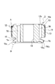
- FIG. 2A is an enlarged longitudinal sectional view of a piston in the shock absorber according to the embodiment of the present invention.
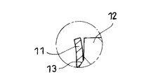
- 2B is an enlarged view of a portion A in FIG. 2A.
- FIG. 2C is an enlarged view of a portion B in FIG. 2A.
- FIG. 3 is a diagram illustrating a processing procedure for mounting a piston ring on a piston body in the shock absorber according to the embodiment of the present invention.
- FIG. 4 is a diagram illustrating a deformed state of the piston ring in the process of mounting the piston ring on the piston body of the shock absorber according to the embodiment of the present invention.
- FIG. 5A is a longitudinal sectional view of a piston in a shock absorber according to a comparative example of the present invention.
- FIG. 5B is an enlarged view of a portion C in FIG. 5A.
- shock absorber S according to the embodiment of the present invention will be described with reference to the drawings.
- the damping force rises quickly and the piston speed is high.
- a saturation characteristic in which the rate of increase of the damping force with respect to the piston speed becomes small may be preferred.
- such saturation characteristics may be preferred for the damping force characteristics on the extension side.
- the shock absorber can firmly suppress the vibration of the vehicle body when the piston speed is in the low speed range, and excessive damping force when the piston speed is in the high speed range. There is nothing. Thereby, the riding comfort in the vehicle can be improved.
- an annular leaf valve whose inner periphery is fixed is stacked on the piston, and the extension port is opened and closed with the leaf valve.
- a damping force is exerted by giving resistance to the flow of hydraulic oil passing through the expansion side port by a leaf valve.
- it is required to increase the pressure receiving area of the leaf valve as much as possible and to increase the diameter of the valve seat on which the leaf valve is seated.
- a large force can be applied to the leaf valve with a small pressure by increasing the pressure receiving area of the leaf valve.
- the valve seat diameter By increasing the valve seat diameter, the length from the inner peripheral support portion of the leaf valve to the valve seat is increased, and the bending rigidity of the leaf valve can be reduced. By doing so, the leaf valve is easily bent and a gap formed between the valve seat and the leaf valve is increased when the leaf valve is separated from the valve seat. Therefore, the resistance that the leaf valve gives to the flow of hydraulic oil when the piston speed is in the high speed range can be reduced, and the above-described saturation characteristic can be realized.
- the shock absorber S according to the present embodiment is a shock absorber that realizes such saturation characteristics.
- the configuration of the shock absorber S will be specifically described.
- the shock absorber S includes a cylinder 1, a piston 2 that is slidably inserted into the cylinder 1 and divides the cylinder 1 into an extension side chamber R ⁇ b> 1 and a pressure side chamber R ⁇ b> 2, and one end is a piston 2. And a piston rod 3 whose other end protrudes out of the cylinder 1.
- the shock absorber S is provided with a sliding partition wall 7 that slidably contacts the inner periphery of the cylinder 1 and divides the pressure side chamber R2 and the gas chamber G in the lower part of the cylinder 1 in the figure.
- the extension side chamber R1 and the compression side chamber R2 are filled with a liquid such as hydraulic oil.
- a liquid such as water or an aqueous solution can be used as the liquid filled in the extension side chamber R1 and the compression side chamber R2.
- the gas chamber G is filled with an inert gas such as nitrogen, but can be filled with a gas other than the inert gas.
- the lower end of the cylinder 1 in FIG. An annular rod guide 5 that slidably supports the piston rod 3 is mounted on the upper end of the cylinder 1 in FIG. Further, a seal member 6 that is in sliding contact with the outer periphery of the piston rod 3 is mounted on the upper end of the cylinder 1 in FIG. The seal member 6 seals the outer periphery of the piston rod 3 to prevent the liquid in the cylinder 1 from leaking.
- the piston 2 includes a disk-shaped piston main body 10 and a cylindrical piston ring 11 made of synthetic resin and attached to the outer periphery of the piston main body 10.
- the piston main body 10 includes a disk portion 12 having a mounting portion 13 to which the piston ring 11 is mounted on the outer periphery, and one end side in the axial direction of the disk portion 12 (the lower side in FIG. 1). 1 is formed on the lower side in FIG. 1 on the side opposite to the disk portion of the small diameter portion 14 and is formed to have a larger diameter than the small diameter portion 14, and becomes the end of the small diameter portion.
- a seat portion 15 having an annular valve seat 15 a at the lower end in FIG. 1, and an opening at the upper end in FIG.
- the second port 18 leading to the Includes an insertion hole 19 in which the piston rod 3 is inserted, the through small diameter portion 14, and the center of the seat portion 15 in the axial direction.
- the piston body 10 is formed by sintering.
- the disk part 12, the small diameter part 14, and the sheet part 15 are integrally formed.
- the disk part 12 has a mounting part 13 having a plurality of annular protrusions along the circumferential direction on the outer periphery.
- the piston ring 11 is deformed into a shape in which the inner periphery matches (fits) the mounting portion 13 by being pressed against the mounting portion 13 and mounted in a heated state. Thereby, the piston ring 11 is integrated with the disk part 12.
- the sheet portion 15 is connected to a disk-shaped small-diameter portion 14 protruding from the lower end of the disk portion 12 in FIG. That is, the sheet portion 15 is provided continuously to the opposite side of the small diameter portion 14 from the disk portion 12 (on the side opposite to the disk portion of the small diameter portion 14).
- the outer diameter of the sheet portion 15 is smaller than that of the disk portion 12 and larger than that of the small diameter portion 14.
- the sheet portion 15 is formed in a disk shape.
- the seat portion 15 has an annular valve seat 15a provided at the lower end in FIG. 1 and projecting downward in the drawing.
- the valve seat 15a is provided at the end portion on the opposite side of the small-diameter portion 14 (the anti-small-diameter portion side end).
- the outer diameter of the valve seat 15 a is set to be smaller than the outer diameter of the seat portion 15.
- the seat portion 15 has an annular shape on the outer peripheral side of the valve seat 15 a provided at the lower end in FIG. 1, which is the end portion on the opposite side to the small diameter portion 14 (end on the opposite small diameter portion).
- An outer peripheral portion 15b is provided.
- the outer peripheral edge of the outer peripheral portion 15b is chamfered to form a chamfered portion 15c.
- the chamfered portion 15c may be formed by performing C chamfering in a tapered shape, or may be formed by performing R chamfering in a circular arc shape in cross section.
- a petal-type valve seat 12a is provided at the end of the disk portion 12 on the side opposite to the small diameter portion (the upper end in FIG. 1).
- the piston body 10 is provided with a plurality of second ports 18 as pressure side ports that open to the independent opening window 12 b surrounded by the valve seat 12 a and communicate with the annular groove 17.
- the piston main body 10 is provided with a plurality of first ports 16 as extension side ports that are on the side opposite to the small-diameter portion of the seat portion 15 (lower end in FIG. 1) and communicate with the inside of the valve seat 15a.
- the first port 16 opens at a position on the side opposite to the small-diameter portion of the disk portion 12 (upper end in FIG. 1) and is not surrounded by the valve seat 12a.
- the piston body 10 is provided with an insertion hole 19 that penetrates the center of the disk portion 12, the small diameter portion 14, and the seat portion 15 in the axial direction.
- the piston rod 3 is inserted into the insertion hole 19.
- annular pressure side leaf valve V1 seated on the valve seat 12a is laminated.
- annular extension side leaf valve V2 seated on the valve seat 15a is laminated.
- the piston mounting portion 3 a having a smaller diameter than the portion supported by the rod guide 5 is provided at the tip of the piston rod 3.
- the piston 2 on which the compression side leaf valve V1 and the extension side leaf valve V2 are laminated is assembled to the outer periphery of the piston mounting portion 3a. In this state, the piston 2, the compression side leaf valve V1, and the extension side leaf valve V2 are fixed to the piston rod 3 by attaching and tightening the piston nut 8 to the screw portion 3b at the tip of the piston mounting portion 3a.
- the pressure-side leaf valve V1 closes the second port 18 when seated on the valve seat 12a, and opens the second port 18 when the outer peripheral side is bent. In this way, the second port 18 is opened and closed by the pressure side leaf valve V1.
- the extension leaf valve V2 closes the first port 16 when seated on the valve seat 15a, and opens the first port 16 when the outer peripheral side is bent. In this way, the first port 16 is opened and closed by the extension side leaf valve V2.
- the expansion side leaf valve V2 When the piston 2 moves downward in the cylinder 1 and the shock absorber S contracts, the expansion side leaf valve V2 is pressed to the piston 2 side by the pressure of the compression side chamber R2 that is compressed and rises in pressure. The first port 16 is closed. On the other hand, the pressure-side leaf valve V1 that receives the pressure of the pressure-side chamber R2 via the second port 18 bends away from the valve seat 12a and opens the second port 18. The pressure side leaf valve V1 provides resistance to the flow of the liquid that passes through the second port 18 and moves from the pressure side chamber R2 to the expansion side chamber R1, so that the shock absorber S exhibits a pressure side damping force that prevents contraction.
- the pressure side leaf valve V1 is pressed to the piston 2 side by the pressure of the expansion side chamber R1 that is compressed and rises in pressure.
- the second port 18 is closed.
- the extension side leaf valve V2 that receives the pressure of the extension side chamber R1 via the first port 16 is bent and separated from the valve seat 15a to open the first port 16. Since the extension side leaf valve V2 provides resistance to the flow of liquid that passes through the first port 16 and moves from the extension side chamber R1 to the compression side chamber R2, the shock absorber S exhibits an extension side damping force that prevents extension.
- the second port 18 serving as the pressure side port communicates with the annular groove 17. For this reason, if a gap is provided between the cylinder 1 and the seat portion 15, the annular groove 17 communicates with the extension side chamber R1 through the gap. Therefore, the liquid can be moved through the second port 18 from the compression side chamber R2 to the expansion side chamber R1 in the contraction stroke of the shock absorber S. Moreover, only the opening of the 1st port 16 can be provided in the sheet
- the pressure receiving area of the extension side leaf valve V2 that receives the pressure of the extension side chamber R1 can be increased.
- the diameter of the part seated on the valve seat 15a of the extension side leaf valve V2 can also be increased.
- the extension side leaf valve V2 can be increased, the force for bending the extension side leaf valve V2 can be increased even with a small pressure. Moreover, since the diameter of the part seated on the valve seat 15a of the extension side leaf valve V2 can be increased, the bending rigidity of the extension side leaf valve V2 can be lowered. Therefore, the extension side leaf valve V2 can be greatly bent with a small pressure, and when the piston speed during the extension stroke of the shock absorber S reaches a high speed range, the extension side leaf valve V2 is greatly bent and the first port 16 is opened. can do.
- the shock absorber S when the piston speed during the extension stroke reaches a high speed region, the extension side leaf valve V2 can be greatly bent to open the first port 16. For this reason, the shock absorber S can realize a saturation characteristic in which the damping force quickly rises when the piston speed is in the low speed range, and the rate of increase of the damping force with respect to the piston speed decreases when the piston speed reaches the high speed range. .
- the volume of the piston rod 3 entering and exiting the cylinder 1 is absorbed (compensated) as the sliding partition 7 moves in the cylinder 1 and compresses or expands the gas chamber G.
- the shock absorber S is such a single-tube shock absorber, but may be configured as a so-called reverse-tube shock absorber (not shown) in which a base valve is provided at the lower end of the cylinder 1 and a reservoir is provided outside the cylinder. Good.
- the synthetic resin base material J is heated and softened. For this reason, as shown in FIG. 4, the synthetic resin base material J is dragged while being handled by the die 20 as the amount of penetration of the piston body 10 into the die 20 is increased, and the sheet is deformed into a cylindrical shape. It moves over the outer periphery of the part 15 and moves to the mounting part 13. Then, the die 20 is pressed against the mounting portion 13 from the outer periphery. Thereby, as shown in FIG. 2A, the synthetic resin base material J is deformed so that the inner periphery enters between the ridges following the outer peripheral shape of the mounting portion 13, and is firmly fixed to the piston body 10.
- a piston 100 as a comparative example will be described with reference to FIGS. 5A and 5B.
- the piston 100 is also a saturation characteristic type piston for realizing saturation characteristics.
- the piston 100 has an annular shape, a disk part 101 on which an attachment part 102 to which the piston ring 110 is attached is provided on the outer periphery, and a small diameter part 103 that rises from one end side in the axial direction of the disk part 101.
- a large-diameter seat portion 104 provided on the side opposite to the disc portion of the small-diameter portion 103 and having a valve seat 105 at the end, a port 106 that opens from one end and communicates with the inside of the valve seat 105 of the seat portion 104, and a disc A port 108 communicating from the annular groove 107 formed between the portion 101 and the sheet portion 104 to the other end of the disk portion 101.
- the outer diameter of the seat portion 104 is set as large as possible so as not to close the annular groove 107 when the piston 100 is inserted into a cylinder (not shown).
- the diameter of the annular valve seat 105 protruding from the seat portion 104 is also set as large as possible.
- a disc-shaped synthetic resin base material 111 is laminated on the seat portion 104 of the piston 100 as shown by a broken line in FIG. 5A.
- the synthetic resin base material 111 is handled with a die, it is deformed into a cylindrical shape and mounted as a piston ring 110 on the outer periphery of the mounting portion 102 of the disk portion 101.
- the seat whose diameter is increased to the limit before the synthetic resin base material 111 is mounted on the outer periphery of the mounting portion 102 as the piston ring 110. It will travel a long distance over the section 104.
- the valve may bite the shavings and cause a poor performance.
- the removal work is complicated, which causes a new problem of increased manufacturing costs.
- the chamfered portion 15c is provided on the outer peripheral edge of the anti-small-diameter side end that is the lower end in FIG. 1 of the seat portion 15 even when the piston ring 11 is mounted on the piston body 10. Therefore, the inner periphery of the synthetic resin base material J is not cut. That is, even if the synthetic resin base material J that becomes the piston ring 11 is dragged by the die 20, even if the inner periphery is pressed against the sheet portion 15 by being pressed from the outer peripheral side, the chamfered portion 15 c of the synthetic resin base material J The inner circumference is not cut.
- the shock absorber S and the piston 2 of the present invention even if it is a saturation characteristic type having the seat portion 15, the inner periphery is not cut during the process of mounting the piston ring 11 on the piston body 10, Generation
- production of refuse can be suppressed. Since generation
- the shock absorber S can stably exhibit the damping force as intended.
- the shock absorber S when used for a suspension application that attenuates vibrations in the vehicle by interposing between the vehicle body and the wheels of the vehicle, it is necessary to increase the damping force during the extension stroke than during the contraction stroke. For this reason, in particular, by reducing excessive damping force during the extension stroke, it is possible to effectively improve the riding comfort in the vehicle.
- the damping characteristic during the extension stroke is determined by the extension side leaf valve V2 stacked on the pressure side chamber R2 side of the piston 2. For this reason, when the saturation characteristic is to be obtained during the extension stroke, the piston 2 is attached to the tip of the piston rod 3 with the seat portion 15 side facing the tip side, and the piston is placed with the seat portion 15 side facing the pressure side chamber R2. 2 needs to be inserted into the cylinder 1. Below the cylinder 1 in FIG. 1, a sliding partition 7 is provided for a single cylinder type shock absorber, and a base valve is provided for a reverse cylinder type shock absorber. For this reason, the piston 2 must be inserted into the cylinder 1 from the seat portion 15 side.
- the piston ring 11 is mounted on the outer periphery of the piston body 10 by handling the synthetic resin base material J with the die 20 from the seat portion 15 side. For this reason, the piston ring 11 is fixed to the outer periphery of the piston main body 10 with the end on the side opposite to the sheet portion, which is the upper end in FIG. ).
- the piston ring 11 is fixed to the piston main body 10 with the end on the side opposite to the seat portion opened to the outer peripheral side, even if the piston 2 is inserted into the cylinder 1 from the seat portion side, The part side end does not catch on the opening end of the cylinder 1. Therefore, in this case, the piston 2 can be easily inserted.
- the cross-sectional shape of the chamfered portion 15c is an arc shape by rounding the outer peripheral edge of the seat portion 15, there is no edge compared to the tapered chamfered portion 15c, so that it is further increased.
- production of the shavings of the piston ring 11 can be suppressed.
Landscapes
- Engineering & Computer Science (AREA)
- General Engineering & Computer Science (AREA)
- Mechanical Engineering (AREA)
- Chemical & Material Sciences (AREA)
- Combustion & Propulsion (AREA)
- Fluid-Damping Devices (AREA)
- Pistons, Piston Rings, And Cylinders (AREA)
Abstract
ピストン(2)では、ピストン本体(10)に設けられるシート部(15)の反小径側端の外周縁に面取部(15c)が設けられるの。このため、ピストンリング(11)を形成する合成樹脂母材(J)がダイス(20)によって引きずられつつ内周がシート部(15)に押し付けられても、合成樹脂母材(J)の内周が削られることがない。よって、緩衝器(S)およびピストン(2)によれば、ピストン本体(10)にピストンリング(11)を装着する加工中に内周が削られないので、削り屑の発生を抑制することができる。
Description
本発明は、ピストンおよび緩衝器の改良に関する。
ピストンとして、たとえば、緩衝器のシリンダ内に摺動自在に挿入されてシリンダ内を二つの圧力室に区画すると共に、緩衝器が伸長する際に作動油を通過させる伸側ポート及び収縮する際に作動油を通過させる圧側ポートを有するものがある。このようなピストンの上下にはリーフバルブが積層され、伸側ポートと圧側ポートの出口端がリーフバルブで開閉される。緩衝器の伸縮時には、伸側ポートおよび圧側ポートを通過する作動油の流れに上記リーフバルブによって抵抗が与えられる。これにより、上記した二つの圧力室内の圧力に差が生じて減衰力が発生する。
このようなピストンの外周には、シリンダ内周に摺接する合成樹脂製のピストンリングが装着される。これにより、シリンダ内に形成される伸側室と圧側室とがピストンの外周を介して連通することがなく、ピストンはシリンダ内を滑らかに移動することができる。
ピストンリングは、ピストンの外周に軸方向に並べて設けられる複数の突条を備えた装着部に装着されて、ピストンに一体化される。ピストンリングは、ピストンに装着される前は、円盤状をしており、中央部にピストンの外径よりも小径の孔を備えている。そして、ピストンリングは、加熱されて変形しやすくなった状態でピストンとともに環状のダイス上に積層される。この状態で環状のダイス内にピストンを押し込むことにより、ピストンリングはダイスによって扱かれて筒状に変形し、ピストンの外周の装着部に定着される(たとえば、JP2004-211757A参照)。
しかしながら、ピストンリングとなる円盤状の部材がダイスで扱かれながら移動する際には、その内周がピストンの外周の角部に押し付けられる。このため、ピストンリングの削り屑が発生するおそれがある。
ピストンリングの削り屑が堆積されたまま、ピストンをシリンダ内に組み込んでしまうと、削り屑がバルブに噛み込み、性能不良を引き起こす可能性がある。削り屑を除去する場合には、除去作業が煩雑であるため、製造コストが高くなるという新たな問題が生じる。
本発明は、ピストンリングの装着時の削り屑の発生を抑制することができるピストン及び当該ピストンを備えた緩衝器を提供することを目的とする。
本発明のある態様によれば、ピストンであって、円盤状のピストン本体と、合成樹脂製であって前記ピストン本体の外周に装着される円筒状のピストンリングと、を備え、前記ピストン本体は、前記ピストンリングが装着される装着部を外周に有する円盤部と、前記円盤部の軸方向一端側から立ち上がり前記円盤部より小径な小径部と、前記小径部の反円盤部側に設けられると共に前記小径部より大径に形成されて、その反小径部端に環状の弁座を有するシート部と、前記円盤部の反小径部側端に開口すると共に前記弁座の内側に通じる第一ポートと、前記円盤部の反小径部側端に開口して前記シート部と前記円盤部との間に通じる第二ポートと、を有し、前記シート部は、その反小径部側端の外周縁に面取部を有する。
以下、本発明の実施形態に係る緩衝器Sを図に基づいて説明する。
車両の車体と車輪との間に介装されてサスペンション装置に組み込まれる緩衝器では、車両における乗り心地向上の観点から、ピストン速度が低速域にあるときには減衰力が速やかに立ち上がり、ピストン速度が高速域に達すると減衰力のピストン速度に対する上昇割合が小さくなる飽和特性が好まれることがある。特に伸側の減衰力特性について、このような飽和特性が好まれることがある。
このような減衰力特性を実現することで、緩衝器は、ピストン速度が低速域にある際には車体の振動をしっかり抑制できるとともに、ピストン速度が高速域にある際には減衰力過多となることがない。これにより、車両における乗り心地を向上することができる。
車両用の緩衝器では、内周が固定される環状のリーフバルブをピストンに積層し、伸側ポートをリーフバルブで開閉する。緩衝器では、リーフバルブにより伸側ポートを通過する作動油の流れに抵抗を与えることによって、減衰力を発揮する。ここで、前述した減衰力特性を実現するには、リーフバルブの受圧面積を可能な限り増やすとともに、リーフバルブが着座する弁座径を大きくすることが求められる。
リーフバルブの受圧面積を大きくすることにより、小さい圧力で大きな力をリーフバルブに作用させることができる。また、弁座径を大きくすることにより、リーフバルブの内周支持部から弁座までの長さが長くなり、リーフバルブの撓み剛性を小さくすることができる。このようにすることで、リーフバルブが撓みやすくなるともに弁座から離間した際に弁座とリーフバルブとで形成される隙間も大きくなる。よって、ピストン速度が高速域にある際にリーフバルブが作動油の流れに与える抵抗を低減することができ、前述の飽和特性を実現することができる。
本実施形態に係る緩衝器Sは、このような飽和特性を実現する緩衝器である。以下、緩衝器Sの構成について具体的に説明する。
緩衝器Sは、図1に示すように、シリンダ1と、シリンダ1内に摺動自在に挿入されてシリンダ1内を伸側室R1と圧側室R2とに区画するピストン2と、一端がピストン2に連結されて他端がシリンダ1外へ突出するピストンロッド3と、を備える。
緩衝器Sには、シリンダ1内の図中下方に当該シリンダ1の内周に摺接して圧側室R2と気体室Gとを区画する摺動隔壁7が設けられる。伸側室R1および圧側室R2には、作動油等の液体が充満されている。なお、伸側室R1および圧側室R2内に充填される液体は、作動油以外にも、たとえば、水、水溶液といった液体を使用することもできる。気体室G内には、窒素などの不活性ガスが充填されているが、不活性ガス以外の気体を充填することも可能である。
シリンダ1は、図1中下端がボトムキャップ4により閉塞される。シリンダ1の図1中上端には、ピストンロッド3を摺動自在に軸支する環状のロッドガイド5が装着される。また、シリンダ1の図1中上端であって、ロッドガイド5の図1中上方には、ピストンロッド3の外周に摺接するシール部材6が装着される。シール部材6は、ピストンロッド3の外周をシールして、シリンダ1内の液体の漏洩を阻止する。
ピストン2は、図1に示すように、円盤状のピストン本体10と、合成樹脂製であってピストン本体10の外周に装着される円筒状のピストンリング11と、を備える。
ピストン本体10は、図1および図2Aに示すように、ピストンリング11が装着される装着部13を外周に有する円盤部12と、円盤部12の軸方向の一端側(図1中下方側)から立ち上がると共に円盤部12より小径な小径部14と、小径部14の反円盤部側となる図1中下方側に設けられると共に小径部14より大径に形成され、その反小径部端となる図1中下端に環状の弁座15aを有するシート部15と、円盤部12の反小径部側端となる図1中上端に開口すると共にシート部15の反小径部側端となる図1中下端における弁座15aの内側に通じる第一ポート16と、円盤部12の反小径部側端となる図1中上端に開口すると共にシート部15と円盤部12の間に形成される環状溝17に通じる第二ポート18と、円盤部12、小径部14、およびシート部15の中心を軸方向に貫いてピストンロッド3が挿通される挿通孔19と、を備える。
本実施形態では、ピストン本体10は、焼結成型によって成型される。円盤部12、小径部14、およびシート部15は、一体に形成される。円盤部12は、周方向に沿う環状の突条を複数有する装着部13を外周に有する。ピストンリング11は、加熱された状態で装着部13に押し付けられて装着されることで、内周が装着部13に符合する(適合する)形状に変形される。これにより、ピストンリング11は、円盤部12に一体化される。
シート部15は、円盤部12の図1中下端から突出する円盤状の小径部14に連なる。つまり、シート部15は、小径部14において円盤部12とは反対側(小径部14の反円盤部側)に連なって設けられる。シート部15の外径は、円盤部12より小径であって小径部14より大径である。シート部15と円盤部12との間に小径部14が設けられることで、小径部14の外周であってシート部15と円盤部12との間に環状溝17が形成される。
シート部15は、円盤状に形成される。シート部15は、その図1中下端に設けられ図中下方へ突出する環状の弁座15aを有する。つまり、弁座15aは、シート部15において小径部14とは反対側の端部(反小径部側端)に設けられる。弁座15aの外径は、シート部15の外径と比較して小径に設定される。図2Cに示すように、シート部15において小径部14とは反対側の端部(反小径部側端)である図1中下端に設けられた弁座15aよりも外周側には、環状の外周部15bが設けられる。外周部15bにおける外周縁には、面取りが施されて、面取部15cが形成される。面取部15cは、テーパ状にC面取りを施して形成されてもよいし、断面円弧状にR面取りを施して形成されてもよい。
図2に示すように、円盤部12の反小径部側端(図1中上端)には、花弁型の弁座12aが設けられる。また、ピストン本体10には、弁座12aに囲まれた独立開口窓12bに開口すると共に環状溝17に通じる圧側ポートとしての第二ポート18が複数設けられる。
ピストン本体10には、シート部15の反小径部側端(図1中下端)であって弁座15aの内側に通じる伸側ポートとしての第一ポート16が複数設けられる。第一ポート16は、円盤部12の反小径部側端(図1中上端)であって弁座12aで囲まれない箇所に開口する。
ピストン本体10には、円盤部12、小径部14、およびシート部15の中心を軸方向に貫く挿通孔19が設けられる。挿通孔19には、ピストンロッド3が挿通される。
ピストン2の伸側室R1に面する図1中上端には、弁座12aに着座する環状の圧側リーフバルブV1が積層される。ピストン2の圧側室R2に面する図1中下端には、弁座15aに着座する環状の伸側リーフバルブV2が積層される。
ピストンロッド3の先端部には、ロッドガイド5に支持される部分よりも小径なピストン装着部3aが設けられる。圧側リーフバルブV1および伸側リーフバルブV2が積層されたピストン2は、ピストン装着部3aの外周に組み付けられる。この状態で、ピストン装着部3aの先端の螺子部3bにピストンナット8を装着して締め付けることで、ピストン2、圧側リーフバルブV1および伸側リーフバルブV2がピストンロッド3に固定される。
このようにピストンロッド3にピストン2、圧側リーフバルブV1および伸側リーフバルブV2が固定されると、圧側リーフバルブV1および伸側リーフバルブV2は、外周側の撓みが許容されつつその内周側がピストンロッド3に固定される。
圧側リーフバルブV1は、弁座12aに着座した状態では、第二ポート18を閉塞し、外周側が撓むと第二ポート18を開放する。このようにして、圧側リーフバルブV1により、第二ポート18が開閉される。伸側リーフバルブV2は、弁座15aに着座した状態では、第一ポート16を閉塞し、外周側が撓むと第一ポート16を開放する。このようにして、伸側リーフバルブV2により、第一ポート16が開閉される。
シリンダ1内をピストン2が図1中下方へ移動して緩衝器Sが収縮する場合、圧縮されて圧力上昇する圧側室R2の圧力により、伸側リーフバルブV2がピストン2側へ押圧されて、第一ポート16が閉塞される。一方、第二ポート18を介して圧側室R2の圧力を受ける圧側リーフバルブV1は、撓んで弁座12aから離座して、第二ポート18を開放する。圧側リーフバルブV1は、第二ポート18を通過して圧側室R2から伸側室R1へ移動する液体の流れに抵抗を与えるため、緩衝器Sは、収縮を妨げる圧側減衰力を発揮する。
反対に、シリンダ1内をピストン2が図1中上方へ移動して緩衝器Sが伸長する場合、圧縮されて圧力上昇する伸側室R1の圧力により、圧側リーフバルブV1がピストン2側へ押圧されて、第二ポート18が閉塞される。一方、第一ポート16を介して伸側室R1の圧力を受ける伸側リーフバルブV2は、撓んで弁座15aから離座して、第一ポート16を開放する。伸側リーフバルブV2は、第一ポート16を通過して伸側室R1から圧側室R2へ移動する液体の流れに抵抗を与えるため、緩衝器Sは、伸長を妨げる伸側減衰力を発揮する。
本実施形態では、圧側ポートとなる第二ポート18は、環状溝17に通じている。このため、シリンダ1とシート部15との間に隙間を設けておけば、環状溝17が隙間を介して伸側室R1に連通される。よって、緩衝器Sの収縮行程において圧側室R2から伸側室R1へ第二ポート18を通じて液体の移動が可能となる。また、シート部15には第一ポート16の開口のみを設けることができ、シート部15の外径を大きくすることができる。したがって、弁座15aの内径も大きくすることができる。
弁座15aの内径を大きくすることができるので、伸側室R1の圧力を受ける伸側リーフバルブV2の受圧面積を大きくすることができる。また、伸側リーフバルブV2の弁座15aへ着座する部位の径も大きくすることができる。
このように、伸側リーフバルブV2の受圧面積を大きくすることができるので、小さな圧力でも伸側リーフバルブV2を撓ませる力を大きくすることができる。また、伸側リーフバルブV2の弁座15aへ着座する部位の径も大きくすることができるため、伸側リーフバルブV2の撓み剛性を低くすることができる。よって、伸側リーフバルブV2を小さな圧力で大きく撓ませることができ、緩衝器Sの伸長行程時におけるピストン速度が高速域に達する場合、伸側リーフバルブV2が大きく撓んで第一ポート16を開放することができる。このように、緩衝器Sでは、伸長行程時におけるピストン速度が高速域に達する場合、伸側リーフバルブV2を大きく撓ませて第一ポート16を開放することができる。このため、緩衝器Sでは、ピストン速度が低速域にあるときには減衰力が速やかに立ち上がり、ピストン速度が高速域に達すると減衰力のピストン速度に対する上昇割合が小さくなる飽和特性を実現することができる。シリンダ1内に出入りするピストンロッド3の体積は、摺動隔壁7がシリンダ1内で移動して気体室Gを圧縮或いは膨張させることで吸収(補償)される。緩衝器Sは、このような単筒型緩衝器とされているが、シリンダ1の下端にベースバルブを設けてシリンダ外にリザーバを設けるいわゆる復筒型緩衝器(図示省略)として構成されてもよい。
つづいて、ピストンリング11をピストン本体10の装着部13に装着する加工について説明する。ピストン本体10にピストンリング11を装着する場合、図3に示すように、ピストン本体10のシート部15に孔空き円盤状のピストンリングとなる合成樹脂母材Jを積層する。そして、合成樹脂母材Jを積層したままピストン本体10をシート部15側から合成樹脂母材Jもろとも、筒状のダイス20内に押し込んでいく。ダイス20の内径は、ピストン本体10の円盤部12の外径よりも大径ではあるが、ダイス20と円盤部12との間の隙間は、合成樹脂母材Jの肉厚より狭くなっている。
合成樹脂母材Jは、加熱されていて軟化している。このため、図4に示すように、ピストン本体10のダイス20内への侵入量の増加に伴い、合成樹脂母材Jは、ダイス20によって扱かれつつ、引きずられ、円筒状に変形しながらシート部15の外周を乗り越えて装着部13へ移動する。そして、ダイス20によって装着部13に外周から押し付けられる。これにより、合成樹脂母材Jは、図2Aに示すように、内周が装着部13の外周形状に倣って突条間に入り込むように変形し、ピストン本体10に強固に固定される。
ここで、本実施形態に係るピストン2の理解を容易にするために、図5A及び図5Bを参照して、比較例としてのピストン100について説明する。ピストン100も、飽和特性を実現するための飽和特性型のピストンである。
図5Aに示すように、ピストン100は、環状であって、ピストンリング110が装着される装着部102が外周に設けられる円盤部101と、円盤部101の軸方向一端側から立ち上がる小径部103と、小径部103の反円盤部側に設けられて端部に弁座105を備える大径のシート部104と、一端から開口してシート部104の弁座105の内側に通じるポート106と、円盤部101とシート部104との間に形成される環状溝107から円盤部101の他端に通じるポート108と、を備える。シート部104の外径は、ピストン100をシリンダ(図示省略)内に挿入した際に、環状溝107を閉鎖しないように可能な限り大きく設定される。シート部104から突出する環状の弁座105の径も、可能な限り大きく設定される。
ピストン100にピストンリング110を装着する場合、まず、ピストン100のシート部104に、図5A中破線で示すように、円盤状の合成樹脂母材111を積層する。本実施形態に係るピストン2と同様に、合成樹脂母材111をダイスで扱いていくと、筒状に変形して、円盤部101の装着部102の外周にピストンリング110として装着される。シート部104を備えないピストンと比較して、飽和特性型のピストン100では、合成樹脂母材111がピストンリング110として装着部102の外周に装着されるまでに、極限まで大径化されたシート部104を乗り越えて長い距離を移動することになる。ピストンリングとなる合成樹脂母材111がダイスで扱かれながら移動する際に、その内周がシート部104の外周の角部112(図5B参照)に押し付けられる。このため、飽和特性型のピストン100では、ピストンリングの削り屑が特に発生しやすく、シート部の外周の角部112と弁座105との間に堆積する場合がある。
このようにピストンリングの削り屑が堆積されたまま、ピストンをシリンダ内に組み込んでしまうと、バルブが削り屑を噛み込み、性能不良を引き起こす可能性がある。削り屑を除去する場合には、除去作業が煩雑であるため、製造コストが高くなるという新たな問題が生じる。
これに対し、ピストン2では、ピストンリング11をピストン本体10に装着する加工を行っても、シート部15の図1中下端となる反小径側端の外周縁に面取部15cを設けているので、合成樹脂母材Jの内周が削られることがない。つまり、ダイス20によって、ピストンリング11となる合成樹脂母材Jが引きずられつつ、外周側から押圧されて内周がシート部15に押し付けられても、面取部15cによって合成樹脂母材Jの内周が削られることがない。よって、本発明の緩衝器Sおよびピストン2によれば、シート部15を備える飽和特性型であっても、ピストン本体10にピストンリング11を装着する加工中に内周が削られないので、削り屑の発生を抑制することができる。削り屑の発生を抑制できるので、削り屑を除去する除去作業を行う必要がなくなる。したがって、加工工数が低減されて緩衝器Sおよびピストン2の製造時間を短縮できるとともに、製造コストを低減することができる。
また、削り屑の発生が抑制されるので、緩衝器S内に削り屑が入り込んで性能不良を引き起こす心配もなく、緩衝器Sは安定的に狙い通りの減衰力を発揮することができる。
ここで、緩衝器Sを車両の車体と車輪との間に介装して車両における振動を減衰させるサスペンション用途で使用する場合、収縮行程時より伸長行程時の減衰力を大きくする必要がある。このため、特に、伸長行程時における減衰力過多を低減することで、車両における乗り心地を効果的に向上させることができる。
伸長行程時における減衰特性は、ピストン2の圧側室R2側に積層される伸側リーフバルブV2に決定づけられる。このため、伸長行程時に飽和特性を得ようとする場合、シート部15側を先端側に向けてピストン2をピストンロッド3の先端に装着するとともに、シート部15側を圧側室R2に向けてピストン2をシリンダ1内に挿入する必要がある。シリンダ1の図1中下方には、単筒型緩衝器であれば摺動隔壁7を設け、復筒型緩衝器であればベースバルブを設ける。この関係上、ピストン2をシート部15側からシリンダ1内へ挿入せざるを得ない。
また、上述のように、ピストンリング11は、シート部15側から合成樹脂母材Jをダイス20で扱いてピストン本体10の外周に装着される。このため、ピストンリング11は、残留応力によって加工後に図1中上端となる反シート部側の端部がラッパ状に外周側に開いた状態でピストン本体10の外周に固定される(図2B参照)。このようにピストンリング11は、反シート部側端が外周側に開く状態でピストン本体10に固定されるため、ピストン2をシート部側からシリンダ1内へ挿入してもピストンリング11の反シート部側端がシリンダ1の開口端に引っかからない。よって、この場合には、ピストン2を容易に挿入することができる。反対に、ピストン2を反シート部側からシリンダ1内へ挿入する場合、ピストンリング11の反シート部側端がシリンダ1の開口端に引っかかる。このため、ピストン2を反シート部側からシリンダ1内へ挿入するのは困難である。
以上から、シート部15を圧側室R2へ向けて配置して、緩衝器Sの伸長行程時の減衰特性を飽和特性とする場合、シリンダ1へピストン2を挿入するためには、シート部15側からピストンリング11を装着する加工を行う必要性がある。しかしながら、比較例に係るピストン100のようなピストンでは、削り屑の発生により製造工程が煩雑となりコストが嵩む。これに対し、本実施形態によれば、装着加工時にピストンリング11の削り屑の発生を抑制することができるので、シート部15を圧側室R2へ向けて配置することが可能となる。したがって、低コストで緩衝器Sの伸長行程時の飽和特性を実現することができる。
また、シート部15の外周縁にR面取りを施すことで、面取部15cの断面形状を円弧状とする場合には、テーパ状の面取部15cに比較してエッジがないため、より一層、ピストンリング11の削り屑の発生を抑止することができる。
以上、本発明の実施形態について説明したが、上記実施形態は本発明の適用例の一部を示したに過ぎず、本発明の技術的範囲を上記実施形態の具体的構成に限定する趣旨ではない。
本願は2014年7月29日に日本国特許庁に出願された特願2014-153467に基づく優先権を主張し、この出願の全ての内容は参照により本明細書に組み込まれる。
Claims (4)
- ピストンであって、
円盤状のピストン本体と、
合成樹脂製であって前記ピストン本体の外周に装着される円筒状のピストンリングと、を備え、
前記ピストン本体は、
前記ピストンリングが装着される装着部を外周に有する円盤部と、
前記円盤部の軸方向一端側から立ち上がり前記円盤部より小径な小径部と、
前記小径部の反円盤部側に設けられると共に前記小径部より大径に形成されて、その反小径部端に環状の弁座を有するシート部と、
前記円盤部の反小径部側端に開口すると共に前記弁座の内側に通じる第一ポートと、
前記円盤部の反小径部側端に開口して前記シート部と前記円盤部との間に通じる第二ポートと、を有し、
前記シート部は、その反小径部側端の外周縁に面取部を有するピストン。 - 緩衝器であって、
シリンダと、
請求項1に記載のピストンと、を備え、
前記ピストンは、前記シリンダ内に摺動自在に挿入されて前記シリンダ内を伸側室と圧側室とに区画する緩衝器。 - 請求項2に記載の緩衝器であって、
前記ピストンは、前記シート部を前記圧側室側に向けて配置される緩衝器。 - 請求項2に記載の緩衝器であって、
前記シート部の前記面取部は、断面円弧状である緩衝器。
Applications Claiming Priority (2)
| Application Number | Priority Date | Filing Date | Title |
|---|---|---|---|
| JP2014153467A JP6434735B2 (ja) | 2014-07-29 | 2014-07-29 | 緩衝器の製造方法 |
| JP2014-153467 | 2014-07-29 |
Publications (1)
| Publication Number | Publication Date |
|---|---|
| WO2016017575A1 true WO2016017575A1 (ja) | 2016-02-04 |
Family
ID=55217476
Family Applications (1)
| Application Number | Title | Priority Date | Filing Date |
|---|---|---|---|
| PCT/JP2015/071232 Ceased WO2016017575A1 (ja) | 2014-07-29 | 2015-07-27 | ピストンおよび緩衝器 |
Country Status (2)
| Country | Link |
|---|---|
| JP (1) | JP6434735B2 (ja) |
| WO (1) | WO2016017575A1 (ja) |
Citations (2)
| Publication number | Priority date | Publication date | Assignee | Title |
|---|---|---|---|---|
| JPH0849766A (ja) * | 1994-05-13 | 1996-02-20 | Tri Dayton Inc | ピストンおよびピストンに使用するバンド |
| JPH09291964A (ja) * | 1996-04-26 | 1997-11-11 | Kayaba Ind Co Ltd | 油圧緩衝器の減衰バルブ |
Family Cites Families (1)
| Publication number | Priority date | Publication date | Assignee | Title |
|---|---|---|---|---|
| JP2008138696A (ja) * | 2006-11-30 | 2008-06-19 | Showa Corp | 油圧緩衝器の分割ピストン構造 |
-
2014
- 2014-07-29 JP JP2014153467A patent/JP6434735B2/ja active Active
-
2015
- 2015-07-27 WO PCT/JP2015/071232 patent/WO2016017575A1/ja not_active Ceased
Patent Citations (2)
| Publication number | Priority date | Publication date | Assignee | Title |
|---|---|---|---|---|
| JPH0849766A (ja) * | 1994-05-13 | 1996-02-20 | Tri Dayton Inc | ピストンおよびピストンに使用するバンド |
| JPH09291964A (ja) * | 1996-04-26 | 1997-11-11 | Kayaba Ind Co Ltd | 油圧緩衝器の減衰バルブ |
Also Published As
| Publication number | Publication date |
|---|---|
| JP6434735B2 (ja) | 2018-12-05 |
| JP2016031105A (ja) | 2016-03-07 |
Similar Documents
| Publication | Publication Date | Title |
|---|---|---|
| US10203016B2 (en) | Shock absorber | |
| CN107636344B (zh) | 用于车辆悬架的液压减震器 | |
| JP6838220B2 (ja) | 緩衝器 | |
| US20150330475A1 (en) | Hydraulic damper with a hydraulic stop arrangement | |
| WO2019239720A1 (ja) | 減衰力発生機構および圧力緩衝装置 | |
| JP6577826B2 (ja) | 緩衝器 | |
| JP5923323B2 (ja) | シリンダ装置 | |
| JP6391512B2 (ja) | 圧力緩衝装置 | |
| CN104321555B (zh) | 阻尼阀 | |
| JP2016098895A (ja) | 圧力緩衝装置 | |
| WO2018163443A1 (ja) | 圧力緩衝装置 | |
| CN107923469B (zh) | 缓冲器的阀构造 | |
| KR20170073665A (ko) | 완충기 | |
| WO2015177880A1 (ja) | 圧力緩衝装置および減衰力発生部材 | |
| WO2016013129A1 (ja) | ピストンおよび緩衝器 | |
| JP6384999B2 (ja) | 流体圧緩衝器 | |
| WO2016017575A1 (ja) | ピストンおよび緩衝器 | |
| JP6838238B2 (ja) | 緩衝器 | |
| US10794447B2 (en) | Bump stopper and shock absorber | |
| JP5798842B2 (ja) | 緩衝器 | |
| JPWO2017126601A1 (ja) | シリンダ装置 | |
| JP6343542B2 (ja) | ショックアブソーバ | |
| JP6093599B2 (ja) | 緩衝装置 | |
| JP2017072179A (ja) | 緩衝器の減衰バルブ | |
| JP2017053451A (ja) | ショックアブソーバ |
Legal Events
| Date | Code | Title | Description |
|---|---|---|---|
| 121 | Ep: the epo has been informed by wipo that ep was designated in this application |
Ref document number: 15826391 Country of ref document: EP Kind code of ref document: A1 |
|
| DPE1 | Request for preliminary examination filed after expiration of 19th month from priority date (pct application filed from 20040101) | ||
| NENP | Non-entry into the national phase |
Ref country code: DE |
|
| 122 | Ep: pct application non-entry in european phase |
Ref document number: 15826391 Country of ref document: EP Kind code of ref document: A1 |