WO2016017540A1 - 無段変速機用アクチュエータ及び無段変速機 - Google Patents
無段変速機用アクチュエータ及び無段変速機 Download PDFInfo
- Publication number
- WO2016017540A1 WO2016017540A1 PCT/JP2015/071098 JP2015071098W WO2016017540A1 WO 2016017540 A1 WO2016017540 A1 WO 2016017540A1 JP 2015071098 W JP2015071098 W JP 2015071098W WO 2016017540 A1 WO2016017540 A1 WO 2016017540A1
- Authority
- WO
- WIPO (PCT)
- Prior art keywords
- actuator
- continuously variable
- variable transmission
- arm
- groove
- Prior art date
Links
Images


Classifications
-
- F—MECHANICAL ENGINEERING; LIGHTING; HEATING; WEAPONS; BLASTING
- F16—ENGINEERING ELEMENTS AND UNITS; GENERAL MEASURES FOR PRODUCING AND MAINTAINING EFFECTIVE FUNCTIONING OF MACHINES OR INSTALLATIONS; THERMAL INSULATION IN GENERAL
- F16H—GEARING
- F16H9/00—Gearings for conveying rotary motion with variable gear ratio, or for reversing rotary motion, by endless flexible members
- F16H9/02—Gearings for conveying rotary motion with variable gear ratio, or for reversing rotary motion, by endless flexible members without members having orbital motion
- F16H9/04—Gearings for conveying rotary motion with variable gear ratio, or for reversing rotary motion, by endless flexible members without members having orbital motion using belts, V-belts, or ropes
- F16H9/12—Gearings for conveying rotary motion with variable gear ratio, or for reversing rotary motion, by endless flexible members without members having orbital motion using belts, V-belts, or ropes engaging a pulley built-up out of relatively axially-adjustable parts in which the belt engages the opposite flanges of the pulley directly without interposed belt-supporting members
- F16H9/16—Gearings for conveying rotary motion with variable gear ratio, or for reversing rotary motion, by endless flexible members without members having orbital motion using belts, V-belts, or ropes engaging a pulley built-up out of relatively axially-adjustable parts in which the belt engages the opposite flanges of the pulley directly without interposed belt-supporting members using two pulleys, both built-up out of adjustable conical parts
- F16H9/18—Gearings for conveying rotary motion with variable gear ratio, or for reversing rotary motion, by endless flexible members without members having orbital motion using belts, V-belts, or ropes engaging a pulley built-up out of relatively axially-adjustable parts in which the belt engages the opposite flanges of the pulley directly without interposed belt-supporting members using two pulleys, both built-up out of adjustable conical parts only one flange of each pulley being adjustable
-
- F—MECHANICAL ENGINEERING; LIGHTING; HEATING; WEAPONS; BLASTING
- F16—ENGINEERING ELEMENTS AND UNITS; GENERAL MEASURES FOR PRODUCING AND MAINTAINING EFFECTIVE FUNCTIONING OF MACHINES OR INSTALLATIONS; THERMAL INSULATION IN GENERAL
- F16H—GEARING
- F16H25/00—Gearings comprising primarily only cams, cam-followers and screw-and-nut mechanisms
- F16H25/18—Gearings comprising primarily only cams, cam-followers and screw-and-nut mechanisms for conveying or interconverting oscillating or reciprocating motions
- F16H25/20—Screw mechanisms
- F16H25/22—Screw mechanisms with balls, rollers, or similar members between the co-operating parts; Elements essential to the use of such members
Definitions
- the present invention relates to an actuator for a continuously variable transmission and a continuously variable transmission used in a vehicle such as a small motorcycle.
- the continuously variable transmission has a driving pulley, a driven pulley, and a transmission belt wound between both pulleys, and changes the distance between a fixed sheave and a movable sheave that respectively constitute both pulleys.
- the gear ratio can be adjusted steplessly by continuously changing the winding diameter of the transmission belt wound around the pulley and the driven pulley.
- a centrifugal roller type drive mechanism may be employed.
- this drive mechanism as shown in FIG. 3 and the like of this document, when the rotation of the output shaft is increased, the centrifugal roller is moved outward by centrifugal force, and the clutch plate is moved to the pulley (movable) against the urging force of the spring. Press to the sheave) side. By pressing the pulley, the distance between the pulleys (between the movable sheave and the fixed sheave) is narrowed, and the transmission ratio is changed.
- this centrifugal roller type drive mechanism indirectly drives the pulley by the centrifugal roller moved by the action of centrifugal force, for example, if a malfunction such as being caught in the movement of the centrifugal roller occurs, high driving accuracy of the pulley can be obtained. I can't. In this case, there is a problem that the optimum gear ratio cannot be obtained in accordance with the engine speed and speed, and a sufficient fuel efficiency improvement effect in the drive system cannot be obtained. Therefore, in Patent Documents 2 and 3 below, a configuration in which the movable sheave is directly driven by an actuator using a motor as a driving source instead of the centrifugal roller type is adopted.
- the continuously variable transmission according to Patent Document 2 rotates a nut member by rotating a rotating shaft of a motor around an axis as described in FIG.
- the screw shaft that meshes with the nut member is displaced in the axial direction.
- the pressing member is also displaced in the same direction, and the fork member is rotated in a predetermined direction. With this rotation, the movable sheave is pressed and the movable sheave approaches the fixed sheave.
- the continuously variable transmission according to Patent Document 3 moves the movable pulley by driving the output shaft by the actuator unit and moving the arm member forward and backward in the driving direction as described in FIG. 4 and the like of this document.
- the arm member is coupled to the output shaft of the actuator unit via the coupling member.
- the actuator unit and the arm member must be attached and detached each time when assembling and when replacing parts.
- This attachment / detachment is performed by hooking or removing the hook portion provided at the tip of the output shaft of the actuator unit from the pin attached to the arm member side. It must be slid (from the right side of FIG. 4), and in order to perform this operation, it is necessary to provide a certain gap between the pin and the hook portion. For this reason, there is a risk of hindering the downsizing of the actuator unit.
- an object of the present invention is to make it possible to easily assemble and disassemble the actuator and to improve its durability.
- a pulley having a fixed sheave and a movable sheave paired with the fixed sheave, an actuator that makes the movable sheave contact and separate in the axial direction with respect to the fixed sheave
- An actuator for continuously variable transmission comprising: a rotating member that is rotated by a driving force of a motor; a displacement member that is axially displaced by the rotation of the rotating member; and a connecting member that is attached to the displacement member.
- a continuously variable transmission actuator comprising: a guide member that guides the connecting member in an axial direction while preventing the connecting member from rotating about an axis; and an arm connected between the connecting member and the movable sheave.
- the guide member is used to guide the connecting member to which the displacement member is attached so as not to rotate around the axis, so that it is not necessary to separately provide a member for preventing the rotation.
- each member which comprises an actuator can be simplified by making it a connection type between a connection member and an arm. For this reason, it is possible to easily assemble and disassemble the actuator and improve its durability.
- one side of the connecting member or the arm protrudes in the radial direction from the engaging shaft extending so as to face the other side of the connecting member or the arm.
- the other side of the connecting member or the arm communicates with a guide groove for guiding the engagement part in an axial direction of the engagement shaft body and a groove bottom of the guide groove.
- a locking groove extending in the rotation direction around the axis of the engagement shaft body, and inserting the engagement portion to the groove bottom of the guide groove, and then connecting the connecting member and the arm.
- the engaging portion can be fitted into the locking groove by relatively rotating around an axis.
- the engaging member on the other side is fitted into the engaging groove on one side of the connecting member or the arm, so that the connecting member and the arm are securely engaged.
- the movable sheave can be smoothly brought into and out of contact with the fixed sheave by driving the actuator.
- the engagement between the connecting member and the arm is performed by relatively rotating both of them around the axis by a predetermined angle. Further, the engagement is released by relatively rotating the two by a predetermined angle in the opposite directions around the axis.
- both can be attached and detached only by relatively rotating around the axis, the assembly and disassembly of the actuator can be performed more smoothly.
- two or more engagement portions are formed in a rotationally symmetrical manner around the axis of the engagement shaft body.
- each configuration employing the engagement shaft body or the like it is preferable to further include a planetary speed reducer or a parallel shaft speed reducer that decelerates the rotation of the motor and transmits it to the rotating member.
- a planetary speed reducer or a parallel shaft speed reducer that decelerates the rotation of the motor and transmits it to the rotating member.
- a double-row angular ball bearing or a deep groove ball bearing is provided between the movable sheave and the arm.
- the movable sheave can be freely rotated around the axis while applying a pressing force for moving the movable sheave to the fixed sheave from the arm to the movable sheave.
- the number of bearings is preferably 1 to 2, but the number can be changed as appropriate.
- the rotating member is supported by a four-point contact ball bearing or a deep groove ball bearing.
- the rotating member can be stably rotated around its axis.
- the number of bearings is preferably 1 to 2, but the number can be changed as appropriate.
- one side of the connecting member or the arm has a key member perpendicular to the direction facing the other side of the connecting member or the arm.
- the other side of the connecting member or the arm communicates with a guide groove for guiding the key member in the direction, and a groove bottom of the guide groove, and extends in a rotational direction around the axis with respect to the direction.
- the key member is inserted up to the groove bottom of the guide groove, and the connecting member and the arm are rotated relative to each other around the axis so that the key member is fitted in the locking groove. Can also be included.
- the connecting member and the arm are reliably engaged.
- the movable sheave can be smoothly brought into and out of contact with the fixed sheave by driving the actuator.
- the engagement between the connecting member and the arm is performed by relatively rotating both of them around the axis by a predetermined angle. Further, the engagement is released by relatively rotating the two by a predetermined angle in the opposite directions around the axis.
- both can be attached and detached only by relatively rotating around the axis, the assembly and disassembly of the actuator can be performed more smoothly.
- the key member is a rod-shaped member provided across the width direction of the connecting member.
- the engaging portion with the arm can be pushed and pulled over the entire width of the rod-shaped member, and the movable sheave can be smoothly contacted and separated by the arm.
- the locking groove is formed in a fan shape over an angular range larger than 0 degree and smaller than 180 degrees in the rotational direction around the axis from the guide groove. It is preferable to adopt a configuration. In this way, the key member can be securely locked by the locking groove, and the movable sheave can be smoothly and smoothly separated by the arm.
- the rotating member is a ball screw shaft and the displacement member is a ball screw nut.
- This actuator is required to have high controllability to accurately stop at a predetermined position within the range of this linear motion in response to ON / OFF of the driving force of the motor while converting the rotational motion to linear motion.
- the guide member is formed with a notch groove that guides the output member fixed to the arm that is displaced in the axial direction by the rotation of the rotating member. It is preferable that the output member has a parallel portion that slides with the output member on the connection side with the arm and a widened portion that does not slide with the output member on the side opposite to the connection side in the axial direction. .
- the output member is reliably guided in the axial direction by the parallel portion, and contact between the output member and the guide member is prevented at the widened portion.
- the friction caused by the sliding between the output member and the guide member can be minimized.
- the parallel portion is formed on the side connected to the arm of the output member (the side opposite to the side where the rotating member is provided), even if the output member and the parallel portion slide to generate friction powder, The friction powder hardly reaches the rotating member side of the output member. For this reason, the life of the actuator can be extended, and the actuator can be stably operated over a long period of time.
- the output member is a displacement member that receives the rotation member, is fixed to the displacement member, is guided by the guide member, and is connected to the arm. And a connecting member.
- the widened portion is formed by a tapered surface continuous with the parallel portion.
- the taper angle of the taper surface is preferably 3 degrees or more.
- FIG. 1 is a longitudinal sectional view showing a first embodiment of a continuously variable transmission according to the present invention.
- the front view of the connection member used for the actuator of the continuously variable transmission shown in FIG. The left view of the connection member used for the actuator of the continuously variable transmission shown in FIG.
- the right view of the connection member used for the actuator of the continuously variable transmission shown in FIG. The top view of the connection member used for the actuator of the continuously variable transmission shown in FIG.
- the bottom view which shows the guide member used for the actuator of the continuously variable transmission shown in FIG. Sectional view along line bb in FIG. 4A
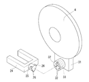
- the disassembled perspective view which shows the connection aspect of the connection member and arm which are shown to FIG.
- FIG. 5A Side view showing essential parts of FIG. 5A
- the front view of the connection member used for the actuator of the continuously variable transmission shown in FIG. The left view of the connection member used for the actuator of the continuously variable transmission shown in FIG.
- the right view of the connection member used for the actuator of the continuously variable transmission shown in FIG. The top view of the connection member used for the actuator of the continuously variable transmission shown in FIG.
- FIG. 9A Left side view of movable pulley and arm used for actuator of continuously variable transmission shown in FIG. Front view of movable pulley and arm used for actuator of continuously variable transmission shown in FIG. Bottom view of movable pulley and arm used for actuator of continuously variable transmission shown in FIG.
- the disassembled perspective view which shows the connection structure of the connection member shown to FIG. 7A, and the arm shown to FIG. 10A.
- the side view which shows the principal part of the connection structure of the connection member shown to FIG. 7A, and the arm shown to FIG. 10A.
- the left view of the connection member used for the actuator of the continuously variable transmission shown in FIG. The right view of the connection member used for the actuator of the continuously variable transmission shown in FIG.
- the top view of the connection member used for the actuator of the continuously variable transmission shown in FIG. 14 is a longitudinal sectional view showing a state in which the connecting member shown in FIG. 14A is fixed to the ball screw nut.
- FIG. 13 is a longitudinal sectional view showing another example of the guide member used for the actuator of the continuously variable transmission shown in FIG.
- the continuously variable transmission includes a main driving shaft 1 connected to the output shaft side of the engine, a main driving side pulley 2 provided on the main driving shaft 1, and a fixed sheave 3 and a movable sheave 4 that constitute the main driving side pulley 2.
- An actuator 5 that is separated, a driven shaft 6 that transmits power to the wheels, a driven pulley 7 provided on the driven shaft 6, and a transmission belt 8 that transmits the rotational force of the driven pulley 2 to the driven pulley 7. It is a major component.
- Opposed taper surfaces are formed on the fixed sheave 3 and the movable sheave 4 constituting the main driving pulley 2, respectively.
- a motor 10 is provided in the motor case 9 of the continuously variable transmission, and an output gear 11 provided on the output shaft of the motor 10 meshes with a gear of a parallel shaft reducer 13 housed in a reducer case 12. Yes.
- the parallel shaft speed reducer 13 includes a first gear 14 that meshes with the output gear 11, a second gear 16 that is attached to the same rotation shaft 15 as the first gear 14, and a third gear 17 that meshes with the second gear 16. Consists of The first gear 14, the second gear 16, and the third gear 17 are all spur gears.
- the rotating shaft 15 to which the first gear 14 and the second gear 16 are attached is supported by a shell bearing 18 so as to be rotatable around the shaft.
- a holding shaft 19 is fitted in the center of the third gear 17.
- the holding shaft body 19 is supported by two four-point contact ball bearings 20 and 20 so as to be rotatable around the axis.
- a deep groove ball bearing can also be used.
- the number of bearings 20 is not limited to two, and may be one.
- a ball screw shaft 21 a as a rotating member 21 is fitted into the end of the holding shaft 19 opposite to the end fitted into the third gear 17.
- a fixing member 22 is inserted into the ball screw shaft 21a in a direction perpendicular to the axial direction of the ball screw shaft 21a, and the holding shaft body 19 and the ball screw shaft 21a rotate together around the axis by the fixing member 22. ing.
- the ball screw shaft 21 a is provided with a ball screw nut 23 a as the displacement member 23.
- a male screw groove is formed on the outer peripheral surface of the ball screw shaft 21a, and a female screw groove is formed on the inner peripheral surface of the ball screw nut 23a at the same pitch as that of the male screw groove.
- a circulation path (not shown) is formed in the ball screw nut 23a from one end side to the other end side of the ball screw nut 23a and facing both the grooves at both ends. As the ball circulates through the gap between the grooves and the circulation path, the ball screw nut 23a is displaced relative to the ball screw shaft 21a in the axial direction as the ball screw shaft 21a rotates. To do.
- the ball screw shaft 21a as the rotating member 21 and the ball screw nut 23a as the displacing member 23
- a sliding screw may be used as the rotating member 21, and a sliding nut may be used as the displacement member 23, respectively.
- the connecting member 24 shown in FIGS. 2A to 2D is fixed to the ball screw nut 23a.
- the connecting member 24 is a U-shaped plate-like member, and an engagement shaft body 25 is extended so as to face an arm 31 described later.
- the ball screw nut 23a is integrally fixed with a screw 28 screwed into a screw hole 27 formed in the connecting member 24.
- the connecting member 24 is fitted into a notch groove 30 formed in the guide member 29 shown in FIGS. 4A and 4B.
- the guide member 29 is fixed to the speed reducer case 12.
- the ball screw nut 23a When the ball screw shaft 21a is rotated around the axis by driving the motor 10, the ball screw nut 23a provided on the ball screw shaft 21a rotates relative to the ball screw shaft 21a around the axis.
- the ball screw nut 23 a is fixed by a connecting member 24, and the connecting member 24 is fitted in a guide member 29 fixed to the speed reducer case 12, and the ball screw nut 23 a is attached to the speed reducer case 12.
- it advances and retreats in the axial direction (the direction of the arrow shown in FIG. 1) without rotating around the axis.
- a guide groove 32 that guides the engaging portion 26 in the axial direction of the engaging shaft body 25 is formed on one end side of the arm 31. Further, a locking groove 33 is formed which communicates with the groove bottom of the guide groove 32 and extends in the rotation direction around the axis of the engagement shaft body 25.
- each engagement portion 26 is preferably formed at a rotationally symmetric position on the peripheral surface of the engagement shaft body 25 as shown in this figure in terms of coupling stability, but is shifted from this rotationally symmetric position. It is also allowed to be formed.
- Two double-row angular ball bearings 34 and 34 are provided on the other end side of the arm 31 as release bearings for the main pulley 2, and the arm 31 is connected to the movable sheave 4 via the bearings 34 and 34. Is urged toward the fixed sheave 3 side.
- the bearing 34 By interposing the bearing 34 in this way, it is possible to apply an urging force to the movable sheave 4 that rotates about the axis by the arm 31 that does not rotate relative to the movable sheave 4.
- a deep groove ball bearing can also be used.
- the number of bearings 34 is not limited to two, and may be one.
- FIG. 6 shows a longitudinal sectional view of a second embodiment of the continuously variable transmission according to the present invention.
- the continuously variable transmission includes a main driving shaft 1 connected to the output shaft side of the engine, a main driving side pulley 2 provided on the main driving shaft 1, and a fixed sheave 3 and a movable sheave 4 that constitute the main driving side pulley 2.
- An actuator 5 that is separated, a driven shaft 6 that transmits power to the wheels, a driven pulley 7 provided on the driven shaft 6, and a transmission belt 8 that transmits the rotational force of the driven pulley 2 to the driven pulley 7. It is a major component.
- Opposed taper surfaces are formed on the fixed sheave 3 and the movable sheave 4 constituting the main driving pulley 2, respectively.
- a motor 10 is provided in the motor case 9 of the continuously variable transmission, and an output gear 11 provided on the output shaft of the motor 10 meshes with a gear of a parallel shaft reducer 13 housed in a reducer case 12. Yes.
- the parallel shaft speed reducer 13 includes a first gear 14 that meshes with the output gear 11, a second gear 16 that is attached to the same rotation shaft 15 as the first gear 14, and a third gear 17 that meshes with the second gear 16. Consists of The first gear 14, the second gear 16, and the third gear 17 are all spur gears.
- the rotating shaft 15 to which the first gear 14 and the second gear 16 are attached is supported by a shell bearing 18 so as to be rotatable around the shaft.
- a holding shaft 19 is fitted in the center of the third gear 17.
- the holding shaft body 19 is supported by two four-point contact ball bearings 20 and 20 so as to be rotatable around the axis.
- a deep groove ball bearing can also be used.
- the number of bearings 20 is not limited to two, and may be one.
- a ball screw shaft 21 a as a rotating member 21 is fitted into the end of the holding shaft 19 opposite to the end fitted into the third gear 17.
- a fixing member 22 is inserted into the ball screw shaft 21a in a direction perpendicular to the axial direction of the ball screw shaft 21a, and the holding shaft body 19 and the ball screw shaft 21a rotate together around the axis by the fixing member 22. ing.
- the ball screw shaft 21 a is provided with a ball screw nut 23 a as the displacement member 23.
- a male screw groove is formed on the outer peripheral surface of the ball screw shaft 21a, and a female screw groove is formed on the inner peripheral surface of the ball screw nut 23a at the same pitch as that of the male screw groove.
- a circulation path (not shown) is formed in the ball screw nut 23a from one end side to the other end side of the ball screw nut 23a and facing both the grooves at both ends. As the ball circulates through the gap between the grooves and the circulation path, the ball screw nut 23a is displaced relative to the ball screw shaft 21a in the axial direction as the ball screw shaft 21a rotates. To do.
- the ball screw shaft 21a as the rotating member 21 and the ball screw nut 23a as the displacing member 23
- a sliding screw may be used as the rotating member 21, and a sliding nut may be used as the displacement member 23, respectively.
- the connecting member 24 shown in FIGS. 7A to 7D is fixed to the ball screw nut 23a.
- the connecting member 24 is a U-shaped plate-like member.
- the connecting member 24 includes a rod-like key member that is perpendicular to a direction facing an arm 31 described later and extends in the width direction of the connecting member 24. 35 is provided.
- the ball screw nut 23 a is integrally fixed with a screw 28 screwed into a screw hole 27 formed in the connecting member 24.
- the connecting member 24 is fitted into a notch groove 30 formed in the guide member 29 shown in FIGS. 9A and 9B.
- the guide member 29 is fixed to the speed reducer case 12.
- the ball screw nut 23a When the ball screw shaft 21a is rotated around the axis by driving the motor 10, the ball screw nut 23a provided on the ball screw shaft 21a rotates relative to the ball screw shaft 21a around the axis.
- the ball screw nut 23a is fixed by a connecting member 24. Further, since the connecting member 24 is fitted into a guide member 29 fixed to the speed reducer case 12, the ball screw nut 23a is fixed to the speed reducer case. 12 moves forward and backward in the axial direction (the direction of the arrow shown in FIG. 6) without rotating around the axis.
- a guide groove 36 for guiding the key member 35 in the direction from the connecting member 24 to the arm 31 is formed on one end side of the arm 31.
- a locking groove 37 extends in a fan shape in the rotational direction around the axis with respect to the direction, communicating with the groove bottom of the guide groove 36.
- FIG. 12 after inserting the key member 35 to the bottom of the guide groove 36 and rotating the connecting member 24 and the arm 31 relative to each other by 90 degrees around the axis (see the arrow in this figure), The key member 35 is fitted into the stop groove 37, and the connecting member 24 and the arm 31 are connected and integrated.
- the connecting member 24 and the arm 31 are rotated relative to each other by 90 degrees in the opposite direction, the fitting of the key member 35 into the locking groove 37 is released and the connecting member 24 and the arm 31 are separated. It can be made into the state which carried out.
- the connection member 24 and the arm 31 can be connected and separated by relative rotation, the assembly and disassembly of the actuator 5 can be performed smoothly.
- the actuator 5 can be downsized.
- connection member 24 and the arm 31 can be reliably connected.
- other shapes such as a pin shape and a cylindrical shape may be employed. Can do.
- the relative rotation angle between the connecting member 24 and the arm 31 is not limited to 90 degrees, and can be appropriately determined in an angle range larger than 0 degrees and smaller than 180 degrees.
- a locking groove 37 can be formed.
- Two double-row angular ball bearings 34 and 34 are provided on the other end side of the arm 31 as release bearings for the main pulley 2, and the arm 31 is connected to the movable sheave 4 via the bearings 34 and 34. Is urged toward the fixed sheave 3 side.
- the bearing 34 By interposing the bearing 34 in this way, it is possible to apply an urging force to the movable sheave 4 that rotates about the axis by the arm 31 that does not rotate relative to the movable sheave 4.
- a deep groove ball bearing can also be used.
- the number of bearings 34 is not limited to two, and may be one.
- FIG. 13 shows a longitudinal sectional view of a third embodiment of a continuously variable transmission according to the present invention.
- the continuously variable transmission includes a main driving shaft 1 connected to the output shaft side of the engine, a main driving side pulley 2 provided on the main driving shaft 1, and a fixed sheave 3 and a movable sheave 4 that constitute the main driving side pulley 2.
- An actuator 5 that is separated, a driven shaft 6 that transmits power to the wheels, a driven pulley 7 provided on the driven shaft 6, and a transmission belt 8 that transmits the rotational force of the driven pulley 2 to the driven pulley 7. It is a major component.
- Opposed taper surfaces are formed on the fixed sheave 3 and the movable sheave 4 constituting the main driving pulley 2, respectively.
- a motor 10 is provided in the motor case 9 of the continuously variable transmission, and an output gear 11 provided on the output shaft of the motor 10 meshes with a gear of a parallel shaft reducer 13 housed in a reducer case 12. Yes.
- the parallel shaft speed reducer 13 includes a first gear 14 that meshes with the output gear 11, a second gear 16 that is attached to the same rotation shaft 15 as the first gear 14, and a third gear 17 that meshes with the second gear 16. Consists of The first gear 14, the second gear 16, and the third gear 17 are all spur gears.
- the rotating shaft 15 to which the first gear 14 and the second gear 16 are attached is supported by a shell bearing 18 so as to be rotatable around the shaft.
- a holding shaft 19 is fitted in the center of the third gear 17.
- the holding shaft body 19 is supported by two four-point contact ball bearings 20 and 20 so as to be rotatable around the axis.
- a deep groove ball bearing can also be used.
- the number of bearings is not limited to two and may be one.
- a ball screw shaft 21 a as a rotating member 21 is fitted into the end of the holding shaft 19 opposite to the end fitted into the third gear 17.
- a fixing member 22 is inserted into the ball screw shaft 21a in a direction perpendicular to the axial direction of the ball screw shaft 21a, and the holding shaft body 19 and the ball screw shaft 21a rotate together around the axis by the fixing member 22. ing.
- the ball screw shaft 21 a is provided with a ball screw nut 23 a as the displacement member 23.
- a male screw groove is formed on the outer peripheral surface of the ball screw shaft 21a, and a female screw groove is formed on the inner peripheral surface of the ball screw nut 23a at the same pitch as that of the male screw groove.
- a circulation path (not shown) is formed in the ball screw nut 23a from one end side to the other end side of the ball screw nut 23a and facing both the grooves at both ends. As the ball circulates through the gap between the grooves and the circulation path, the ball screw nut 23a is displaced relative to the ball screw shaft 21a in the axial direction as the ball screw shaft 21a rotates. To do.
- the ball screw shaft 21a as the rotating member 21 and the ball screw nut 23a as the displacing member 23
- a sliding screw may be used as the rotating member 21, and a sliding nut may be used as the displacement member 23, respectively.
- the connecting member 24 shown in FIGS. 14A to 14D is fixed to the ball screw nut 23a.
- the connecting member 24 is an H-shaped plate member.
- the ball screw nut 23a is integrally fixed by a screw 28 screwed into a screw hole 27 formed in the connecting member 24.
- the ball screw nut 23a and the connecting member 24 constitute an output member 43 that outputs the driving force of the motor 10 to the pulley 2.
- the connecting member 24 is fitted into a notch groove 30 formed in the guide member 29 shown in FIGS. 16A and 16B.
- This notch groove 30 does not slide with the connecting member 24 on the connecting side of the connecting member 24 with an arm 31 (to be described later) on the connecting portion 24 and on the side opposite to the connecting side in the axial direction.
- a widened portion 39 has an angle of 3 degrees or more with respect to the parallel portion 38 and is a tapered surface continuous with the parallel portion 38. While the connecting member 24 is reliably guided in the axial direction by the parallel portion 38, the widened portion 39 prevents contact between the connecting member 24 and the guide member 29, and the sliding between the connecting member 24 and the guide member 29 is prevented. Friction caused by movement can be minimized.
- the guide member 29 is fixed to the speed reducer case 12.
- the ball screw nut 23a provided on the ball screw shaft 21a rotates relative to the ball screw shaft 21a around the axis.
- the ball screw nut 23 a is fixed by a connecting member 24, and the connecting member 24 is fitted in a guide member 29 fixed to the speed reducer case 12, and the ball screw nut 23 a is attached to the speed reducer case 12. It moves forward and backward in the axial direction (the direction of the arrow shown in FIG. 13) without rotating around the axis.
- the connecting member 24 is fixed to one end side of the arm 31. Both are fixed by press-fitting a common press-fit pin 41 into the pin hole 40 formed in the connecting member 24 and the pin hole 40 formed in the arm 31.
- the actuator 5 can be assembled and disassembled smoothly.
- the connecting structure of the connecting member 24 and the arm 31 according to the first embodiment or the second embodiment (see FIG. 5A, FIG. 11, etc.). It can also be adopted.
- Two double-row angular ball bearings 34 and 34 are provided on the other end side of the arm 31 as release bearings for the main pulley 2, and the arm 31 is connected to the movable sheave 4 via the bearings 34 and 34. Is urged toward the fixed sheave 3 side.
- the bearing 34 By interposing the bearing 34 in this way, it is possible to apply an urging force to the movable sheave 4 that rotates about the axis by the arm 31 that does not rotate relative to the movable sheave 4.
- a deep groove ball bearing can also be used.
- the number of bearings 34 is not limited to two, and may be one.
- a lubrication layer such as a solid lubrication treatment layer (deflick coat) may be formed on the parallel portion 38 of the guide member 29 shown in FIGS. 16A and 16B.
- a resin material can be used as a material at least in the vicinity of the parallel portion 38 of the guide member 29.
- this resin material has higher solid lubricity than other materials such as metal materials, the movable sheave 4 can be smoothly moved with respect to the fixed sheave 3 as in the case where the lubricating layer is formed on the sliding surface. You can touch and leave.
- this resin material for example, a fluororesin excellent in slidability and heat resistance can be employed.
- FIG. 29 Another example of the guide member 29 is shown in FIG.
- the guide member 29 has a notch groove 30 formed in the same manner as the guide member 29 shown in FIGS. 16A and 16B, and the notch groove 30 is common in that it has a parallel portion 38 and a widened portion 39.
- an enlarged portion 42 that partially enlarges the groove width of the notched groove 30 is formed on the inner surface of the parallel portion 38.
- the enlarged portion 42 can be formed in a groove shape as shown in FIG. By forming the enlarged portion 42, the wear powder generated by the friction between the connecting member 24 and the guide member 29 is accumulated and held in the enlarged portion 42, and the wear powder is retained in the ball screw shaft 21a. Can be prevented. For this reason, the lifetime of the actuator 5 can be further extended.
- the number (number) and shape of the enlarged portions 42 are not particularly limited.
- the above embodiment is merely an example, and it is possible to easily assemble and disassemble the actuator 5, and to solve the problem of the present invention of improving the durability, the shape of each member and The arrangement, material, etc. can be changed as appropriate.
Abstract
アクチュエータ(5)が、モータ(10)の駆動力によって回転する回転部材(21)と、回転部材(21)の回転によって軸方向に変位する変位部材(23)と、変位部材(23)に取り付けられる連結部材(24)と、連結部材(24)を軸周りに回転不能としつつ軸方向にガイドするガイド部材(29)と、連結部材(24)と可動シーブ(4)との間に接続されるアーム(31)とを備えた無段変速機用アクチュエータを構成して、その組み付け及び分解が容易に行えるようにするとともに、その耐久性も向上させる。
Description
この発明は、例えば小型二輪車等の車両に用いられる無段変速機用アクチュエータ及び無段変速機に関する。
無段変速機は、主動側プーリ、従動側プーリ、及び両プーリ間に巻き付けられた伝達ベルトを有し、両プーリをそれぞれ構成する固定シーブと可動シーブとの間の距離を変えることによって主動側プーリ及び従動側プーリに巻き付けられた伝達ベルトの巻き径を連続的に変えることによって、変速比を無段階で調整し得るようにしたものである。
この可動シーブを固定シーブに対して接離させるために、例えば下記特許文献1に示すように、遠心ローラ式の駆動機構を採用することがある。この駆動機構は、本文献の図3等に示すように、出力軸の回転が上がると、遠心力によって遠心ローラが外側に移動し、バネの付勢力に抗して、クラッチ板をプーリ(可動シーブ)側に押し付ける。このプーリの押し付けによって、プーリ間(可動シーブと固定シーブとの間)の間隔が狭くなり、変速比の変更がなされる。
この遠心ローラ式の駆動機構は、遠心力の作用で移動した遠心ローラによって間接的にプーリを駆動するため、例えば遠心ローラの動きに引っ掛かり等の不具合が生じると、プーリの高い駆動精度を得ることができない。この場合、エンジンの回転数や速度に対応して最適な変速比とすることができず、駆動系における十分な燃費向上効果が得られないという問題がある。そこで、下記特許文献2、3においては、可動シーブを遠心ローラ式ではなく、モータを駆動源とするアクチュエータによって直接駆動する構成を採用している。
特許文献2に係る無段変速機は、本文献の図1等に記載のように、モータの回転軸を軸周りに回転させることによってナット部材を回転させる。このナット部材を回転させると、このナット部材と噛み合うねじ軸が軸方向に変位する。このねじ軸の変位に伴って、押圧部材も同方向に変位し、フォーク部材を所定方向に回動させる。この回動に伴って可動シーブが押圧されて、可動シーブが固定シーブに接近する。
特許文献3に係る無段変速機は、本文献の図4等に記載のように、アクチュエータユニットにより出力軸を駆動させて、その駆動方向にアーム部材を進退させることによって、可動プーリを移動させる。アーム部材は、連結部材を介してアクチュエータユニットの出力軸に連結される。
特許文献2に係る構成においては、軸方向への駆動にねじ軸を用いており、このねじ軸がねじ軸室内において、軸線方向への相対移動を許容しつつ、相対回転を阻止するようにするために、回り止めを設けなければならない(本文献の段落0046参照)。そのため、アクチュエータの構成が煩雑になる問題がある。また、ねじ軸の回転によって駆動させる機構のため、この回転に伴うモーメントが周囲の部材に負荷され、この部材の短寿命化を引き起こすおそれもある。
また、特許文献3に係る構成においては、アクチュエータユニットとアーム部材を、組み付け時及び部品交換時の度に着脱しなければならない。この着脱は、アーム部材側に取り付けられたピンに、アクチュエータユニットの出力軸先端に設けられたフック部を引っ掛けたり、取り外したりことによって行われるが、その際にフック部を横から(本文献の図4の右側から)スライドさせなければならず、この作業を行うためには、ピンとフック部との間にある程度の隙間を設けておく必要がある。このため、アクチュエータユニットの小型化に支障を来たすおそれがある。
ピンとフック部を始めから一体化しておく構成も考えられるが、この場合、組み付けの容易性は向上するものの、アクチュエータのメンテナンスにおいて分解する必要が生じた際に、作業に手間取る問題がある。
そこで、この発明は、アクチュエータの組み付け及び分解を容易に行い得る構成とするとともに、その耐久性を向上することを課題とする。
この課題を解決するために、この発明においては、固定シーブとこの固定シーブと対をなす可動シーブとを有するプーリと、前記可動シーブを前記固定シーブに対して軸方向に接離させるアクチュエータと、を備えた無段変速機用アクチュエータにおいて、前記アクチュエータが、モータの駆動力によって回転する回転部材と、前記回転部材の回転によって軸方向に変位する変位部材と、前記変位部材に取り付けられる連結部材と、前記連結部材を軸周りに回転不能としつつ軸方向にガイドするガイド部材と、前記連結部材と前記可動シーブとの間に接続されるアームと、を備えた無段変速機用アクチュエータを構成した。
このように、ガイド部材で、変位部材を取り付けた連結部材を軸周りに回転不能にガイドすることにより、回り止めのための部材を別途設ける必要がない。また、連結部材とアームとの間を接続式とすることにより、アクチュエータを構成する各部材を簡便化することができる。このため、アクチュエータの組み付け及び分解を容易に行い得るとともに、その耐久性を向上することができる。
前記構成においては、前記連結部材又は前記アームの一方側は、前記連結部材又は前記アームの他方側に臨むように延設された係合軸体と、この係合軸体からその径方向に突出する係合部と、を有し、前記連結部材又は前記アームの他方側は、前記係合部を前記係合軸体の軸方向に案内する案内溝と、この案内溝の溝底と連通し、前記係合軸体の軸周り回転方向に延設された係止溝と、を有し、前記係合部を前記案内溝の溝底まで挿入した上で、前記連結部材と前記アームとを軸周りに相対回転して前記係止溝に前記係合部が嵌り込むようにすることができる。
このように、連結部材又はアームの一方側の係止溝に、他方側の係合部が嵌り込むことによって、連結部材とアームが確実に係合する。このため、アクチュエータの駆動により、固定シーブに対して可動シーブをスムーズに接離することができる。
連結部材とアームとの係合は、両者を軸周りに所定角度だけ相対回転することによってなされる。また、その係合の解除は、両者を軸周りの逆方向に所定角度だけ相対回転することによってなされる。このように、両者を軸周りに相対回転するだけで着脱することができるため、アクチュエータの組み付け及び分解作業を一層スムーズに行うことができる。
前記係合軸体等を採用した構成においては、前記係合部が、前記係合軸体の軸周りに、回転対称に2個以上形成されている構成とするのが好ましい。係合部を2個以上形成することにより、連結部材とアームを、がたつきなく確実に連結することができる。
前記係合軸体等を採用した各構成においては、前記モータの回転を減速して前記回転部材に伝達する遊星減速機又は平行軸減速機をさらに備えた構成とするのが好ましい。このように、各種減速機を用いることで、適切な速度で回転部材を軸周りに回転させて、プーリの変速比の変更をスムーズに行うことができる。
前記係合軸体等を採用した各構成においては、前記可動シーブと前記アームとの間に、複列アンギュラ玉軸受又は深溝玉軸受を設けた構成とするのが好ましい。このように、各種軸受を設けることにより、アームから可動シーブに対して、この可動シーブを固定シーブに接近させる押圧力を与えつつ、この可動シーブを軸周りに回転自在とすることができる。この軸受の個数は、1~2個とするのが好ましいが、その数は適宜変更することができる。
前記係合軸体等を採用した各構成においては、前記回転部材を4点接触玉軸受又は深溝玉軸受で支持する構成とするのが好ましい。このように、各種軸受を設けることにより、回転部材をその軸周りに安定して回転させることができる。この軸受の個数は、1~2個とするのが好ましいが、その数は適宜変更することができる。
上記のように、係合軸体等を採用した構成の代わりに、前記連結部材又は前記アームの一方側は、前記連結部材又は前記アームの他方側に臨む方向に対して垂直なキー部材を有し、前記連結部材又は前記アームの他方側は、前記キー部材を前記方向に案内する案内溝と、この案内溝の溝底と連通し、前記方向に対して軸周り回転方向に延設された係止溝と、を有し、前記キー部材を前記案内溝の溝底まで挿入した上で、前記連結部材と前記アームとを軸周りに相対回転して前記係止溝に前記キー部材が嵌り込むようにすることもできる。
このように、連結部材又はアームの一方側の係止溝に他方側のキー部材が嵌り込むことによって、連結部材とアームが確実に係合する。このため、アクチュエータの駆動により、固定シーブに対して可動シーブをスムーズに接離することができる。
連結部材とアームとの係合は、両者を軸周りに所定角度だけ相対回転することによってなされる。また、その係合の解除は、両者を軸周りの逆方向に所定角度だけ相対回転することによってなされる。このように、両者を軸周りに相対回転するだけで着脱することができるため、アクチュエータの組み付け及び分解作業を一層スムーズに行うことができる。
前記キー部材等を採用した構成においては、前記キー部材が、前記連結部材の幅方向に亘って設けられた棒状部材である構成とするのが好ましい。このように、棒状部材を配置することにより、棒状部材の全幅に亘ってアームとの係合部を押し引きすることができ、このアームによる可動シーブの接離をスムーズに行うことができる。
前記キー部材等を採用した各構成においては、前記係止溝が、前記案内溝から前記軸周り回転方向に、0度よりも大きく180度よりも小さい角度範囲に亘って、扇状に形成されている構成とするのが好ましい。このようにすれば、係止溝によりキー部材を確実に係止して、アームによる可動シーブの接離を一層スムーズに行うことができる。
前記各構成においては、前記回転部材がボールねじ軸で、前記変位部材がボールねじナットである構成とするのが好ましい。このアクチュエータは、回転運動を直線運動に変換するとともに、モータの駆動力のON・OFFに対応して、この直線運動の範囲内の所定位置で正確に停止させる高い制御性が要求されるところ、回転部材としてボールねじ軸を使用するとともに、変位部材としてボールねじナットを使用することにより、回転運動の直線運動への変換と、停止位置の高い制御性の両立を図ることができる。
前記各構成においては、前記ガイド部材には、前記回転部材の回転によって軸方向に変位する前記アームに固定された出力部材をガイドする切欠き溝が形成されており、この切欠き溝は、前記出力部材の前記アームとの連結側に、前記出力部材と摺動する平行部と、前記連結側と軸方向反対側に、前記出力部材と摺動しない拡幅部とを有する構成とするのが好ましい。
このように、ガイド部材の切欠き溝を平行部と拡幅部で構成することにより、平行部で出力部材を軸方向に確実にガイドしつつ、拡幅部において出力部材とガイド部材との接触を防止して、この出力部材とガイド部材との間の摺動に起因する摩擦を極力小さくすることができる。しかも、この平行部を出力部材のアームとの連結側(回転部材が設けられている側とは反対側)に形成したので、出力部材と平行部が摺動して摩擦粉が発生したとしても、この摩擦粉が出力部材の回転部材側に到達しにくい。このため、アクチュエータの長寿命化を図って、長期間に亘ってアクチュエータを安定的に動作させることができる。
前記切欠き溝が形成された構成においては、前記出力部材が、前記回転部材を受ける変位部材と、前記変位部材に対して固定されて前記ガイド部材によってガイドされるとともに、前記アームに接続される連結部材と、を備えた構成とすることができる。
前記切欠き溝が形成された各構成においては、前記拡幅部を、前記平行部と連続するテーパ面によって構成するのが好ましい。テーパ面とすることにより、ガイド部材を鋳造成形する際の離型性を高めることができる。このテーパ面のテーパ角度は、3度以上とするのが好ましい。
前記切欠き溝が形成された各構成においては、前記平行部の内面に、前記切欠き溝の溝幅を部分的に拡大する拡大部を形成した構成とするのが好ましい。このように拡大部を形成することにより、摩耗粉が拡大部内に溜まって保持された状態となり、この摩耗粉が回転部材に到達するのを一層防止することができる。このため、アクチュエータのさらなる長寿命化を図ることができる。
上記第一構成に係る無段変速機用アクチュエータを無段変速機に適用することによって、車両に搭載したエンジンの回転数や速度に対応して最適な変速比とすることができ、駆動系における高い燃費向上効果を得ることができる。
この発明に係る無段変速機の第一実施形態の縦断面図を図1に示す。この無段変速機は、エンジンの出力軸側に接続される主動軸1と、主動軸1に設けられる主動側プーリ2と、主動側プーリ2を構成する固定シーブ3と可動シーブ4を互いに接離するアクチュエータ5と、車輪に動力を伝達する従動軸6と、従動軸6に設けられる従動側プーリ7と、主動側プーリ2の回転力を従動側プーリ7に伝達する伝達ベルト8と、を主要な構成要素としている。
主動側プーリ2を構成する固定シーブ3と可動シーブ4には、対向するテーパ面がそれぞれ形成されている。固定シーブ3に対して可動シーブ4を軸方向に接離することによって、両シーブ3、4間の距離が変化し、この主動側プーリ2で駆動される伝達ベルト8の回転半径を連続的に変化させることができる。
アクチュエータ5の構成について説明する。無段変速機のモータケース9内にはモータ10が設けられ、このモータ10の出力軸に設けられた出力ギア11は、減速機ケース12に収納された平行軸減速機13のギアと噛み合っている。この平行軸減速機13は、出力ギア11と噛み合う第一ギア14と、第一ギア14と同一の回転軸15に取り付けられた第二ギア16と、第二ギア16と噛み合う第三ギア17とから構成される。この第一ギア14、第二ギア16、及び第三ギア17は、いずれも平歯車である。第一ギア14及び第二ギア16が取り付けられた回転軸15は、シェル軸受18によって軸周りに回転自在に支持されている。
第三ギア17の中心には保持軸体19が嵌め込まれている。この保持軸体19は、2個の4点接触玉軸受20、20によって、軸周りに回転自在に支持されている。4点接触玉軸受20を使用する代わりに深溝玉軸受を使用することもできる。また、軸受20の個数は2個に限られず、1個とすることもできる。保持軸体19の第三ギア17に嵌め込まれた端部と反対側の端部には、回転部材21としてボールねじ軸21aが嵌め込まれている。このボールねじ軸21aには固定部材22がその軸方向と垂直の方向に挿し込まれており、この固定部材22によって、保持軸体19とボールねじ軸21aが軸周りに共回りするようになっている。
ボールねじ軸21aには、変位部材23としてボールねじナット23aが設けられている。ボールねじ軸21aの外周面には雄ねじ溝が、ボールねじナット23aの内周面には前記雄ねじ溝と同じピッチで雌ねじ溝がそれぞれ形成され、両溝の間には複数のボールが収納されている。また、ボールねじナット23a内には、ボールねじナット23aの一端側から他端側に至るとともに、この両端で前記両溝に臨む循環路(図示せず)が形成されている。前記両溝の間の隙間及び前記循環路を通ってボールが循環することによって、ボールねじ軸21aの回転に伴って、ボールねじナット23aがボールねじ軸21aに対して軸方向に相対的に変位する。
このように、回転部材21としてボールねじ軸21a、変位部材23としてボールねじナット23aを採用することにより、回転運動の直線運動への変換と、停止位置の高い制御性の両立を図ることができるが、ボールねじ軸21a及びボールねじナット23aの代わりに、回転部材21として滑りねじ、前記変位部材23として滑りナットをそれぞれ用いてもよい。
このボールねじナット23aには、図2A~図2Dに示す連結部材24が固定されている。この連結部材24は、コの字形の板状部材であり、後述するアーム31に臨むように係合軸体25が延設されている。この係合軸体25の周面には、120度回転対称形の係合部26がその径方向外向きに突出して3個形成されている。
図3に示すように、ボールねじナット23aは、連結部材24に形成されたねじ孔27にねじ込まれたねじ28で一体に固定された状態となっている。この連結部材24は、図4A及び図4Bに示すガイド部材29に形成された切欠き溝30に嵌め込まれる。このガイド部材29は、減速機ケース12に固定されている。
モータ10の駆動によって、ボールねじ軸21aを軸周りに回転すると、このボールねじ軸21aに設けられたボールねじナット23aがボールねじ軸21aに対して軸周りに相対回転する。このボールねじナット23aは、連結部材24によって固定されており、しかも、この連結部材24は減速機ケース12に固定されたガイド部材29に嵌め込まれており、ボールねじナット23aは減速機ケース12に対して軸周りに回転することなく、軸方向(図1中に示す矢印の方向)に進退する。
図5A及び図5Bに示すように、アーム31の一端側には、係合部26を係合軸体25の軸方向に案内する案内溝32が形成されている。さらに、この案内溝32の溝底と連通し、係合軸体25の軸周り回転方向に延設された係止溝33が形成されている。係合部26を案内溝32の溝底まで挿入した上で、連結部材24とアーム31とを軸周りに相対回転すると、係止溝33に係合部26が嵌り込んで、連結部材24とアーム31が連結されて一体化した状態となる。
その一方で、連結部材24とアーム31を連結時とは逆方向に相対回転すると、係止溝33への係合部26の嵌り込みが解除されて、連結部材24とアーム31とを分離した状態とすることができる。このように、連結部材24とアーム31の相対回転によって、両者の連結及び分離を行い得るようにしたので、アクチュエータ5の組み付け及び分解作業をスムーズに行うことができる。しかも、この作業を行うために連結部材24及びアーム31の周囲に空間を確保する必要がないため、アクチュエータ5の小型化を図ることができる。
図5A等には、係合軸体25の周面に、3個の係合部26を形成した例について示したが、係合部26の個数は2個以上であれば特に限定されない。また、各係合部26は本図に示すように係合軸体25の周面における回転対称の位置に形成するのが結合安定性の面で好ましいが、この回転対称の位置からずれた位置に形成することも許容される。
アーム31の他端側には、主動側プーリ2のレリーズ軸受として、2個の複列アンギュラ玉軸受34、34が設けられており、この軸受34、34を介して、アーム31が可動シーブ4を固定シーブ3側に付勢するようになっている。このように軸受34を介在させることにより、軸周りに回転する可動シーブ4に、この可動シーブ4に対して相対回転しないアーム31で付勢力を与えることができる。複列アンギュラ玉軸受34を使用する代わりに、深溝玉軸受を使用することもできる。また、軸受34の個数は2個に限られず、1個とすることもできる。
この発明に係る無段変速機の第二実施形態の縦断面図を図6に示す。この無段変速機は、エンジンの出力軸側に接続される主動軸1と、主動軸1に設けられる主動側プーリ2と、主動側プーリ2を構成する固定シーブ3と可動シーブ4を互いに接離するアクチュエータ5と、車輪に動力を伝達する従動軸6と、従動軸6に設けられる従動側プーリ7と、主動側プーリ2の回転力を従動側プーリ7に伝達する伝達ベルト8と、を主要な構成要素としている。
主動側プーリ2を構成する固定シーブ3と可動シーブ4には、対向するテーパ面がそれぞれ形成されている。固定シーブ3に対して可動シーブ4を軸方向に接離することによって、両シーブ3、4間の距離が変化し、この主動側プーリ2で駆動される伝達ベルト8の回転半径を連続的に変化させることができる。
アクチュエータ5の構成について説明する。無段変速機のモータケース9内にはモータ10が設けられ、このモータ10の出力軸に設けられた出力ギア11は、減速機ケース12に収納された平行軸減速機13のギアと噛み合っている。この平行軸減速機13は、出力ギア11と噛み合う第一ギア14と、第一ギア14と同一の回転軸15に取り付けられた第二ギア16と、第二ギア16と噛み合う第三ギア17とから構成される。この第一ギア14、第二ギア16、及び第三ギア17は、いずれも平歯車である。第一ギア14及び第二ギア16が取り付けられた回転軸15は、シェル軸受18によって軸周りに回転自在に支持されている。
第三ギア17の中心には保持軸体19が嵌め込まれている。この保持軸体19は、2個の4点接触玉軸受20、20によって、軸周りに回転自在に支持されている。4点接触玉軸受20を使用する代わりに深溝玉軸受を使用することもできる。また、軸受20の個数は2個に限られず、1個とすることもできる。保持軸体19の第三ギア17に嵌め込まれた端部と反対側の端部には、回転部材21としてボールねじ軸21aが嵌め込まれている。このボールねじ軸21aには固定部材22がその軸方向と垂直の方向に挿し込まれており、この固定部材22によって、保持軸体19とボールねじ軸21aが軸周りに共回りするようになっている。
ボールねじ軸21aには、変位部材23としてボールねじナット23aが設けられている。ボールねじ軸21aの外周面には雄ねじ溝が、ボールねじナット23aの内周面には前記雄ねじ溝と同じピッチで雌ねじ溝がそれぞれ形成され、両溝の間には複数のボールが収納されている。また、ボールねじナット23a内には、ボールねじナット23aの一端側から他端側に至るとともに、この両端で前記両溝に臨む循環路(図示せず)が形成されている。前記両溝の間の隙間及び前記循環路を通ってボールが循環することによって、ボールねじ軸21aの回転に伴って、ボールねじナット23aがボールねじ軸21aに対して軸方向に相対的に変位する。
このように、回転部材21としてボールねじ軸21a、変位部材23としてボールねじナット23aを採用することにより、回転運動の直線運動への変換と、停止位置の高い制御性の両立を図ることができるが、ボールねじ軸21a及びボールねじナット23aの代わりに、回転部材21として滑りねじ、前記変位部材23として滑りナットをそれぞれ用いてもよい。
このボールねじナット23aには、図7A~図7Dに示す連結部材24が固定されている。連結部材24は、コの字形の板状部材であり、この連結部材24には、後述するアーム31に臨む方向に対して垂直に、かつ連結部材24の幅方向に亘って、棒状のキー部材35が設けられている。
図8に示すように、ボールねじナット23aは、連結部材24に形成されたねじ孔27にねじ込まれたねじ28で一体に固定された状態となっている。この連結部材24は、図9A及び図9Bに示すガイド部材29に形成された切欠き溝30に嵌め込まれる。このガイド部材29は減速機ケース12に固定されている。
モータ10の駆動によって、ボールねじ軸21aを軸周りに回転すると、このボールねじ軸21aに設けられたボールねじナット23aがボールねじ軸21aに対して軸周りに相対回転する。このボールねじナット23aは、連結部材24によって固定されており、しかも、この連結部材24は、減速機ケース12に固定されたガイド部材29に嵌め込まれているため、ボールねじナット23aは減速機ケース12に対して軸周りに回転することなく、軸方向(図6中に示す矢印の方向)に進退する。
図10A~図10C及び図11に示すように、アーム31の一端側には、連結部材24からアーム31に臨む方向にキー部材35を案内する案内溝36が形成されている。さらに、この案内溝36の溝底と連通し、前記方向に対して軸周り回転方向に扇状に係止溝37が延設されている。図12に示すように、キー部材35を案内溝36の溝底まで挿入した上で、連結部材24とアーム31とを軸周りに90度相対回転すると(本図中の矢印を参照)、係止溝37にキー部材35が嵌り込んで、連結部材24とアーム31が連結されて一体化した状態となる。
その一方で、連結部材24とアーム31を連結時とは逆方向に90度相対回転すると、係止溝37へのキー部材35の嵌り込みが解除されて、連結部材24とアーム31とを分離した状態とすることができる。このように、連結部材24とアーム31の相対回転によって、両者の連結及び分離を行い得るようにしたので、アクチュエータ5の組み付け及び分解作業をスムーズに行うことができる。しかも、この作業を行うために連結部材24及びアーム31の周囲に空間を確保する必要がないため、アクチュエータ5の小型化を図ることができる。
上記の実施形態においては、キー部材35を棒状とした例について示したが、連結部材24とアーム31の連結を確実に行い得る限りにおいて、ピン状や円筒状等の他の形状も採用することができる。また、連結部材24とアーム31との間の相対回転角度は、90度に限定されず、0度よりも大きく180度よりも小さい角度範囲で適宜決めることができ、この角度範囲に対応して係止溝37を形成することができる。
アーム31の他端側には、主動側プーリ2のレリーズ軸受として、2個の複列アンギュラ玉軸受34、34が設けられており、この軸受34、34を介して、アーム31が可動シーブ4を固定シーブ3側に付勢するようになっている。このように軸受34を介在させることにより、軸周りに回転する可動シーブ4に、この可動シーブ4に対して相対回転しないアーム31で付勢力を与えることができる。複列アンギュラ玉軸受34を使用する代わりに、深溝玉軸受を使用することもできる。また、軸受34の個数は2個に限られず、1個とすることもできる。
この発明に係る無段変速機の第三実施形態の縦断面図を図13に示す。この無段変速機は、エンジンの出力軸側に接続される主動軸1と、主動軸1に設けられる主動側プーリ2と、主動側プーリ2を構成する固定シーブ3と可動シーブ4を互いに接離するアクチュエータ5と、車輪に動力を伝達する従動軸6と、従動軸6に設けられる従動側プーリ7と、主動側プーリ2の回転力を従動側プーリ7に伝達する伝達ベルト8と、を主要な構成要素としている。
主動側プーリ2を構成する固定シーブ3と可動シーブ4には、対向するテーパ面がそれぞれ形成されている。固定シーブ3に対して可動シーブ4を軸方向に接離することによって、両シーブ3、4間の距離が変化し、この主動側プーリ2で駆動される伝達ベルト8の回転半径を連続的に変化させることができる。
アクチュエータ5の構成について説明する。無段変速機のモータケース9内にはモータ10が設けられ、このモータ10の出力軸に設けられた出力ギア11は、減速機ケース12に収納された平行軸減速機13のギアと噛み合っている。この平行軸減速機13は、出力ギア11と噛み合う第一ギア14と、第一ギア14と同一の回転軸15に取り付けられた第二ギア16と、第二ギア16と噛み合う第三ギア17とから構成される。この第一ギア14、第二ギア16、及び第三ギア17は、いずれも平歯車である。第一ギア14及び第二ギア16が取り付けられた回転軸15は、シェル軸受18によって軸周りに回転自在に支持されている。
第三ギア17の中心には保持軸体19が嵌め込まれている。この保持軸体19は、2個の4点接触玉軸受20、20によって、軸周りに回転自在に支持されている。4点接触玉軸受20を使用する代わりに深溝玉軸受を使用することもできる。また、軸受の個数は2個に限られず、1個とすることもできる。保持軸体19の第三ギア17に嵌め込まれた端部と反対側の端部には、回転部材21としてボールねじ軸21aが嵌め込まれている。このボールねじ軸21aには固定部材22がその軸方向と垂直の方向に挿し込まれており、この固定部材22によって、保持軸体19とボールねじ軸21aが軸周りに共回りするようになっている。
ボールねじ軸21aには、変位部材23としてボールねじナット23aが設けられている。ボールねじ軸21aの外周面には雄ねじ溝が、ボールねじナット23aの内周面には前記雄ねじ溝と同じピッチで雌ねじ溝がそれぞれ形成され、両溝の間には複数のボールが収納されている。また、ボールねじナット23a内には、ボールねじナット23aの一端側から他端側に至るとともに、この両端で前記両溝に臨む循環路(図示せず)が形成されている。前記両溝の間の隙間及び前記循環路を通ってボールが循環することによって、ボールねじ軸21aの回転に伴って、ボールねじナット23aがボールねじ軸21aに対して軸方向に相対的に変位する。
このように、回転部材21としてボールねじ軸21a、変位部材23としてボールねじナット23aを採用することにより、回転運動の直線運動への変換と、停止位置の高い制御性の両立を図ることができるが、ボールねじ軸21a及びボールねじナット23aの代わりに、回転部材21として滑りねじ、前記変位部材23として滑りナットをそれぞれ用いてもよい。
このボールねじナット23aには、図14A~図14Dに示す連結部材24が固定されている。この連結部材24はH字形の板状部材であり、図15に示すように、ボールねじナット23aは、連結部材24に形成されたねじ孔27にねじ込まれたねじ28で一体に固定された状態となっており、このボールねじナット23aと連結部材24で、モータ10の駆動力をプーリ2に出力する出力部材43が構成される。
連結部材24は、図16A及び図16Bに示すガイド部材29に形成された切欠き溝30に嵌め込まれる。この切欠き溝30は、連結部材24の後述するアーム31との連結側に、連結部材24と摺動する平行部38と、前記連結側と軸方向反対側に、連結部材24と摺動しない拡幅部39とを有する。この拡幅部39は、平行部38に対して3度以上の角度を有し、この平行部38と連続するテーパ面となっている。この平行部38で連結部材24を軸方向に確実にガイドしつつ、拡幅部39において連結部材24とガイド部材29との接触を防止して、この連結部材24とガイド部材29との間の摺動に起因する摩擦を極力小さくすることができる。
ガイド部材29は減速機ケース12に固定されている。モータ10の駆動によって、ボールねじ軸21aを軸周りに回転すると、このボールねじ軸21aに設けられたボールねじナット23aがボールねじ軸21aに対して軸周りに相対回転する。このボールねじナット23aは連結部材24によって固定されており、しかもこの連結部材24は減速機ケース12に固定されたガイド部材29に嵌め込まれており、ボールねじナット23aは減速機ケース12に対して軸周りに回転することなく、軸方向(図13中に示す矢印の方向)に進退する。
この連結部材24は、アーム31の一端側に固定されている。両者の固定は、連結部材24に形成したピン孔40及びアーム31に形成したピン孔40に、共通の圧入ピン41を圧入することによってなされている。このように、連結部材24とアーム31を予め圧入ピン41で一体化しておくことで、アクチュエータ5の組み付け及び分解をスムーズに行うことができる。なお、圧入ピン41の圧入により連結部材24とアーム31を連結する代わりに、第一実施形態又は第二実施形態に係る連結部材24とアーム31の連結構造(図5A、図11等参照)を採用することもできる。
アーム31の他端側には、主動側プーリ2のレリーズ軸受として、2個の複列アンギュラ玉軸受34、34が設けられており、この軸受34、34を介して、アーム31が可動シーブ4を固定シーブ3側に付勢するようになっている。このように軸受34を介在させることにより、軸周りに回転する可動シーブ4に、この可動シーブ4に対して相対回転しないアーム31で付勢力を与えることができる。複列アンギュラ玉軸受34を使用する代わりに、深溝玉軸受を使用することもできる。また、軸受34の個数は2個に限られず、1個とすることもできる。
図16A及び図16Bに示すガイド部材29の平行部38に、例えば固体潤滑処理層(デフリックコート)等の潤滑層を形成してもよい。潤滑層を形成することにより、連結部材24とガイド部材29との間の摺動に起因する摩擦を低減でき、固定シーブ3に対して可動シーブ4をスムーズに接離することができる。このように潤滑層を形成する代わりに、このガイド部材29のうち少なくとも平行部38の付近の素材に樹脂材を使用することもできる。この樹脂材は、金属材等の他の素材と比較して高い固体潤滑性を有するため、摺動面に潤滑層を形成した場合と同様に、固定シーブ3に対して可動シーブ4をスムーズに接離することができる。この樹脂材として、例えば、摺動性及び耐熱性に優れるフッ素樹脂等を採用することができる。
ガイド部材29の他例を図17に示す。このガイド部材29には、図16A及び図16Bに示したガイド部材29と同様に、切欠き溝30が形成され、この切欠き溝30が平行部38と拡幅部39とを有する点で共通するが、この平行部38の内面に、切欠き溝30の溝幅を部分的に拡大する拡大部42を形成した点において異なっている。この拡大部42は、図17に示すように溝状とすることができる。この拡大部42を形成することにより、連結部材24とガイド部材29との間の摩擦によって生じた摩耗粉が、拡大部42内に溜まって保持された状態となり、この摩耗粉がボールねじ軸21aに到達するのを防止することができる。このため、アクチュエータ5の更なる長寿命化を図ることができる。なお、この拡大部42の個数(本数)、形状は特に限定されない。
上記の実施形態はあくまでも一例であって、アクチュエータ5の組み付け及び分解を容易に行い得る構成とするとともに、その耐久性を向上するという本願発明の課題を解決し得る限りにおいて、各部材の形状や配置、素材等は適宜変更することができる。
1 主動軸
2 主動側プーリ(プーリ)
3 固定シーブ
4 可動シーブ
5 アクチュエータ
6 従動軸
7 従動側プーリ
8 伝達ベルト
9 モータケース
10 モータ
11 出力ギア
12 減速機ケース
13 平行軸減速機(減速機)
14 第一ギア
15 回転軸
16 第二ギア
17 第三ギア
18 シェル軸受
19 保持軸体
20 4点接触玉軸受(軸受)
21 回転部材
21a ボールねじ軸
22 固定部材
23 変位部材
23a ボールねじナット
24 連結部材
25 係合軸体
26 係合部
27 ねじ孔
28 ねじ
29 ガイド部材
30 切欠き溝
31 アーム
32、36 案内溝
33、37 係止溝
34 複列アンギュラ玉軸受(軸受)
35 キー部材
38 平行部
39 拡幅部
40 ピン孔
41 圧入ピン
42 拡大部
43 出力部材
Claims (15)
- 固定シーブ(3)とこの固定シーブ(3)と対をなす可動シーブ(4)とを有するプーリ(2)と、前記可動シーブ(4)を前記固定シーブ(3)に対して軸方向に接離させるアクチュエータ(5)と、を備えた無段変速機用アクチュエータにおいて、
前記アクチュエータ(5)が、モータ(10)の駆動力によって回転する回転部材(21)と、前記回転部材(21)の回転によって軸方向に変位する変位部材(23)と、前記変位部材(23)に取り付けられる連結部材(24)と、前記連結部材(24)を軸周りに回転不能としつつ軸方向にガイドするガイド部材(29)と、前記連結部材(24)と前記可動シーブ(4)との間に接続されるアーム(31)と、を備えたことを特徴とする無段変速機用アクチュエータ。 - 前記連結部材(24)又は前記アーム(31)の一方側は、前記連結部材(24)又は前記アーム(31)の他方側に臨むように延設された係合軸体(25)と、この係合軸体(25)からその径方向に突出する係合部(26)と、を有し、
前記連結部材(24)又は前記アーム(31)の他方側は、前記係合部(26)を前記係合軸体(25)の軸方向に案内する案内溝(32)と、この案内溝(32)の溝底と連通し、前記係合軸体(25)の軸周り回転方向に延設された係止溝(33)と、を有し、
前記係合部(26)を前記案内溝(32)の溝底まで挿入した上で、前記連結部材(24)と前記アーム(31)とを軸周りに相対回転して前記係止溝(33)に前記係合部(26)が嵌り込むようにした請求項1に記載の無段変速機用アクチュエータ。 - 前記係合部(26)が、前記係合軸体(25)の軸周りに、回転対称に2個以上形成されている請求項2に記載の無段変速機用アクチュエータ。
- 前記モータ(10)の回転を減速して前記回転部材(21)に伝達する遊星減速機又は平行軸減速機(13)をさらに備えた請求項1から3のいずれか1項に記載の無段変速機用アクチュエータ。
- 前記可動シーブ(4)と前記アーム(31)との間に、複列アンギュラ玉軸受(34)又は深溝玉軸受を設けた請求項1から4のいずれか1項に記載の無段変速機用アクチュエータ。
- 前記回転部材(21)を4点接触玉軸受(20)又は深溝玉軸受で支持した請求項1から5のいずれか1項に記載の無段変速機用アクチュエータ。
- 前記連結部材(24)又は前記アーム(31)の一方側は、前記連結部材(24)又は前記アーム(31)の他方側に臨む方向に対して垂直なキー部材(35)を有し、
前記連結部材(24)又は前記アーム(31)の他方側は、前記キー部材(35)を前記方向に案内する案内溝(36)と、この案内溝(36)の溝底と連通し、前記方向に対して軸周り回転方向に延設された係止溝(37)と、を有し、
前記キー部材(35)を前記案内溝(36)の溝底まで挿入した上で、前記連結部材(24)と前記アーム(31)とを軸周りに相対回転して前記係止溝(37)に前記キー部材(35)が嵌り込むようにした請求項1に記載の無段変速機用アクチュエータ。 - 前記キー部材(35)が、前記連結部材(24)の幅方向に亘って設けられた棒状部材である請求項7に記載の無段変速機用アクチュエータ。
- 前記係止溝(37)が、前記案内溝(36)から前記軸周り回転方向に、0度よりも大きく180度よりも小さい角度範囲に亘って、扇状に形成されている請求項7又は8に記載の無段変速機用アクチュエータ。
- 前記回転部材(21)がボールねじ軸(21a)で、前記変位部材(23)がボールねじナット(23a)である請求項1から9のいずれか1項に記載の無段変速機用アクチュエータ。
- 前記ガイド部材(29)には、前記回転部材(21)の回転によって軸方向に変位する前記アーム(31)に固定された出力部材(43)をガイドする切欠き溝(30)が形成されており、この切欠き溝(30)は、前記出力部材(43)の前記アーム(31)との連結側に、前記出力部材(43)と摺動する平行部(38)と、前記連結側と軸方向反対側に、前記出力部材(43)と摺動しない拡幅部(39)とを有する請求項1から10のいずれか1項に記載の無段変速機用アクチュエータ。
- 前記出力部材(43)が、前記回転部材(21)を受ける変位部材(23)と、前記変位部材(23)に対して固定されて前記ガイド部材(29)によってガイドされるとともに、前記アーム(31)に接続される連結部材(24)と、を備えた請求項11に記載の無段変速機用アクチュエータ。
- 前記拡幅部(39)が、前記平行部(38)と連続するテーパ面によって構成された請求項11又は12に記載の無段階変速機用アクチュエータ。
- 前記平行部(38)の内面に、前記切欠き溝(30)の溝幅を部分的に拡大する拡大部(42)を形成した請求項11から13のいずれか1項に記載の無段階変速機用アクチュエータ。
- 請求項1から14のいずれか1項に記載の無段変速機用アクチュエータで前記可動シーブ(4)を移動させる無段変速機。
Applications Claiming Priority (6)
| Application Number | Priority Date | Filing Date | Title |
|---|---|---|---|
| JP2014155950A JP2016033381A (ja) | 2014-07-31 | 2014-07-31 | 無段変速機用アクチュエータ及び無段変速機 |
| JP2014155949A JP2016033380A (ja) | 2014-07-31 | 2014-07-31 | 無段変速機用アクチュエータ及び無段変速機 |
| JP2014-155952 | 2014-07-31 | ||
| JP2014-155950 | 2014-07-31 | ||
| JP2014155952A JP2016033382A (ja) | 2014-07-31 | 2014-07-31 | 無段変速機用アクチュエータ及び無段変速機 |
| JP2014-155949 | 2014-07-31 |
Publications (1)
| Publication Number | Publication Date |
|---|---|
| WO2016017540A1 true WO2016017540A1 (ja) | 2016-02-04 |
Family
ID=55217441
Family Applications (1)
| Application Number | Title | Priority Date | Filing Date |
|---|---|---|---|
| PCT/JP2015/071098 WO2016017540A1 (ja) | 2014-07-31 | 2015-07-24 | 無段変速機用アクチュエータ及び無段変速機 |
Country Status (1)
| Country | Link |
|---|---|
| WO (1) | WO2016017540A1 (ja) |
Citations (8)
| Publication number | Priority date | Publication date | Assignee | Title |
|---|---|---|---|---|
| GB2156894A (en) * | 1984-04-03 | 1985-10-16 | Gec Traffic Automation | Arrangements for detachably holding a parking meter to a pole |
| JPS63735U (ja) * | 1986-06-17 | 1988-01-06 | ||
| JPH01100911U (ja) * | 1987-12-25 | 1989-07-06 | ||
| US5597260A (en) * | 1993-11-19 | 1997-01-28 | G.E.T. Australia Pty Ltd. | Pin retention system |
| JP2001289234A (ja) * | 2000-04-05 | 2001-10-19 | Miyama Ind Corp | フック装置 |
| JP2010203482A (ja) * | 2009-02-28 | 2010-09-16 | Honda Motor Co Ltd | Vベルト式無段変速機 |
| JP2010270887A (ja) * | 2009-05-25 | 2010-12-02 | Ntn Corp | 電動アクチュエータ |
| US20120227257A1 (en) * | 2011-03-07 | 2012-09-13 | Kalavitz Michael V | Coupler device |
-
2015
- 2015-07-24 WO PCT/JP2015/071098 patent/WO2016017540A1/ja active Application Filing
Patent Citations (8)
| Publication number | Priority date | Publication date | Assignee | Title |
|---|---|---|---|---|
| GB2156894A (en) * | 1984-04-03 | 1985-10-16 | Gec Traffic Automation | Arrangements for detachably holding a parking meter to a pole |
| JPS63735U (ja) * | 1986-06-17 | 1988-01-06 | ||
| JPH01100911U (ja) * | 1987-12-25 | 1989-07-06 | ||
| US5597260A (en) * | 1993-11-19 | 1997-01-28 | G.E.T. Australia Pty Ltd. | Pin retention system |
| JP2001289234A (ja) * | 2000-04-05 | 2001-10-19 | Miyama Ind Corp | フック装置 |
| JP2010203482A (ja) * | 2009-02-28 | 2010-09-16 | Honda Motor Co Ltd | Vベルト式無段変速機 |
| JP2010270887A (ja) * | 2009-05-25 | 2010-12-02 | Ntn Corp | 電動アクチュエータ |
| US20120227257A1 (en) * | 2011-03-07 | 2012-09-13 | Kalavitz Michael V | Coupler device |
Similar Documents
| Publication | Publication Date | Title |
|---|---|---|
| JP5935728B2 (ja) | 直動アクチュエータ | |
| US9770982B2 (en) | Four-wheel drive vehicle and control device for four-wheel drive vehicle | |
| JP2021021479A (ja) | クラッチ装置 | |
| WO2021020315A1 (ja) | クラッチ装置 | |
| US9353838B2 (en) | Electric linear actuator | |
| US8834217B2 (en) | Dog clutch mechanism for outboard motor | |
| WO2019194143A1 (ja) | 直動機構及びそれを備えた電動アクチュエータ | |
| CN103818186A (zh) | 用于自行车的飞轮轮毂 | |
| JP2014163473A (ja) | 変速機のシフト装置 | |
| WO2016017540A1 (ja) | 無段変速機用アクチュエータ及び無段変速機 | |
| JP6312728B2 (ja) | 電動リニアアクチュエータ | |
| WO2016017437A1 (ja) | 無段変速機用アクチュエータ及び無段変速機 | |
| JP2011093485A (ja) | 電動式パワーステアリング装置 | |
| JP2016033381A (ja) | 無段変速機用アクチュエータ及び無段変速機 | |
| JP2016033382A (ja) | 無段変速機用アクチュエータ及び無段変速機 | |
| JP2016033380A (ja) | 無段変速機用アクチュエータ及び無段変速機 | |
| US9683534B2 (en) | Starter and engaging device thereof | |
| JP6065691B2 (ja) | シフトディテント装置 | |
| JP2008069793A (ja) | 電動リニアアクチュエータ | |
| JP2014196784A (ja) | Vベルト式無段変速機 | |
| JP2015007462A (ja) | Vベルト式無段変速機 | |
| US20090227411A1 (en) | Power Device for an Electric Grease Gun | |
| JP4658854B2 (ja) | トラクションドライブ変速装置及び車両用操舵装置 | |
| JP2015172377A (ja) | ベルト式無段変速機 | |
| JP2009097537A (ja) | Vベルト式無段変速装置 |
Legal Events
| Date | Code | Title | Description |
|---|---|---|---|
| 121 | Ep: the epo has been informed by wipo that ep was designated in this application |
Ref document number: 15827041 Country of ref document: EP Kind code of ref document: A1 |
|
| NENP | Non-entry into the national phase |
Ref country code: DE |
|
| 122 | Ep: pct application non-entry in european phase |
Ref document number: 15827041 Country of ref document: EP Kind code of ref document: A1 |