WO2016013648A1 - 複合体及びその製造方法 - Google Patents
複合体及びその製造方法 Download PDFInfo
- Publication number
- WO2016013648A1 WO2016013648A1 PCT/JP2015/071082 JP2015071082W WO2016013648A1 WO 2016013648 A1 WO2016013648 A1 WO 2016013648A1 JP 2015071082 W JP2015071082 W JP 2015071082W WO 2016013648 A1 WO2016013648 A1 WO 2016013648A1
- Authority
- WO
- WIPO (PCT)
- Prior art keywords
- phase
- composite
- silicon carbide
- metal
- inorganic material
- Prior art date
- Legal status (The legal status is an assumption and is not a legal conclusion. Google has not performed a legal analysis and makes no representation as to the accuracy of the status listed.)
- Ceased
Links
Images
Classifications
-
- B—PERFORMING OPERATIONS; TRANSPORTING
- B22—CASTING; POWDER METALLURGY
- B22D—CASTING OF METALS; CASTING OF OTHER SUBSTANCES BY THE SAME PROCESSES OR DEVICES
- B22D19/00—Casting in, on, or around objects which form part of the product
- B22D19/14—Casting in, on, or around objects which form part of the product the objects being filamentary or particulate in form
-
- B—PERFORMING OPERATIONS; TRANSPORTING
- B22—CASTING; POWDER METALLURGY
- B22D—CASTING OF METALS; CASTING OF OTHER SUBSTANCES BY THE SAME PROCESSES OR DEVICES
- B22D18/00—Pressure casting; Vacuum casting
- B22D18/02—Pressure casting making use of mechanical pressure devices, e.g. cast-forging
-
- B—PERFORMING OPERATIONS; TRANSPORTING
- B22—CASTING; POWDER METALLURGY
- B22D—CASTING OF METALS; CASTING OF OTHER SUBSTANCES BY THE SAME PROCESSES OR DEVICES
- B22D21/00—Casting non-ferrous metals or metallic compounds so far as their metallurgical properties are of importance for the casting procedure; Selection of compositions therefor
- B22D21/002—Castings of light metals
- B22D21/007—Castings of light metals with low melting point, e.g. Al 659 degrees C, Mg 650 degrees C
-
- B—PERFORMING OPERATIONS; TRANSPORTING
- B32—LAYERED PRODUCTS
- B32B—LAYERED PRODUCTS, i.e. PRODUCTS BUILT-UP OF STRATA OF FLAT OR NON-FLAT, e.g. CELLULAR OR HONEYCOMB, FORM
- B32B5/00—Layered products characterised by the non- homogeneity or physical structure, i.e. comprising a fibrous, filamentary, particulate or foam layer; Layered products characterised by having a layer differing constitutionally or physically in different parts
- B32B5/22—Layered products characterised by the non- homogeneity or physical structure, i.e. comprising a fibrous, filamentary, particulate or foam layer; Layered products characterised by having a layer differing constitutionally or physically in different parts characterised by the presence of two or more layers which are next to each other and are fibrous, filamentary, formed of particles or foamed
- B32B5/24—Layered products characterised by the non- homogeneity or physical structure, i.e. comprising a fibrous, filamentary, particulate or foam layer; Layered products characterised by having a layer differing constitutionally or physically in different parts characterised by the presence of two or more layers which are next to each other and are fibrous, filamentary, formed of particles or foamed one layer being a fibrous or filamentary layer
-
- B—PERFORMING OPERATIONS; TRANSPORTING
- B32—LAYERED PRODUCTS
- B32B—LAYERED PRODUCTS, i.e. PRODUCTS BUILT-UP OF STRATA OF FLAT OR NON-FLAT, e.g. CELLULAR OR HONEYCOMB, FORM
- B32B5/00—Layered products characterised by the non- homogeneity or physical structure, i.e. comprising a fibrous, filamentary, particulate or foam layer; Layered products characterised by having a layer differing constitutionally or physically in different parts
- B32B5/22—Layered products characterised by the non- homogeneity or physical structure, i.e. comprising a fibrous, filamentary, particulate or foam layer; Layered products characterised by having a layer differing constitutionally or physically in different parts characterised by the presence of two or more layers which are next to each other and are fibrous, filamentary, formed of particles or foamed
- B32B5/30—Layered products characterised by the non- homogeneity or physical structure, i.e. comprising a fibrous, filamentary, particulate or foam layer; Layered products characterised by having a layer differing constitutionally or physically in different parts characterised by the presence of two or more layers which are next to each other and are fibrous, filamentary, formed of particles or foamed one layer being formed of particles, e.g. chips, granules, powder
-
- C—CHEMISTRY; METALLURGY
- C04—CEMENTS; CONCRETE; ARTIFICIAL STONE; CERAMICS; REFRACTORIES
- C04B—LIME, MAGNESIA; SLAG; CEMENTS; COMPOSITIONS THEREOF, e.g. MORTARS, CONCRETE OR LIKE BUILDING MATERIALS; ARTIFICIAL STONE; CERAMICS; REFRACTORIES; TREATMENT OF NATURAL STONE
- C04B37/00—Joining burned ceramic articles with other burned ceramic articles or other articles by heating
- C04B37/001—Joining burned ceramic articles with other burned ceramic articles or other articles by heating directly with other burned ceramic articles
-
- C—CHEMISTRY; METALLURGY
- C04—CEMENTS; CONCRETE; ARTIFICIAL STONE; CERAMICS; REFRACTORIES
- C04B—LIME, MAGNESIA; SLAG; CEMENTS; COMPOSITIONS THEREOF, e.g. MORTARS, CONCRETE OR LIKE BUILDING MATERIALS; ARTIFICIAL STONE; CERAMICS; REFRACTORIES; TREATMENT OF NATURAL STONE
- C04B41/00—After-treatment of mortars, concrete, artificial stone or ceramics; Treatment of natural stone
- C04B41/009—After-treatment of mortars, concrete, artificial stone or ceramics; Treatment of natural stone characterised by the material treated
-
- C—CHEMISTRY; METALLURGY
- C04—CEMENTS; CONCRETE; ARTIFICIAL STONE; CERAMICS; REFRACTORIES
- C04B—LIME, MAGNESIA; SLAG; CEMENTS; COMPOSITIONS THEREOF, e.g. MORTARS, CONCRETE OR LIKE BUILDING MATERIALS; ARTIFICIAL STONE; CERAMICS; REFRACTORIES; TREATMENT OF NATURAL STONE
- C04B41/00—After-treatment of mortars, concrete, artificial stone or ceramics; Treatment of natural stone
- C04B41/45—Coating or impregnating, e.g. injection in masonry, partial coating of green or fired ceramics, organic coating compositions for adhering together two concrete elements
- C04B41/52—Multiple coating or impregnating multiple coating or impregnating with the same composition or with compositions only differing in the concentration of the constituents, is classified as single coating or impregnation
-
- C—CHEMISTRY; METALLURGY
- C04—CEMENTS; CONCRETE; ARTIFICIAL STONE; CERAMICS; REFRACTORIES
- C04B—LIME, MAGNESIA; SLAG; CEMENTS; COMPOSITIONS THEREOF, e.g. MORTARS, CONCRETE OR LIKE BUILDING MATERIALS; ARTIFICIAL STONE; CERAMICS; REFRACTORIES; TREATMENT OF NATURAL STONE
- C04B41/00—After-treatment of mortars, concrete, artificial stone or ceramics; Treatment of natural stone
- C04B41/80—After-treatment of mortars, concrete, artificial stone or ceramics; Treatment of natural stone of only ceramics
- C04B41/81—Coating or impregnation
- C04B41/89—Coating or impregnation for obtaining at least two superposed coatings having different compositions
- C04B41/90—Coating or impregnation for obtaining at least two superposed coatings having different compositions at least one coating being a metal
-
- C—CHEMISTRY; METALLURGY
- C22—METALLURGY; FERROUS OR NON-FERROUS ALLOYS; TREATMENT OF ALLOYS OR NON-FERROUS METALS
- C22C—ALLOYS
- C22C21/00—Alloys based on aluminium
- C22C21/02—Alloys based on aluminium with silicon as the next major constituent
-
- C—CHEMISTRY; METALLURGY
- C22—METALLURGY; FERROUS OR NON-FERROUS ALLOYS; TREATMENT OF ALLOYS OR NON-FERROUS METALS
- C22C—ALLOYS
- C22C47/00—Making alloys containing metallic or non-metallic fibres or filaments
- C22C47/08—Making alloys containing metallic or non-metallic fibres or filaments by contacting the fibres or filaments with molten metal, e.g. by infiltrating the fibres or filaments placed in a mould
- C22C47/12—Infiltration or casting under mechanical pressure
-
- B—PERFORMING OPERATIONS; TRANSPORTING
- B32—LAYERED PRODUCTS
- B32B—LAYERED PRODUCTS, i.e. PRODUCTS BUILT-UP OF STRATA OF FLAT OR NON-FLAT, e.g. CELLULAR OR HONEYCOMB, FORM
- B32B2250/00—Layers arrangement
- B32B2250/02—2 layers
-
- B—PERFORMING OPERATIONS; TRANSPORTING
- B32—LAYERED PRODUCTS
- B32B—LAYERED PRODUCTS, i.e. PRODUCTS BUILT-UP OF STRATA OF FLAT OR NON-FLAT, e.g. CELLULAR OR HONEYCOMB, FORM
- B32B2260/00—Layered product comprising an impregnated, embedded, or bonded layer wherein the layer comprises an impregnation, embedding, or binder material
- B32B2260/02—Composition of the impregnated, bonded or embedded layer
- B32B2260/021—Fibrous or filamentary layer
-
- B—PERFORMING OPERATIONS; TRANSPORTING
- B32—LAYERED PRODUCTS
- B32B—LAYERED PRODUCTS, i.e. PRODUCTS BUILT-UP OF STRATA OF FLAT OR NON-FLAT, e.g. CELLULAR OR HONEYCOMB, FORM
- B32B2260/00—Layered product comprising an impregnated, embedded, or bonded layer wherein the layer comprises an impregnation, embedding, or binder material
- B32B2260/02—Composition of the impregnated, bonded or embedded layer
- B32B2260/025—Particulate layer
-
- B—PERFORMING OPERATIONS; TRANSPORTING
- B32—LAYERED PRODUCTS
- B32B—LAYERED PRODUCTS, i.e. PRODUCTS BUILT-UP OF STRATA OF FLAT OR NON-FLAT, e.g. CELLULAR OR HONEYCOMB, FORM
- B32B2260/00—Layered product comprising an impregnated, embedded, or bonded layer wherein the layer comprises an impregnation, embedding, or binder material
- B32B2260/04—Impregnation, embedding, or binder material
-
- B—PERFORMING OPERATIONS; TRANSPORTING
- B32—LAYERED PRODUCTS
- B32B—LAYERED PRODUCTS, i.e. PRODUCTS BUILT-UP OF STRATA OF FLAT OR NON-FLAT, e.g. CELLULAR OR HONEYCOMB, FORM
- B32B2262/00—Composition or structural features of fibres which form a fibrous or filamentary layer or are present as additives
- B32B2262/10—Inorganic fibres
- B32B2262/105—Ceramic fibres
-
- B—PERFORMING OPERATIONS; TRANSPORTING
- B32—LAYERED PRODUCTS
- B32B—LAYERED PRODUCTS, i.e. PRODUCTS BUILT-UP OF STRATA OF FLAT OR NON-FLAT, e.g. CELLULAR OR HONEYCOMB, FORM
- B32B2264/00—Composition or properties of particles which form a particulate layer or are present as additives
- B32B2264/10—Inorganic particles
- B32B2264/107—Ceramic
-
- B—PERFORMING OPERATIONS; TRANSPORTING
- B32—LAYERED PRODUCTS
- B32B—LAYERED PRODUCTS, i.e. PRODUCTS BUILT-UP OF STRATA OF FLAT OR NON-FLAT, e.g. CELLULAR OR HONEYCOMB, FORM
- B32B2307/00—Properties of the layers or laminate
- B32B2307/30—Properties of the layers or laminate having particular thermal properties
- B32B2307/302—Conductive
-
- B—PERFORMING OPERATIONS; TRANSPORTING
- B32—LAYERED PRODUCTS
- B32B—LAYERED PRODUCTS, i.e. PRODUCTS BUILT-UP OF STRATA OF FLAT OR NON-FLAT, e.g. CELLULAR OR HONEYCOMB, FORM
- B32B2307/00—Properties of the layers or laminate
- B32B2307/50—Properties of the layers or laminate having particular mechanical properties
- B32B2307/584—Scratch resistance
-
- B—PERFORMING OPERATIONS; TRANSPORTING
- B32—LAYERED PRODUCTS
- B32B—LAYERED PRODUCTS, i.e. PRODUCTS BUILT-UP OF STRATA OF FLAT OR NON-FLAT, e.g. CELLULAR OR HONEYCOMB, FORM
- B32B2311/00—Metals, their alloys or their compounds
- B32B2311/24—Aluminium
-
- B—PERFORMING OPERATIONS; TRANSPORTING
- B32—LAYERED PRODUCTS
- B32B—LAYERED PRODUCTS, i.e. PRODUCTS BUILT-UP OF STRATA OF FLAT OR NON-FLAT, e.g. CELLULAR OR HONEYCOMB, FORM
- B32B2315/00—Other materials containing non-metallic inorganic compounds not provided for in groups B32B2311/00 - B32B2313/04
- B32B2315/02—Ceramics
-
- B—PERFORMING OPERATIONS; TRANSPORTING
- B32—LAYERED PRODUCTS
- B32B—LAYERED PRODUCTS, i.e. PRODUCTS BUILT-UP OF STRATA OF FLAT OR NON-FLAT, e.g. CELLULAR OR HONEYCOMB, FORM
- B32B2605/00—Vehicles
-
- C—CHEMISTRY; METALLURGY
- C04—CEMENTS; CONCRETE; ARTIFICIAL STONE; CERAMICS; REFRACTORIES
- C04B—LIME, MAGNESIA; SLAG; CEMENTS; COMPOSITIONS THEREOF, e.g. MORTARS, CONCRETE OR LIKE BUILDING MATERIALS; ARTIFICIAL STONE; CERAMICS; REFRACTORIES; TREATMENT OF NATURAL STONE
- C04B2111/00—Mortars, concrete or artificial stone or mixtures to prepare them, characterised by specific function, property or use
- C04B2111/00474—Uses not provided for elsewhere in C04B2111/00
- C04B2111/00844—Uses not provided for elsewhere in C04B2111/00 for electronic applications
-
- C—CHEMISTRY; METALLURGY
- C04—CEMENTS; CONCRETE; ARTIFICIAL STONE; CERAMICS; REFRACTORIES
- C04B—LIME, MAGNESIA; SLAG; CEMENTS; COMPOSITIONS THEREOF, e.g. MORTARS, CONCRETE OR LIKE BUILDING MATERIALS; ARTIFICIAL STONE; CERAMICS; REFRACTORIES; TREATMENT OF NATURAL STONE
- C04B2237/00—Aspects relating to ceramic laminates or to joining of ceramic articles with other articles by heating
- C04B2237/30—Composition of layers of ceramic laminates or of ceramic or metallic articles to be joined by heating, e.g. Si substrates
- C04B2237/32—Ceramic
- C04B2237/36—Non-oxidic
- C04B2237/365—Silicon carbide
-
- C—CHEMISTRY; METALLURGY
- C04—CEMENTS; CONCRETE; ARTIFICIAL STONE; CERAMICS; REFRACTORIES
- C04B—LIME, MAGNESIA; SLAG; CEMENTS; COMPOSITIONS THEREOF, e.g. MORTARS, CONCRETE OR LIKE BUILDING MATERIALS; ARTIFICIAL STONE; CERAMICS; REFRACTORIES; TREATMENT OF NATURAL STONE
- C04B2237/00—Aspects relating to ceramic laminates or to joining of ceramic articles with other articles by heating
- C04B2237/30—Composition of layers of ceramic laminates or of ceramic or metallic articles to be joined by heating, e.g. Si substrates
- C04B2237/32—Ceramic
- C04B2237/38—Fiber or whisker reinforced
-
- C—CHEMISTRY; METALLURGY
- C04—CEMENTS; CONCRETE; ARTIFICIAL STONE; CERAMICS; REFRACTORIES
- C04B—LIME, MAGNESIA; SLAG; CEMENTS; COMPOSITIONS THEREOF, e.g. MORTARS, CONCRETE OR LIKE BUILDING MATERIALS; ARTIFICIAL STONE; CERAMICS; REFRACTORIES; TREATMENT OF NATURAL STONE
- C04B2237/00—Aspects relating to ceramic laminates or to joining of ceramic articles with other articles by heating
- C04B2237/50—Processing aspects relating to ceramic laminates or to the joining of ceramic articles with other articles by heating
- C04B2237/61—Joining two substrates of which at least one is porous by infiltrating the porous substrate with a liquid, such as a molten metal, causing bonding of the two substrates, e.g. joining two porous carbon substrates by infiltrating with molten silicon
-
- C—CHEMISTRY; METALLURGY
- C04—CEMENTS; CONCRETE; ARTIFICIAL STONE; CERAMICS; REFRACTORIES
- C04B—LIME, MAGNESIA; SLAG; CEMENTS; COMPOSITIONS THEREOF, e.g. MORTARS, CONCRETE OR LIKE BUILDING MATERIALS; ARTIFICIAL STONE; CERAMICS; REFRACTORIES; TREATMENT OF NATURAL STONE
- C04B2237/00—Aspects relating to ceramic laminates or to joining of ceramic articles with other articles by heating
- C04B2237/50—Processing aspects relating to ceramic laminates or to the joining of ceramic articles with other articles by heating
- C04B2237/70—Forming laminates or joined articles comprising layers of a specific, unusual thickness
- C04B2237/704—Forming laminates or joined articles comprising layers of a specific, unusual thickness of one or more of the ceramic layers or articles
-
- C—CHEMISTRY; METALLURGY
- C22—METALLURGY; FERROUS OR NON-FERROUS ALLOYS; TREATMENT OF ALLOYS OR NON-FERROUS METALS
- C22C—ALLOYS
- C22C49/00—Alloys containing metallic or non-metallic fibres or filaments
- C22C49/02—Alloys containing metallic or non-metallic fibres or filaments characterised by the matrix material
- C22C49/04—Light metals
- C22C49/06—Aluminium
-
- C—CHEMISTRY; METALLURGY
- C22—METALLURGY; FERROUS OR NON-FERROUS ALLOYS; TREATMENT OF ALLOYS OR NON-FERROUS METALS
- C22C—ALLOYS
- C22C49/00—Alloys containing metallic or non-metallic fibres or filaments
- C22C49/14—Alloys containing metallic or non-metallic fibres or filaments characterised by the fibres or filaments
Definitions
- the present invention relates to a composite and a method for producing the same.
- Metal-ceramic composites are expected as materials that can achieve improvement in mechanical and thermal properties that cannot be obtained by metal and ceramics alone. Such composites can be applied, for example, as wear-resistant materials for automobile piston parts and heat dissipation materials such as heat sinks.
- a porous ceramic structure produced by forming ceramic powder and ceramic fiber and firing it if necessary is used. Such a structure is arranged in a space in a desired mold, and a molten metal is poured into this space so that the porous ceramic structure is impregnated with the metal and solidified.
- a method for impregnating a molten metal a method based on a powder metallurgy method, for example, a die casting method (Patent Document 1), a method by pressure casting such as a molten metal forging method (Non-Patent Document 1), a method by spontaneous infiltration (Patent Document)
- Various methods such as 2) are known. Japanese National Patent Publication No.
- the porous inorganic structure dissipates heat through a jig, a mold, or the like that supports it, resulting in local temperature non-uniformity and not a homogeneous composite. There is a problem.
- the temperature is lowered, the fluidity is partially lowered, and pressure is applied to the porous inorganic structure to be damaged.
- the present invention has been made in view of the above circumstances, and a manufacturing method that can suppress the damage of the porous inorganic structure contained in the composite and can stably manufacture the composite, and the manufacturing method.
- a composite to be produced is provided.
- a porous inorganic structure comprising a porous silicon carbide ceramic sintered body in a method of manufacturing a composite in which a fibrous inorganic material is impregnated adjacently to a flat porous inorganic structure.
- the first phase in which the porous silicon carbide ceramic sintered body is impregnated with the metal and the second phase in which the fibrous inorganic material is impregnated with the metal are adjacent to each other.
- the ratio of the porous silicon carbide ceramic sintered body in the first phase is 50 to 80% by volume
- the ratio of the fibrous inorganic material in the second phase is 3 to 3%.
- the method for producing a composite is characterized in that the method of impregnating the metal is a die casting method or a molten metal forging method.
- the method for producing a composite is characterized in that the metal is aluminum or an aluminum alloy.
- the above-described method for producing a composite is characterized in that the layer composed of the second phase has a thickness of 1 mm or more.
- the above-described method for manufacturing a composite includes a state in which the fibrous inorganic material covers the entire periphery of the porous silicon carbide ceramic sintered body, or the porous silicon carbide ceramic sintered The body is sandwiched between two fibrous inorganic materials.
- the ratio of the porous silicon carbide ceramic sintered body in the first phase is 50 to 80% by volume
- the ratio of the fibrous inorganic material in the second phase is A composite is provided that is 3-20% by volume.
- the composite is characterized in that the metal is aluminum or an aluminum alloy.
- the composite is characterized in that the layer composed of the second phase has a thickness of 1 mm or more.
- the second phase covers the entire surface around the first phase, or the first phase is formed only on the front and back plate surfaces of the second phase. Is formed.
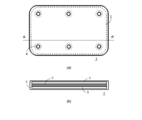
- FIG.1 (a) is a top view from the plate
- FIG.1 (b) is FIG. It is sectional drawing in AA 'of a).
- the method for manufacturing a composite according to the present embodiment includes a porous silicon carbide ceramic sintered body in a method for manufacturing a composite in which a metal is impregnated while a fibrous inorganic material is disposed adjacent to a flat porous inorganic structure.
- a first phase in which a porous silicon carbide ceramic sintered body is impregnated with metal and a second phase in which a fibrous inorganic material is impregnated with metal Is a composite having a structure in which the two are adjacent to each other, the ratio of the porous silicon carbide ceramic sintered body in the first phase is 50 to 80% by volume, and the fibrous inorganic material in the second phase The ratio is 3 to 20% by volume.
- porous silicon carbide ceramic sintered body constituting the porous inorganic structure has pores that can be impregnated with metal, and is not easily deformed or broken during the impregnation operation, for example, a mechanical strength of about 10 MPa. And various porous silicon carbide ceramic sintered bodies having
- a well-known method is employable. For example, it can be obtained by adding silica, alumina or the like as a binder to a raw material silicon carbide (SiC) powder, mixing, molding, and firing at 800 ° C. or higher.
- SiC silicon carbide
- the important characteristics of the first phase in which a porous inorganic structure is impregnated with metal are thermal conductivity and thermal expansion coefficient.
- Higher silicon carbide content in the porous inorganic structure is preferable because of high thermal conductivity and a low thermal expansion coefficient.
- the aluminum alloy may not be sufficiently impregnated. is there.
- the average particle diameter is preferably 40% by mass or more of coarse silicon carbide powder having an average particle diameter of 40 ⁇ m or more, and the relative density of the porous inorganic structure is preferably in the range of 55 to 75%. .
- the strength of the porous inorganic structure is preferably 3 MPa or more in terms of bending strength in order to prevent cracking during handling and during impregnation.
- the average particle diameter is the average value of the diameters obtained for 1000 particles using a scanning electron microscope (for example, “JSM-T200 type” manufactured by JEOL Ltd.) and an image analyzer (for example, manufactured by Nippon Avionics Co., Ltd.). It can be measured by calculating.
- the relative density can be measured by Archimedes method or the like.
- the bending strength can be measured with a tensile tester (for example, manufactured by Shimadzu Corporation).
- the silicon carbide powder is preferably adjusted in particle size.
- a mixed powder obtained by mixing 40 to 80% by mass of coarse powder having an average particle diameter of preferably 40 to 150 ⁇ m and 60 to 20% by mass of fine powder having an average particle diameter of preferably 5 to 15 ⁇ m is suitable.
- the porous silicon carbide ceramic sintered body is obtained by degreasing and firing a formed body of a mixture obtained by adding a binder to silicon carbide powder.
- the firing temperature is 800 ° C. or higher, a sintered body having a bending strength of 3 MPa or more can be obtained regardless of the firing atmosphere.
- firing at a temperature exceeding 1100 ° C. promotes oxidation of silicon carbide, which may reduce the thermal conductivity of the aluminum-silicon carbide composite, so in an oxidizing atmosphere, Baking is preferably performed at a temperature of 1100 ° C. or lower.
- the firing time is appropriately determined in accordance with conditions such as the size of the sintered body, the amount charged into the firing furnace, and the firing atmosphere.
- the porous inorganic structure of this embodiment has an open pore that can be impregnated with a metal or an alloy, and has a mechanical strength that does not break in the impregnation operation. Any material can be used as long as it is a ligature.
- the fibrous inorganic material is disposed adjacent to the flat porous inorganic structure obtained by the above method.
- fibrous alumina is preferable.
- a crystalline alumina fiber having an alumina content of 70% or more is particularly preferable because of good affinity with the metal to be impregnated. Alumina fibers are cheap and easy to obtain.
- the fibrous inorganic material does not require any mechanical strength and may be in any state such as a blanket or a mat.
- the porous inorganic structure made of a porous silicon carbide ceramic sintered body and the metal impregnated into the fibrous inorganic material may be anything as long as the object of the present embodiment can be achieved.
- a light alloy such as aluminum or magnesium or an alloy thereof is preferable.
- the alloy There is no particular limitation on the alloy, and a general-purpose aluminum alloy or magnesium alloy can be used.
- aluminum alloys for casting such as 1000 series, 2000 series, 3000 series, 4000 series, 5000 series, 6000 series, and 7000 series.
- the aluminum-silicon carbide composite using aluminum or an aluminum-based alloy as the metal and silicon carbide as the porous inorganic structure is light in weight, has high thermal conductivity, and heats from the ceramic substrate. This combination is particularly excellent in terms of expansion compatibility.
- various conventionally known impregnation methods can be applied as the metal impregnation method.
- a method by pressure casting is used. desirable. That is, in the case of the die casting method, the mold cavity is made larger than the preform by the surface layer, and the fibrous inorganic material is placed in a space other than the cavity preform to impregnate the metal.
- the composite having the second phase on the surface can be easily produced.
- the front and back surfaces and / or side surfaces of the porous inorganic structure are sandwiched between fibrous inorganic materials, or impregnated with metal in a state of covering the entire surface, or the inner surface of the mold is fibrous. It can be easily manufactured by disposing an inorganic material and impregnating with a metal.
- the fibrous inorganic material may be installed adjacent to the porous inorganic structure. “Adjacent” means a state in which the porous inorganic structure and the fibrous inorganic material are adjacent and in direct contact with each other.
- the fibrous inorganic material can be installed adjacent to the front and back surfaces and / or the side surfaces of the porous inorganic structure. When the fibrous inorganic material covers the entire surface of the porous inorganic structure (that is, the front and back surfaces and side surfaces), a second phase rich in machinability exists on the surface of the resulting composite. ,preferable.
- the proportion of the porous silicon carbide ceramic sintered body in the first phase is preferably 50 to 80% by volume.
- the proportion of the fibrous inorganic material in the second phase is preferably 3 to 20% by volume.
- Such a configuration has a porosity of 20 to 50% by volume of the porous silicon carbide ceramic sintered body in the first phase, and the second It can be produced by setting the porosity of the fibrous inorganic material in the phase to 80 to 97% by volume.
- the porosity can be obtained by calculation from the difference between the theoretical density and the relative density (measured by Archimedes method). Further, the method for adjusting the porosity is not particularly limited.
- the porosity of the fibrous inorganic material can be adjusted by compressing or loosening the felt-like fibrous inorganic material.
- the porosity of the porous silicon carbide ceramic sintered body can be adjusted by the particle size blend of the silicon carbide powder used, the amount of binder added, and the like.
- the second part having a shape protruding partly in a fin shape.
- a conventionally known metal processing method it is not limited to the machining method illustrated by the said surface grinding method and a drilling method, but means all the methods applicable to metal processing.
- the thickness of the layer composed of the second phase depends on the metal processing method selected, the dimensional accuracy of the composite after processing, etc. It may be at least 0.5 ⁇ m or more.
- the thickness of the layer made of the second phase is preferably 50 ⁇ m or more, and more preferably 1 mm or more.
- the upper limit is not particularly limited, but when it exceeds 20 mm, for example, when used as a heat dissipating part of a circuit board for mounting a semiconductor, the composite has a high thermal conductivity and a low coefficient of thermal expansion. May not be able to demonstrate.
- the thickness of the layer composed of the second phase is preferably 20 mm or less.
- the second phase 3 in which the fibrous inorganic material is impregnated with the metal are adjacent to each other, and the ratio of the porous silicon carbide ceramic sintered body in the first phase 2 is 50 to 80 It is possible to obtain a composite 1 characterized in that the proportion of the fibrous inorganic material in the second phase 3 is 3 to 20% by volume.
- the first phase 2 and the second phase 3 are continuously connected to each other by the same metal, so that the porous inorganic structure and the fibrous inorganic material adjacent to each other are formed. This has the effect of preventing peeling and the like from occurring at the interface.
- a through-hole 4 that penetrates the front and back plate surfaces of the flat composite 1 is provided. It is preferable that the first phase 2 is not formed around the through hole 4 from the viewpoint of workability when forming the through hole 4.
- a notch is provided in advance around the portion where the through hole 4 is formed, or a through hole having a larger diameter than the through hole 4 is formed. What is necessary is just to provide a hole.
- the metal layer 5 is formed so as to cover the entire periphery of the first phase 2 and the second phase 3.
- the metal layer 5 may be provided only on the front and back plate surfaces of the composite.
- the composite according to the above embodiment can be applied, for example, as a heat-resistant material such as an abrasion resistant material for a piston part of an automobile or a heat sink.
- Example 1 Silica sol (Nissan Chemical Industry Co., Ltd .: Snowtex) as a binder was added to silicon carbide having an average particle size of 30 ⁇ m (manufactured by Yakushima Electric Works: GS-500S) at a solid concentration of 5% by mass, mixed, and press molded. Then, it baked at 900 degreeC in the air for 2 hours, and produced the porous silicon carbide structure with a porosity of 40% and a magnitude
- Each of the 10 porous silicon carbide structures is sandwiched between two 10 mm thick alumina felts (manufactured by Denki Kagaku Kogyo Co., Ltd., Arsenfeld porosity 90%) and placed in a mold having an inner diameter of 200 mm. Then, an aluminum alloy containing 12% by mass of Si and 1% by mass of Mg melted at 800 ° C. was poured into the mold, and pressed with a push rod at a pressure of 100 MPa to prepare a composite. After cooling, the complex was cut out.
- the thickness of the second phase (a phase in which an aluminum felt was impregnated with an aluminum alloy) was 2 mm. The damaged state was visually observed, but no abnormality was observed.
- the proportion of the porous silicon carbide ceramic sintered body in the first phase was 60% by volume
- the proportion of the fibrous inorganic material in the second phase was 10% by volume
- Example 2 6 silicon carbide with an average particle size of 220 ⁇ m (manufactured by Taiyo Random Co., Ltd .: NG-F80), 16 ⁇ m (manufactured by Yakushima Electric Works: GC # 750), 0.8 ⁇ m (manufactured by Taihei Random Co., Ltd., NG-4S) : Blended at a ratio of 3: 1, 5% by mass of silica sol (manufactured by NISSAN CHEMICAL INDUSTRY CO., LTD .: Snowtex) as a binder was added at a solid concentration, mixed, press-molded, and then in air at 900 ° C. for 2 hours. Firing was performed to produce a porous silicon carbide structure having a porosity of 25% and a size of 100 mm ⁇ 100 mm ⁇ 3 mm.
- the 10 porous silicon carbide structures described above were sandwiched between 2 pieces of alumina felt (thickness 10 mm) made by Denki Kagaku Kogyo Co., Ltd. to loosen the Arsen felt (porosity 90%) to a porosity of 94%.
- the aluminum alloy containing 12% by mass of Si and 1% by mass of Mg melted at 800 ° C. was poured into a mold having an inner diameter of 200 mm, and pressed at a pressure of 100 MPa with a push rod to form a composite. The body was made. After cooling, the complex was cut out.
- the thickness of the second phase (a phase in which an aluminum alloy was impregnated with an alumina felt) was 1.5 mm. The damaged state was visually observed, but no abnormality was observed.
- the ratio of the porous silicon carbide ceramic sintered body in the first phase was 75% by volume, and the ratio of the fibrous inorganic material in the second phase was 6% by volume.
- Example 3 An average particle size of 100 ⁇ m (manufactured by Taihei Random Co., Ltd., NG-F150), 11 ⁇ m (manufactured by Yakushima Electric Works Co., Ltd., GC-1000F), silicon carbide is blended at a ratio of 7: 3, and silica sol (Nissan Chemical Industries Co., Ltd.) as a binder (Made by company: Snowtex) was added at 5% by mass in solid concentration, mixed, press-molded, fired in air at 900 ° C. for 2 hours, porosity of 45%, porosity of 100 mm ⁇ 100 mm ⁇ 3 mm A quality silicon carbide structure was produced.
- the ratio of the porous silicon carbide ceramic sintered body in the first phase was 55% by volume
- the ratio of the fibrous inorganic material in the second phase was 18% by volume.
- Example 1 Except not using an alumina felt, the same operation as in Example 1 was performed, and the obtained 10 composites were observed for the presence or absence of abnormality.
- Example 2 Except for setting the porosity of the alumina felt to 75%, the same operation as in Example 3 was performed, and the obtained 10 composites were observed for abnormality. Three unimpregnated pieces were observed. The thickness of the second phase (a phase in which an aluminum alloy was impregnated with an alumina felt) was 5 mm.
- the proportion of the porous silicon carbide ceramic sintered body in the first phase was 55% by volume
- the proportion of the fibrous inorganic material in the second phase was 25% by volume
- Table 1 shows a summary of Examples 1 to 3 and Comparative Examples 1 to 5 described above.
- the porous silicon carbide structure may be cracked or cracked, or there may be a portion that is not impregnated with metal. Absent.
- damage to the porous inorganic structure contained in the composite is suppressed, and the composite is produced stably. be able to.
Landscapes
- Chemical & Material Sciences (AREA)
- Engineering & Computer Science (AREA)
- Ceramic Engineering (AREA)
- Organic Chemistry (AREA)
- Materials Engineering (AREA)
- Mechanical Engineering (AREA)
- Structural Engineering (AREA)
- Metallurgy (AREA)
- Manufacture Of Alloys Or Alloy Compounds (AREA)
- Ceramic Products (AREA)
- Physics & Mathematics (AREA)
- Plasma & Fusion (AREA)
- Manufacturing & Machinery (AREA)
- Inorganic Chemistry (AREA)
- Civil Engineering (AREA)
Abstract
Description
溶融金属を含浸させる方法としては、粉末冶金法に基づく方法、例えば、ダイキャスト法(特許文献1)や溶湯鍛造法(非特許文献1)等の圧力鋳造による方法、自発浸透による方法(特許文献2)等といった各種の方法が知られている。
本実施形態の複合体の製造方法は、平板状の多孔質無機構造体に繊維状無機材料を隣接配置しながら金属を含浸させる複合体の製造方法において、多孔質炭化珪素セラミックス焼結体からなる多孔質無機構造体、及び繊維状無機材料を用いることにより、多孔質炭化珪素セラミックス焼結体に金属が含浸されている第1相と、繊維状無機材料に金属が含浸されている第2相とが互いに隣接している構造を有する複合体であり、第1相中に占める多孔質炭化珪素セラミックス焼結体の割合が50~80体積%であり、第2相中に占める繊維状無機材料の割合が3~20体積%であることを特徴とする。
構造体の成形方法についても、特に制限は無く、プレス成形、押し出し成形、鋳込み成形等を用いることができ、必要に応じて保形用バインダーの併用が可能である。
実用的には、平均粒子径が、好ましくは40μm以上の粗い炭化珪素粉末を40質量%以上含み、多孔質無機構造体の相対密度が好ましくは55~75%の範囲にあるものが好適である。多孔質無機構造体の強度は、取り扱い時や含浸中の割れを防ぐため、曲げ強度で3MPa以上あることが好ましい。なお、平均粒子径は、走査型電子顕微鏡(例えば日本電子社製「JSM-T200型」)と画像解析装置(例えば日本アビオニクス社製)を用い、1000個の粒子について求めた径の平均値を算出することによって測定することができる。また、相対密度は、アルキメデス法等によって測定することができる。曲げ強度は、引張試験機(例えば島津製作所社製)によって測定することができる。
酸化性雰囲気中では、1100℃を超える温度で焼成すると、炭化珪素の酸化が促進され、アルミニウム-炭化珪素質複合体の熱伝導率が低下してしまう場合があるので、酸化性雰囲気中では、1100℃以下の温度で焼成することが好ましい。焼成時間は、焼結体の大きさ、焼成炉への投入量、焼成雰囲気等の条件に合わせて適宜決められる。
この様な構成は、第1相中に占める多孔質炭化珪素セラミックス焼結体の気孔率を20~50体積%、また第2相中に占める繊維状無機材料の気孔率を80~97体積%とすることで作製することができる。
ここで、従来公知の金属加工法としては、前記の平面研削方法、穴あけ加工方法に例示される機械加工法に限定されるものでなく、金属の加工に適用できるあらゆる方法をいう。
金属加工法のうち安価で生産性の高い汎用の機械加工法を適用する場合には、前記第2相からなる層の厚みとしては50μm以上が好ましく、1mm以上であることが一層好ましい。尚、その上限値に関しては、特に限定するべき理由がないが、20mmを越えるときには、例えば、半導体搭載用回路基板の放熱部品として用いるときに、高熱伝導、低熱膨張率であるという複合体の特徴を発揮することが出来ないおそれがある。また、第1相と第2相の熱膨張率の著しい違いにより、複合体の平面度の保持も難しくなる。よって、第2相からなる層の厚みは、好ましくは20mm以下である。
上記の実施形態の複合体の製造方法によれば、図1に示すような、平板状の多孔質炭化珪素セラミックス焼結体からなる多孔質無機構造体に金属が含浸されている第1相2と、繊維状無機材料に金属が含浸されている第2相3とが互いに隣接している構造を有し、第1相2中に占める多孔質炭化珪素セラミックス焼結体の割合が50~80体積%であり、第2相3中に占める繊維状無機材料の割合が3~20体積%であることを特徴とする複合体1を得ることができる。
〔実施例1〕
平均粒径30μmの炭化珪素(屋久島電工社製:GS-500S)に、バインダーとしてシリカゾル(日産化学工業株式会社製:スノーテックス)を固形分濃度で5質量%添加し、混合し、プレス成形した後、空気中900℃で2時間焼成し、気孔率40%で、大きさ100mm×100mm×3mmの多孔質炭化珪素構造体を作製した。
冷却後、複合体を切り出した。ここで、第2相(アルミナ質のフェルトにアルミニウム合金が含浸された相)の厚みは2mmであった。破損状態を目視にて観察したが、何ら異常を認めなかった。
平均粒径220μm(大平洋ランダム株式会社製:NG-F80)、16μm(屋久島電工株式会社製:GC#750)、0.8μm(大平洋ランダム株式会社製、NG-4S)の炭化珪素を6:3:1の割合でブレンドし、バインダーとしてシリカゾル(日産化学工業株式会社製:スノーテックス)を固形分濃度で5質量%添加し、混合し、プレス成形した後、空気中900℃で2時間焼成し、気孔率25%で、大きさ100mm×100mm×3mmの多孔質炭化珪素構造体を作製した。
冷却後、複合体を切り出した。第2相(アルミナ質のフェルトにアルミニウム合金が含浸された相)の厚みは1.5mmであった。破損状態を目視にて観察したが、何ら異常を認めなかった。
平均粒径100μm(大平洋ランダム株式会社製、NG-F150)、11μm(屋久島電工株式会社製、GC-1000F)、炭化珪素を7:3の割合でブレンドし、バインダーとしてシリカゾル(日産化学工業株式会社製:スノーテックス)を固形分濃度で5質量%添加し、混合し、プレス成形した後、空気中900℃で2時間焼成し、気孔率45%で、大きさ100mm×100mm×3mmの多孔質炭化珪素構造体を作製した。
アルミナ質のフェルトを用いないこと以外は、実施例1と同じ操作を行い、得られた10個の複合体について、異常の有無を観察した。超音波探傷試験機にて複合体内部の多孔質炭化珪素構造体が短手方向全幅で割れているものが1個、外観目視にて複合体に3~10mm程度のクラックが認められたものが4個であった。なお、この場合の第1相中に占める多孔質炭化珪素セラミックス焼結体の割合は60体積%であった。
アルミナ質のフェルトの気孔率を75%とした以外は、実施例3と同じ操作を行い、得られた10個の複合体について、異常の有無を観察したところ、アルミナ質フェルト部にアルミニウム合金の未含浸が3個認められた。第2相(アルミナ質のフェルトにアルミニウム合金が含浸された相)の厚みは5mmであった。
実施例2と同様の操作にて気孔率15%の多孔質炭化珪素構造体を得ようとしたが作製不可であった。なお、ここで想定した第1相中に占める多孔質炭化珪素セラミックス焼結体の割合は85体積%であった。
実施例2と同様の操作にて気孔率60%の多孔質炭化珪素構造体を得ようとしたが作製不可であった。なお、ここで想定した第1相中に占める多孔質炭化珪素セラミックス焼結体の割合は40体積%であった。
アルミナ質のフェルトの気孔率をアルセンフェルト(気孔率90%)をほぐして気孔率98%とした以外は、実施例1と同じ操作を行い、得られた10個の複合体について、異常の有無を観察したところ、外観目視にて3~10mm程度のクラックが認められたものが4個であった。第2相(アルミナ質のフェルトにアルミニウム合金が含浸された相)の厚みは1mmであった。なお、この場合の第1相中に占める多孔質炭化珪素セラミックス焼結体の割合は60体積%であり、第2相中に占める繊維状無機材料の割合は2体積%であった。

2 第1相
3 第2相
4 貫通孔
5 金属層
Claims (9)
- 平板状の多孔質無機構造体に繊維状無機材料を隣接配置しながら金属を含浸させる複合体の製造方法において、
多孔質炭化珪素セラミックス焼結体からなる多孔質無機構造体、及び繊維状無機材料を用いることにより、多孔質炭化珪素セラミックス焼結体に金属が含浸されている第1相と、繊維状無機材料に金属が含浸されている第2相とが互いに隣接している構造を有する複合体であり、
第1相中に占める多孔質炭化珪素セラミックス焼結体の割合が50~80体積%であり、
第2相中に占める繊維状無機材料の割合が3~20体積%であることを特徴とする複合体の製造方法。 - 金属を含浸させる方法がダイキャスト法又は溶湯鍛造法であることを特徴とする請求項1に記載の複合体の製造方法。
- 前記金属がアルミニウム又はアルミニウム合金であることを特徴とする請求項1又は2に記載の複合体の製造方法。
- 前記第2相からなる層の厚みが1mm以上であることを特徴とする請求項1から3のいずれか一項に記載の複合体の製造方法。
- 繊維状無機材料が多孔質炭化珪素セラミックス焼結体の周囲全面を覆う状態とするか、又は、多孔質炭化珪素セラミックス焼結体を繊維状無機材料2枚で挟む状態とすることを特徴とする請求項1から4のいずれか一項に記載の複合体の製造方法。
- 平板状の多孔質炭化珪素セラミックス焼結体からなる多孔質無機構造体に金属が含浸されている第1相と、繊維状無機材料に金属が含浸されている第2相とが互いに隣接している構造を有し、
第1相中に占める多孔質炭化珪素セラミックス焼結体の割合が50~80体積%であり、
第2相中に占める繊維状無機材料の割合が3~20体積%であることを特徴とする複合体。 - 前記金属がアルミニウム又はアルミニウム合金であることを特徴とする請求項6に記載の複合体。
- 前記第2相からなる層の厚みが1mm以上であることを特徴とする請求項6又は7に記載の複合体。
- 前記第2相が前記第1相の周囲全面を覆う状態であるか、又は、前記第2相の表裏板面のみに前記第1相が形成された状態であることを特徴とする請求項6から8のいずれか一項に記載の複合体。
Priority Applications (3)
| Application Number | Priority Date | Filing Date | Title |
|---|---|---|---|
| CN201580051561.7A CN106715004B (zh) | 2014-07-24 | 2015-07-24 | 复合体及其制造方法 |
| JP2016535986A JP6839981B2 (ja) | 2014-07-24 | 2015-07-24 | 複合体及びその製造方法 |
| US15/328,723 US10081055B2 (en) | 2014-07-24 | 2015-07-24 | Composite body and method for producing same |
Applications Claiming Priority (2)
| Application Number | Priority Date | Filing Date | Title |
|---|---|---|---|
| JP2014-151148 | 2014-07-24 | ||
| JP2014151148 | 2014-07-24 |
Publications (1)
| Publication Number | Publication Date |
|---|---|
| WO2016013648A1 true WO2016013648A1 (ja) | 2016-01-28 |
Family
ID=55163171
Family Applications (1)
| Application Number | Title | Priority Date | Filing Date |
|---|---|---|---|
| PCT/JP2015/071082 Ceased WO2016013648A1 (ja) | 2014-07-24 | 2015-07-24 | 複合体及びその製造方法 |
Country Status (4)
| Country | Link |
|---|---|
| US (1) | US10081055B2 (ja) |
| JP (2) | JP6839981B2 (ja) |
| CN (1) | CN106715004B (ja) |
| WO (1) | WO2016013648A1 (ja) |
Cited By (2)
| Publication number | Priority date | Publication date | Assignee | Title |
|---|---|---|---|---|
| WO2020145365A1 (ja) * | 2019-01-10 | 2020-07-16 | 日本碍子株式会社 | 放熱部材 |
| CN113334867A (zh) * | 2021-05-18 | 2021-09-03 | 中国石油大学(北京) | 一种金属泡沫复合材料及其制备方法 |
Families Citing this family (3)
| Publication number | Priority date | Publication date | Assignee | Title |
|---|---|---|---|---|
| CN110430716A (zh) * | 2019-06-30 | 2019-11-08 | 西南电子技术研究所(中国电子科技集团公司第十研究所) | 高效均热板的制备方法 |
| WO2022075288A1 (ja) * | 2020-10-09 | 2022-04-14 | Agc株式会社 | SiSiC部材および加熱器具 |
| TWI908087B (zh) * | 2024-05-22 | 2025-12-11 | 世銓科技股份有限公司 | 一種熱擴散器件的製造方法 |
Citations (6)
| Publication number | Priority date | Publication date | Assignee | Title |
|---|---|---|---|---|
| JPH11269575A (ja) * | 1998-03-23 | 1999-10-05 | Denki Kagaku Kogyo Kk | 複合体とそれを用いたヒートシンク |
| JPH11277217A (ja) * | 1998-01-19 | 1999-10-12 | Mitsubishi Materials Corp | 放熱用基板およびその製造方法 |
| JP2003204022A (ja) * | 2002-01-10 | 2003-07-18 | Denki Kagaku Kogyo Kk | 放熱部品 |
| WO2007080701A1 (ja) * | 2006-01-13 | 2007-07-19 | Denki Kagaku Kogyo Kabushiki Kaisha | アルミニウム-炭化珪素質複合体及びそれを用いた放熱部品 |
| WO2007125878A1 (ja) * | 2006-04-26 | 2007-11-08 | Denki Kagaku Kogyo Kabushiki Kaisha | アルミニウム-炭化珪素質複合体及びそれを用いた放熱部品 |
| JP2010024077A (ja) * | 2008-07-17 | 2010-02-04 | Denki Kagaku Kogyo Kk | アルミニウム−炭化珪素質複合体及びその製造方法 |
Family Cites Families (18)
| Publication number | Priority date | Publication date | Assignee | Title |
|---|---|---|---|---|
| US4998578A (en) | 1988-01-11 | 1991-03-12 | Lanxide Technology Company, Lp | Method of making metal matrix composites |
| US4871008A (en) | 1988-01-11 | 1989-10-03 | Lanxide Technology Company, Lp | Method of making metal matrix composites |
| US5119864A (en) | 1988-11-10 | 1992-06-09 | Lanxide Technology Company, Lp | Method of forming a metal matrix composite through the use of a gating means |
| US5259436A (en) | 1991-04-08 | 1993-11-09 | Aluminum Company Of America | Fabrication of metal matrix composites by vacuum die casting |
| EP0519641A1 (en) * | 1991-06-17 | 1992-12-23 | General Electric Company | Silicon carbide composite with coated fiber reinforcement and method of forming |
| US6107225A (en) * | 1997-10-23 | 2000-08-22 | Agency Of Industrial Science And Technology | High-temperature ceramics-based composite material and its manufacturing process |
| JP3813007B2 (ja) * | 1997-11-07 | 2006-08-23 | 電気化学工業株式会社 | 複合体とそれを用いたヒートシンク、及び複合体の製造方法 |
| JP4080053B2 (ja) * | 1998-03-23 | 2008-04-23 | 電気化学工業株式会社 | 複合体の製造方法 |
| JP3468358B2 (ja) | 1998-11-12 | 2003-11-17 | 電気化学工業株式会社 | 炭化珪素質複合体及びその製造方法とそれを用いた放熱部品 |
| JP3775088B2 (ja) * | 1999-01-18 | 2006-05-17 | いすゞ自動車株式会社 | シリンダブロックの製造方法 |
| JP3496816B2 (ja) * | 1999-06-25 | 2004-02-16 | 電気化学工業株式会社 | 金属−セラミックス複合体とそれを用いた放熱部品 |
| DE10131758A1 (de) * | 2001-06-30 | 2003-01-16 | Sgl Carbon Ag | Faserverstärkter, wenigstens im Randbereich aus einer Metall-Verbundkeramik bestehender Werkstoff |
| JP4761157B2 (ja) * | 2004-09-14 | 2011-08-31 | 電気化学工業株式会社 | アルミニウム−炭化珪素質複合体 |
| US20090075056A1 (en) * | 2006-05-09 | 2009-03-19 | Denki Kagaku Kogyo Kabushiki Kaisha | Aluminum-silicon carbide composite body and method for processing the same |
| EP2325153B8 (en) * | 2008-07-17 | 2015-04-08 | Denki Kagaku Kogyo Kabushiki Kaisha | Manufacturing method of aluminium-diamond composite |
| WO2010092972A1 (ja) * | 2009-02-13 | 2010-08-19 | 電気化学工業株式会社 | Led発光素子用複合材料基板、その製造方法及びled発光素子 |
| US20130323589A1 (en) * | 2011-02-10 | 2013-12-05 | Showa Denko K.K. | Current collector |
| JP6704847B2 (ja) | 2014-03-18 | 2020-06-03 | デンカ株式会社 | アルミニウム−炭化珪素質複合体及びパワーモジュール用ベース板 |
-
2015
- 2015-07-24 JP JP2016535986A patent/JP6839981B2/ja active Active
- 2015-07-24 WO PCT/JP2015/071082 patent/WO2016013648A1/ja not_active Ceased
- 2015-07-24 CN CN201580051561.7A patent/CN106715004B/zh active Active
- 2015-07-24 US US15/328,723 patent/US10081055B2/en active Active
-
2020
- 2020-12-21 JP JP2020211772A patent/JP7160888B2/ja active Active
Patent Citations (6)
| Publication number | Priority date | Publication date | Assignee | Title |
|---|---|---|---|---|
| JPH11277217A (ja) * | 1998-01-19 | 1999-10-12 | Mitsubishi Materials Corp | 放熱用基板およびその製造方法 |
| JPH11269575A (ja) * | 1998-03-23 | 1999-10-05 | Denki Kagaku Kogyo Kk | 複合体とそれを用いたヒートシンク |
| JP2003204022A (ja) * | 2002-01-10 | 2003-07-18 | Denki Kagaku Kogyo Kk | 放熱部品 |
| WO2007080701A1 (ja) * | 2006-01-13 | 2007-07-19 | Denki Kagaku Kogyo Kabushiki Kaisha | アルミニウム-炭化珪素質複合体及びそれを用いた放熱部品 |
| WO2007125878A1 (ja) * | 2006-04-26 | 2007-11-08 | Denki Kagaku Kogyo Kabushiki Kaisha | アルミニウム-炭化珪素質複合体及びそれを用いた放熱部品 |
| JP2010024077A (ja) * | 2008-07-17 | 2010-02-04 | Denki Kagaku Kogyo Kk | アルミニウム−炭化珪素質複合体及びその製造方法 |
Cited By (4)
| Publication number | Priority date | Publication date | Assignee | Title |
|---|---|---|---|---|
| WO2020145365A1 (ja) * | 2019-01-10 | 2020-07-16 | 日本碍子株式会社 | 放熱部材 |
| JPWO2020145365A1 (ja) * | 2019-01-10 | 2021-11-25 | 日本碍子株式会社 | 放熱部材 |
| JP7431176B2 (ja) | 2019-01-10 | 2024-02-14 | 日本碍子株式会社 | 放熱部材 |
| CN113334867A (zh) * | 2021-05-18 | 2021-09-03 | 中国石油大学(北京) | 一种金属泡沫复合材料及其制备方法 |
Also Published As
| Publication number | Publication date |
|---|---|
| JP2021087995A (ja) | 2021-06-10 |
| CN106715004B (zh) | 2019-09-24 |
| US20170239715A1 (en) | 2017-08-24 |
| JP7160888B2 (ja) | 2022-10-25 |
| US10081055B2 (en) | 2018-09-25 |
| JP6839981B2 (ja) | 2021-03-10 |
| CN106715004A (zh) | 2017-05-24 |
| JPWO2016013648A1 (ja) | 2017-05-25 |
Similar Documents
| Publication | Publication Date | Title |
|---|---|---|
| JP7160888B2 (ja) | 複合体及びその製造方法 | |
| JP4761157B2 (ja) | アルミニウム−炭化珪素質複合体 | |
| JP7427647B2 (ja) | 放熱部材 | |
| US6383656B1 (en) | Perform for metal matrix composite material and cylinder block made of the same | |
| JPWO2017065139A1 (ja) | アルミニウム−ダイヤモンド系複合体及びその製造方法 | |
| JP5464301B2 (ja) | 放熱基板用複合材料の製造方法 | |
| JP6636924B2 (ja) | アルミニウム‐炭化珪素質複合体及びその製造方法 | |
| US10869413B2 (en) | Heat-dissipating component and method for manufacturing same | |
| WO2020158774A1 (ja) | 放熱部材およびその製造方法 | |
| RU2009120387A (ru) | Способ изготовления изделия из металлокерамических композиционных материалов | |
| KR102660216B1 (ko) | 치밀질 복합 재료, 그 제법, 접합체 및 반도체 제조 장치용 부재 | |
| JP4080053B2 (ja) | 複合体の製造方法 | |
| WO2023058597A1 (ja) | 放熱部材 | |
| JP2020123713A (ja) | 放熱部材およびその製造方法 | |
| WO2017122564A1 (ja) | 内燃機関用ピストンおよび内燃機関用ピストンの製造方法 | |
| JP2023055311A (ja) | 放熱部材の製造方法 | |
| JP2025183379A (ja) | 放熱部材 | |
| JP2009154181A (ja) | 複合部材およびその製造方法 | |
| JP2011225910A (ja) | セラミック粒子強化金属複合材の作製方法 |
Legal Events
| Date | Code | Title | Description |
|---|---|---|---|
| 121 | Ep: the epo has been informed by wipo that ep was designated in this application |
Ref document number: 15824737 Country of ref document: EP Kind code of ref document: A1 |
|
| ENP | Entry into the national phase |
Ref document number: 2016535986 Country of ref document: JP Kind code of ref document: A |
|
| NENP | Non-entry into the national phase |
Ref country code: DE |
|
| WWE | Wipo information: entry into national phase |
Ref document number: 15328723 Country of ref document: US |
|
| 122 | Ep: pct application non-entry in european phase |
Ref document number: 15824737 Country of ref document: EP Kind code of ref document: A1 |