WO2016006443A1 - 信号処理装置、サスペンション制御装置および信号処理方法 - Google Patents
信号処理装置、サスペンション制御装置および信号処理方法 Download PDFInfo
- Publication number
- WO2016006443A1 WO2016006443A1 PCT/JP2015/068165 JP2015068165W WO2016006443A1 WO 2016006443 A1 WO2016006443 A1 WO 2016006443A1 JP 2015068165 W JP2015068165 W JP 2015068165W WO 2016006443 A1 WO2016006443 A1 WO 2016006443A1
- Authority
- WO
- WIPO (PCT)
- Prior art keywords
- calculation unit
- signal processing
- damper speed
- characteristic
- low
- Prior art date
- Legal status (The legal status is an assumption and is not a legal conclusion. Google has not performed a legal analysis and makes no representation as to the accuracy of the status listed.)
- Ceased
Links
Images
















Classifications
-
- B—PERFORMING OPERATIONS; TRANSPORTING
- B60—VEHICLES IN GENERAL
- B60G—VEHICLE SUSPENSION ARRANGEMENTS
- B60G17/00—Resilient suspensions having means for adjusting the spring or vibration-damper characteristics, for regulating the distance between a supporting surface and a sprung part of vehicle or for locking suspension during use to meet varying vehicular or surface conditions, e.g. due to speed or load
- B60G17/015—Resilient suspensions having means for adjusting the spring or vibration-damper characteristics, for regulating the distance between a supporting surface and a sprung part of vehicle or for locking suspension during use to meet varying vehicular or surface conditions, e.g. due to speed or load the regulating means comprising electric or electronic elements
- B60G17/018—Resilient suspensions having means for adjusting the spring or vibration-damper characteristics, for regulating the distance between a supporting surface and a sprung part of vehicle or for locking suspension during use to meet varying vehicular or surface conditions, e.g. due to speed or load the regulating means comprising electric or electronic elements characterised by the use of a specific signal treatment or control method
-
- B—PERFORMING OPERATIONS; TRANSPORTING
- B60—VEHICLES IN GENERAL
- B60G—VEHICLE SUSPENSION ARRANGEMENTS
- B60G17/00—Resilient suspensions having means for adjusting the spring or vibration-damper characteristics, for regulating the distance between a supporting surface and a sprung part of vehicle or for locking suspension during use to meet varying vehicular or surface conditions, e.g. due to speed or load
- B60G17/015—Resilient suspensions having means for adjusting the spring or vibration-damper characteristics, for regulating the distance between a supporting surface and a sprung part of vehicle or for locking suspension during use to meet varying vehicular or surface conditions, e.g. due to speed or load the regulating means comprising electric or electronic elements
-
- B—PERFORMING OPERATIONS; TRANSPORTING
- B60—VEHICLES IN GENERAL
- B60G—VEHICLE SUSPENSION ARRANGEMENTS
- B60G17/00—Resilient suspensions having means for adjusting the spring or vibration-damper characteristics, for regulating the distance between a supporting surface and a sprung part of vehicle or for locking suspension during use to meet varying vehicular or surface conditions, e.g. due to speed or load
- B60G17/015—Resilient suspensions having means for adjusting the spring or vibration-damper characteristics, for regulating the distance between a supporting surface and a sprung part of vehicle or for locking suspension during use to meet varying vehicular or surface conditions, e.g. due to speed or load the regulating means comprising electric or electronic elements
- B60G17/016—Resilient suspensions having means for adjusting the spring or vibration-damper characteristics, for regulating the distance between a supporting surface and a sprung part of vehicle or for locking suspension during use to meet varying vehicular or surface conditions, e.g. due to speed or load the regulating means comprising electric or electronic elements characterised by their responsiveness, when the vehicle is travelling, to specific motion, a specific condition, or driver input
- B60G17/0164—Resilient suspensions having means for adjusting the spring or vibration-damper characteristics, for regulating the distance between a supporting surface and a sprung part of vehicle or for locking suspension during use to meet varying vehicular or surface conditions, e.g. due to speed or load the regulating means comprising electric or electronic elements characterised by their responsiveness, when the vehicle is travelling, to specific motion, a specific condition, or driver input mainly during accelerating or braking
-
- B—PERFORMING OPERATIONS; TRANSPORTING
- B60—VEHICLES IN GENERAL
- B60G—VEHICLE SUSPENSION ARRANGEMENTS
- B60G17/00—Resilient suspensions having means for adjusting the spring or vibration-damper characteristics, for regulating the distance between a supporting surface and a sprung part of vehicle or for locking suspension during use to meet varying vehicular or surface conditions, e.g. due to speed or load
- B60G17/015—Resilient suspensions having means for adjusting the spring or vibration-damper characteristics, for regulating the distance between a supporting surface and a sprung part of vehicle or for locking suspension during use to meet varying vehicular or surface conditions, e.g. due to speed or load the regulating means comprising electric or electronic elements
- B60G17/016—Resilient suspensions having means for adjusting the spring or vibration-damper characteristics, for regulating the distance between a supporting surface and a sprung part of vehicle or for locking suspension during use to meet varying vehicular or surface conditions, e.g. due to speed or load the regulating means comprising electric or electronic elements characterised by their responsiveness, when the vehicle is travelling, to specific motion, a specific condition, or driver input
- B60G17/0165—Resilient suspensions having means for adjusting the spring or vibration-damper characteristics, for regulating the distance between a supporting surface and a sprung part of vehicle or for locking suspension during use to meet varying vehicular or surface conditions, e.g. due to speed or load the regulating means comprising electric or electronic elements characterised by their responsiveness, when the vehicle is travelling, to specific motion, a specific condition, or driver input to an external condition, e.g. rough road surface, side wind
-
- B—PERFORMING OPERATIONS; TRANSPORTING
- B60—VEHICLES IN GENERAL
- B60G—VEHICLE SUSPENSION ARRANGEMENTS
- B60G17/00—Resilient suspensions having means for adjusting the spring or vibration-damper characteristics, for regulating the distance between a supporting surface and a sprung part of vehicle or for locking suspension during use to meet varying vehicular or surface conditions, e.g. due to speed or load
- B60G17/06—Characteristics of dampers, e.g. mechanical dampers
-
- B—PERFORMING OPERATIONS; TRANSPORTING
- B60—VEHICLES IN GENERAL
- B60G—VEHICLE SUSPENSION ARRANGEMENTS
- B60G2400/00—Indexing codes relating to detected, measured or calculated conditions or factors
- B60G2400/90—Other conditions or factors
- B60G2400/91—Frequency
Definitions
- the present invention relates to a suspension control device for controlling a suspension of a vehicle, a signal processing device used therefor, and a method thereof.
- the semi-active suspension system which is one of the active suspension systems, uses a shock absorber (damper) with a variable damping force (strictly speaking, a damping characteristic). It is something to control.
- Patent Document 1 a damper speed detected by a damper displacement sensor is passed through a differential filter and time-differentiated to calculate a damper speed, and a target current supplied to the damper by map search using the damper speed is calculated.
- An example of calculation is described.
- a differential filter with a minimum phase delay is designed to ensure control up to the unsprung resonance frequency region, high-frequency noise is generated in the output damper speed signal (for example, paragraph of Patent Document 1). [0004]).
- Patent Document 1 filters a signal of a target current, which is a controlled variable, with a low-pass filter that passes through an unsprung resonance frequency region in order to remove the high-frequency noise.
- a phase delay occurs in the control amount, which causes a problem that the control performance deteriorates.
- an object of the present invention is to provide a suspension control device that suppresses phase delay and has improved control performance, and a signal processing device and a signal processing method used therefor.
- a signal processing apparatus is a signal processing apparatus that reads a suspension displacement and outputs a damper speed, and includes a damper speed calculation unit.
- the damper speed calculation unit is configured to differentiate the suspension displacement using a differential calculation characteristic having a gain characteristic with a slope larger than the slope of the fully differential gain characteristic in the unsprung resonance frequency region.
- the damper speed calculation unit uses a differential calculation characteristic that further has a gain characteristic with a slope smaller than a slope of the gain characteristic of the perfect differential in a frequency range between the sprung resonance frequency range and the unsprung resonance frequency range. Also good. Thereby, in the unsprung resonance frequency region, it can be avoided that the gain becomes larger than the gain of perfect differentiation, that is, the gain of the original damper speed. Further, the phase in the unsprung resonance frequency region can be brought close to the phase of the original damper speed.
- the damper speed calculation unit may use differential calculation characteristics having phase characteristics including a phase that is the same as a fully differential phase in the unsprung resonance frequency region. That is, phase characteristics including the phase of the original damper speed can be obtained in the unsprung resonance frequency region.
- a damper speed from the damper speed calculator may be input, and a low-pass calculator having a cutoff frequency that is variable according to vehicle motion information may be further provided.
- the noise component included in the damper speed can be removed by the low-pass calculation unit.
- the cut-off frequency is variable, it is possible to adaptively divide the scene that prioritizes the output accuracy of the damper speed and the scene that prioritizes noise removal according to the vehicle motion information, improving control performance To do.
- the signal processing device may further include a switching unit that causes the low-pass calculation unit to function and stops the operation based on a cutoff frequency calculated according to the vehicle motion information.
- a switching unit that causes the low-pass calculation unit to function and stops the operation based on a cutoff frequency calculated according to the vehicle motion information.
- the signal processing device may further include a low-pass calculation unit that receives the suspension displacement and has a cutoff frequency that is variable according to vehicle motion information. Then, the suspension displacement subjected to the low-pass calculation by the low-pass calculation unit may be input to the damper speed calculation unit. The noise component included in the damper speed information can be removed by the low-pass calculation unit. Moreover, since the cut-off frequency is variable, according to the vehicle motion information, it is possible to adaptively divide the scene that prioritizes the output accuracy (calculation accuracy) of the damper speed and the scene that prioritizes noise removal, Control performance is improved.
- the signal processing device may further include a calculation unit that calculates an unsprung vibration level as the vehicle motion information.
- the low-pass calculation unit can change the cutoff frequency based on the unsprung vibration level.
- the calculation unit may calculate the unsprung vibration level based on unsprung acceleration. That is, the calculation unit does not calculate the vibration level from the damper speed as described above, but calculates the unsprung vibration level from the unsprung acceleration. Therefore, the unsprung vibration can be reliably detected, and the scene where priority is given to the output accuracy of the damper speed and the scene where priority is given to noise removal can be adaptively divided, and the control performance is improved.
- the calculation unit may include a low-pass filter unit having a cutoff frequency that is variable according to unsprung acceleration.
- the calculation unit may calculate the unsprung vibration level based on the damper speed calculated by the damper speed calculation unit. According to the present invention, since it is not necessary to provide an unsprung acceleration sensor, the cost is not increased.
- the calculation unit may include a low-pass filter unit having a cutoff frequency that is variable according to the damper speed calculated by the damper speed calculation unit.
- the S / N ratio may decrease.
- the unsprung vibration level is likely to fluctuate. This variation may affect the output result of the final damper speed.
- the filter unit of the calculation unit since the filter unit of the calculation unit has a cutoff frequency that is variable according to the damper speed, the fluctuation of the unsprung vibration level is reduced, and the signal processing device has the damper speed with the reduced fluctuation. Finally, it can be output.
- the low-pass calculation unit may calculate the cutoff frequency based on a plurality of types of vehicle motion information. By obtaining a plurality of types of vehicle motion information, the low-pass calculation unit can appropriately output a highly accurate damper speed according to the situation.
- the low-pass calculation unit may calculate a cutoff frequency based on an unsprung vibration level and a damping coefficient corresponding value corresponding to a change in the damping coefficient of the damper.
- the signal processing apparatus can perform calculation using not only the unsprung vibration level but also the damper damping coefficient corresponding to the damping coefficient corresponding value.
- the damper speed can be calculated in a state closer to the actual characteristics, the output accuracy of the damper speed is improved, and the control performance is improved.
- the low-pass calculation unit may calculate one cutoff frequency based on a cutoff frequency calculated based on the unsprung vibration level and a cutoff frequency calculated based on the damping coefficient corresponding value.
- the low-pass calculation unit may include a low selection unit that outputs the one cutoff frequency by a low selection process.
- the low-pass calculation unit may include a multiplication unit that calculates a ratio value based on the damping coefficient corresponding value and multiplies the reference cutoff frequency calculated based on the unsprung vibration level by the ratio value.
- the low-pass calculation unit may include a multiplication unit that calculates a ratio value based on the unsprung vibration level and multiplies the reference cutoff frequency calculated based on the damping coefficient corresponding value by the ratio value.
- the signal processing device uses a plurality of low-pass filters that respectively perform low-pass filter processing on damper speeds from the damper speed calculation unit at a plurality of different cutoff frequencies, and the plurality of low-pass filters according to vehicle motion information. And a switching means for selectively switching between. Thereby, the amount of information processing used for signal processing can be reduced, and control can be simplified.
- the damper speed calculation unit may use a differential calculation characteristic that further has a band elimination filter characteristic in a frequency region higher than the unsprung resonance frequency region. As a result, it is possible to achieve both the compensation of the phase lag of the damper speed in the unsprung resonance frequency region and the removal of high frequency noise, thereby improving the control performance.
- the damper speed calculation unit may use a differential calculation characteristic further including the band elimination filter characteristic in series for each frequency higher than the unsprung resonance frequency region. As a result, the effects of the above-described phase delay compensation and high-frequency noise removal can be promoted.
- the damper speed calculation unit may use a differential calculation characteristic further having a high-pass filter characteristic having a cutoff frequency lower than that of the sprung resonance frequency region.
- the phase characteristic in the sprung resonance frequency region can be brought close to the fully differential phase characteristic. That is, phase characteristics including the phase of the original damper speed can be obtained in the sprung resonance frequency region.
- a suspension control apparatus includes the above-described damper speed calculation unit and a control calculation unit that generates a control command value for controlling the damper based on the damper speed.
- a signal processing method includes reading suspension displacement. Then, in the unsprung resonance frequency region, the read suspension displacement is differentiated using a differential calculation characteristic having a gain characteristic with a slope larger than the slope of the fully differential gain characteristic.
- the phase delay is suppressed and the control performance is improved.
- FIG. 1 is a block diagram showing a suspension control system according to an embodiment of the present invention.
- FIG. 2 is a block diagram illustrating a configuration of the suspension displacement processing unit according to the first embodiment.
- 3A and 3B show Bode diagrams which are differential calculation characteristics of the damper speed calculation unit.
- FIG. 4 is a flowchart illustrating the operation of the suspension displacement processing unit according to the first embodiment.
- FIG. 5 shows another example of the damper speed calculation unit as the configuration of the displacement displacement processing unit according to the second embodiment.
- 6A and 6B show differential calculation characteristics of the damper speed calculation unit shown in FIG.
- FIGS. 7A and 7B show gain characteristics and phase characteristics obtained by comparing the differential operation characteristics of the second embodiment shown in FIGS. 6A and 6B with Comparative Example 1, respectively.
- FIGS. 8A and 8B show an LPF characteristic that passes a low band, a BPF characteristic that passes a middle band, and a low / medium synthesis filter characteristic that is generated by synthesizing these.
- FIGS. 9A and 9B show filter characteristics generated by combining the low-to-medium synthesis filter characteristics of FIGS. 8A and 8B with high-frequency BEF characteristics in series and synthesizing the three areas of low, medium, and high.
- 10A and 10B show a comparison between the differential calculation characteristic having the high frequency BEF characteristic and the differential calculation characteristic having the LPF characteristic according to Comparative Examples 2, 3, and 4.
- 11A and 11B show differential calculation characteristics in the damper speed calculation unit according to the third embodiment.
- FIG. 12 shows differential calculation characteristics in the damper speed calculation unit according to the fourth embodiment.
- FIG. 13 is a block diagram illustrating a configuration of a suspension displacement processing unit according to the fifth embodiment.
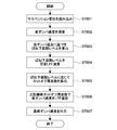
- FIG. 14 is a flowchart showing the operation of the suspension displacement processing unit.
- FIG. 15 is an analysis model for examining the transmission characteristics from the suspension speed to the damper speed.
- 16A and 16B show gain characteristics and phase characteristics that change depending on the magnitude of the damper attenuation coefficient.
- 17A and 17B show characteristics when an LPF having a variable cutoff frequency is connected in series to the differential operation filter of the second embodiment and the cutoff frequency is changed.
- FIG. 18 is a block diagram illustrating a configuration of a suspension displacement processing unit according to the sixth embodiment.
- FIG. 19A is a block diagram showing a configuration of the low-pass calculation unit shown in FIG. FIG.
- FIG. 19B shows an example in which the map is graphed.
- FIG. 19C shows a low-pass calculation unit according to a modification of the sixth embodiment.
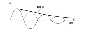
- FIG. 20 conceptually shows the vibration level.
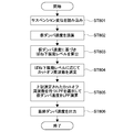
- FIG. 21 is a flowchart illustrating the operation of the suspension displacement processing unit according to the sixth embodiment.
- FIG. 22 is a block diagram illustrating a configuration of a suspension displacement processing unit according to the seventh embodiment.
- FIG. 23 is a block diagram showing a configuration of the unsprung vibration level calculation unit shown in FIG.
- FIG. 24 is a flowchart illustrating the operation of the suspension displacement processing unit according to the seventh embodiment.
- FIG. 25 is a block diagram illustrating a configuration of a suspension displacement processing unit according to the eighth embodiment.
- FIG. 26A is a block diagram showing a configuration of the low-pass calculation unit shown in FIG.
- FIG. 26B shows an example in which the map is graphed.
- FIG. 27 is a flowchart illustrating the operation of the suspension displacement processing unit according to the eighth embodiment.
- 28A to 28C are diagrams for explaining a calculation example by the calculation unit 141 in the low-pass calculation unit of the eighth embodiment.
- FIG. 29 shows an example of the map in FIG. 28B.
- FIG. 30 is a block diagram illustrating a configuration of a suspension displacement processing unit according to the ninth embodiment.
- FIG. 31 is a block diagram showing a configuration of the unsprung vibration level calculation unit shown in FIG.
- FIG. 32 is a flowchart illustrating the operation of the suspension displacement processing unit according to the ninth embodiment.
- FIG. 33 is a block diagram illustrating a configuration of a suspension displacement processing unit according to the tenth embodiment.
- FIG. 34 is a flowchart illustrating the operation of the suspension displacement processing unit according to the tenth embodiment.
- FIG. 35 is a block diagram illustrating a configuration of a suspension displacement processing unit according to the eleventh embodiment.
- FIG. 36 is a flowchart illustrating the operation of the suspension displacement processing unit according to the eleventh embodiment.
- FIG. 37 is a block diagram illustrating a configuration of a suspension displacement processing unit according to the twelfth embodiment.
- FIG. 38 is a flowchart illustrating the operation of the suspension displacement processing unit according to the twelfth embodiment.
- 39A and 39B are block diagrams respectively showing the configuration of the damper speed calculation unit according to the thirteenth embodiment.
- FIG. 1 is a block diagram showing a suspension control system according to an embodiment of the present invention.
- This suspension control system 1 can be typically employed in a four-wheeled vehicle as a vehicle.
- the suspension control system 1 includes a sensor unit 10 including a plurality of sensors, and a suspension control device 20 that controls the movement of a suspension (not shown) based on various detection values from the sensor unit 10.
- the sensor unit 10 includes various sensors that provide information related to the behavior of the vehicle, such as a sprung acceleration sensor 11, a displacement sensor 13, a wheel speed sensor 15, and the like.
- the sprung acceleration sensor 11 is attached to, for example, a vehicle body (for example, a chassis) and detects the sprung acceleration.
- the displacement sensor 13 is also called a vehicle height sensor, and is attached to, for example, a vehicle body or a suspension arm, and detects a relative displacement between them, that is, a relative displacement between an unsprung portion and an unsprung portion. In the following description, this relative displacement between the sprung and unsprung portions is referred to as suspension displacement.
- the wheel speed sensor 15 detects the wheel speed and is attached to, for example, a wheel hub.
- the sensor unit 10 may include an unsprung acceleration sensor, a rudder angle sensor, and the like in addition to the unsprung acceleration sensor 11, the displacement sensor 13, and the wheel speed sensor 15.
- the displacement sensor 13 may be provided on only two of the four wheels, or the sprung acceleration sensor 11 may be singular or plural.
- not all the above sensors are mounted on one vehicle.
- one of the unsprung acceleration sensor and the displacement sensor 13 is often mounted on one vehicle.
- a suspension control system including a displacement sensor 13 without an unsprung acceleration sensor is shown.
- the suspension control device 20 includes a signal calculation unit 100 and a control calculation unit 300.
- the signal calculation unit 100 receives detection values of various sensors output from the sensor unit 10, processes and calculates these detection values, and generates information necessary for calculation by the control calculation unit 300.
- the signal calculation unit 100 according to the present embodiment particularly includes a suspension displacement processing unit (signal processing device) 50 that acquires suspension displacement from the displacement sensor 13. As described later, the suspension displacement processing unit 50 calculates a damper speed, an unsprung vibration level, a damper speed vibration level, a damper speed change rate, and the like based on the suspension displacement, for example.
- the suspension displacement processing unit 50 estimates the damper speed by differentiating the suspension displacement output from the displacement sensor 13 as described later. And output this.
- the signal calculation unit 100 calculates a sprung speed, a sprung vibration level, a bounce speed, a pitch speed, a roll speed, and the like based on the detected value from the sprung acceleration sensor 11.
- a wheel speed processing unit 90 that processes wheel speeds from the upper processing unit 30 and the wheel speed sensor 15 and outputs wheel speeds and information related thereto is included.
- the signal calculation unit 100 outputs a differential value (lateral velocity) of the lateral acceleration by acquiring a lateral acceleration based on a detected value from the steering angle sensor or a steering velocity calculating unit that calculates the steering velocity.
- the operation part etc. to perform are also provided.
- the suspension control device 20 has a distribution unit that distributes various other vehicle behavior information such as the damper speed obtained by the signal calculation unit 100 to each calculation unit (not shown) provided in the control calculation unit 300. May be.
- the control calculation unit 300 performs calculation based on various vehicle behavior information received from the signal calculation unit 100, generates a control command, and outputs this to a damper (not shown) provided between the vehicle body and the axle. To do.
- the control calculation unit 300 reads a damper speed obtained from the suspension displacement processing unit 50, and generates a control command value based on a damping characteristic related to a damper speed described later.
- damping force and “damping characteristics (or damping coefficient)” are different here.
- the damping characteristic means the characteristic itself showing the relationship between the damper speed and the damping force.
- Variable attenuation characteristic means that the relationship exists in a plurality of steps or in a stepless manner.
- attenuation characteristics and “attenuation coefficient” are substantially synonymous.
- the damping characteristic represents the relationship (characteristic) between the damper speed and the damping force itself, and the damping coefficient is different in that the damping characteristic is a numerical value.
- the control calculation unit 300 calculates a plurality of control command values for roll, pitch, sprung resonance suppression, steering stability, etc. from various vehicle behavior information received from the signal calculation unit 100, for example, high One of the control command values is output by processing such as selection or smoothing high selection. Not limited to high selection or the like, low selection processing or average processing may be performed.
- a damper having a variable damping force may be employed.
- a current value or a voltage value which is a control command value output from the control calculation unit 300, is input to the damper having the variable attenuation characteristic, thereby changing the attenuation characteristic.
- types of dampers with variable damping coefficient include a magnetorheological fluid system, a proportional solenoid system, and an electrorheological fluid system.
- the control command value is a current value.
- the electrorheological fluid system it is a voltage value.
- the term “current value” that appears below can be replaced with “voltage value” for this purpose.
- the suspension control device 20 can be realized by hardware elements used in a computer such as a CPU (Central Processing Unit), a RAM (Random Access Memory), and a ROM (Read Only Memory) and necessary software.
- a CPU Central Processing Unit
- RAM Random Access Memory
- ROM Read Only Memory
- PLD Programmable Logic Device
- FPGA Field Programmable Gate Array
- DSP Digital Signal Processor
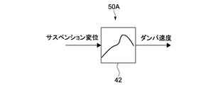
- FIG. 2 is a block diagram illustrating a configuration of the suspension displacement processing unit 50A according to the first embodiment.
- the suspension displacement processing unit 50A includes a damper speed calculation unit 42.
- the damper speed calculation unit 42 obtains suspension displacement information from the displacement sensor 13 and outputs a damper speed by performing differential calculation on the information.
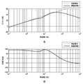
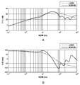
- FIG. 3A and 3B are Bode diagrams showing the differential calculation characteristics of the damper speed calculation unit 42.
- FIG. 3A shows gain characteristics
- FIG. 3B shows phase characteristics, respectively, showing a comparison with perfect differentiation.
- the characteristic of the first embodiment is indicated by a solid line
- the characteristic of complete differentiation is indicated by a broken line.
- the fully differentiated gain characteristic is used as it is, noise is generated in a high frequency region (for example, a region higher than the unsprung resonance frequency region). Therefore, in order to remove this high frequency noise, it is necessary to perform LPF (Low ⁇ Pass Filter) processing. However, there is a problem that the phase in the unsprung resonance frequency region is delayed by the LPF process.
- LPF Low ⁇ Pass Filter
- this differential operation characteristic (differential filter) has a gain characteristic with a slope larger than the slope of the fully differential gain characteristic in the unsprung resonance frequency region.
- the unsprung resonance frequency region is approximately 10 Hz to 20 Hz, and the unsprung resonance frequency according to this example is assumed to be 12 Hz.
- this differential calculation characteristic has an LPF characteristic in order to reduce noise in a higher frequency region than in the unsprung resonance frequency region as described above. Therefore, as shown in FIGS. 3A and 3B, the differential operation characteristic has a generally downward-sloping characteristic in the high frequency region.
- the differential calculation characteristic has a gain characteristic with a slope larger than the slope of the fully differentiated gain characteristic in the unsprung resonance frequency region, so that the phase lag in the unsprung resonance frequency region is compensated as shown in FIG. 3B.
- the phase characteristic according to this example is 90 deg at 12 Hz, which is the same as the fully differentiated phase. That is, the original phase characteristics of the damper speed can be obtained.
- the problem of phase delay can be solved, and the control performance when performing vehicle control using damper speed information is improved. To do.
- this differential operation characteristic further has a gain characteristic having a slope smaller than the slope of the fully differential gain characteristic in a frequency region between the sprung resonance frequency region and the unsprung resonance frequency region.
- the sprung resonance frequency region is approximately 1 Hz to 2 Hz, more broadly 0.5 Hz to 3 Hz.
- the slope of the gain once decreases in the region lower than the unsprung resonance frequency region, and increases in the unsprung resonance frequency region as described above.
- the phase is compensated so as to be almost the same value (approximately 90 degrees) as the complete differential characteristic. Thereby, the phase in the unsprung resonance frequency region can be brought close to the phase of the original damper speed.
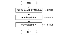
- FIG. 4 is a flowchart showing the operation of the suspension displacement processing unit 50A.
- the damper speed calculation unit 42 reads the suspension displacement (step 101), performs differential calculation using the differential calculation characteristics shown in FIGS. 3A and 3B (step 102), and outputs the damper speed (step 103).
- FIG. 5 shows another example of the damper speed calculation unit as the configuration of the suspension displacement processing unit according to the second embodiment.
- elements that are substantially the same with respect to the functions and the like included in the suspension displacement processing unit 50A according to the first embodiment will be denoted by the same reference numerals, the description thereof will be simplified or omitted, and different points will be mainly described.
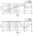
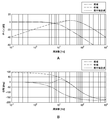
- FIGS. 6A and 6B show the differential calculation characteristics of the damper speed calculation unit 44.
- the characteristic of the second embodiment is indicated by a solid line, and the characteristic of complete differentiation is indicated by a broken line.
- the difference between this differential calculation characteristic and the differential calculation characteristics shown in FIGS. 3A and 3B is that it has a BEF (Band Elimination Filter) characteristic, that is, a notch filter characteristic, in a higher frequency region than the unsprung resonance frequency region.
- BEF Battery Elimination Filter
- the second embodiment has a serial BEF characteristic for each frequency in a region of 100 Hz to 400 Hz, for example. For example, these frequencies are 100 Hz, 200 Hz, and 400 Hz.
- the high frequency region 100 Hz to 400 Hz that is the target of noise removal is merely an example, and this region can be changed as appropriate.
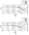
- Comparative Example 1 shows gain characteristics and phase characteristics obtained by comparing the differential operation characteristics of the second embodiment shown in FIGS. 6A and 6B with Comparative Example 1, respectively.
- the characteristic of Embodiment 2 is indicated by a solid line
- the characteristic of Comparative Example 1 is indicated by a one-dot chain line.
- Comparative Example 1 shows an example having a simple BPF (Band Pass Filter) characteristic that performs a second-order serial LPF process with respect to the complete differential characteristic.
- the phase characteristic of Comparative Example 1 confirms that a phase lag has occurred around the unsprung resonance frequency region due to the influence of the LPF process.
- the phase delay in the unsprung resonance frequency region is compensated compared to the comparative example 1, and the noise removal region of 100 Hz to 400 Hz is greatly increased. It can be seen that the gain can be reduced.
- FIGS. 8A and 8B are Bode diagrams showing an LPF characteristic that passes through a low frequency band, a BPF characteristic that passes through a mid frequency band, and a low / medium synthesis filter characteristic generated by synthesizing these.
- the design points of the low / medium synthesis filter characteristics are the unsprung resonance frequency (here, for example, around 12 Hz), the gain is about 0 dB, and the phase by separately inserting the BEF in the high range as described above. In consideration of the delay, the characteristics should be such that the phase advances to 0 deg or more in the unsprung resonance frequency region.
- the LPF transfer function order is set to 2nd order in order to increase the drop of the gain around 8Hz of the low-medium synthesis filter characteristic in the sprung resonance frequency range (1Hz to 2Hz) of the low-pass LPF characteristic. Yes.
- the fall of the BPF on the high frequency side is also set to have a second-order inclination.
- the low frequency side of the BPF is set to have a first-order inclination.
- the low and middle synthesis filter characteristics generated by combining the low frequency and the middle frequency as described above are provided with the high frequency BEF characteristics in series, and the three regions of low, medium and high are synthesized.
- the filter characteristics generated by In the figure, the filter characteristics generated by synthesizing the three regions of low, medium and high are indicated by solid lines.
- the operation of integrating the data once and returning it to the flat state is performed. By integration, both gain and phase can be set to 0 dB and 0 deg.
- the filter characteristics of low, medium and high synthesis obtained in this way are the differential operation characteristics of the second embodiment shown in FIG.
- FIGS. 10A and 10B are Bode lines showing a comparison between differential operation characteristics having a high-frequency BEF characteristic and differential operation characteristics having an LPF characteristic according to Comparative Examples 2, 3, and 4 as noise elimination measures in the region of 100 Hz to 400 Hz.
- Comparative Example 2 has a characteristic in which a first-order LPF is inserted, but there is a problem of gain reduction in a noise band that is an area of 100 Hz to 400 Hz.
- Comparative Example 3 has a characteristic in which a second-order LPF is inserted, and the phase lag compensation in the unsprung resonance frequency region is equivalent to the differential operation characteristic having a high-frequency BEF characteristic, but there is a problem that the gain decreases near 100 Hz. It becomes.
- Comparative Example 4 is a characteristic in which a third-order LPF is inserted and has a noise reduction effect that is equal to or higher than a differential calculation characteristic having a high-frequency BEF characteristic in a noise band, but a phase delay in the unsprung resonance frequency region becomes a problem.
- the differential calculation characteristic having the high-frequency BEF characteristic can solve the problems of both the gain reduction in the noise band and the phase delay in the unsprung resonance frequency area, which are contradictory as described above. it can.
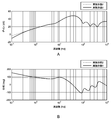
- FIG. 11A and 11B show differential calculation characteristics of the damper speed calculation unit in the suspension displacement processing unit according to the third embodiment.
- 11A and 11B show the differential operation characteristics of the second embodiment as a comparison.
- the characteristic of the third embodiment is indicated by a solid line
- the characteristic of the second embodiment is indicated by a broken line.
- the differential calculation characteristic according to the third embodiment further has an HPF (High Pass Filter) characteristic having a cutoff frequency lower than that of the sprung resonance frequency region.
- HPF High Pass Filter
- FIG. 12 shows differential calculation characteristics of the damper speed calculation unit in the suspension displacement processing unit according to the fourth embodiment.
- This differential calculation characteristic has a gain characteristic with a slope larger than the slope of the fully differential gain characteristic in the unsprung resonance frequency region. According to such characteristics, the phase lag in the unsprung resonance frequency region can be compensated. However, the gain in the unsprung resonance frequency region is larger than the gain of full differentiation.
- FIG. 13 is a block diagram illustrating a configuration of a suspension displacement processing unit according to the fifth embodiment.
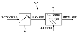
- the suspension displacement processing unit 50C includes a damper speed calculation unit 44 described in the second or third embodiment (or the first embodiment) and a low-pass to which information on the damper speed output from the damper speed calculation unit 44 is input. And an arithmetic unit 110.
- the low-pass calculation unit 110 reads vehicle motion information and has a cutoff frequency that is variable according to the vehicle motion information.
- the vehicle motion information is suspension displacement, damper speed, sprung acceleration, wheel speed, rudder angle, lateral acceleration, current value, voltage value, or information obtained by processing at least one of these values (for example, described later) This means various information such as vibration level.
- the current value and voltage value are the current value and voltage value as the control command value output to the damper, or the actual current value and voltage value actually detected by the sensor with the damper. is there.
- FIG. 14 is a flowchart showing the operation of the suspension displacement processing unit 50C.
- the damper speed calculation unit 44 reads suspension displacement (step 201), and the low-pass calculation unit 110 reads vehicle motion information (step 202).
- the damper speed calculation unit 44 calculates a temporary damper speed (step 203), and the low-pass calculation unit 110 calculates a cutoff frequency according to the vehicle motion information (step 204).
- the low-pass calculation unit 110 performs LPF calculation on the input temporary damper speed with the calculated cut-off frequency (step 205), and outputs the final damper speed (step 206).
- the damper speed output from the suspension displacement processing unit 50C is referred to as “final damper speed”.
- the noise component included in the damper speed can be removed by such a low-pass calculation unit 110.
- a scene that prioritizes the estimation accuracy of the damper speed (a scene that increases the cutoff frequency) and a scene that prioritizes noise removal (the cutoff frequency is set according to the vehicle motion information). Can be selected adaptively. Thereby, control performance improves.
- the “estimated accuracy” of the damper speed is the output accuracy of the final damper speed by the suspension displacement processing unit 50C.
- the suspension displacement processing unit 50C is configured on the assumption that the differential value of the suspension displacement is regarded as the damper speed.
- the suspension speed which is a differential value of the suspension displacement, and the original damper speed are strictly different. Therefore, in the following, it is considered to estimate the damper speed with higher accuracy by considering the transmission characteristics from the suspension speed to the damper speed.
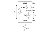
- FIG. 15 is an analysis model for examining the transmission characteristics from the suspension speed to the damper speed. The following is a description of the characters in the figure.
- the sprung mass Mb, the unsprung mass Mw, and the tire spring constant Kt are finally not included in the transmission characteristics from the suspension speed Vs to the damper speed Vd. However, these are shown in FIG. 15 for easy understanding of the explanation.
- s is a Laplace operator used in Laplace transform.
- Equation (1) the transfer characteristics change as shown in FIGS. 16A and 16B depending on the magnitude of a damper damping coefficient (hereinafter simply referred to as a damping coefficient) Cs.
- the frequency with the gain drop is a resonance frequency constituted by the mount spring constant Km and the damper rod mass Mm.
- this may be generally referred to as a mount resonance frequency, but this is not a technically accurate expression.
- the frequency called the resonance frequency of the mount strictly means the vibration frequency (frequency in a region where there is a drop in gain).
- the low-pass calculation unit 110 can estimate the damper speed with higher accuracy by using the “attenuation coefficient” as the vehicle motion information and changing the cutoff frequency according to the attenuation coefficient. become.
- FIGS. 17A and 17B show characteristics when an LPF having a variable cutoff frequency is connected in series to the differential calculation filter (see FIG. 7) of the second embodiment and the cutoff frequency is changed.
- 17A and 17B, Embodiment 2 and Comparative Example 1 are the same as those in FIG.
- the characteristic of the second embodiment is indicated by a solid line.
- the variable filters 1 and 2 have characteristics obtained by adding LPF to the second embodiment, and are indicated by a one-dot chain line and two-dot chain line, respectively.
- the cut-off frequency of the variable filter 2 is lower than that of the variable filter 1.
- the second embodiment can also be considered as a characteristic through a variable filter.
- both phase delay and high frequency noise removal in the unsprung resonance frequency region are achieved, but as a problem caused by this, for example, a gain near 40 Hz is large.
- a gain near 40 Hz is large.
- unsprung front-rear and left-right rotations and axial resonance frequencies coexist, and these components are superimposed on the detection value of the displacement sensor 13 that detects the vertical displacement of the suspension. Therefore, when the suspension displacement is small, the SN ratio may be reduced.
- the differential calculation characteristic by the damper speed calculation unit 44 is more accurate when the phase delay is larger than the simple differential characteristic. Damper speed (not suspension speed) can be estimated. By increasing the phase delay, it is possible to suppress the gain in the predetermined frequency region (in the above, around 40 Hz) of the differential calculation characteristics, and to avoid the above-described problem of the decrease in the S / N ratio.
- variable filter 1 has substantially the same gain as that of the comparative example 1 near 40 Hz, and the phase delay in the unsprung resonance frequency region is also substantially the same as that of the comparative example 1. Therefore, when the suspension displacement becomes small (when the damping coefficient becomes large), the LPF cutoff frequency can be lowered to obtain the same characteristics as Comparative Example 1 at around 40 Hz, thus avoiding the above problem. can do.
- the gain in the unsprung resonance frequency region further decreases.
- the LPF cut-off frequency is further lowered as in the characteristics of the variable filter 2 shown in FIG. 17A, so that high-precision estimation close to the original damper speed can be performed, and the above problem can be avoided. Can do.
- the damper speed and current value are required to calculate the damping coefficient.
- the above theory is contradictory because an attempt is made to use a damping coefficient for calculating the damper speed. (However, practically, the attenuation coefficient can be tentatively estimated by a method described later.)
- the “unsprung vibration level”, which is the magnitude of the unsprung vibration that is dominant as the damper speed component, can be used as a substitute for the damping coefficient in practical use.
- an embodiment using an unsprung vibration level as vehicle motion information will be described.
- FIG. 18 is a block diagram illustrating a configuration of a suspension displacement processing unit according to the sixth embodiment.
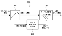
- the low-pass calculation unit 120 in the suspension displacement processing unit 50D includes, for example, an unsprung vibration level calculation unit 210 that calculates an unsprung vibration level based on unsprung acceleration.
- the unsprung vibration level means any one of the unsprung acceleration, unsprung speed, and unsprung displacement.
- the unsprung acceleration is detected by an unsprung acceleration sensor (not shown) as described above.
- Most of the acceleration components obtained by the unsprung acceleration sensor indicate vibration components of unsprung acceleration, and unlike the “damper speed”, as will be described later, almost no frequency component of sprung acceleration is included. Therefore, the calculation unit can calculate the unsprung vibration level with high accuracy. Moreover, even if any information is used among unsprung acceleration, unsprung speed, and unsprung displacement, they only differ in unit, and this difference does not affect the calculation accuracy.
- the unsprung “vibration level” for example, an envelope of the vibration amplitude is employed as shown in FIG.
- an envelope calculation means for example, a peak hold process at every predetermined timing or a process such as Hilbert transform is performed on a waveform subjected to full-wave rectification.
- a peak hold process at every predetermined timing or a process such as Hilbert transform is performed on a waveform subjected to full-wave rectification.
- various means can be used without being limited thereto.
- the unsprung vibration level is not limited to the envelope, and may be, for example, the vibration amplitude itself of the unsprung resonance frequency signal.
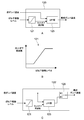
- FIG. 19A is a block diagram showing a configuration of the low-pass calculation unit 120.
- the low-pass calculation unit 120 includes a map 121 and an LPF unit 125.
- FIG. 19B shows an example in which the map 121 is graphed.
- the map 121 is a look-up table showing the correspondence between the unsprung vibration level and the cutoff frequency.
- the cutoff frequency is set to be larger as the unsprung vibration level is larger. Outside the predetermined region of the unsprung vibration level, the cutoff frequency is a constant value of the upper limit value and the lower limit value.
- the graph shape of the map 121 is not limited to that shown in FIG. 19B and may include a curve.
- FIG. 21 is a flowchart showing the operation of the suspension displacement processing unit 50D.
- the damper speed calculation unit 44 reads the suspension displacement (step 301), and the unsprung vibration level calculation unit 210 reads the unsprung acceleration (step 302).
- the damper speed calculation unit 44 calculates the temporary damper speed (step 303), and the unsprung vibration level calculation unit 210 calculates the unsprung vibration level by obtaining the envelope as shown in FIG. 304).
- the low-pass calculation unit 120 refers to the map 121 and calculates a cutoff frequency corresponding to the input unsprung vibration level (step 305).
- the LPF unit 125 performs an LPF operation on the input temporary damper speed with the calculated cutoff frequency (step 306). As a result, the final damper speed is output (step 307).
- the damper speed is a differential value of the suspension displacement, which is the relative displacement between the sprung and unsprung parts, and is the relative speed between the sprung speed and the unsprung speed. Therefore, the damper speed mainly includes the sprung frequency component and the unsprung frequency component. Since the sprung resonance frequency is sufficiently lower than the unsprung resonance frequency, the damper speed is not easily increased by the sprung vibration, and the damper speed is likely to be increased by the unsprung vibration.
- a feature common to all the embodiments of the present invention is that the phase lag in the unsprung resonance frequency region is relaxed (compensated) when calculating the damper speed.
- the damper speed is very small and there is no need to mitigate the phase lag in the unsprung resonance frequency region.
- the signal level of the sprung resonance frequency is relatively high and the SN ratio is lowered. In this case, a low cut-off frequency is calculated, so that noise removal is prioritized. Is appropriate.
- phase delay compensation function which is the above feature, may be exhibited.
- the unsprung vibration level is directly calculated from the unsprung acceleration, so that unsprung vibration can be detected with certainty.
- a low-pass calculation unit 120 ′ as shown in FIG. 19C may be provided.
- the low-pass operation unit 120 ′ includes a switch 126. Based on the cut-off frequency calculated in step 305, the switch 126 switches whether the input temporary damper speed is input to the LPF unit 125 or is passed through without passing through the LPF unit 125. That is, the switch 126 functions as a “switching unit” that switches between the functioning of the low-pass arithmetic unit 120 and the stop thereof.
- the switch 126 can output the temporary damper speed as the final damper speed as it is.
- the low-pass calculation unit 120 uses the map 121 for calculating the cut-off frequency, but may calculate the cut-off frequency by calculation using a predetermined calculation formula.
- maps that appear in the following embodiments, and an arithmetic expression may be used instead of the map.
- FIG. 22 is a block diagram illustrating a configuration of a suspension displacement processing unit according to the seventh embodiment.
- the difference between the sixth and seventh embodiments is that the unsprung vibration level calculation unit 220 in the suspension displacement processing unit 50E calculates the unsprung vibration level based on the temporary damper speed output from the damper speed calculation unit 44. is there.
- FIG. 23 is a block diagram illustrating a configuration of the unsprung vibration level calculation unit 220.
- the unsprung vibration level calculation unit 220 includes a BPF 201 and a calculation unit 202.
- the BPF 201 extracts the frequency component of unsprung vibration from the frequency component of the temporary damper speed obtained by the damper speed calculation unit 44.
- the calculation unit 202 calculates an unsprung vibration level from the unsprung vibration of the extracted frequency component.
- the information used for calculating the unsprung vibration level is not limited to the damper speed, and may be a differentiated damper acceleration or a damper displacement.
- the damper speed when used, the noise component may be increased.
- the suspension displacement when using the damper displacement, the suspension displacement can be used as it is, but since the amplitude of the low frequency component becomes relatively large, in order to remove the low frequency component, the low frequency ratio is high in the low frequency region. It is necessary to apply a filter, which makes filter design difficult. Therefore, it is most preferable to use the damper speed.
- FIG. 24 is a flowchart showing the operation of the suspension displacement processing unit 50E.
- the damper speed calculation unit 44 reads the suspension displacement (step 401) and calculates a temporary damper speed (step 402).
- the unsprung vibration level calculation unit 220 calculates the unsprung vibration level based on the temporary damper speed (step 403).
- the low-pass calculation unit 120 refers to the map 121 (see FIG. 19) and calculates a cutoff frequency corresponding to the input unsprung vibration level (step 404).
- the LPF unit 125 performs a low-pass operation on the input temporary damper speed with the calculated cutoff frequency (step 405). As a result, the final damper speed is output (step 406).
- the seventh embodiment for example, it is not necessary to provide an unsprung acceleration sensor as in the sixth embodiment, so that the cost is not increased.
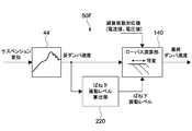
- FIG. 25 is a block diagram illustrating a configuration of a suspension displacement processing unit according to the eighth embodiment.
- the difference between the seventh and eighth embodiments is that the low-pass calculation unit 140 in the suspension displacement processing unit 50F takes in a damping coefficient corresponding value in addition to the unsprung vibration level as vehicle motion information.
- the attenuation coefficient corresponding value is a value corresponding to a change in the attenuation coefficient of the damper, and is, for example, a current value (voltage value) that causes the attenuation characteristic to function.
- the current value may be the current actual current value (or actual voltage value) actually detected by the current detector (or voltage detector), or the control calculation unit 300 (see FIG. 1). It may be a control command value to the damper output before or before.
- FIG. 26A is a block diagram showing a configuration of the low-pass calculation unit 140.
- the low-pass calculation unit 140 has a configuration in which a map 122 and a calculation unit 141 are further added to the configuration of the sixth embodiment illustrated in FIG.
- the damping characteristic (that is, the damping coefficient) of the proportional solenoid type semi-active damper generally increases as the current value increases, and the damper becomes harder. Conversely, the lower the current value, the smaller the damping coefficient and the softer the damper. Therefore, the attenuation coefficient can be estimated from the current value.
- the opening of the proportional solenoid valve of the damper is determined by the current value when the proportional solenoid is energized.
- the damping force increases as the damper speed increases.
- the two are not in a linear relationship, and the rate of change in damping force increases as the damper speed decreases, and the rate of change in damping force decreases in the region where the damper speed is high.
- FIG. 26B shows an example of the map 122.
- a map 122 shows the relationship between the attenuation coefficient and the cutoff frequency.
- the cutoff frequency is set to be smaller as the attenuation coefficient is larger within a predetermined area of the attenuation coefficient. Outside the predetermined region of the attenuation characteristic, the cut-off frequency is a constant value of the upper limit value and the lower limit value. In this case, as described above, the attenuation coefficient can be replaced with a current value.
- the cut-off frequencies a and b calculated by referring to the maps 121 and 122 are input to the calculation unit 141.
- the calculation unit 141 performs a predetermined calculation based on these cutoff frequencies a and b, and outputs one final cutoff frequency.
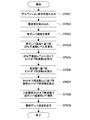
- FIG. 27 is a flowchart showing the operation of the suspension displacement processing unit 50F.
- the damper speed calculator 44 reads the suspension displacement (step 501), and the low-pass calculator 140 reads the current value (step 502).
- the damper speed calculation unit 44 calculates the temporary damper speed (step 503), and the unsprung vibration level calculation unit 220 calculates the unsprung vibration level based on the temporary damper speed (step 504).
- the low-pass calculation unit 140 refers to the map 121 and calculates a cutoff frequency a corresponding to the input unsprung vibration level (step 505). Further, the low-pass calculation unit 140 refers to the map 122 and calculates a cutoff frequency b corresponding to the input current value (step 506).
- the computing unit 141 reads both cutoff frequencies a and b, and outputs the final cutoff frequency based on these (step 507).
- the LPF unit 125 performs a low-pass operation on the input temporary damper speed at the final cutoff frequency (step 508). As a result, the final damper speed is output (step 509).
- the transfer characteristic from the suspension speed to the damper speed changes according to the value of the damping coefficient.
- the damping coefficient is determined by a plurality of types (two types here) of vehicle motion information of the damper speed and current value (dynamic characteristics are ignored as will be described later). For this reason, in the low-pass calculation unit 140, it is possible to change the damper speed in a state closer to the actual characteristics by changing the cut-off frequency with only one type of vehicle motion information rather than changing with the two types of vehicle motion information. It is possible to calculate, the output accuracy of the damper speed is improved, and the control performance is improved.
- FIGS. 28A to 28C are diagrams for explaining a calculation example by the calculation unit 141 in the low-pass calculation unit 140 of the eighth embodiment.
- Embodiment 8-1 The arithmetic unit in the form shown in FIG. 28A includes a row select unit 141a.
- the row select unit 141a reads both cutoff frequencies a and b, compares them, and selects and outputs the cutoff frequency having the lower value.
- the state that originally has no LPF is the most suitable state for the purpose because the damper speed in which the phase lag is suppressed in the unsprung resonance frequency region is calculated.
- the present embodiment 8-1 there is a case where it is better to delay the phase by adding a filter in a certain situation. In this case, the lower cutoff frequency should be given priority. .
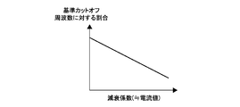
- FIG. 29 shows an example of the map 123.
- the map 123 describes a correspondence relationship between a damping coefficient (that is, a current value) and a ratio to a cutoff frequency (hereinafter referred to as a reference cutoff frequency) determined based on the unsprung vibration level by the map 121. is there. That is, the low-pass calculation unit refers to the map 123 and outputs a ratio value with respect to the reference cutoff frequency based on the input current value.
- the graph 123 has a linear graph shape, but may be curved or non-linear.
- the low-pass calculation unit includes a multiplication unit 141b that reads the reference cutoff frequency and the ratio value as the calculation unit 141.
- the multiplier 141b outputs a final cutoff frequency obtained by multiplying the input reference cutoff frequency by the input ratio value.
- the low-pass arithmetic unit of the form shown in FIG. 28C has a map 124 instead of the map 121, and has the above-described map 122 (see FIG. 26B), similarly to the idea of the form 8-2.
- the map 124 describes the relationship between the unsprung vibration level and the ratio to the reference cutoff frequency determined based on the current value by the map 122. That is, the low-pass calculation unit refers to the map 124 and outputs a ratio value with respect to the reference cutoff frequency based on the input unsprung vibration level.
- the multiplier 141b outputs a final cutoff frequency obtained by multiplying the reference cutoff frequency by the ratio value.
- the low-pass calculation unit can perform the following processing.
- the low-pass calculation unit basically changes the cut-off frequency according to the unsprung vibration level, and further changes the cut-off frequency according to the current value in a region where the unsprung vibration level is equal to or lower than a predetermined value. It may be. Such processing further improves the control performance.
- the low-pass calculation unit may further reduce the cut-off frequency as the current value increases, for example, in a low unsprung vibration level, that is, in a low-speed damper speed region.
- subtraction may be used in addition to multiplication.
- the reference cutoff frequency is determined based on the unsprung vibration level or the current value.
- the subtracted value for the determined reference cutoff frequency is matched to the current value or unsprung vibration level.
- the subtracting unit as the calculating unit 141 can perform a process of subtracting the subtraction value determined by the other map from the reference cutoff frequency determined by one map.
- FIG. 30 is a block diagram illustrating a configuration of a suspension displacement processing unit according to the ninth embodiment.
- the configuration of the unsprung vibration level calculation unit 230 in the suspension displacement processing unit 50G is different from the above embodiment.
- the form of the low-pass calculation unit 120 is a form that does not read the current value (similar to FIG. 22).
- FIG. 31 is a block diagram illustrating a configuration of the unsprung vibration level calculation unit 230.
- the unsprung vibration level calculation unit 230 includes the same elements as the BPF 201 and the calculation unit 202 in the unsprung vibration level calculation unit 220 illustrated in FIG. 23, and further includes a map 203 and an LPF unit 204.
- a map 203 describes the correspondence relationship between the input temporary damper speed and the cutoff frequency of the subsequent LPF unit 204. That is, in the unsprung vibration level calculation unit 230, the LPF unit 204 performs the LPF calculation at the cutoff frequency calculated according to the temporary damper speed by the map 203.
- the unsprung vibration level calculation unit 230 can calculate a highly accurate unsprung vibration level by LPF processing at a cutoff frequency corresponding to the input temporary damper speed.
- FIG. 32 is a flowchart showing the operation of the suspension displacement processing unit 50G.
- the unsprung vibration level calculation unit 230 performs LPF calculation (variable LPF calculation) at a cutoff frequency corresponding to the temporary damper speed, and outputs the unsprung vibration level from which noise has been removed to the low-pass calculation unit 120. To do.
- the low-pass calculation unit 120 can output the final damper speed with the fluctuation reduced.
- the low-pass calculation unit 120 of the ninth embodiment may have the same function as the low-pass calculation unit 140 of the eighth embodiment, and may read the current value and change the cutoff frequency.
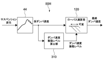
- FIG. 33 is a block diagram illustrating a configuration of a suspension displacement processing unit according to the tenth embodiment.
- a difference between the suspension displacement processing unit 50H according to the tenth embodiment and the seventh embodiment (see FIG. 22) is that a damper speed vibration level calculation unit 310 is used instead of the unsprung vibration level calculation unit 220 in the seventh embodiment. It is a point provided.
- the damper speed vibration level calculation unit 310 reads the temporary damper speed output from the damper speed calculation unit 44, and calculates the damper speed vibration level based on the temporary damper speed.
- the damper speed vibration level calculation unit 310 outputs this to the low-pass calculation unit 120 as vehicle motion information.
- the calculation of the damper speed vibration vibration level is typically realized by calculating an envelope, similar to the calculation of the unsprung vibration level described above.
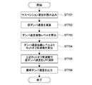
- FIG. 34 is a flowchart showing the operation of the suspension displacement processing unit 50H.
- steps different from the operation (see FIG. 24) of the suspension displacement processing unit 50E of the seventh embodiment are steps 703 to 705. That is, the damper speed vibration level calculation unit 310 calculates the damper speed vibration level (step 703).
- the low-pass calculation unit 120 reads the damper speed vibration level, calculates a cutoff frequency corresponding to the damper speed vibration level (step 704), and performs an LPF calculation on the damper speed at this cutoff frequency (step 705).
- the suspension displacement processing unit 50H directly determines the vehicle motion state in the minute damper speed region where the SN ratio of the damper speed is deteriorated based on the damper speed vibration level, the damper speed can be reliably detected. As a result, it is possible to avoid deterioration of control performance due to deterioration of the SN ratio.
- the frequency component of the damper speed includes not only the unsprung frequency component but also the sprung frequency component. Therefore, in order to calculate the final damper speed with higher accuracy, it is preferable to use the unsprung vibration level as the vehicle motion information as in the sixth to ninth embodiments.
- FIG. 35 is a block diagram illustrating a configuration of a suspension displacement processing unit according to the eleventh embodiment.
- the difference between the suspension displacement processing unit 50I according to the eleventh embodiment and the seventh embodiment (see FIG. 22) is that a plurality of LPFs 70 and switching means 80 are provided instead of the low-pass calculation unit 120 of the seventh embodiment.
- the real-time property is not prioritized.
- Each LPF of the plurality of LPFs 70 has a different cutoff frequency.
- the switching unit 80 selectively switches use of the plurality of LPFs 70 according to the vehicle motion information.
- the unsprung vibration level calculated by the unsprung vibration level calculation unit 220 is used as the vehicle motion information.
- FIG. 36 is a flowchart showing the operation of the suspension displacement processing unit 50I.
- steps different from the operation (see FIG. 24) of the suspension displacement processing unit 50E of the seventh embodiment are steps 804 and 805.
- the switching unit 80 selects one of the plurality of LPFs 70 in accordance with the input unsprung vibration level (step 804), and performs LPF calculation on the temporary damper speed using this LPF (step 805).
- Embodiment 11 is a form in which priority is not given to real-time characteristics compared to the above-described embodiments, but it is possible to output a highly accurate final damper speed.
- the suspension displacement processing unit 50I may calculate the final damper speed while linearly complementing the outputs of these LPFs.
- the vehicle motion information may be a damper speed vibration level as in the tenth embodiment, instead of the unsprung vibration level.
- FIG. 37 is a block diagram illustrating a configuration of a suspension displacement processing unit according to the twelfth embodiment.
- the damper speed calculation unit 44 is provided at the subsequent stage of the low-pass calculation unit 120.
- the damper speed calculation unit 44 has the differential calculation characteristics shown in the second or third embodiment (or the first and fourth embodiments).
- FIG. 38 is a flowchart showing the operation of the suspension displacement processing unit 50J.
- the low-pass calculator 120 reads the suspension displacement (step 901).
- the unsprung vibration level calculation unit 230 reads the unsprung acceleration from the unsprung acceleration sensor (step 902), and based on this, calculates the unsprung vibration level as vehicle motion information (step 903).
- the low-pass calculation unit 120 calculates a cutoff frequency based on the unsprung vibration level (step 904), and performs an LPF calculation on the suspension displacement at the cutoff frequency (step 905).
- the damper speed calculation unit 44 reads this suspension displacement, calculates the damper speed using the differential calculation characteristic (step 906), and outputs this as the final damper speed (step 907).
- the vehicle motion information is not limited to the unsprung vibration level, and can be replaced with various information as described above.
- a damper speed vibration level calculation unit 310 may be used.
- FIGS. 39A and 39B are block diagrams respectively showing the configuration of the damper speed calculation unit in the suspension displacement processing unit according to the thirteenth embodiment.
- the differential calculation characteristic by the damper speed calculation unit is divided into two calculation characteristics.
- the damper speed calculation unit 45 shown in FIG. 39A has a first calculation unit 45a having a BPF characteristic and a differential calculation characteristic having a gain characteristic with a slope larger than the slope of the fully differential gain characteristic in the unsprung resonance frequency region. 2nd calculating part 45b.
- the differential calculation characteristic in the second calculation unit 45b may have any of the characteristics in the first to fourth embodiments.
- the differential calculation characteristics of Embodiments 1 to 3 and the like described above have a phase characteristic in which the phase is 90 degrees, which is the same as the full differential, at the resonance frequency (for example, 12 Hz) in the unsprung resonance frequency region.
- the phase does not necessarily need to be 90 deg at the unsprung resonance frequency, and the setting may be such that the phase is 90 deg ⁇ ⁇ deg at the unsprung resonance frequency.
- the current value (attenuation coefficient) is used as one of the two pieces of vehicle motion information.
- the current value is a control command value output by the control calculation unit 300 or an actual current value.
- the attenuation coefficient may be an attenuation coefficient calculated based on the temporary damper speed output from the damper speed calculation unit.
- the attenuation characteristic actually has hysteresis due to the influence of the dynamic characteristic. For example, by calculating the attenuation coefficient from the static characteristic data of the attenuation characteristic (hysteresis is ignored), the attenuation characteristic corresponds to this attenuation coefficient.
- the cut-off frequency by the low-pass calculation unit can be changed.
- the damper speed may be used as vehicle vibration information instead of the unsprung vibration level as in the tenth embodiment (see FIG. 33), or other information. May be used. The same applies to Embodiments 8-1, 8-2, and 8-3 shown in FIG.
- the damping coefficient of the semi-active damper using the proportional solenoid valve increases as the current value increases.
- the damping factor may decrease as the current value increases.
- a four-wheeled vehicle is taken as an example of a vehicle, but the technology of each of the above-described embodiments can be applied to a two-wheeled vehicle, a train vehicle, and the like.
- the unsprung vibration level calculation unit 210 shown in FIG. 18 may read the wheel speed from the wheel speed sensor 15 instead of reading the unsprung acceleration from the unsprung acceleration sensor.
- the unsprung vibration level calculation part should just output the signal which extracted the frequency component resulting from unsprung vibration from the signal of wheel speed.
- the unsprung vibration level can be obtained with or without differentiating the wheel speed.
- adjustment of the unit system is necessary.
- the modification of the sixth embodiment shown in FIG. 19C can also be applied to the low-pass arithmetic units of the fifth and seventh to thirteenth embodiments described below.
- the unsprung vibration level calculation unit of the thirtieth embodiment shown in FIG. 30 reads the temporary damper speed, but as information in place of the temporary damper speed, unsprung acceleration may be used as shown in FIG.
- the wheel speed may be used.
- the form shown in the embodiment 13A or 13B may be applied to the embodiments 5 to 12.
Landscapes
- Engineering & Computer Science (AREA)
- Mechanical Engineering (AREA)
- Vehicle Body Suspensions (AREA)
Abstract
【課題】位相遅れを抑制し、制御性能が向上したサスペンション制御装置、これに用いられる信号処理装置および信号処理方法を提供すること。 【解決手段】ダンパ速度演算部42は、サスペンション変位を読み込み、これを微分演算することで、ダンパ速度を算出する。この微分演算特性は、ばね下共振周波数領域で、完全微分のゲイン特性の傾きより大きい傾きのゲイン特性を有する。これにより、位相遅れを抑制し、制御性能が向上する。
Description
本発明は、車両のサスペンションを制御するサスペンション制御装置、これに用いられる信号処理装置およびその方法に関する。
従来から、車両のサスペンションシステムとして、スカイフック理論に基づいて、サスペンションをアクティブに制御することにより、乗り心地および操縦安定性を両立させるようにしたアクティブサスペンションシステムがある。アクティブサスペンションシステムの方式の1つであるセミアクティブサスペンションシステムは、減衰力(厳密には減衰特性)可変のショックアブソーバ(ダンパ)を用い、減衰力が制振方向に働く時にその減衰特性を可変に制御するものである。
特許文献1には、ダンパ変位センサで検出されたダンパ変位を微分フィルタを通過させて時間微分することで、ダンパ速度を算出し、このダンパ速度を用いてマップ検索によりダンパに供給する目標電流を算出する例が記載されている。ここで、ばね下共振周波数領域までの制御を確実に行うべく位相遅れを最小限に抑えた微分フィルタを設計すると、出力されるダンパ速度信号に高周波ノイズが発生する(例えば、特許文献1の段落[0004]参照)。
特許文献1に記載の装置は、上記高周波ノイズを除去するために、ばね下共振周波数領域を通過させるローパスフィルタにより、制御量である目標電流の信号をフィルタリングしている。しかしながら、制御量にローパスフィルタ処理を行うと、その制御量にやはり位相遅れが発生するため、制御性能が低下するという問題がある。
したがって、本発明の目的は、位相遅れを抑制し、制御性能が向上したサスペンション制御装置、これに用いられる信号処理装置および信号処理方法を提供することにある。
上記目的を達成するため、本発明の一形態に係る信号処理装置は、サスペンション変位を読み込み、ダンパ速度を出力する信号処理装置であって、ダンパ速度演算部を具備する。ダンパ速度演算部は、ばね下共振周波数領域で、完全微分のゲイン特性の傾きより大きい傾きのゲイン特性を有する微分演算特性を用いて、前記サスペンション変位を微分するように構成される。
これにより、この信号処理装置を備えるサスペンション制御装置による振動制御において、ばね下共振周波数領域でのダンパ速度の位相遅れを抑制できるので、制御性能が向上する。
これにより、この信号処理装置を備えるサスペンション制御装置による振動制御において、ばね下共振周波数領域でのダンパ速度の位相遅れを抑制できるので、制御性能が向上する。
前記ダンパ速度演算部は、ばね上共振周波数領域と前記ばね下共振周波数領域との間の周波数領域で、前記完全微分のゲイン特性の傾きより小さい傾きのゲイン特性をさらに有する微分演算特性を用いてもよい。
これにより、ばね下共振周波数領域で、完全微分のゲイン、つまり本来のダンパ速度のゲインより、ゲインが大きくなることを回避することができる。また、ばね下共振周波数領域における位相を、本来のダンパ速度の位相に近づけることができる。
これにより、ばね下共振周波数領域で、完全微分のゲイン、つまり本来のダンパ速度のゲインより、ゲインが大きくなることを回避することができる。また、ばね下共振周波数領域における位相を、本来のダンパ速度の位相に近づけることができる。
前記ダンパ速度演算部は、前記ばね下共振周波数領域で、完全微分の位相と同じになる位相を含む位相特性を有する微分演算特性を用いてもよい。
すなわち、ばね下共振周波数領域で、本来のダンパ速度の位相を含む位相特性を得ることができる。
すなわち、ばね下共振周波数領域で、本来のダンパ速度の位相を含む位相特性を得ることができる。
前記ダンパ速度演算部からのダンパ速度が入力され、車両運動情報に応じて可変なカットオフ周波数を有するローパス演算部をさらに具備してもよい。
ローパス演算部により、ダンパ速度に含まれるノイズ成分を除去することができる。また、そのカットオフ周波数が可変であるので、車両運動情報に応じて、ダンパ速度の出力精度を優先する場面と、ノイズ除去を優先する場面とを適応的に分けることができ、制御性能が向上する。
ローパス演算部により、ダンパ速度に含まれるノイズ成分を除去することができる。また、そのカットオフ周波数が可変であるので、車両運動情報に応じて、ダンパ速度の出力精度を優先する場面と、ノイズ除去を優先する場面とを適応的に分けることができ、制御性能が向上する。
前記信号処理装置は、前記車両運動情報に応じて算出されたカットオフ周波数に基づき、前記ローパス演算部を機能させることおよびその停止を切り替える切替部をさらに具備してもよい。
これにより、車両運動情報に応じて適切なダンパ速度の情報が得られ、さらに制御性能が向上する。
これにより、車両運動情報に応じて適切なダンパ速度の情報が得られ、さらに制御性能が向上する。
前記信号処理装置は、前記サスペンション変位が入力され、車両運動情報に応じて可変なカットオフ周波数を有するローパス演算部をさらに具備してもよい。そして、前記ローパス演算部によりローパス演算された前記サスペンション変位が、前記ダンパ速度演算部に入力されてもよい。
ローパス演算部により、ダンパ速度情報に含まれるノイズ成分を除去することができる。また、そのカットオフ周波数が可変であるので、車両運動情報に応じて、ダンパ速度の出力精度(算出精度)を優先する場面と、ノイズ除去を優先する場面とを適応的に分けることができ、制御性能が向上する。
ローパス演算部により、ダンパ速度情報に含まれるノイズ成分を除去することができる。また、そのカットオフ周波数が可変であるので、車両運動情報に応じて、ダンパ速度の出力精度(算出精度)を優先する場面と、ノイズ除去を優先する場面とを適応的に分けることができ、制御性能が向上する。
前記信号処理装置は、前記車両運動情報として、ばね下振動レベルを算出する算出部をさらに具備してもよい。
これにより、ローパス演算部は、ばね下振動レベルに基づいてカットオフ周波数を変化させることができる。
これにより、ローパス演算部は、ばね下振動レベルに基づいてカットオフ周波数を変化させることができる。
前記算出部は、ばね下加速度に基づき、前記ばね下振動レベルを算出してもよい。
つまり、算出部は、上記のようにダンパ速度からその振動レベルを算出するのではなく、ばね下加速度からばね下振動レベルを算出する。したがって、確実にばね下振動を検知でき、ダンパ速度の出力精度を優先する場面と、ノイズ除去を優先する場面とを適応的に分けることができ、制御性能が向上する。
つまり、算出部は、上記のようにダンパ速度からその振動レベルを算出するのではなく、ばね下加速度からばね下振動レベルを算出する。したがって、確実にばね下振動を検知でき、ダンパ速度の出力精度を優先する場面と、ノイズ除去を優先する場面とを適応的に分けることができ、制御性能が向上する。
前記算出部は、ばね下加速度に応じて可変なカットオフ周波数を有するローパスフィルタ部を有してもよい。
前記算出部は、前記ダンパ速度演算部によって演算される前記ダンパ速度に基づき、前記ばね下振動レベルを算出してもよい。
本発明によれば、ばね下加速度センサを設ける必要がないので、コストアップを招くことがない。
本発明によれば、ばね下加速度センサを設ける必要がないので、コストアップを招くことがない。
前記算出部は、上記同様に、前記ダンパ速度演算部によって演算される前記ダンパ速度に応じて可変なカットオフ周波数を有するローパスフィルタ部を有してもよい。
ダンパ速度の大きさによってはSN比が低下する場合があり、その場合、ばね下振動レベルが変動しやすい状況にある。この変動が、最終のダンパ速度の出力結果に影響を与えるおそれがある。本発明によれば、算出部のフィルタ部が、ダンパ速度に応じて可変なカットオフ周波数を有するので、ばね下振動レベルの変動が低減され、信号処理装置は、変動が低減されたダンパ速度を最終的に出力することができる。
ダンパ速度の大きさによってはSN比が低下する場合があり、その場合、ばね下振動レベルが変動しやすい状況にある。この変動が、最終のダンパ速度の出力結果に影響を与えるおそれがある。本発明によれば、算出部のフィルタ部が、ダンパ速度に応じて可変なカットオフ周波数を有するので、ばね下振動レベルの変動が低減され、信号処理装置は、変動が低減されたダンパ速度を最終的に出力することができる。
前記ローパス演算部は、複数種類の車両運動情報に基づき、前記カットオフ周波数を算出してもよい。
ローパス演算部は、複数種類の車両運動情報を得ることにより、状況に応じて適切に、高精度なダンパ速度を出力することができる。
ローパス演算部は、複数種類の車両運動情報を得ることにより、状況に応じて適切に、高精度なダンパ速度を出力することができる。
前記ローパス演算部は、ばね下振動レベル、および、ダンパの減衰係数の変化に対応する減衰係数対応値に基づき、カットオフ周波数を算出してもよい。
これにより、信号処理装置は、ばね下振動レベルだけでなく、減衰係数対応値に対応するダンパの減衰係数を用いて演算を行うことができる。これにより、より実際の特性に近い状態でダンパ速度を算出でき、ダンパ速度の出力精度が向上し、制御性能が向上する。
これにより、信号処理装置は、ばね下振動レベルだけでなく、減衰係数対応値に対応するダンパの減衰係数を用いて演算を行うことができる。これにより、より実際の特性に近い状態でダンパ速度を算出でき、ダンパ速度の出力精度が向上し、制御性能が向上する。
前記ローパス演算部は、前記ばね下振動レベルに基づき算出されるカットオフ周波数と、前記減衰係数対応値に基づき算出されるカットオフ周波数とに基づき、1つのカットオフ周波数を算出してもよい。
前記ローパス演算部は、ローセレクト処理により前記1つのカットオフ周波数を出力するローセレクト部を有してもよい。
前記ローパス演算部は、前記減衰係数対応値に基づき割合値を算出し、前記ばね下振動レベルに基づき算出される基準カットオフ周波数に、前記割合値を乗じる乗算部を有してもよい。
前記ローパス演算部は、前記ばね下振動レベルに基づき割合値を算出し、前記減衰係数対応値に基づき算出される基準カットオフ周波数に、前記割合値を乗じる乗算部を有してもよい。
前記信号処理装置は、異なる複数のカットオフ周波数で、前記ダンパ速度演算部からのダンパ速度についてそれぞれローパスフィルタ処理を行う複数のローパスフィルタと、車両運動情報に応じて、前記複数のローパスフィルタの使用を選択的に切り替える切替手段とをさらに具備してもよい。
これにより、信号処理に用いられる情報処理量を少なくし、制御を簡易化することができる。
これにより、信号処理に用いられる情報処理量を少なくし、制御を簡易化することができる。
前記ダンパ速度演算部は、前記ばね下共振周波数領域より高い周波数領域でバンドエリミネーションフィルタ特性をさらに有する微分演算特性を用いてもよい。
これにより、ばね下共振周波数領域でのダンパ速度の位相遅れの補償と、高周波ノイズ除去を両立させることができるため、制御性能が向上する。
これにより、ばね下共振周波数領域でのダンパ速度の位相遅れの補償と、高周波ノイズ除去を両立させることができるため、制御性能が向上する。
前記ダンパ速度演算部は、前記ばね下共振周波数領域より高い周波数ごとの直列的な前記バンドエリミネーションフィルタ特性をさらに有する微分演算特性を用いてもよい。
これにより、上記位相遅れ補償および高周波ノイズ除去の効果を促進させることができる。
これにより、上記位相遅れ補償および高周波ノイズ除去の効果を促進させることができる。
前記ダンパ速度演算部は、前記ばね上共振周波数領域より低いカットオフ周波数を持つハイパスフィルタ特性をさらに有する微分演算特性を用いてもよい。
これにより、ばね上共振周波数領域の位相特性を完全微分の位相特性に近づけることができる。すなわち、ばね上共振周波数領域で、本来のダンパ速度の位相を含む位相特性を得ることができる。
これにより、ばね上共振周波数領域の位相特性を完全微分の位相特性に近づけることができる。すなわち、ばね上共振周波数領域で、本来のダンパ速度の位相を含む位相特性を得ることができる。
本発明の一形態に係るサスペンション制御装置は、上記のダンパ速度演算部と、前記ダンパ速度に基づき、ダンパを制御する制御指令値を生成する制御演算部とを具備する。
これにより、サスペンション制御装置による振動制御において、ばね下共振周波数領域でのダンパ速度の位相遅れを抑制できるので、制御性能が向上する。
これにより、サスペンション制御装置による振動制御において、ばね下共振周波数領域でのダンパ速度の位相遅れを抑制できるので、制御性能が向上する。
本発明の一形態に係る信号処理方法は、サスペンション変位を読み込むことを含む。
そして、ばね下共振周波数領域で、完全微分のゲイン特性の傾きより大きい傾きのゲイン特性を有する微分演算特性を用いて、前記読み込んだサスペンション変位が微分される。
そして、ばね下共振周波数領域で、完全微分のゲイン特性の傾きより大きい傾きのゲイン特性を有する微分演算特性を用いて、前記読み込んだサスペンション変位が微分される。
以上、本発明によれば、位相遅れを抑制し、制御性能が向上する。
以下、図面を参照しながら、本発明の実施形態を説明する。
[サスペンション制御システム]
図1は、本発明の一実施形態に係るサスペンション制御システムを示すブロック図である。このサスペンション制御システム1は、車両として、典型的には4輪自動車に採用され得る。サスペンション制御システム1は、複数のセンサ類を含むセンサ部10と、センサ部10からの各種の検出値に基づき、図示しないサスペンションの動きを制御するサスペンション制御装置20とを備える。
図1は、本発明の一実施形態に係るサスペンション制御システムを示すブロック図である。このサスペンション制御システム1は、車両として、典型的には4輪自動車に採用され得る。サスペンション制御システム1は、複数のセンサ類を含むセンサ部10と、センサ部10からの各種の検出値に基づき、図示しないサスペンションの動きを制御するサスペンション制御装置20とを備える。
センサ部10は、例えば、ばね上加速度センサ11、変位センサ13、車輪速センサ15等、車両の挙動に関連する情報を与える各種のセンサを備える。
ばね上加速度センサ11は、例えば車体(例えばシャーシ)に取り付けられ、ばね上加速度を検出する。変位センサ13は、車高センサとも呼ばれ、例えば車体またはサスペンションアームに取り付けられ、これらの間の相対変位、つまり、ばね上とばね下との相対変位を検出する。以降の説明では、このばね上とばね下との相対変位を、サスペンション変位という。車輪速センサ15は、車輪速を検出し、例えばホイールハブに取り付けられる。
なお、センサ部10は、ばね上加速度センサ11、変位センサ13および車輪速センサ15の他、ばね下加速度センサ、舵角センサ等も含む場合もある。
これらのセンサ種類はあくまで一例であり、車種によってその仕様が異なることもある。また、センサ数も車種等によって適宜設定される。例えば、変位センサ13が4輪のうち2輪のみに設けられていたり、ばね上加速度センサ11が単数または複数であったりする。
また、上記すべてのセンサが1つの車両に搭載されるわけではない。例えば、ばね下加速度センサおよび変位センサ13のうち、いずれか一方が1つの車両に搭載されることが多い。例えば図1の例では、ばね下加速度センサを備えず、変位センサ13を備えたサスペンション制御システムが示されている。
[サスペンション制御装置]
サスペンション制御装置20は、信号演算部100、制御演算部300を備える。
サスペンション制御装置20は、信号演算部100、制御演算部300を備える。
信号演算部100は、センサ部10から出力された各種センサの検出値を受け、これら検出値を加工、演算して、制御演算部300で演算するために必要な情報を生成する。本実施形態に係る信号演算部100は、特に、変位センサ13からのサスペンション変位を取得するサスペンション変位処理部(信号処理装置)50を含む。サスペンション変位処理部50は、後述するように、例えばサスペンション変位に基づき、ダンパ速度、ばね下振動レベル、ダンパ速度振動レベル、ダンパ速度変化率等を算出する。
現状では、ダンパ変位やダンパ速度を直接演算するためのセンサがないため、後述するように、サスペンション変位処理部50が、変位センサ13から出力されたサスペンション変位を微分することでダンパ速度を推定し、これを出力する。
なお、信号演算部100は、サスペンション変位処理部50の他、ばね上加速度センサ11からの検出値に基づき、ばね上速度、ばね上振動レベル、バウンス速度、ピッチ速度、ロール速度等を算出するばね上処理部30や、車輪速センサ15からの車輪速を処理して、車輪速やこれに関連する情報を出力する車輪速処理部90等を有する。また、信号演算部100は、図示しないが、舵角センサからの検出値に基づき、操舵速度を算出する操舵速度演算部や、横加速度を取得して横加速度の微分値(横速度)を出力する演算部等も備える。
サスペンション制御装置20は、信号演算部100で得られた上記ダンパ速度等、その他の各種の車両挙動情報を、制御演算部300に設けられた図示しない各演算部へ分配する分配部を有していてもよい。
制御演算部300は、信号演算部100から受けた各種の車両挙動情報に基づき、演算を行い、制御指令を生成し、これを車体と車軸との間に設けられるダンパ(図示せず)に出力する。特に本技術に関連する事項として、制御演算部300は、サスペンション変位処理部50から得られるダンパ速度等を読み込み、後述するダンパ速度に関連する減衰特性に基づき、制御指令値を生成する。
ここで、「減衰力」と「減衰特性(または減衰係数)」とは異なることに注意する必要がある。減衰特性は、ダンパ速度と減衰力との関係を示す特性それ自体を意味する。「可変な減衰特性」は、その関係が複数段階または無段階で存在することを意味する。一方、「減衰特性」と「減衰係数」は実質的には同義である。ただし厳密には、減衰特性とは、ダンパ速度と減衰力との関係(特性)そのものを表し、減衰係数とは、その減衰特性を数値化したものである点について、両者は異なる。
なお、制御演算部300は、信号演算部100から受けた各種の車両挙動情報から、ロール、ピッチ、ばね上共振抑制、および操縦安定等のための複数の制御指令値をそれぞれ算出し、例えばハイセレクト、あるいは平滑化ハイセレクト等の処理により、それらのうち1つの制御指令値を出力するように構成されている。ハイセレクト等に限られず、ローセレクト処理、平均処理が行われてもよい。
ダンパとしては、例えば減衰力(厳密には減衰特性または減衰係数)可変方式のダンパが採用され得る。制御演算部300から出力される制御指令値である例えば電流値や電圧値が、この減衰特性可変方式のダンパに入力されることにより、減衰特性が変化する。減衰係数可変方式のダンパの種類として、例えば磁気粘性流体方式、比例ソレノイド方式、電気粘性流体方式等がある。磁気粘性流体方式、比例ソレノイド方式の場合、制御指令値は電流値である。電気粘性流体方式の場合、それは電圧値である。以下に登場する「電流値」という文言は、このような趣旨から、「電圧値」に置き換え可能である。
なお、サスペンション制御装置20は、図示しないが、CPU(Central Processing Unit)、RAM(Random Access Memory)、ROM(Read Only Memory)等のコンピュータに用いられるハードウェア要素および必要なソフトウェアにより実現され得る。CPUに代えて、またはこれに加えて、FPGA(Field Programmable Gate Array)等のPLD(Programmable Logic Device)、あるいは、DSP(Digital Signal Processor)等が用いられてもよい。
[サスペンション変位処理部]
以下では、サスペンション変位処理部50についての各種の実施形態を説明する。なお、以下の各実施形態1、2、5~12に係る「サスペンション変位処理部」の符号を、それぞれ、50A、50B、50C、50D、50E、50F、50G、50H、50I、50Jとする。
(実施形態1)
図2は、実施形態1に係るサスペンション変位処理部50Aの構成を示すブロック図である。サスペンション変位処理部50Aは、ダンパ速度演算部42を備える。ダンパ速度演算部42は、変位センサ13からのサスペンション変位の情報を取得し、これを微分演算することにより、ダンパ速度を出力する。
以下では、サスペンション変位処理部50についての各種の実施形態を説明する。なお、以下の各実施形態1、2、5~12に係る「サスペンション変位処理部」の符号を、それぞれ、50A、50B、50C、50D、50E、50F、50G、50H、50I、50Jとする。
(実施形態1)
図2は、実施形態1に係るサスペンション変位処理部50Aの構成を示すブロック図である。サスペンション変位処理部50Aは、ダンパ速度演算部42を備える。ダンパ速度演算部42は、変位センサ13からのサスペンション変位の情報を取得し、これを微分演算することにより、ダンパ速度を出力する。
図3A、Bは、ダンパ速度演算部42が持つ微分演算特性であるボード線図を示す。図3Aがゲイン特性、図3Bが位相特性を示し、それぞれ、完全微分との比較を示している。図において、実施形態1の特性を実線で示し、完全微分の特性を破線で示している。
完全微分のゲイン特性をそのまま使用すると、高周波領域(例えばばね下共振周波数領域より高い領域)でノイズが発生する。したがって、この高周波ノイズを除去するためにLPF(Low Pass Filter)処理を行う必要がある。しかしながら、LPF処理により、ばね下共振周波数領域での位相が遅れるという問題がある。
そこで、図3Aに示すように、この微分演算特性(微分フィルタ)は、ばね下共振周波数領域で、完全微分のゲイン特性の傾きより大きい傾きのゲイン特性を有する。ばね下共振周波数領域は、おおよそ10Hz~20Hzであり、この例に係るばね下共振周波数は12Hzを想定している。また、この微分演算特性は、上述のようにばね下共振周波数領域より高周波領域のノイズを低減するために、LPF特性を有する。したがって、図3A、Bに示すように、微分演算特性は、高周波領域で概ね右下がりの特性を有している。
このように微分演算特性は、ばね下共振周波数領域で、完全微分のゲイン特性の傾きより大きい傾きのゲイン特性を有するので、図3Bに示すように、ばね下共振周波数領域での位相遅れが補償される。この例に係る位相特性は、12Hzで位相が、完全微分の位相と同じ90degとなっている。すなわち、本来のダンパ速度の位相特性を得ることができる。本実施形態1では、高周波ノイズ対策のためLPF特性を有する微分演算特性であっても、位相遅れの問題を解消することができ、ダンパ速度情報を用いた車両制御を行う場合の制御性能が向上する。
また、この微分演算特性は、ばね上共振周波数領域とばね下共振周波数領域との間の周波数領域で、完全微分のゲイン特性の傾きより小さい傾きのゲイン特性をさらに有する。ばね上共振周波数領域は、おおよそ1Hz~2Hz、さらに広くは0.5Hz~3Hzである。このように、ばね下共振周波数領域より低い領域でゲインの傾きが一旦小さくなり、かつ、上記のようにばね下共振周波数領域で傾きが大きくなることにより、図3Bに示すように、ばね下共振周波数領域(本例ではばね下共振周波数12Hz)で、位相が完全微分特性とほぼ同じ値(ほぼ90deg)となるように補償される。これにより、ばね下共振周波数領域における位相を、本来のダンパ速度の位相に近づけることができる。
図4は、このサスペンション変位処理部50Aの動作を示すフローチャートである。ダンパ速度演算部42は、サスペンション変位を読み込み(ステップ101)、図3A、Bに示した微分演算特性を用いてこれを微分演算し(ステップ102)、ダンパ速度を出力する(ステップ103)。
(実施形態2)
図5は、実施形態2に係るサスペンション変位処理部の構成として、ダンパ速度演算部の他の例を示す。これ以降の説明では、上記実施形態1に係るサスペンション変位処理部50Aが含む機能等について実質的に同様の要素については同一の符号を付し、その説明を簡略化または省略し、異なる点を中心に説明する。
図5は、実施形態2に係るサスペンション変位処理部の構成として、ダンパ速度演算部の他の例を示す。これ以降の説明では、上記実施形態1に係るサスペンション変位処理部50Aが含む機能等について実質的に同様の要素については同一の符号を付し、その説明を簡略化または省略し、異なる点を中心に説明する。
図6A、Bは、このダンパ速度演算部44の微分演算特性を示す。図において、実施形態2の特性を実線で示し、完全微分の特性を破線で示している。この微分演算特性と、図3A、Bの微分演算特性と異なる点は、ばね下共振周波数領域より高周波領域で、BEF(Band Elimination Filter)特性、つまりノッチフィルタの特性を有する点である。BEF処理により、当該高周波領域における所定域のゲインが抑制される。本実施形態2は、例えば100Hz~400Hzの領域において周波数ごとの直列的なBEF特性を持つ。例えばこれらの周波数は、100Hz、200Hz、400Hzである。
なお、ノイズ除去の対象となる高周波領域である100Hz~400Hzは、あくまで一例に過ぎず、この領域は適宜変更可能である。
100Hz~400Hzの連続的な高周波領域を、LPF処理で除去することも考えられる。しかしながら、高周波領域でゲインを低下させることができるが、ばね下共振周波数領域で位相遅れが生じる。高周波領域でのゲイン低下と、ばね下共振周波数領域での位相遅れは、本来、背反関係にある。本実施形態2では、高周波領域でできるだけゲインを低下させ、かつ、この位相遅れをできるだけ抑えるため、この微分演算特性は、直列的な複数のBEF特性を有する。
図7A、Bは、図6A、Bに示した実施形態2の微分演算特性と、比較例1とを比較した、ゲイン特性、位相特性をそれぞれ示す。図において、実施形態2の特性を実線で示し、比較例1の特性を一点鎖線で示す。比較例1は、完全微分特性について、2次の直列的なLPF処理を行う単なるBPF(Band Pass Filter)特性を有する例を示している。
比較例1の位相特性は、LPF処理の影響により、ばね下共振周波数領域あたりで、位相遅れが発生しているのが確認できる。これに対し、本実施形態2の微分演算特性によれば、比較例1に比べ、ばね下共振周波数領域での位相遅れが補償されていること、また、100Hz~400Hzのノイズ除去領域で、大きくゲインを低下できていることがわかる。
(微分演算特性の設計手順)
ここで、微分演算特性の設計手順について述べる。微分演算特性としては、図6に示した実施形態2を例を挙げる。
ここで、微分演算特性の設計手順について述べる。微分演算特性としては、図6に示した実施形態2を例を挙げる。
図8A、Bは、低域を通過させるLPF特性と、中域を通過させるBPF特性と、これらを合成して生成される低中合成フィルタ特性とを示すボード線図である。低中合成フィルタ特性の設計のポイントは、ばね下共振周波数(ここでは例えば12Hz付近)で、ゲインが0dB程度であること、そして、別途、上述のように高域にBEFを挿入することによる位相遅れを考慮して、ばね下共振周波数領域で位相が0deg以上に進んでいるような特性にしておくことである。
また、低域LPF特性のばね上共振周波数領域(1Hz~2Hz)に対して、低中合成フィルタ特性の8Hz付近のゲインの落ち込みを大きくするため、LPFの伝達関数次数を2次に設定している。そして、BPFの高域側の落ち込みも、2次の傾きになるように設定している。なお、BPFの低域側は1次の傾きになるように設定している。
図9A、Bは、上記のように低域と中域とが合成して生成される低中合成フィルタ特性に、高域のBEF特性を直列的に設け、低中高の3つの領域を合成して生成されるフィルタ特性を示す。図において、低中高の3つの領域を合成して生成されるフィルタ特性を実線で示す。なお、図9では、グラフを見やすくし、フィルタ特性の設計をしやすくするため、データを一旦積分して平坦に戻す作業が行われる。積分によりゲイン、位相ともに0dB、0degとすることができる。
ここでのポイントは、ばね下共振周波数領域でゲインが0dB程度、位相が0deg程度であることであるが、これを達成できない場合、図8の設計に戻り、図8および9の設計を繰り返す。このようにして得られた低中高合成のフィルタ特性が、図6で示した実施形態2の微分演算特性となる。
図10A、Bは、100Hz~400Hzの領域のノイズ除去対策として、高域BEF特性を有する微分演算特性と、比較例2、3、4によるLPF特性を有する微分演算特性との比較を示すボード線図である。図において、高域BEF特性を有する微分演算特性を実線で示す。
比較例2は、1次LPFを挿入した特性であるが、100Hz~400Hzの領域であるノイズ帯域でのゲイン低下が問題となる。比較例3は、2次LPFを挿入した特性であり、ばね下共振周波数領域での位相遅れ補償は、高域BEF特性を有する微分演算特性と同等であるが、100Hz付近でのゲイン低下が問題となる。比較例4は、3次LPFを挿入した特性であり、ノイズ帯域で高域BEF特性を有する微分演算特性以上のノイズ低減効果を有するが、ばね下共振周波数領域での位相遅れが問題となる。
これに対し、高域BEF特性を有する微分演算特性は、上述のように、背反関係にある、ノイズ帯域でのゲイン低下とばね下共振周波数領域での位相遅れの両方の問題を解決することができる。
(実施形態3)
図11A、Bは、実施形態3に係るサスペンション変位処理部におけるダンパ速度演算部の微分演算特性を示す。図11A、Bには、実施形態2の微分演算特性を比較として表されている。図において、実施形態3の特性を実線で示し、実施形態2の特性を破線で示す。実施形態3による微分演算特性は、ばね上共振周波数領域より低いカットオフ周波数を持つHPF(High Pass Filter)特性をさらに有する。これにより、図11Bに示すように、ばね上共振周波数領域(すなわち、例えば1Hz~2Hz、さらに広くは0.5Hz~3Hz)の位相を、完全微分の同周波数領域での位相特性に近づけることができる。すなわち、ばね上共振周波数領域で、本来のダンパ速度の位相を含む位相特性を得ることができる。
図11A、Bは、実施形態3に係るサスペンション変位処理部におけるダンパ速度演算部の微分演算特性を示す。図11A、Bには、実施形態2の微分演算特性を比較として表されている。図において、実施形態3の特性を実線で示し、実施形態2の特性を破線で示す。実施形態3による微分演算特性は、ばね上共振周波数領域より低いカットオフ周波数を持つHPF(High Pass Filter)特性をさらに有する。これにより、図11Bに示すように、ばね上共振周波数領域(すなわち、例えば1Hz~2Hz、さらに広くは0.5Hz~3Hz)の位相を、完全微分の同周波数領域での位相特性に近づけることができる。すなわち、ばね上共振周波数領域で、本来のダンパ速度の位相を含む位相特性を得ることができる。
(実施形態4)
図12は、実施形態4に係るサスペンション変位処理部におけるダンパ速度演算部の微分演算特性を示す。この微分演算特性は、ばね下共振周波数領域で、完全微分のゲイン特性の傾きより大きい傾きのゲイン特性を有する。このような特性によれば、ばね下共振周波数領域での位相遅れを補償することができる。ただし、ばね下共振周波数領域でのゲインは完全微分のゲインより大きくなる。
図12は、実施形態4に係るサスペンション変位処理部におけるダンパ速度演算部の微分演算特性を示す。この微分演算特性は、ばね下共振周波数領域で、完全微分のゲイン特性の傾きより大きい傾きのゲイン特性を有する。このような特性によれば、ばね下共振周波数領域での位相遅れを補償することができる。ただし、ばね下共振周波数領域でのゲインは完全微分のゲインより大きくなる。
(実施形態5)
図13は、実施形態5に係るサスペンション変位処理部の構成を示すブロック図である。このサスペンション変位処理部50Cは、上記実施形態2または3(実施形態1でもよい)で示したダンパ速度演算部44と、このダンパ速度演算部44から出力されたダンパ速度の情報が入力されるローパス演算部110とを備える。ローパス演算部110は、車両運動情報を読み込み、この車両運動情報に応じて可変なカットオフ周波数を有する。
図13は、実施形態5に係るサスペンション変位処理部の構成を示すブロック図である。このサスペンション変位処理部50Cは、上記実施形態2または3(実施形態1でもよい)で示したダンパ速度演算部44と、このダンパ速度演算部44から出力されたダンパ速度の情報が入力されるローパス演算部110とを備える。ローパス演算部110は、車両運動情報を読み込み、この車両運動情報に応じて可変なカットオフ周波数を有する。
車両運動情報とは、サスペンション変位、ダンパ速度、ばね上加速度、車輪速、舵角、横加速度、電流値、電圧値、または、これらの値の少なくとも1つを加工して得られる情報(例えば後述する振動レベル等)の様々な情報を意味する。
電流値、電圧値は、上記したように、ダンパへ出力される制御指令値としての電流値、電圧値であるか、または、ダンパで実際にセンサで検出された実電流値、実電圧値である。
図14は、このサスペンション変位処理部50Cの動作を示すフローチャートである。ダンパ速度演算部44は、サスペンション変位を読み込み(ステップ201)、ローパス演算部110は、車両運動情報を読み込む(ステップ202)。ダンパ速度演算部44は、仮ダンパ速度を算出し(ステップ203)、ローパス演算部110は、車両運動情報に応じて、カットオフ周波数を算出する(ステップ204)。ローパス演算部110は、算出したカットオフ周波数で、入力された仮ダンパ速度をLPF演算し(ステップ205)、最終的なダンパ速度を出力する(ステップ206)。以下、サスペンション変位処理部50Cから出力されるこのダンパ速度を「最終ダンパ速度」という。
このようなローパス演算部110により、ダンパ速度に含まれるノイズ成分を除去することができる。また、そのカットオフ周波数が可変であるので、車両運動情報に応じて、ダンパ速度の推定精度を優先する場面(カットオフ周波数を高くする場面)と、ノイズ除去を優先する場面(カットオフ周波数を低くする場面)とを適応的に選択することができる。これにより、制御性能が向上する。
なお、ダンパ速度の「推定精度」とは、サスペンション変位処理部50Cによる最終ダンパ速度の出力精度である。
(サスペンション速度からダンパ速度までの伝達特性について)
これまでの考えでは、サスペンション変位の微分値をダンパ速度であるとみなすという前提の下で、サスペンション変位処理部50Cが構成されていた。しかしながら、より高精度にダンパ速度を推定するためには、サスペンション変位の微分値であるサスペンション速度と、本来のダンパ速度とは、厳密には異なるものであることを考慮する必要がある。したがって、以下では、サスペンション速度からダンパ速度までの伝達特性を考慮することにより、ダンパ速度をより高精度に推定することを考える。
これまでの考えでは、サスペンション変位の微分値をダンパ速度であるとみなすという前提の下で、サスペンション変位処理部50Cが構成されていた。しかしながら、より高精度にダンパ速度を推定するためには、サスペンション変位の微分値であるサスペンション速度と、本来のダンパ速度とは、厳密には異なるものであることを考慮する必要がある。したがって、以下では、サスペンション速度からダンパ速度までの伝達特性を考慮することにより、ダンパ速度をより高精度に推定することを考える。
図15は、サスペンション速度からダンパ速度までの伝達特性を検討するための解析モデルである。以下は、図中の文字の説明である。
Mb:ばね上質量
Mw:ばね下質量
Vs:サスペンション速度
Ks:ダンパを含むサスペンションのばね定数
Cs:ダンパ減衰係数
Vd:ダンパ速度
Mm:ダンパロッド質量(例えばダンパロッド等の質量)
Km:マウントばね定数(ダンパと車体との間の取付部に装着されるゴムブッシュのばね定数)
Cm:マウント減衰係数(上記ゴムブッシュ等の減衰係数)
Kt:タイヤばね定数
Mw:ばね下質量
Vs:サスペンション速度
Ks:ダンパを含むサスペンションのばね定数
Cs:ダンパ減衰係数
Vd:ダンパ速度
Mm:ダンパロッド質量(例えばダンパロッド等の質量)
Km:マウントばね定数(ダンパと車体との間の取付部に装着されるゴムブッシュのばね定数)
Cm:マウント減衰係数(上記ゴムブッシュ等の減衰係数)
Kt:タイヤばね定数
ばね上質量Mb、ばね下質量Mw、およびタイヤばね定数Ktは、最終的に、サスペンション速度Vsからダンパ速度Vdまでの伝達特性には含まれないことになる。しかし、図15では、説明を理解しやすくするためにこれらを掲載している。
ここで、VsからVdまでの伝達特性は、以下の式で表される。

sは、ラプラス変換で用いられるラプラス演算子である。
式(1)において、ダンパ減衰係数(以下、単に減衰係数と称する)Csの大きさによって、伝達特性は、図16A、Bに示すように変化する。ゲインの落ち込みがある周波数は、マウントばね定数Kmおよびダンパロッド質量Mmで構成される共振周波数である。なお、これは一般にマウントの共振周波数と称される場合があるが、これは技術的には厳密な表現ではない。つまり、マウントの共振周波数と称される周波数は、厳密には上記の振動周波数(ゲインの落ち込みがある領域での周波数)を意味している。
ここで、ばね下共振周波数領域における、ばね下共振周波数(この例では12Hz)に着目する。減衰係数が小さいほど(ダンパが軟らかいほど)、サスペンション速度Vsとダンパ速度Vdとが同じに近づく(Vs=Vd)。つまりこの場合、サスペンション変位の微分値がそのままダンパ速度に近い値となる。
しかしながら、減衰係数が大きくなるにしたがって(ダンパが硬くなるにしたがって)、両者の位相がずれが大きくなり、図16Aに示すようにゲインが低下し、これに比してマウントの変位の割合が多くなる。このように、減衰係数が大きくなるにしたがい、ばね下共振周波数領域において、ダンパの位相が遅れ(図16B参照)、ゲインも低下していき、ダンパが動きにくくなっていく。
以上より、上記実施形態5に係るローパス演算部110が、車両運動情報として「減衰係数」を用い、この減衰係数に応じてカットオフ周波数を変化させることにより、ダンパ速度をより高精度に推定できることになる。
次に、実施形態5に係るローパス演算部110が、減衰係数に応じてカットオフ周波数を変化させることによるメリットをより具体的に説明する。
図17A、Bは、上記実施形態2の微分演算フィルタ(図7参照)に可変なカットオフ周波数を持つLPFを直列に接続し、カットオフ周波数を変化させた場合の特性を示す。図17A、B中、実施形態2、比較例1は、図7のものと同じである。図において、実施形態2の特性を実線で示す。可変フィルタ1、2は、実施形態2に対してLPFを追加した特性であり、それぞれ一点鎖線および二点鎖線で示す。可変フィルタ2のカットオフ周波数が、可変フィルタ1のそれより低い。実施形態2は、可変フィルタをスルーした特性と考えることもできる。
実施形態2の微分演算特性では、ばね下共振周波数領域での位相遅れおよび高周波ノイズ除去の両立が図られているが、それにより発生する問題として、例えば40Hz付近のゲインが大きくなっている。40Hz付近にばね下の前後左右方向の回転および軸方向の共振周波数が混在しており、これらの成分がサスペンションの上下方向の変位検出している変位センサ13の検出値に重畳してしまう。したがって、サスペンション変位が小さい場合には、SN比が低下するおそれがある。
また、サスペンション変位が小さい場合、ダンパの減衰力に対する、ダンパの摩擦力(主に静止摩擦力)の寄与度が大きくなるので、等価的な減衰係数が大きくなる。そうすると、図16に示した減衰係数大のような特性でサスペンションおよびダンパが動くことになる。
このようなことから、サスペンション変位が小さい場合(つまり減衰係数が大きい場合)、ダンパ速度演算部44による微分演算特性は、単純な微分特性に対して、位相遅れを大きくした方が、より精度良くダンパ速度(サスペンション速度ではない)を推定することができる。位相遅れを大きくすることで、微分演算特性の所定周波数領域(上記では40Hz付近)のゲインを抑えることができ、上記のSN比の低下の問題を回避することができる。
このことを、図17A、Bを参照しながら説明する。可変フィルタ1は、40Hz付近で比較例1とほぼ同等のゲインとなっており、ばね下共振周波数領域での位相遅れも比較例1とほぼ同等となっている。よって、サスペンション変位が小さくなった場合(減衰係数が大きくなった場合)、LPFのカットオフ周波数を低くすることにより、40Hz付近で比較例1と同等の特性を得ることができ、上記問題を回避することができる。
そして、さらにサスペンション変位が小さくなった場合には、ダンパの減衰力に対して摩擦の寄与度がさらに増えて減衰係数もさらに高くなる。したがって、図16Aに示したように、ばね下共振周波数領域でのゲインはさらに低下する。この場合、例えば図17Aに示した可変フィルタ2の特性のように、さらにLPFのカットオフ周波数を低くすることにより、本来のダンパ速度に近い高精度な推定が可能となり、上記問題を回避することができる。
以上、実施形態5に係るローパス演算部110が、「減衰係数」に応じてカットオフ周波数を変化させることによるメリットについて説明した。
(実際の減衰係数の算出が困難であることについて)
以上の減衰係数に関する理論説明は、ダンパの減衰係数に応じて変化するゲイン特性についての原理的な説明である。しかし、以下の2つの観点から、減衰係数を実際に算出することは難しいのが現状である。
以上の減衰係数に関する理論説明は、ダンパの減衰係数に応じて変化するゲイン特性についての原理的な説明である。しかし、以下の2つの観点から、減衰係数を実際に算出することは難しいのが現状である。
1つ目は、セミアクティブサスペンションシステムに用いられるセミアクティブダンパにおいて、減衰係数を算出するためには、ダンパ速度および電流値が必要であることである。しかし、上記理論は、ダンパ速度の演算に減衰係数を利用しようとするので矛盾が生じる。(ただし、実用的には後述するような方法で減衰係数を暫定的に推定可能である。)
2つ目は、仮にダンパ速度および電流値から減衰係数を算出できたとしても、実際にはダンパの油圧の応答遅れがあり、減衰力はヒステリシスを持つことである。このため、仮に静的な減衰係数を算出できたとしても、実際の動的な減衰係数を算出することは難しい。
そこで、ダンパ速度成分として支配的なばね下振動の大きさである「ばね下振動レベル」を評価指標とすることに、これを、実用的には減衰係数の代用として利用することができる。以下の実施形態6~9では、車両運動情報として、ばね下振動レベルを用いる形態について説明する。
(実施形態6)
図18は、実施形態6に係るサスペンション変位処理部の構成を示すブロック図である。このサスペンション変位処理部50Dにおけるのローパス演算部120は、例えば、ばね下加速度に基づき、ばね下振動レベルを算出するばね下振動レベル算出部210を含む。
図18は、実施形態6に係るサスペンション変位処理部の構成を示すブロック図である。このサスペンション変位処理部50Dにおけるのローパス演算部120は、例えば、ばね下加速度に基づき、ばね下振動レベルを算出するばね下振動レベル算出部210を含む。
ここで、ばね下振動レベルとは、ばね下加速度、ばね下速度、およびばね下変位のうちいずれか1つの振動レベルを意味する。ばね下加速度は、上述のように、図示しないばね下加速度センサにより検出される。ばね下加速度センサで得られる加速度成分のほとんどが、ばね下加速度の振動成分を示しており、後述するように「ダンパ速度」とは異なり、ばね上加速度の周波数成分をほとんど含まない。したがって、演算部は精度良くばね下振動レベルを算出することができる。また、ばね下加速度、ばね下速度、ばね下変位のうちいずれの情報を用いても、それらは単位が違うだけであり、この違いは算出精度に影響を与えない。
本実施形態に係るばね下の「振動レベル」として、図20に示すように、例えば、当該振動振幅の包絡線が採用される。包絡線の算出手段としては、例えば全波整流された波形に対して、所定のタイミングごとのピークホールド処理や、ヒルベルト変換等の処理がなされる。もちろん、これらに限られず種々の手段が用いられ得る。ばね下振動レベルは、包絡線に限られず、例えばばね下共振周波数信号の振動振幅そのものであってもよい。
図19Aは、ローパス演算部120の構成を示すブロック図である。ローパス演算部120は、マップ121およびLPF部125を含む。図19Bは、マップ121をグラフ化した例を示す。マップ121は、ばね下振動レベルと、カットオフ周波数との対応関係を示すルックアップテーブルである。この例では、ばね下振動レベルの所定の領域内では、ばね下振動レベルが大きいほどカットオフ周波数も大きなるように設定されている。ばね下振動レベルの所定領域以外では、カットオフ周波数が上限値および下限値の一定値とされている。
なお、マップ121のグラフ形状は、図19Bに示したものに限られず、曲線が含まれていてもよい。
図21は、このサスペンション変位処理部50Dの動作を示すフローチャートである。ダンパ速度演算部44は、サスペンション変位を読み込み(ステップ301)、ばね下振動レベル算出部210は、ばね下加速度を読み込む(ステップ302)。ダンパ速度演算部44は、仮ダンパ速度を算出し(ステップ303)、ばね下振動レベル算出部210は、上記の図20のように包絡線を求めることにより、ばね下振動レベルを算出する(ステップ304)。
ローパス演算部120は、マップ121を参照し、入力されるばね下振動レベルに対応するカットオフ周波数を算出する(ステップ305)。LPF部125は、入力された仮ダンパ速度を、算出されたカットオフ周波数でLPF演算する(ステップ306)。これにより、最終ダンパ速度が出力される(ステップ307)。
ダンパ速度は、ばね上とばね下との相対変位であるサスペンション変位の微分値であり、ばね上速度とばね下速度との相対速度である。したがって、ダンパ速度は、ばね上周波数成分およびばね下周波数成分を主に含む。ばね上共振周波数は、ばね下共振周波数より十分に低いので、ばね上振動によってダンパ速度は大きくなりにくく、ばね下振動によってダンパ速度が大きくなりやすい。
本発明のすべての実施形態に共通する特徴は、ダンパ速度の演算時にばね下共振周波数領域の位相遅れを緩和(補償)する点にある。しかしながら、ダンパ速度の周波数成分のほとんどがばね上周波数成分である場合は、ダンパ速度が微小であり、ばね下共振周波数領域の位相遅れを緩和する必要がない。ダンパ速度が微小となる領域では、ばね上共振周波数の信号レベルが相対的に高くなり、SN比が低下するので、この場合に、低いカットオフ周波数が算出されることにより、ノイズ除去を優先することが適切である。
逆に、ばね下振動が大きい場合(ダンパ速度が大きい場合)に、上記特徴である位相遅れ補償の機能を発揮すればよい。
以上、本実施形態6は、ばね下加速度によりばね下振動レベルを直接的に算出するので、確実にばね下振動を検知できる。そして、これにより、上述のように、ダンパ速度の出力精度が優先される場面と、ノイズ除去を優先する場面(カットオフ周波数を低くする場面)とを適応的に分けることができ、制御性能が向上する。
上記実施形態6の変形例として、図19Cに示すようなローパス演算部120'が備えられていてもよい。このローパス演算部120'は、スイッチ126を含む。スイッチ126は、上記ステップ305で算出されたカットオフ周波数に基づき、入力された仮ダンパ速度をLPF部125へ入力するか、LPF部125を通さないでスルーさせるかを切り替える。すなわち、スイッチ126は、このローパス演算部120を機能させることおよびその停止を切り替える「切替部」として機能する。
例えば、算出されたカットオフ周波数が、その上限値である場合に、スイッチ126は、仮ダンパ速度をそのまま最終ダンパ速度として出力することができる。
なお、本実施形態6に係るローパス演算部120は、カットオフ周波数の算出のためにマップ121が用いたが、所定の演算式を用いて演算によりカットオフ周波数を算出してもよい。このことは、以下の各実施形態で登場する「マップ」についても同様であり、そのマップに代えて演算式が用いられてもよい。
(実施形態7)
図22は、実施形態7に係るサスペンション変位処理部の構成を示すブロック図である。実施形態6と7の異なる点は、サスペンション変位処理部50Eにおけるばね下振動レベル算出部220が、ダンパ速度演算部44から出力された仮ダンパ速度に基づいて、ばね下振動レベルを算出する点である。
図22は、実施形態7に係るサスペンション変位処理部の構成を示すブロック図である。実施形態6と7の異なる点は、サスペンション変位処理部50Eにおけるばね下振動レベル算出部220が、ダンパ速度演算部44から出力された仮ダンパ速度に基づいて、ばね下振動レベルを算出する点である。
図23は、ばね下振動レベル算出部220の構成を示すブロック図である。ばね下振動レベル算出部220は、BPF201および演算部202を含む。BPF201は、ダンパ速度演算部44で得られる仮ダンパ速度の周波数成分からばね下振動の周波数成分を抽出する。演算部202は、抽出された周波数成分のばね下振動から、ばね下振動レベルを算出する。
ばね下振動レベルの算出に用いられる情報は、ダンパ速度に限られず、それが微分されたダンパ加速度でもよいし、あるいはダンパ変位であってもよい。しかし、ダンパ速度を利用する場合、ノイズ成分を増長させる場合がある。また、ダンパ変位を利用する場合、サスペンション変位をそのまま利用可能であるが、低周波成分の振幅が相対的に大きくなるため、低周波成分を除去するために、低周波領域で低域率の高いフィルタを適用する必要があり、フィルタ設計が難しくなる。よって、ダンパ速度を利用するのが最も好ましい。
図24は、このサスペンション変位処理部50Eの動作を示すフローチャートである。ダンパ速度演算部44は、サスペンション変位を読み込み(ステップ401)、仮ダンパ速度を算出する(ステップ402)。ばね下振動レベル算出部220は、仮ダンパ速度に基づき、ばね下振動レベルを算出する(ステップ403)。
ローパス演算部120は、マップ121(図19参照)を参照し、入力されるばね下振動レベルに対応するカットオフ周波数を算出する(ステップ404)。LPF部125は、入力された仮ダンパ速度を、算出されたカットオフ周波数でローパス演算する(ステップ405)。これにより、最終ダンパ速度が出力される(ステップ406)。
本実施形態7によれば、例えば実施形態6のようにばね下加速度センサを設ける必要がないため、コストアップを招くことがない。
(実施形態8)
図25は、実施形態8に係るサスペンション変位処理部の構成を示すブロック図である。実施形態7と8の異なる点は、このサスペンション変位処理部50Fにおけるローパス演算部140が、車両運動情報として、ばね下振動レベルに加えて、減衰係数対応値を取り込む点である。減衰係数対応値は、ダンパの減衰係数の変化に対応する値であり、例えば減衰特性を機能させる電流値(電圧値)である。この場合、電流値は、実際に電流検出器(または電圧検出器)により検出された現在の実電流値(または実電圧値)であってもよいし、制御演算部300(図1参照)が前回またはそれ以前に出力したダンパへの制御指令値であってもよい。
図25は、実施形態8に係るサスペンション変位処理部の構成を示すブロック図である。実施形態7と8の異なる点は、このサスペンション変位処理部50Fにおけるローパス演算部140が、車両運動情報として、ばね下振動レベルに加えて、減衰係数対応値を取り込む点である。減衰係数対応値は、ダンパの減衰係数の変化に対応する値であり、例えば減衰特性を機能させる電流値(電圧値)である。この場合、電流値は、実際に電流検出器(または電圧検出器)により検出された現在の実電流値(または実電圧値)であってもよいし、制御演算部300(図1参照)が前回またはそれ以前に出力したダンパへの制御指令値であってもよい。
図26Aは、ローパス演算部140の構成を示すブロック図である。ローパス演算部140は、図19に示した実施形態6の構成に、マップ122および演算部141をさらに加えた構成を有する。
ここで、比例ソレノイド方式のセミアクティブダンパの減衰特性(すなわち減衰係数)は、前にも述べたが、一般に電流値が高いほど大きくなり、ダンパが硬くなる。逆に電流値が低いほど減衰係数は小さくなり、ダンパが軟らかくなる。したがって、電流値によって減衰係数を推定することができる。なお、一般には、比例ソレノイドへの通電時の電流値によって、ダンパの比例ソレノイドバルブの開度が決まる。
また、セミアクティブダンパのダンパ速度と減衰力との一般的な関係は周知の特性であるので、ここでは図示しないが、ダンパ速度が大きいほど減衰力は大きくなる。ただし、両者はリニアな関係ではなく、ダンパ速度が低速の域ほど、減衰力の変化率は大きく、ダンパ速度が高速の領域では、減衰力の変化率は小さくなる。
図26Bは、マップ122の例を示す。マップ122は、減衰係数とカットオフ周波数との関係を示している。このマップ122では、減衰係数の所定の領域内では、減衰係数が大きいほどカットオフ周波数が小さくなるように設定されている。減衰特性の当該所定領域以外では、カットオフ周波数が上限値および下限値の一定値とされている。この場合、上記したように、減衰係数は電流値に置き換えることができる。
各マップ121、122の参照により算出されたそれぞれのカットオフ周波数a、bは、演算部141に入力される。演算部141は、これらのカットオフ周波数a、bに基づき所定の演算を行い、1つの最終カットオフ周波数を出力する。
図27は、このサスペンション変位処理部50Fの動作を示すフローチャートである。ダンパ速度演算部44は、サスペンション変位を読み込み(ステップ501)、ローパス演算部140は、電流値を読み込む(ステップ502)。ダンパ速度演算部44は、仮ダンパ速度を算出し(ステップ503)、ばね下振動レベル算出部220は、仮ダンパ速度に基づき、ばね下振動レベルを算出する(ステップ504)。
ローパス演算部140は、マップ121を参照し、入力されるばね下振動レベルに対応するカットオフ周波数aを算出する(ステップ505)。また、ローパス演算部140は、マップ122を参照し、入力される電流値に対応するカットオフ周波数bを算出する(ステップ506)。演算部141は、両カットオフ周波数a、bを読み込み、これらに基づき最終カットオフ周波数を出力する(ステップ507)。LPF部125は、入力された仮ダンパ速度を、最終カットオフ周波数でローパス演算する(ステップ508)。これにより、最終ダンパ速度が出力される(ステップ509)。
ここで、図16Aに示したように、サスペンション速度からダンパ速度までの伝達特性は減衰係数の値に応じて変化することがわかった。この減衰係数は、上述のように、ダンパ速度および電流値の、複数種類(ここでは2種類)の車両運動情報によって決定される(後述するように動特性は無視する)。このため、ローパス演算部140において、ある1種類の車両運動情報のみでカットオフ周波数を変化させるよりも、2種類の車両運動情報で変化させる方が、より実際の特性に近い状態でダンパ速度を算出でき、ダンパ速度の出力精度が向上し、制御性能が向上する。
(実施形態8のローパス演算部の具体例)
図28A~Cは、上記実施形態8のローパス演算部140における演算部141による演算例を説明するための図である。
図28A~Cは、上記実施形態8のローパス演算部140における演算部141による演算例を説明するための図である。
(実施形態8-1)
図28Aに示す形態の演算部は、ローセレクト部141aにより構成される。ローセレクト部141aは、両カットオフ周波数a、bを読み込み、これらを比較し、値が低い方のカットオフ周波数を選択して出力する。
図28Aに示す形態の演算部は、ローセレクト部141aにより構成される。ローセレクト部141aは、両カットオフ周波数a、bを読み込み、これらを比較し、値が低い方のカットオフ周波数を選択して出力する。
ばね下共振周波数領域で位相遅れが抑制されたダンパ速度を算出するという、各実施形態に共通する趣旨より、本来LPFがない状態が、その趣旨に最も適した状態となる。これに対して、本実施形態8-1は、ある状況ではフィルタを追加して位相を遅らせる方が良い場合があるので、その場合、カットオフ周波数が低い方を優先すれば良いという考え方に基づく。
(実施形態8-2)
図28Bに示す形態のローパス演算部は、上記マップ122に代えて、マップ123を有する。図29は、マップ123の例を示す。マップ123は、減衰係数(つまり電流値)と、マップ121によりばね下振動レベルに基づき決定されたカットオフ周波数(以下、これを基準カットオフ周波数という)に対する割合との対応関係を記述するものである。すなわち、ローパス演算部は、マップ123を参照して、入力された電流値に基づき、基準カットオフ周波数に対する割合値を出力する。
図28Bに示す形態のローパス演算部は、上記マップ122に代えて、マップ123を有する。図29は、マップ123の例を示す。マップ123は、減衰係数(つまり電流値)と、マップ121によりばね下振動レベルに基づき決定されたカットオフ周波数(以下、これを基準カットオフ周波数という)に対する割合との対応関係を記述するものである。すなわち、ローパス演算部は、マップ123を参照して、入力された電流値に基づき、基準カットオフ周波数に対する割合値を出力する。
図29では、マップ123のグラフ形状はリニアであるが、曲線や非リニアであってもよい。
ローパス演算部は、演算部141として、それら基準カットオフ周波数および割合値を読み込む乗算部141bを有する。乗算部141bは、入力された基準カットオフ周波数に、入力された割合値を乗じることにより得る最終カットオフ周波数を出力する。
(実施形態8-3)
図28Cに示す形態のローパス演算部は、上記形態8-2の考え方と同様に、マップ121に代えて、マップ124を有し、また、上述のマップ122(図26B参照)を有する。マップ124は、図示しないが、ばね下振動レベルと、マップ122により電流値に基づき決定された基準カットオフ周波数に対する割合との関係を記述するものである。すなわち、ローパス演算部は、マップ124を参照して、入力されたばね下振動レベルに基づき、基準カットオフ周波数に対する割合値を出力する。乗算部141bは、基準カットオフ周波数に割合値を乗じることにより得る最終カットオフ周波数を出力する。
図28Cに示す形態のローパス演算部は、上記形態8-2の考え方と同様に、マップ121に代えて、マップ124を有し、また、上述のマップ122(図26B参照)を有する。マップ124は、図示しないが、ばね下振動レベルと、マップ122により電流値に基づき決定された基準カットオフ周波数に対する割合との関係を記述するものである。すなわち、ローパス演算部は、マップ124を参照して、入力されたばね下振動レベルに基づき、基準カットオフ周波数に対する割合値を出力する。乗算部141bは、基準カットオフ周波数に割合値を乗じることにより得る最終カットオフ周波数を出力する。
上記したように、ダンパ速度と電流値はリニアな関係ではなく、ダンパ速度が高速の領域では、電流値の変化率は小さくなり、ダンパ速度が低速の領域ほど、電流値の変化率は大きくなる。このような特性があることから、上記実施形態8-1、8-1、8-3の他、ローパス演算部は、次のような処理も可能である。例えば、ローパス演算部は、ばね下振動レベルに応じてカットオフ周波数を変化させることを基本とし、ばね下振動レベルが所定以下の領域では、電流値に応じて、カットオフ周波数をさらに変化させるようにしてもよい。このような処理により、制御性能がさらに向上する。
具体的には、ローパス演算部は、例えばばね下振動レベルが小さい、つまり低速のダンパ速度領域では、電流値が大きいほど、カットオフ周波数をさらに低くすればよい。
その他、実施形態8-2、8-3の形態の変形例として、例えば乗算以外にも減算でもよい。例えば、2つのマップのいずれか一方で、ばね下振動レベルまたは電流値に基づき、基準カットオフ周波数が決定される。他方のマップで、その決定された基準カットオフ周波数に対する減算値が、電流値またはばね下振動レベルに対付けられる。そして、演算部141(図26参照)としての減算部が、一方のマップで決定された基準カットオフ周波数から、他方のマップにより決定された減算値を減算する処理を行うことも可能である。
(実施形態9)
図30は、実施形態9に係るサスペンション変位処理部の構成を示すブロック図である。実施形態9では、このサスペンション変位処理部50Gにおけるばね下振動レベル算出部230の構成が上記実施形態とは異なる点でる。また、ローパス演算部120の形態は、電流値を読み込まない形態(図22と同様)である。
図30は、実施形態9に係るサスペンション変位処理部の構成を示すブロック図である。実施形態9では、このサスペンション変位処理部50Gにおけるばね下振動レベル算出部230の構成が上記実施形態とは異なる点でる。また、ローパス演算部120の形態は、電流値を読み込まない形態(図22と同様)である。
図31は、ばね下振動レベル算出部230の構成を示すブロック図である。ばね下振動レベル算出部230は、図23に示したばね下振動レベル算出部220におけるBPF201、演算部202と同様の要素を有し、さらに、マップ203およびLPF部204を有する。マップ203は、入力される仮ダンパ速度と、後段のLPF部204のカットオフ周波数との対応関係を記述している。すなわち、ばね下振動レベル算出部230では、マップ203により仮ダンパ速度に応じて算出されたカットオフ周波数で、LPF部204がLPF演算を行う。
すなわち、ばね下振動レベル算出部230は、入力された仮ダンパ速度に応じたカットオフ周波数でのLPF処理により、高精度なばね下振動レベルを算出することができる。
図32は、このサスペンション変位処理部50Gの動作を示すフローチャートである。ここでは、図24に示したフローチャートと異なる処理は、ステップ604である。ステップ604では、ばね下振動レベル算出部230は、仮ダンパ速度に応じたカットオフ周波数で、LPF演算を行い(可変LPF演算)、ノイズが除去されたばね下振動レベルを、ローパス演算部120に出力する。
ばね下振動レベルが小さい場合、ダンパ速度は小さい。このためSN比が低い状態でばね下振動レベルを算出する必要があり、ノイズによりばね下振動レベルが高周波で変動しやすくなる。この変動が、最終ダンパ速度の出力結果に影響を与えるおそれがある。本実施形態9の構成によれば、ばね下振動レベルの高周波での変動が低減されるので、ローパス演算部120は、変動が低減された最終ダンパ速度を出力することができる。
なお、本実施形態9のローパス演算部120が、実施形態8のローパス演算部140と同様の機能を有し、さらに電流値を読み込み、カットオフ周波数を変化させるようにしてもよい。
(実施形態10)
図33は、実施形態10に係るサスペンション変位処理部の構成を示すブロック図である。本実施形態10に係るサスペンション変位処理部50Hと、上記実施形態7(図22参照)の異なる点は、実施形態7におけるばね下振動レベル算出部220の代わりに、ダンパ速度振動レベル算出部310が設けられる点である。
図33は、実施形態10に係るサスペンション変位処理部の構成を示すブロック図である。本実施形態10に係るサスペンション変位処理部50Hと、上記実施形態7(図22参照)の異なる点は、実施形態7におけるばね下振動レベル算出部220の代わりに、ダンパ速度振動レベル算出部310が設けられる点である。
ダンパ速度振動レベル算出部310は、ダンパ速度演算部44から出力された仮ダンパ速度を読み込み、これに基づき、ダンパ速度振動レベルを算出する。ダンパ速度振動レベル算出部310は、これを、車両運動情報としてローパス演算部120に出力する。ダンパ速度振動振動レベルの算出は、典型的には、上述のばね下振動レベル算出と同様に、包絡線を算出することにより実現される。
ダンパ速度の算出遅れ(位相遅れ)が発生しても問題とならない場合には、ダンパ速度振動レベルを算出する時のLPFのカットオフ周波数を低く設定しても問題ない。逆に、位相遅れが発生して問題となるような場合には、ダンパ速度振動レベルの算出時のLPFのカットオフ周波数を高く設定したり、ダンパ速度をそのままスルーさせることが好ましい。
図34は、このサスペンション変位処理部50Hの動作を示すフローチャートである。このフローチャートにおいて、実施形態7のサスペンション変位処理部50Eの動作(図24参照)と異なる処理は、ステップ703~705である。すなわち、ダンパ速度振動レベル算出部310がダンパ速度振動レベルを算出する(ステップ703)。ローパス演算部120は、ダンパ速度振動レベルを読み込み、ダンパ速度振動レベルに応じたカットオフ周波数を算出し(ステップ704)、このカットオフ周波数でダンパ速度をLPF演算する(ステップ705)。
このサスペンション変位処理部50Hは、ダンパ速度のSN比が悪化する微小なダンパ速度領域での車両運動状態を、直接、ダンパ速度振動レベルによって判断するため、ダンパ速度を確実に検知できる。その結果、SN比の悪化による制御性能の劣化を回避することができる。
ただし、上記したように、ダンパ速度の周波数成分には、ばね下周波数成分だけでなく、ばね上周波数成分も含まれる。したがって、さらに高精度な最終ダンパ速度を算出するためには、実施形態6~9のように、ばね下振動レベルを、車両運動情報として用いることが好ましい。
(実施形態11)
図35は、実施形態11に係るサスペンション変位処理部の構成を示すブロック図である。本実施形態11に係るサスペンション変位処理部50Iと実施形態7(図22参照)の異なる点は、実施形態7のローパス演算部120の代わりに、複数のLPF70および切替手段80が設けられる点であり、上記各実施形態に比べ、リアルタイム性を優先させない点である。
図35は、実施形態11に係るサスペンション変位処理部の構成を示すブロック図である。本実施形態11に係るサスペンション変位処理部50Iと実施形態7(図22参照)の異なる点は、実施形態7のローパス演算部120の代わりに、複数のLPF70および切替手段80が設けられる点であり、上記各実施形態に比べ、リアルタイム性を優先させない点である。
複数のLPF70の各LPFは、それぞれ異なるカットオフ周波数を持つ。切替手段80は、車両運動情報に応じて、複数のLPF70の使用を選択的に切り替える。車両運動情報として、本例では、ばね下振動レベル算出部220で算出されたばね下振動レベルが用いられる。
図36は、このサスペンション変位処理部50Iの動作を示すフローチャートである。このフローチャートにおいて、実施形態7のサスペンション変位処理部50Eの動作(図24参照)と異なる処理は、ステップ804、805である。切替手段80は、入力されたばね下振動レベルに応じて、複数のLPF70のうち1つを選定し(ステップ804)、このLPFを用いて仮ダンパ速度についてLPF演算を行う(ステップ805)。
本実施形態11は、上記各実施形態に比べリアルタイム性を優先させない形態であるが、高精度な最終ダンパ速度を出力することができる。
このサスペンション変位処理部50Iは、これらLPFの出力を線形補完しながら最終ダンパ速度を算出してもよい。
車両運動情報は、ばね下振動レベルに代えて、実施形態10のようにダンパ速度振動レベルであってもよい。
(実施形態12)
図37は、実施形態12に係るサスペンション変位処理部の構成を示すブロック図である。本実施形態12に係るサスペンション変位処理部50Jでは、ダンパ速度演算部44がローパス演算部120の後段に設けられる。ダンパ速度演算部44は、上記実施形態2または3(あるいは、実施形態1、4でもよい)で示した微分演算特性を持つ。
図37は、実施形態12に係るサスペンション変位処理部の構成を示すブロック図である。本実施形態12に係るサスペンション変位処理部50Jでは、ダンパ速度演算部44がローパス演算部120の後段に設けられる。ダンパ速度演算部44は、上記実施形態2または3(あるいは、実施形態1、4でもよい)で示した微分演算特性を持つ。
図38は、このサスペンション変位処理部50Jの動作を示すフローチャートである。ローパス演算部120は、サスペンション変位を読み込む(ステップ901)。ばね下振動レベル算出部230は、ばね下加速度センサからのばね下加速度を読み込み(ステップ902)、これに基づき、車両運動情報として、ばね下振動レベルを算出する(ステップ903)。
ローパス演算部120は、ばね下振動レベルに基づき、カットオフ周波数を算出し(ステップ904)、このカットオフ周波数で、サスペンション変位に対してLPF演算を行う(ステップ905)。ダンパ速度演算部44は、このサスペンション変位を読み込み、微分演算特性を用いてダンパ速度を演算し(ステップ906)、これを最終ダンパ速度として出力する(ステップ907)。
このように、ダンパ速度演算部44とローパス演算部120の順序を入れ換えても、これらの間の伝達関数は同じであり、上記各実施形態と同様の効果が得られる。
車両運動情報は、ばね下振動レベルに限られず、上述したように様々な情報に置き換え可能である。ばね下振動レベル算出部210に代えて、ダンパ速度振動レベル算出部310であってもよい。
(実施形態13)
図39A、Bは、実施形態13に係るサスペンション変位処理部におけるダンパ速度演算部の構成をそれぞれ示すブロック図である。これらの実施形態では、ダンパ速度演算部による微分演算特性が、2つの演算特性に分割されている。
図39A、Bは、実施形態13に係るサスペンション変位処理部におけるダンパ速度演算部の構成をそれぞれ示すブロック図である。これらの実施形態では、ダンパ速度演算部による微分演算特性が、2つの演算特性に分割されている。
例えば図39Aに示すダンパ速度演算部45は、BPF特性を有する第1演算部45aと、ばね下共振周波数領域で、完全微分のゲイン特性の傾きより大きい傾きのゲイン特性を有する微分演算特性を有する第2演算部45bとを含む。第2演算部45bにおける微分演算特性は、上記実施形態1~4のうちいずれの特性を持っていてもよい。
図39Bに示すダンパ速度演算部145では、図39Aに示す第1演算部45a、第2演算部45bの順序が逆となっている。
このようなダンパ速度演算部145であっても、上記実施形態1~4と同様の効果を得ることができる。
(その他の実施形態)
本発明は、以上説明した実施形態に限定されず、他の種々の実施形態を実現することができる。
本発明は、以上説明した実施形態に限定されず、他の種々の実施形態を実現することができる。
上記実施形態1~3等の微分演算特性は、ばね下共振周波数領域の共振周波数(例えば12Hz)で、位相が完全微分と同じ90degとなる位相特性を有していた。しかし、そのばね下共振周波数で必ずしも位相が90degである必要はなく、ばね下共振周波数で位相が90deg±αdegとされる設定でもよい。
上記実施形態8、9(図25、30等参照)では、電流値(減衰係数)が、2つの車両運動情報のうち1つとして用いられた。この場合、電流値は、制御演算部300が出力する制御指令値か、または、実電流値であった。しかし、減衰係数は、ダンパ速度演算部から出力された仮ダンパ速度に基づき算出された減衰係数であってもよい。減衰特性は、実際には動特性の影響でヒステリシスを持つことになるが、例えば、減衰特性の静特性(ヒステリシスは無視する)のデータから減衰係数を算出することにより、この減衰係数に応じてローパス演算部によるカットオフ周波数を変化させることができる。
減衰特性を、静特性だけでなく動特性まで考慮したダンパモデルを作成し、このモデルにしたがってヒステリシスまで考慮した減衰係数を算出することも可能である。
上記実施形態8、9の変形例として、車両振動情報として、ばね下振動レベルの代わりに、実施形態10(図33参照)のようにダンパ速度が用いられてもよいし、あるいは、別の情報が用いられてもよい。図28に示した実施形態8-1、8-2、8-3についても同様である。
例えば実施形態8、9等において、比例ソレノイドバルブを用いるセミアクティブダンパの減衰係数は、電流値が高いほど大きくなると説明した。しかし、比例ソレノイドバルブの構造によっては、電流値が高いほど、減衰係数が小さくなる場合もあり得る。
上記実施形態では、車両として4輪自動車を例に挙げたが、2輪自動車や電車車両等にも、上記各実施形態の技術を適用可能である。
以上説明した各形態の特徴部分のうち、以下に挙げるように、少なくとも2つの特徴部分を組み合わせることも可能である。
例えば、図18に示したばね下振動レベル算出部210は、ばね下加速度センサからのばね下加速度を読み込む代わりに、車輪速センサ15からの車輪速を読み込むようにしてもよい。この場合、ばね下振動レベル算出部は、車輪速の信号からばね下振動に起因する周波数成分を抽出した信号を出力すればよい。なお、この場合は車輪速を微分してもしなくても、どちらでもばね下振動レベルを求めることができる。ただし、単位系の調整は必要である。
図19Cに示した実施形態6の変形例を、以下に説明する各実施形態5、7~13のローパス演算部にも適用可能である。
例えば図30に示した実施形態30のばね下振動レベル算出部は、仮ダンパ速度を読み込んだが、この仮ダンパ速度に代わる情報として、図18に示すようにばね下加速度であってもよいし、その他、車輪速であってもよい。
実施形態13Aまたは13Bに示した形態を、実施形態5~12に適用しても構わない。
図19Cに示した実施形態6の変形例を、以下に説明する各実施形態5、7~13のローパス演算部にも適用可能である。
例えば図30に示した実施形態30のばね下振動レベル算出部は、仮ダンパ速度を読み込んだが、この仮ダンパ速度に代わる情報として、図18に示すようにばね下加速度であってもよいし、その他、車輪速であってもよい。
実施形態13Aまたは13Bに示した形態を、実施形態5~12に適用しても構わない。
20…サスペンション制御装置
100…信号演算部
300…制御演算部
42、44、45、145…ダンパ速度演算部
50、50A、50B、50C、50D、50E、50F、50G、50H、50I、50J…サスペンション変位処理部
70…複数のLPF
80…切替手段
100…サスペンション制御システム
110、120、120'、140…ローパス演算部
121、122、123、124、203…マップ
126…スイッチ
141a…ローセレクト部
141b…乗算部
141…演算部
204…LPF部
210、220、230…ばね下振動レベル算出部
310…ダンパ速度振動レベル算出部
100…信号演算部
300…制御演算部
42、44、45、145…ダンパ速度演算部
50、50A、50B、50C、50D、50E、50F、50G、50H、50I、50J…サスペンション変位処理部
70…複数のLPF
80…切替手段
100…サスペンション制御システム
110、120、120'、140…ローパス演算部
121、122、123、124、203…マップ
126…スイッチ
141a…ローセレクト部
141b…乗算部
141…演算部
204…LPF部
210、220、230…ばね下振動レベル算出部
310…ダンパ速度振動レベル算出部
Claims (23)
- サスペンション変位を読み込み、ダンパ速度を出力する信号処理装置であって、
ばね下共振周波数領域で、完全微分のゲイン特性の傾きより大きい傾きのゲイン特性を有する微分演算特性を用いて、前記サスペンション変位を微分するダンパ速度演算部
を具備する信号処理装置。 - 請求項1に記載の信号処理装置であって、
前記ダンパ速度演算部は、ばね上共振周波数領域と前記ばね下共振周波数領域との間の周波数領域で、前記完全微分のゲイン特性の傾きより小さい傾きのゲイン特性をさらに有する微分演算特性を用いる
信号処理装置。 - 請求項2に記載の信号処理装置であって、
前記ダンパ速度演算部は、前記ばね下共振周波数領域で、完全微分の位相と同じになる位相を含む位相特性を有する微分演算特性を用いる
信号処理装置。 - 請求項1から3のうちいずれか1項に記載の信号処理装置であって、
前記ダンパ速度演算部からのダンパ速度が入力され、車両運動情報に応じて可変なカットオフ周波数を有するローパス演算部
をさらに具備する信号処理装置。 - 請求項4に記載の信号処理装置であって、
前記車両運動情報に応じて算出されたカットオフ周波数に基づき、前記ローパス演算部を機能させることおよびその停止を切り替える切替部
をさらに具備する信号処理装置。 - 請求項1から3のうちいずれか1項に記載の信号処理装置であって、
前記サスペンション変位が入力され、車両運動情報に応じて可変なカットオフ周波数を有するローパス演算部をさらに具備し、
前記ローパス演算部によりローパス演算された前記サスペンション変位が、前記ダンパ速度演算部に入力される
信号処理装置。 - 請求項4から6のうちいずれか1項に記載の信号処理装置であって、
前記車両運動情報として、ばね下振動レベルを算出する算出部
をさらに具備する信号処理装置。 - 請求項7に記載の信号処理装置であって、
前記算出部は、ばね下加速度に基づき、前記ばね下振動レベルを算出する
信号処理装置。 - 請求項7または8に記載の信号処理装置であって、
前記算出部は、ばね下加速度に応じて可変なカットオフ周波数を有するローパスフィルタ部を有する
信号処理装置。 - 請求項7に記載の信号処理装置であって、
前記算出部は、前記ダンパ速度演算部によって演算される前記ダンパ速度に基づき、前記ばね下振動レベルを算出する
信号処理装置。 - 請求項10に記載の信号処理装置であって、
前記算出部は、前記ダンパ速度演算部によって演算される前記ダンパ速度に応じて可変なカットオフ周波数を有するローパスフィルタ部を有する
信号処理装置。 - 請求項4または5に記載の信号処理装置であって、
前記ローパス演算部は、複数種類の車両運動情報に基づき、前記カットオフ周波数を算出する
信号処理装置。 - 請求項12に記載の信号処理装置であって、
前記ローパス演算部は、ばね下振動レベル、および、ダンパの減衰係数の変化に対応する減衰係数対応値に基づき、カットオフ周波数を算出する
信号処理装置。 - 請求項13に記載の信号処理装置であって、
前記ローパス演算部は、前記ばね下振動レベルに基づき算出されるカットオフ周波数と、前記減衰係数対応値に基づき算出されるカットオフ周波数とに基づき、1つのカットオフ周波数を算出する
信号処理装置。 - 請求項14に記載の信号処理装置であって、
前記ローパス演算部は、ローセレクト処理により前記1つのカットオフ周波数を出力するローセレクト部を有する
信号処理装置。 - 請求項13に記載の信号処理装置であって、
前記ローパス演算部は、前記減衰係数対応値に基づき割合値を算出し、前記ばね下振動レベルに基づき算出される基準カットオフ周波数に、前記割合値を乗じる乗算部を有する
信号処理装置。 - 請求項13に記載の信号処理装置であって、
前記ローパス演算部は、前記ばね下振動レベルに基づき割合値を算出し、前記減衰係数対応値に基づき算出される基準カットオフ周波数に、前記割合値を乗じる乗算部を有する
信号処理装置。 - 請求項1から3のうちいずれか1項に記載の信号処理装置であって、
異なる複数のカットオフ周波数で、前記ダンパ速度演算部からのダンパ速度についてそれぞれローパスフィルタ処理を行う複数のローパスフィルタと、
車両運動情報に応じて、前記複数のローパスフィルタの使用を選択的に切り替える切替手段
をさらに具備する信号処理装置。 - 請求項1から3のうちいずれか1項に記載の信号処理装置であって、
前記ダンパ速度演算部は、前記ばね下共振周波数領域より高い周波数領域でバンドエリミネーションフィルタ特性をさらに有する微分演算特性を用いる
信号処理装置。 - 請求項19に記載の信号処理装置であって、
前記ダンパ速度演算部は、前記ばね下共振周波数領域より高い周波数ごとの直列的な前記バンドエリミネーションフィルタ特性をさらに有する微分演算特性を用いる
信号処理装置。 - 請求項1から3のうちいずれか1項に記載の信号処理装置であって、
前記ダンパ速度演算部は、前記ばね上共振周波数領域より低いカットオフ周波数を持つハイパスフィルタ特性をさらに有する微分演算特性を用いる
信号処理装置。 - ばね下共振周波数領域で、完全微分のゲイン特性の傾きより大きい傾きのゲイン特性を有する微分演算特性を用いて、サスペンション変位を微分し、ダンパ速度を出力するダンパ速度演算部と、
前記ダンパ速度に基づき、ダンパを制御する制御指令値を生成する制御演算部と
を具備するサスペンション制御装置。 - サスペンション変位を読み込み、
ばね下共振周波数領域で、完全微分のゲイン特性の傾きより大きい傾きのゲイン特性を有する微分演算特性を用いて、前記読み込んだサスペンション変位を微分する
を具備する信号処理方法。
Priority Applications (2)
| Application Number | Priority Date | Filing Date | Title |
|---|---|---|---|
| DE112015003156.1T DE112015003156T5 (de) | 2014-07-08 | 2015-06-24 | Signalverarbeitungseinrichtung, Aufhängungssteuereinrichtung und Signalverarbeitungsverfahren |
| US15/321,573 US20170158015A1 (en) | 2014-07-08 | 2015-06-24 | Signal Processing Device, Suspension Control Device, and Signal Processing Method |
Applications Claiming Priority (2)
| Application Number | Priority Date | Filing Date | Title |
|---|---|---|---|
| JP2014-140585 | 2014-07-08 | ||
| JP2014140585A JP5841200B1 (ja) | 2014-07-08 | 2014-07-08 | 信号処理装置、サスペンション制御装置および信号処理方法 |
Publications (1)
| Publication Number | Publication Date |
|---|---|
| WO2016006443A1 true WO2016006443A1 (ja) | 2016-01-14 |
Family
ID=55064081
Family Applications (1)
| Application Number | Title | Priority Date | Filing Date |
|---|---|---|---|
| PCT/JP2015/068165 Ceased WO2016006443A1 (ja) | 2014-07-08 | 2015-06-24 | 信号処理装置、サスペンション制御装置および信号処理方法 |
Country Status (4)
| Country | Link |
|---|---|
| US (1) | US20170158015A1 (ja) |
| JP (1) | JP5841200B1 (ja) |
| DE (1) | DE112015003156T5 (ja) |
| WO (1) | WO2016006443A1 (ja) |
Families Citing this family (7)
| Publication number | Priority date | Publication date | Assignee | Title |
|---|---|---|---|---|
| US10179607B2 (en) * | 2016-08-03 | 2019-01-15 | Aptiv Technologies Limited | Lane keeping system for autonomous vehicle in wind conditions using vehicle roll |
| JP6426794B1 (ja) * | 2017-06-16 | 2018-11-21 | 本田技研工業株式会社 | 電磁サスペンション装置 |
| US11433728B2 (en) * | 2017-06-30 | 2022-09-06 | Hyperloop Technologies, Inc. | Active control system |
| JP7327345B2 (ja) * | 2020-10-16 | 2023-08-16 | トヨタ自動車株式会社 | サスペンションストローク関連値推定装置及び方法 |
| JP7597051B2 (ja) * | 2022-02-10 | 2024-12-10 | トヨタ自動車株式会社 | ステアリングシステム |
| US12391088B2 (en) * | 2022-12-16 | 2025-08-19 | Rivian Ip Holdings, Llc | Instant suspension mode differentiation |
| CN116224793B (zh) * | 2023-03-02 | 2026-01-06 | 西南交通大学 | 一种车体横向振动控制系统、方法及设备 |
Citations (5)
| Publication number | Priority date | Publication date | Assignee | Title |
|---|---|---|---|---|
| JPH05319066A (ja) * | 1992-05-15 | 1993-12-03 | Nissan Motor Co Ltd | サスペンション制御装置 |
| JPH10264635A (ja) * | 1997-03-24 | 1998-10-06 | Toyota Motor Corp | 車両用サスペンション装置のための電気制御装置 |
| JP2006273222A (ja) * | 2005-03-30 | 2006-10-12 | Honda Motor Co Ltd | 可変減衰力ダンパーの制御装置 |
| JP2007210590A (ja) * | 2006-01-16 | 2007-08-23 | Honda Motor Co Ltd | 可変減衰力ダンパの制御装置 |
| JP2010195090A (ja) * | 2009-02-23 | 2010-09-09 | Nissan Motor Co Ltd | サスペンション制御装置、及びサスペンション制御方法 |
-
2014
- 2014-07-08 JP JP2014140585A patent/JP5841200B1/ja active Active
-
2015
- 2015-06-24 WO PCT/JP2015/068165 patent/WO2016006443A1/ja not_active Ceased
- 2015-06-24 DE DE112015003156.1T patent/DE112015003156T5/de not_active Withdrawn
- 2015-06-24 US US15/321,573 patent/US20170158015A1/en not_active Abandoned
Patent Citations (5)
| Publication number | Priority date | Publication date | Assignee | Title |
|---|---|---|---|---|
| JPH05319066A (ja) * | 1992-05-15 | 1993-12-03 | Nissan Motor Co Ltd | サスペンション制御装置 |
| JPH10264635A (ja) * | 1997-03-24 | 1998-10-06 | Toyota Motor Corp | 車両用サスペンション装置のための電気制御装置 |
| JP2006273222A (ja) * | 2005-03-30 | 2006-10-12 | Honda Motor Co Ltd | 可変減衰力ダンパーの制御装置 |
| JP2007210590A (ja) * | 2006-01-16 | 2007-08-23 | Honda Motor Co Ltd | 可変減衰力ダンパの制御装置 |
| JP2010195090A (ja) * | 2009-02-23 | 2010-09-09 | Nissan Motor Co Ltd | サスペンション制御装置、及びサスペンション制御方法 |
Also Published As
| Publication number | Publication date |
|---|---|
| US20170158015A1 (en) | 2017-06-08 |
| JP5841200B1 (ja) | 2016-01-13 |
| JP2016016738A (ja) | 2016-02-01 |
| DE112015003156T5 (de) | 2017-03-30 |
Similar Documents
| Publication | Publication Date | Title |
|---|---|---|
| JP5841200B1 (ja) | 信号処理装置、サスペンション制御装置および信号処理方法 | |
| JP5158333B2 (ja) | サスペンション制御装置 | |
| JP5224039B2 (ja) | サスペンション制御装置 | |
| JP4926945B2 (ja) | 車両のショックアブソーバシステムを制御する方法、セミアクティブショックアブソーバおよびショックアブソーバシステム | |
| US20170240017A1 (en) | System and method for controlling dampers of an active suspension system | |
| JP6607229B2 (ja) | 車両姿勢制御装置 | |
| US20110208391A1 (en) | Stabilizer control device for vehicle | |
| JP5257458B2 (ja) | 車両用減衰力制御装置 | |
| CN107399216B (zh) | 车辆用衰减力控制装置 | |
| WO2012066612A1 (ja) | 車両制御装置 | |
| WO2014142065A1 (ja) | ダンパ制御装置 | |
| JP6482789B2 (ja) | サスペンション制御装置 | |
| JP6368193B2 (ja) | 信号処理装置およびサスペンション制御装置 | |
| JP5834368B2 (ja) | ダンパ制御装置 | |
| JP2015104966A (ja) | 車両のサスペンション装置 | |
| Song | Cost-effective skyhook control for semiactive vehicle suspension applications | |
| JP2019142244A (ja) | サスペンション制御装置 | |
| JP5613451B2 (ja) | サスペンション制御装置 | |
| Shimoya et al. | A study of triple skyhook control for semi-active suspension system | |
| JP2016007976A (ja) | 車両制御装置 | |
| WO2023048085A1 (ja) | 車両制御装置および車両制御システム | |
| JP2014043199A (ja) | サスペンション制御装置 | |
| JP2012066677A (ja) | サスペンション制御装置 | |
| JP2011152887A (ja) | 車両用サスペンション制御装置 | |
| JPH08268025A (ja) | 車両用懸架装置 |
Legal Events
| Date | Code | Title | Description |
|---|---|---|---|
| 121 | Ep: the epo has been informed by wipo that ep was designated in this application |
Ref document number: 15818876 Country of ref document: EP Kind code of ref document: A1 |
|
| WWE | Wipo information: entry into national phase |
Ref document number: 15321573 Country of ref document: US |
|
| WWE | Wipo information: entry into national phase |
Ref document number: 112015003156 Country of ref document: DE |
|
| 122 | Ep: pct application non-entry in european phase |
Ref document number: 15818876 Country of ref document: EP Kind code of ref document: A1 |