WO2016006437A1 - シリンダ用ガイド機構及びガイド機構付シリンダ - Google Patents
シリンダ用ガイド機構及びガイド機構付シリンダ Download PDFInfo
- Publication number
- WO2016006437A1 WO2016006437A1 PCT/JP2015/068031 JP2015068031W WO2016006437A1 WO 2016006437 A1 WO2016006437 A1 WO 2016006437A1 JP 2015068031 W JP2015068031 W JP 2015068031W WO 2016006437 A1 WO2016006437 A1 WO 2016006437A1
- Authority
- WO
- WIPO (PCT)
- Prior art keywords
- cylinder
- guide mechanism
- hole
- floating bush
- holding
- Prior art date
- Legal status (The legal status is an assumption and is not a legal conclusion. Google has not performed a legal analysis and makes no representation as to the accuracy of the status listed.)
- Ceased
Links
Images







Classifications
-
- F—MECHANICAL ENGINEERING; LIGHTING; HEATING; WEAPONS; BLASTING
- F15—FLUID-PRESSURE ACTUATORS; HYDRAULICS OR PNEUMATICS IN GENERAL
- F15B—SYSTEMS ACTING BY MEANS OF FLUIDS IN GENERAL; FLUID-PRESSURE ACTUATORS, e.g. SERVOMOTORS; DETAILS OF FLUID-PRESSURE SYSTEMS, NOT OTHERWISE PROVIDED FOR
- F15B15/00—Fluid-actuated devices for displacing a member from one position to another; Gearing associated therewith
- F15B15/08—Characterised by the construction of the motor unit
- F15B15/14—Characterised by the construction of the motor unit of the straight-cylinder type
- F15B15/1423—Component parts; Constructional details
-
- F—MECHANICAL ENGINEERING; LIGHTING; HEATING; WEAPONS; BLASTING
- F15—FLUID-PRESSURE ACTUATORS; HYDRAULICS OR PNEUMATICS IN GENERAL
- F15B—SYSTEMS ACTING BY MEANS OF FLUIDS IN GENERAL; FLUID-PRESSURE ACTUATORS, e.g. SERVOMOTORS; DETAILS OF FLUID-PRESSURE SYSTEMS, NOT OTHERWISE PROVIDED FOR
- F15B15/00—Fluid-actuated devices for displacing a member from one position to another; Gearing associated therewith
- F15B15/08—Characterised by the construction of the motor unit
- F15B15/14—Characterised by the construction of the motor unit of the straight-cylinder type
- F15B15/1414—Characterised by the construction of the motor unit of the straight-cylinder type with non-rotatable piston
-
- F—MECHANICAL ENGINEERING; LIGHTING; HEATING; WEAPONS; BLASTING
- F15—FLUID-PRESSURE ACTUATORS; HYDRAULICS OR PNEUMATICS IN GENERAL
- F15B—SYSTEMS ACTING BY MEANS OF FLUIDS IN GENERAL; FLUID-PRESSURE ACTUATORS, e.g. SERVOMOTORS; DETAILS OF FLUID-PRESSURE SYSTEMS, NOT OTHERWISE PROVIDED FOR
- F15B15/00—Fluid-actuated devices for displacing a member from one position to another; Gearing associated therewith
- F15B15/08—Characterised by the construction of the motor unit
- F15B15/14—Characterised by the construction of the motor unit of the straight-cylinder type
- F15B15/1423—Component parts; Constructional details
- F15B15/1471—Guiding means other than in the end cap
-
- F—MECHANICAL ENGINEERING; LIGHTING; HEATING; WEAPONS; BLASTING
- F16—ENGINEERING ELEMENTS AND UNITS; GENERAL MEASURES FOR PRODUCING AND MAINTAINING EFFECTIVE FUNCTIONING OF MACHINES OR INSTALLATIONS; THERMAL INSULATION IN GENERAL
- F16C—SHAFTS; FLEXIBLE SHAFTS; ELEMENTS OR CRANKSHAFT MECHANISMS; ROTARY BODIES OTHER THAN GEARING ELEMENTS; BEARINGS
- F16C29/00—Bearings for parts moving only linearly
- F16C29/004—Fixing of a carriage or rail, e.g. rigid mounting to a support structure or a movable part
-
- F—MECHANICAL ENGINEERING; LIGHTING; HEATING; WEAPONS; BLASTING
- F16—ENGINEERING ELEMENTS AND UNITS; GENERAL MEASURES FOR PRODUCING AND MAINTAINING EFFECTIVE FUNCTIONING OF MACHINES OR INSTALLATIONS; THERMAL INSULATION IN GENERAL
- F16C—SHAFTS; FLEXIBLE SHAFTS; ELEMENTS OR CRANKSHAFT MECHANISMS; ROTARY BODIES OTHER THAN GEARING ELEMENTS; BEARINGS
- F16C29/00—Bearings for parts moving only linearly
- F16C29/04—Ball or roller bearings
-
- F—MECHANICAL ENGINEERING; LIGHTING; HEATING; WEAPONS; BLASTING
- F15—FLUID-PRESSURE ACTUATORS; HYDRAULICS OR PNEUMATICS IN GENERAL
- F15B—SYSTEMS ACTING BY MEANS OF FLUIDS IN GENERAL; FLUID-PRESSURE ACTUATORS, e.g. SERVOMOTORS; DETAILS OF FLUID-PRESSURE SYSTEMS, NOT OTHERWISE PROVIDED FOR
- F15B2211/00—Circuits for servomotor systems
- F15B2211/70—Output members, e.g. hydraulic motors or cylinders or control therefor
- F15B2211/705—Output members, e.g. hydraulic motors or cylinders or control therefor characterised by the type of output members or actuators
- F15B2211/7051—Linear output members
-
- F—MECHANICAL ENGINEERING; LIGHTING; HEATING; WEAPONS; BLASTING
- F16—ENGINEERING ELEMENTS AND UNITS; GENERAL MEASURES FOR PRODUCING AND MAINTAINING EFFECTIVE FUNCTIONING OF MACHINES OR INSTALLATIONS; THERMAL INSULATION IN GENERAL
- F16C—SHAFTS; FLEXIBLE SHAFTS; ELEMENTS OR CRANKSHAFT MECHANISMS; ROTARY BODIES OTHER THAN GEARING ELEMENTS; BEARINGS
- F16C2361/00—Apparatus or articles in engineering in general
Definitions
- the present invention relates to a cylinder guide mechanism that guides a piston rod when the piston rod of the cylinder performs a forward and backward movement relative to the tube, and a cylinder with a guide mechanism to which the cylinder guide mechanism is attached.
- the cylinder has a piston that slides in a piston sliding hole formed in the tube, and a piston rod that is connected to the piston and moves forward and backward to displace integrally with the piston.
- a predetermined workpiece is attached to a piston rod.
- the workpiece moves with the displacement of the piston rod. That is, the cylinder functions as a transport unit that transports the workpiece.
- a gap may be formed between the two due to piston sliding holes and piston dimensional variations. Therefore, when a load in the direction orthogonal to the axial direction (hereinafter referred to as “lateral load”) is applied to the tip of the piston rod exposed from the piston sliding hole, the piston rod is inserted into the piston sliding hole in the piston rod.
- the other end on the other side may be displaced in the direction opposite to the direction of the lateral load. That is, when the piston rod and the piston are displaced, the piston rod and the piston are easily inclined, and as a result, so-called rattling is likely to occur.
- FIG. 3 of Japanese Patent Laid-Open No. 9-303318 also shows a guide having one piston rod and two guide rods arranged so as to sandwich the piston rod, as in Japanese Patent Laid-Open No. 2006-105391.
- a cylinder with a mechanism is disclosed.
- the cylinder with a guide mechanism described in JP-A-2006-105391 and JP-A-9-303318 has a guide hole formed in the tube, and a guide rod and a piston inserted into the guide hole.
- the rod is connected to the connecting plate. That is, the cylinder mechanism and the guide mechanism are provided integrally so as to share one tube.
- the main object of the present invention is to provide a cylinder guide mechanism that can be configured separately from a cylinder and can be easily attached to an existing cylinder.
- Another object of the present invention is to provide a cylinder guide mechanism that does not require any processing during installation.
- Another object of the present invention is to provide a guide mechanism-equipped cylinder in which the cylinder guide mechanism is attached to the cylinder.
- a cylinder guide mechanism attached to a cylinder in which a piston rod performs a forward and backward movement relative to a tube, A floating bush that moves forward and backward following the forward and backward movement of the piston rod; A holding portion for holding the floating bush; A guide mechanism having a guide member held by the holding portion, and a displacement member supported by the guide member and displaced relative to the guide member; A bracket for connecting the displacement member and the tube; A cylinder guide mechanism is provided.
- this cylinder guide mechanism can be assembled to an existing cylinder as a commercially available product without performing a drilling process for forming a guide hole or any other process. In short, so-called retrofit installation is easy.
- the work of assembling the cylinder guide mechanism to the cylinder is simple. That is, the cylinder guide mechanism can be easily attached to the cylinder.
- the cylinder guide mechanism can be attached to any part of the cylinder as long as the floating bush can be attached to the piston rod and the bracket can be connected to the tube. Therefore, by setting the attachment location (direction) of the guide mechanism, for example, it is possible to avoid the guide mechanism from interfering with a predetermined attached member to which the cylinder with the guide mechanism is attached. Thus, according to the above-described configuration, there is an advantage that the degree of freedom of the assembly position is improved.
- the holding unit may be configured by a holding member that holds the floating bush and a work conveying member that holds the holding member and is supported by the guide member.
- a bush insertion hole into which the floating bush is inserted is formed in the work conveying member, and play is formed between the inner wall of the bush insertion hole and the side wall of the floating bush.
- the first engagement portion may be formed on the floating bush, and the second engagement portion that engages with the first engagement portion may be formed on the holding member. At this time, play is also formed between the first engagement portion and the second engagement portion.
- the floating bush when the play as described above is formed, the floating bush can be relatively displaced within the bush insertion hole within the range of play. That is, the floating bush is so-called floating supported. For this reason, since the axial misalignment is absorbed, the floating bush can be easily attached to the piston rod.
- the first engaging portion can be formed as a circumferential groove that circulates around the side wall of the floating bush, for example.
- the second engaging portion may be an insertion portion that is inserted into the circumferential groove.
- bracket one having an elbow shape in which two flat portions are connected via a bent portion can be cited.
- a specific example thereof is an L-shaped bracket having a substantially L shape.
- one flat portion may be brought into contact with the end surface of the tube exposed by the piston rod or the back surface thereof, and the remaining one flat portion may be connected to the displacement member.
- one flat portion is brought into contact with the back surface. In this case, it is easy to remove only the cylinder from the cylinder guide mechanism without removing the cylinder guide mechanism from the predetermined attached member.
- the bracket In order to attach a cylinder with a guide mechanism in which a cylinder guide mechanism is attached to the cylinder to the attached member, for example, the bracket may be positioned and fixed by a connecting member.
- a connecting member passage hole for allowing the connecting member to pass therethrough is formed in the holding portion.
- the connecting member passage hole has a larger diameter than the connecting member or the connecting member insertion hole formed in the tube.
- the connecting member can be inserted and passed through the connecting member passage hole of the holding portion.
- the connecting member passage hole has a larger diameter than the connecting member as described above.
- the connecting member that has passed through the connecting member passage hole is passed through the connecting member insertion hole of the tube and the insertion hole of the bracket, and further inserted into a predetermined insertion recess of the attached member.
- the guide mechanism is assembled to the cylinder, and at the same time, the cylinder with the guide mechanism is positioned and fixed to the mounted member.
- the cylinder guide mechanism can be assembled to the cylinder with a simple operation, and at the same time, the guide mechanism-equipped cylinder can be attached to the mounted member.
- a positioning member for positioning the workpiece may be inserted into the connecting member passage hole. Thereby, it becomes easy to position a workpiece
- a workpiece supporting hole may be formed in the holding portion.
- a cylinder with a guide mechanism to which any one of the above-described cylinder guide mechanisms is attached. That is, according to this cylinder with a guide mechanism, the above-described effects can be obtained based on the cylinder guide mechanism.
- FIG. 1 is an overall schematic perspective view of a cylinder with a guide mechanism according to a first embodiment of the present invention.
- FIG. 2 is a schematic exploded perspective view of the guide mechanism-equipped cylinder according to the first embodiment.
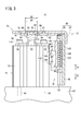
- FIG. 3 is an overall schematic side view of the cylinder with a guide mechanism according to the first embodiment.
- FIG. 4 is a schematic exploded side view of the guide mechanism constituting the cylinder with the guide mechanism according to the first embodiment.
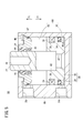
- FIG. 5 is a schematic cross-sectional side view of a cylinder constituting the cylinder with a guide mechanism according to the first embodiment.
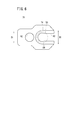
- FIG. 6 is a schematic plan view of a holding plate (holding member) constituting the guide mechanism.
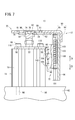
- FIG. 7 is an overall schematic side view when the piston rod, the floating bush, the holding portion, and the guide groove (guide member) of the cylinder with the guide mechanism reach the top dead center.
- FIG. 8 is an overall schematic perspective view of a cylinder with a guide mechanism according to the second embodiment of the present invention.
- FIG. 9 is an overall schematic side view of a cylinder with a guide mechanism according to the second embodiment.
- FIG. 10 is an overall schematic perspective view of a cylinder with a guide mechanism according to the third embodiment of the present invention.
- FIG. 11 is an overall schematic side view of a cylinder with a guide mechanism according to the third embodiment.
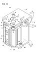
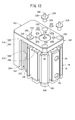
- FIG. 12 is an overall schematic perspective view of a cylinder with a guide mechanism according to the fourth embodiment.
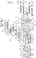
- FIG. 13 is a schematic exploded perspective view of a cylinder with a guide mechanism according to the fourth embodiment.
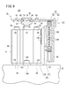
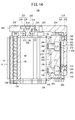
- FIG. 14 is a schematic side cross-sectional view of a cylinder with a guide mechanism according to the fourth embodiment.
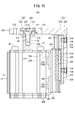
- FIG. 15 is a schematic side cross-sectional view when the holding portion in the cylinder with a guide mechanism according to the fourth embodiment is displaced.
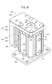
- FIG. 16 is a schematic perspective view of a flange member that can be assembled to the cylinder with a guide mechanism according to the fourth embodiment.
- FIG. 17 is an overall schematic side view showing a modified example in which a flange portion is provided in the cylinder with a guide mechanism according to the fourth embodiment.
- FIG. 18 is an overall schematic side view showing a modification in which a flange portion is provided at a position different from that in FIG.
- a cylinder guide mechanism according to the present invention will be described in detail with reference to the accompanying drawings by giving preferred embodiments in relation to a cylinder with a guide mechanism to which the guide mechanism is attached.
- the cylinder guide mechanism may be simply referred to as “guide mechanism”.
- FIG. 1 to 3 are an overall schematic perspective view, a schematic exploded perspective view, and an overall schematic side view of the cylinder 10 with a guide mechanism according to the first embodiment, respectively.
- FIG. 4 is a schematic exploded side view of the guide mechanism 12. It is.
- This cylinder 10 with a guide mechanism is configured by attaching a guide mechanism 12 to a cylinder 14.
- the cylinder 14 will be described first. As shown in FIG. 5, the cylinder 14 is connected to the tube 16, the piston 20 inserted into the piston sliding hole 18 formed in the tube 16, and the piston 20. And a piston rod 22. The opening of the piston sliding hole 18 is closed by a collar 24, and the tip end of the piston rod 22 is exposed to the outside of the tube 16 through a through hole 26 formed at a substantially central portion of the collar 24.
- the side on which the piston rod 22 is exposed is referred to as the upper side, and the opposite side is referred to as the lower side.
- the end or end surface of the tube 16 that is closed by the collar 24 and the tip of the piston rod 22 is exposed is the upper end or upper end surface
- the closed surface that is the back surface opposite to the upper end surface is It is the lower end surface
- the piston 20 has a substantially equal-diameter disk portion 28 and a small-diameter columnar convex portion 30 protruding from the lower end surface of the disk portion 28.
- the lower end surface of the cylindrical protrusion 30 is seated on the inner wall of the lower end surface of the tube 16.
- a slight clearance (first chamber 32) is formed between the inner wall of the lower end surface of the tube 16 and the lower end surface of the disk portion 28.
- annular recess 34 is formed in the vicinity of the lower end surface of the disk portion 28 so as to circulate around the side wall so as to be directed inward in the diameter direction.
- An annular piston packing 36 for sealing between the side wall of the piston 20 and the inner wall of the tube 16 is attached to the annular recess 34.
- a plurality of receiving holes 38 are formed in the vicinity of the upper end surface of the disk portion 28 so as to be recessed inward in the diameter direction.
- a permanent magnet 39 is accommodated in each accommodation hole 38.
- a bolt insertion hole 40 and a rod insertion hole 42 connected to the bolt insertion hole 40 are formed substantially at the center of the piston 20.
- the bolt insertion hole 40 and the rod insertion hole 42 extend along the thickness direction of the piston 20, the bolt insertion hole 40 is formed from the lower end surface of the piston 20 to a substantially middle part in the thickness direction, and the rod insertion hole 42 is It is formed from the substantially middle part in the thickness direction to the upper end surface of the piston 20.
- the lower end of the piston rod 22 is inserted into the rod insertion hole 42.
- a bolt hole (not shown) is formed in the lower end portion of the piston rod 22, and a bolt (not shown) passed through the bolt insertion hole 40 is screwed into the bolt hole, so that the piston rod 22 and the piston 20 are mutually connected. Connected.
- the upper end portion of the piston rod 22 is passed through the through hole 26 of the collar 24.
- a bush 43 and a rod packing 44 are interposed between the inner wall of the through hole 26 and the side wall of the piston rod 22.
- the piston rod 22 is displaced while being in sliding contact with the bush 43 and the rod packing 44.
- the collar 24 is locked to the tube 16 via an annular locking member 46, and is thus positioned and fixed at a position where the opening of the piston sliding hole 18 is closed.
- a gasket 47 is attached to the side wall of the collar 24 to seal between the side wall and the inner wall of the piston sliding hole 18.
- a bottomed connection hole 48 is formed at the upper end of the piston rod 22.
- a screw portion (not shown) is formed on the inner peripheral wall of the connection hole 48.
- the lower end portion of the floating bush 50 (see FIGS. 1 to 4) constituting the guide mechanism 12 is screwed into the screw portion.
- the piston sliding hole 18 is divided into a first chamber 32 and a second chamber 52 with the disk portion 28 of the piston 20 as a boundary. That is, the first chamber 32 is between the inner wall of the lower end surface of the tube 16 and the lower end surface of the disk portion 28, and the second chamber 52 is between the upper end surface of the disk portion 28 and the lower end surface of the collar 24. Movement of the working fluid from the first chamber 32 to the second chamber 52 or in the opposite direction is prevented by the piston packing 36. Further, the movement of the working fluid from the second chamber 52 to the atmosphere or in the opposite direction is prevented by the rod packing 44.
- the tube 16 is formed with a first port 54 communicating with the first chamber 32 and a second port 56 communicating with the second chamber 52.
- a working fluid for example, air
- the working fluid is supplied to the first chamber 32 and the second chamber 52 through the first port 54 and the second port 56, or the working fluid is discharged from the first chamber 32 and the second chamber 52. Is done.
- tie rod insertion holes 58 connection member insertion holes
- Each tie rod insertion hole 58 is passed through a long tie rod 60 that is a connecting member.
- Each tie rod 60 is screwed into a screwing hole 64 (see FIG. 3) of a predetermined attached member 62 (predetermined member) disposed below the tube 16, so that the cylinder 10 with a guide mechanism is covered. It is positioned and fixed with respect to the mounting member 62. Along with this, the tube 16 is connected to the mounted member 62.
- the guide mechanism 12 includes the floating bush 50, a holding portion 70 that holds the floating bush 50, and a linear guide 72 (guide mechanism) held by the holding portion 70.
- the floating bush 50 is formed as a screw portion having a small diameter at the lower end. This threaded portion is inserted into a connecting hole 48 formed in the upper end portion of the piston rod 22 and screwed into a threaded portion formed in the inner peripheral wall of the connecting hole 48. Therefore, when the floating bush 50 is connected to the piston rod 22, the piston rod 22 and the floating bush 50 extend along the same axis.
- annular groove 74 (circulating groove) is formed that circulates inward in the diametrical direction so as to go around the side wall.
- the annular groove 74 serves as a first engaging portion for holding the floating bush 50 in the holding portion 70.
- a bottomed screw hole 76 for inserting a screwdriver, a wrench or the like is recessed in the upper end surface of the floating bush 50.
- the holding unit 70 includes a holding plate 78 (holding member) and an L-shaped plate 80 (work conveying member) that holds the holding plate 78.
- the holding plate 78 therein has a substantially Y shape as shown in FIG. 6, and therefore, a U-shaped groove 82 is formed at the front end branched into two branches.
- the U-shaped groove 82 is inserted into the upper end of the floating bush 50 where the annular groove 74 is formed.
- the width direction dimension W1 of the opening of the U-shaped groove 82 is set smaller than the diameter of the upper end portion of the floating bush 50. For this reason, the lower end surface side wall of the annular groove 74 of the floating bush 50 contacts the holding plate 78, and as a result, the floating bush 50 is blocked. Thereby, the floating bush 50 is prevented from coming off from the U-shaped groove 82. That is, a portion in the vicinity of the U-shaped groove 82 is an insertion portion (second engagement portion) that is inserted into the annular groove 74 and engages with the annular groove 74.
- the widthwise dimension W1 of the U-shaped groove 82 is slightly larger than the diameter D1 of the portion of the floating bush 50 corresponding to the bottom wall of the annular groove 74. Therefore, a play 84 having a predetermined interval is formed between the bottom wall of the annular groove 74 (first engaging portion) and the inner wall (second engaging portion) of the U-shaped groove 82.
- the holding plate 78 is joined to the L-shaped plate 80 (see FIGS. 1 to 3) by welding, for example, and is thereby held by the L-shaped plate 80.
- the floating bush 50 is held on the L-shaped plate 80 via the holding plate 78.
- the holding plate 78 has a bifurcated front end directed toward the first port 54 and the second port 56 and a plate-like rear end facing the linear guide 72.
- Bush insertion holes 86 are formed through the flat ceiling wall 85 of the L-shaped plate 80 in the thickness direction. The upper end portion of the floating bush 50 is inserted into the bush insertion hole 86. The upper end surface of the floating bush 50 and the upper end surface of the L-shaped plate 80 are substantially flush.
- the diameter D2 of the bush insertion hole 86 is slightly larger than the diameter D3 of the upper end surface of the floating bush 50. Therefore, a play 88 having a predetermined interval is formed between the inner wall of the bush insertion hole 86 and the side wall of the upper end surface of the floating bush 50.
- the ceiling wall 85 further includes four tie rod passage holes 90 (connection member passage holes) for allowing the tie rod 60 to pass therethrough and two workpiece support holes.
- 91 is formed penetrating along the thickness direction.
- the four tie rod passage holes 90 are located at a position corresponding to the apex of the square and face the tie rod insertion hole 58 formed in the tube 16.
- the workpiece support hole 91 is located closer to the bush insertion hole 86 than the tie rod passage hole 90 and is positioned so as to sandwich the bush insertion hole 86.
- Work support hole 91 is for attaching a predetermined work (not shown). That is, for example, when a screw hole is formed in the workpiece, a bolt is passed from the lower end surface side of the ceiling wall portion 85 of the L-shaped plate 80 to the workpiece support hole 91 and screwed into the screw hole. Good.
- the holding plate 78 has a shape and dimensions that do not block the workpiece support hole 91.
- a through hole 92 may be formed in the holding plate 78 so as to continue to the work support hole 91.
- a stepped pin may be inserted into the workpiece supporting hole 91 to support the workpiece with the stepped pin.
- a guide member 96 that constitutes a linear guide 72 as a guide mechanism is welded to the hanging wall portion 94 that is bent from the ceiling wall portion 85 of the L-shaped plate 80 and is substantially suspended.
- the linear guide 72 is held by the holding unit 70.
- the holding plate 78 is also indirectly supported by the guide member 96. That is, the holding part 70 is supported by the guide member 96.
- the linear guide 72 is of a so-called circulation ball type. That is, the slider 98 as the displacement member is displaced relative to the guide member 96 by circulating a plurality of balls 100 in the guide groove 101 formed in the guide member 96. At this time, it goes without saying that the slider 98 relatively moves along the guide groove 101.
- the L-shaped bracket 102 as a bracket is attached to the slider 98 and the tube 16. That is, the L-shaped bracket 102 has a ceiling wall portion 104 (flat portion) and a hanging wall portion 106 (flat portion) bent so as to be substantially suspended from the ceiling wall portion 104, and the ceiling wall portion.
- An elbow shape in which the crossing angle between 104 and the hanging wall portion 106 is approximately 90 ° is formed. In other words, the ceiling wall part 104 and the hanging wall part 106 are connected via the bent part.
- the hanging wall portion 106 is attached (supported) to the slider 98 by a bolt 108.
- four tie rod dam holes 110 are formed in the ceiling wall portion 104, and the tube 16 is attached to the ceiling wall portion 104 by the tie rod 60 whose head is dammed in each tie rod dam hole 110. Being supported (supported).
- the cylinder 10 with a guide mechanism according to the first embodiment is basically configured as described above. Next, with respect to the effects thereof, the operation of attaching the guide mechanism 12 to the cylinder 14 or the cylinder 14 is performed. This will be described in relation to the operation.
- the floating bush 50 constituting the guide mechanism 12 assembled in advance. Is inserted into the connecting hole 48 of the piston rod 22. Thereafter, the floating bush 50 is rotated via a screwdriver or a wrench inserted into the screw hole 76 of the floating bush 50. Thereby, the screw portion of the floating bush 50 is screwed into the screw portion of the connecting hole 48.
- the lower end surface of the tube 16 is brought into contact with a predetermined portion of the attached member 62.
- the position of the tie rod insertion hole 58 is aligned with the position of the screw hole 64 formed in the attached member 62. That is, the tie rod insertion hole 58 is connected to the screw hole 64.
- the lower end surface of the ceiling wall portion 104 of the L-shaped bracket 102 of the guide mechanism 12 is brought into contact with the upper end surface of the tube 16 such that the tie rod blocking hole 110 is continuous with the tie rod insertion hole 58 of the tube 16. .
- the thread portion of the tie rod 60 is passed through the tie rod passage hole 90, the tie rod blocking hole 110 of the L-shaped plate 80, and the tie rod insertion hole 58 of the tube 16, and screwed into the screw hole 64. Since the diameter of the head of the tie rod 60 is smaller than the diameter of the tie rod passage hole 90, it is easy for the tie rod 60 to pass through the tie rod passage hole 90.
- the head portion of the tie rod 60 is dammed by a portion near the opening of the tie rod dam hole 110.
- the tie rod 60 connects the L-shaped bracket 102 to the tube 16 and connects the tube 16 to the mounted member 62.
- the guide mechanism 12 is attached to the cylinder 14 and the cylinder 14 is positioned and fixed to the attached member 62.
- the floating bush 50 is attached (connected) to the piston rod 22 so that the floating bush 50 extends on the same axis with respect to the piston rod 22, and the slider 98 is attached. It is attached to the tube 16 via an L-shaped bracket 102. For this reason, what is called retrofit installation attached to the existing cylinder 14 is easy.
- a play 84 is formed between the inner wall of the U-shaped groove 82 of the holding plate 78 and the bottom wall of the annular groove 74 of the floating bush 50, and the bush insertion hole of the L-shaped plate 80.
- a play 88 is formed between the inner wall 86 and the side wall of the upper end of the floating bush 50.
- the floating bush 50 may be displaced relative to the holding portion 70 within the range of the play 84, 88. Is possible. That is, the floating bush 50 is connected to the piston rod 22 so that the axial center of the floating bush 50 coincides with the axial center of the piston rod 22 while maintaining the state where the floating bush 50 is held by the holding plate 78 and thus the holding portion 70. can do.
- the floating bush 50 can be attached to the piston rod 22.
- a workpiece (not shown) is attached to the L-shaped plate 80 via a bolt or the like passed through the workpiece support hole 91. Thereby, a workpiece
- work is supported by the cylinder 10 with a guide mechanism.
- the cylinder 10 with a guide mechanism operates as follows. That is, when the piston rod 22 and the floating bush 50 are located at the bottom dead center, the working fluid (for example, air) is supplied to the first chamber 32 from the first port 54 shown in FIG. The piston 20 receives the pressure of the working fluid supplied to the first chamber 32. As a result, the piston 20 and the piston rod 22 rise. At this time, the working fluid stored in the second chamber 52 is discharged from the second port 56.
- the working fluid for example, air
- the floating bush 50 rises. Since the floating bush 50 is held by the holding plate 78 and the L-shaped plate 80 holding the holding plate 78 also holds the guide member 96, the floating portion 50 and the holding portion 70 The guide member 96 is raised. At this time, since the ball 100 circulates in the guide groove 101, the slider 98 maintains the original position. Accordingly, the slider 98 is lowered relative to the guide member 96.
- the working fluid for example, air
- the piston 20 descends in response to the pressure of the working fluid supplied to the second chamber 52.
- the working fluid stored in the first chamber 32 is discharged from the first port 54.
- the piston rod 22 and the floating bush 50 are lowered. Along with this, the holding portion 70 and the guide member 96 are also lowered. Also at this time, since the ball 100 circulates in the guide groove 101, the slider 98 maintains the original position. Accordingly, the slider 98 rises relative to the guide member 96.
- the lower end surface of the ceiling wall portion 104 of the L-shaped bracket 102 is brought into contact with the upper end surface of the tube 16, and the L-shaped bracket 102 and the tube 16 are connected by the tie rod 60.
- the flat portion may be brought into contact with the lower end surface of the tube 16.
- FIG. 8 is an overall schematic perspective view of the cylinder 120 with a guide mechanism according to the second embodiment
- FIG. 9 is an overall schematic side view thereof.
- the L-shaped bracket 124 includes a bottom wall portion 126 (flat portion) and a vertical wall portion 127 (flat portion) that rises substantially vertically from the bottom wall portion 126. And have.
- the vertical wall portion 127 is attached to the slider 98 via a bolt 108 in the same manner as the hanging wall portion 106 of the L-shaped bracket 102 in the guide mechanism-equipped cylinder 10 according to the first embodiment.
- tie rod insertion holes 128 are formed penetrating along the thickness direction (vertical direction).
- two tab portions 130 protrude from the bottom wall portion 126 at symmetrical positions.
- a bolt insertion hole 132 is formed through each tab portion 130.
- the mounted member 62 is formed with a screw hole 136 for screwing the bolt 134 in addition to the screw hole 64 for screwing the tie rod 60.
- the bottom wall 126 that wraps around the lower end surface of the tube 16 has the tie rod 60 screwed into the screwing hole 64 and the screw part of the bolt 134 passed through the bolt insertion hole 132 screwed into the screwing hole 136. As a result, positioning and fixing are performed while being interposed between the mounted member 62 and the tube 16.
- the guide mechanism 122 includes a thread portion of the tie rod 60 that has passed through the tie rod passage hole 90 of the L-shaped plate 80, a tie rod insertion hole 58 of the tube 16, and a tie rod insertion hole of the L-shaped bracket 124. After being further passed through 128, it is attached to the cylinder 14 by being screwed into the screw hole 64. Further, the cylinder 120 with a guide mechanism is attached to the attached member 62 by screwing the tie rod 60 and the bolt 134.
- the diameter of the head of the tie rod 60 is larger than the diameter of the tie rod insertion hole 58 of the tube 16. For this reason, the tie rod 60 is blocked by the tube 16.
- a screwdriver or a wrench is inserted from the tie rod passage hole 90 of the L-shaped plate 80, and the tie rod 60 is screwed to be loosened. Good.
- the tie rod 60 may be removed by passing through the tie rod passage hole 90 or may be inserted into the tie rod insertion hole 58 of the tube 16.
- a screwdriver or a wrench is inserted into the screw hole 76 of the floating bush 50, and the floating bush 50 is screwed to relax from the piston rod 22. As described above, the cylinder 14 is released from the restraint of the guide mechanism 122.
- the cylinder 14 is taken out from between the bottom wall portion 126 of the L-shaped bracket 124 and the ceiling wall portion 85 of the L-shaped plate 80, the cylinder 14 is exposed to the outside of the guide mechanism 122. That is, the cylinder 14 is removed from the guide mechanism 122.
- the cylinder 14 is inserted between the bottom wall portion 126 of the L-shaped bracket 124 and the ceiling wall portion 85 of the L-shaped plate 80, and the tie rod 60 is screwed into the screwing hole 64. Then, the cylinder 14 is reattached to the guide mechanism 122. During the maintenance, the spare cylinder 14 may be attached to the guide mechanism 122 to carry the workpiece.
- the guide mechanism 122 is attached to the attached member 62 by the bolt 134 that is screwed into the screwing hole 136 of the attached member 62 to position and fix the L-shaped bracket 124. Remains attached. That is, when removing the cylinder 14 from the guide mechanism 122 and when reattaching it to the guide mechanism 122, it is not particularly necessary to remove the guide mechanism 122 from the attached member 62. For this reason, both the removal operation and the reattachment operation are simple.
- FIG. 10 is an overall schematic perspective view of a cylinder 140 with a guide mechanism according to the third embodiment
- FIG. 11 is an overall schematic side view thereof.
- the guide mechanism 142 constituting the cylinder 140 with a guide mechanism has a first L-shaped bracket 144 and a second L-shaped bracket 146.
- the first L-shaped bracket 144 is formed in substantially the same manner as the L-shaped bracket 124, and has a first bottom wall portion 148 (flat portion) and a long length that rises substantially vertically from the first bottom wall portion 148.
- First vertical wall portion 150 flat portion
- four tie rod insertion holes 128 are formed penetrating along the thickness direction (vertical direction).
- two wide portions 152 are formed to protrude from the first bottom wall portion 148 at symmetrical positions.
- Bolt insertion holes 154 are formed through the wide portions 152.
- One first vertical wall 150 is attached to the slider 98 via a bolt 108.
- a second L-shaped bracket 146 is positioned and fixed to the first vertical wall 150.
- the second L-shaped bracket 146 includes a second bottom wall portion 156 (flat portion) and a short second vertical wall portion 158 (flat portion) rising substantially vertically from the second bottom wall portion 156. And have.
- the first vertical wall portion 150 and the second vertical wall portion 158 are formed with insertion holes, respectively. When the second vertical wall portion 158 contacts the first vertical wall portion 150, the insertion holes are formed with each other. overlap.
- Bolts 160 are passed through these insertion holes, and nuts 162 are screwed onto the bolts 160.
- the second L-shaped bracket 146 is connected to the first L-shaped bracket 144.
- the second bottom wall portion 156 covers the upper end surface of the tube 16 similarly to the ceiling wall portion 104 of the L-shaped bracket 102 in the first embodiment.
- Four tie rod dam holes 110 are formed in the second bottom wall portion 156.
- the threaded portion of the tie rod 60 that has passed through the tie rod passage hole 90 of the L-shaped plate 80 is a tie rod blocking hole 110 formed in the second bottom wall portion 156 of the second L-shaped bracket 146, a tube 16 and the tie rod insertion hole 128 formed in the first bottom wall portion 148 of the first L-shaped bracket 144, and screwed into the screwing hole 64 formed in the attached member 62. Is done. Accordingly, the guide mechanism 142 is attached to the cylinder 14 and the guide mechanism-equipped cylinder 140 is attached to the attached member 62.
- the diameter of the head of the tie rod 60 is larger than the diameter of the tie rod dam hole 110. For this reason, the tie rod 60 is blocked by the second bottom wall portion 156 of the second L-shaped bracket 146.
- the attached member 62 is formed with a screwing hole 166 for screwing the bolt 164 passed through the bolt insertion hole 154 of the first bottom wall portion 148.
- the tie rod 60 is screwed into the screwing hole 64, and the screw portion of the bolt 164 passed through the bolt insertion hole 154 is screwed into the screwing hole 166.
- the holding plate 168 that holds the floating bush 50 is a small flat plate-shaped member in which a U-shaped groove 82 is formed.
- a screwdriver or a wrench is inserted from the tie rod passage hole 90 of the L-shaped plate 80, and the tie rod 60 is screwed to be loosened. Good.
- the tie rod 60 may be removed by passing through the tie rod passage hole 90 or may remain inserted in the tie rod blocking hole 110 of the second L-shaped bracket 146.
- the guide mechanism 142 is attached to the attached member by the bolt 164 that is screwed into the screwing hole 166 of the attached member 62 and positions and fixes the first L-shaped bracket 144. 62 remains attached. That is, as in the second embodiment, there is no need to remove the guide mechanism 142 from the attached member 62 when removing the cylinder 14 from the guide mechanism 142 and when reattaching the cylinder 14 to the guide mechanism 142. For this reason, both the removal operation and the reattachment operation are simple.
- the operation and other operational effects of the guide mechanism-equipped cylinder 140 according to the third embodiment are the same as those of the guide mechanism-equipped cylinder 10 according to the first embodiment and the guide mechanism-equipped cylinder 120 according to the second embodiment. Description is omitted.
- a positioning member for positioning the workpiece may be inserted into the connecting member passage hole represented by the tie rod passage hole 90.
- This configuration will be described as a fourth embodiment.
- the same components as those shown in FIGS. 1 to 11 are basically assigned the same names, and detailed description thereof will be omitted.
- FIGS. 12 to 14 are an overall schematic perspective view, a schematic exploded perspective view, and a schematic side cross-sectional view, respectively, of a guide mechanism-equipped cylinder 180 according to the fourth embodiment.
- the cylinder 180 with a guide mechanism is configured by attaching a guide mechanism 182 to the cylinder 14.
- a flat plate 184 and an L-shaped plate 186 are disposed on the lower end surface side of the tube 16.
- the flat plate 184 and the L-shaped plate 186 are respectively formed with a tie rod screw hole 188 and a first tie rod passage hole 190 that overlap the tie rod insertion hole 58 of the tube 16.
- the tie rod 60 passed through the first tie rod passage hole 190 is screwed into the tie rod screw hole 188.
- the tube 16 is connected to the flat plate 184, and the L-shaped plate 186 is sandwiched between the tube 16 and the flat plate 184. That is, in the fourth embodiment, the flat plate 184 is a “predetermined member”.
- Through holes 192 and 194 are formed between adjacent tie rod screw holes 188 and 188 and between the first tie rod passage holes 190 and 190, respectively.
- the tie rod screw hole 188 and the through hole 192 penetrate along the thickness direction of the flat plate 184, and the first tie rod passage hole 190 and the through hole 194 penetrate along the thickness direction of the L-shaped plate 186.
- the position of the tie rod screw hole 188 corresponds to the position of the first tie rod passage hole 190, and the position of the through hole 192 corresponds to the through hole 194.
- the vertical wall 196 of the L-shaped plate 186 is formed with a bolt receiving hole 198 in which a screw portion is engraved.
- the guide mechanism 182 includes a floating bush 200, a holding portion 202 that holds the floating bush 200, and a linear guide 204 (guide mechanism) that guides the floating bush 200 through the holding portion 202.
- the floating bush 200 has a shaft portion 206, a damming portion 208, and a head portion 210, and has a large diameter in this order.
- the shaft portion 206 is inserted into a connecting hole 48 formed in the upper end portion of the piston rod 22, and a screw portion formed on the side wall of the shaft portion 206 is screwed into a screw portion in the connecting hole 48. .
- annular convex portion 212 is formed to protrude outward in the diametrical direction at an upper portion adjacent to the damming portion 208.
- the annular convex portion 212 is set to have a smaller diameter than the damming portion 208.
- a bottomed screw hole 214 for inserting a screwdriver, a wrench or the like is formed in a recessed manner on the upper end surface of the head portion 210 that continues above the damming portion 208.
- the holding unit 202 includes an L-shaped arm member 216 (work conveying member) for conveying a workpiece, and a holding ring 218 (for holding the floating bush 200 on the L-shaped arm member 216). Holding member).
- the shaft portion 206 of the floating bush 200 is passed through the holding ring 218 therein.
- the inner diameter of the holding ring 218 is set substantially equal to the maximum diameter of the annular convex portion 212.
- the thickness of the retaining ring 218 is larger than the thickness of the annular convex portion 212. Therefore, the annular convex portion 212 abuts only on a part of the inner wall of the holding ring 218. In other words, most of the inner wall of the retaining ring 218 is separated from the shaft portion 206.
- Bush insertion holes 222 are formed through the flat ceiling wall 220 of the L-shaped arm member 216 in the thickness direction.
- An annular step 224 is formed in the bush insertion hole 222.
- the bush insertion hole 222 includes a small diameter hole 226 and a large diameter hole 228.
- the small-diameter hole 226 has a larger diameter than the shaft portion 206 and the blocking portion 208, and a smaller diameter than the head portion 210.
- the large diameter hole 228 has a larger diameter than the head 210.
- the shaft portion 206 and the damming portion 208 of the floating bush 200 are passed through the small-diameter hole 226, and the shaft portion 206 is screwed into the connecting hole 48 as described above.
- the holding ring 218 is sandwiched between the top surface of the piston rod 22 and the lower end surface of the damming portion 208.
- the floating bush 200 is prevented from coming off from the bush insertion hole 222. That is, the floating bush 200 is held by the L-shaped arm member 216 by the holding ring 218.
- the side wall of the blocking portion 208 is separated from the inner wall of the small diameter hole 226.
- the head 210 of the floating bush 200 is separated from both the inner wall of the large diameter hole 228 and the annular step 224. That is, a predetermined play is formed between the floating bush 200 and the L-shaped arm member 216.
- the floating bush 200 is not restrained by the L-shaped arm member 216. After all, even in this case, the floating bush 200 is in a floating support state in which the inside of the bush insertion hole 222 can be relatively displaced within the range of play.
- the upper end surface of the head 210 is accommodated in the bush insertion hole 222. That is, the upper end surface of the head 210 is lower than the upper end surface of the L-shaped arm member 216.
- the ceiling wall portion 220 further includes four second tie rod passage holes 230 (connection member passage holes) for allowing the tie rod 60 to pass therethrough and four workpiece support holes 232 along the thickness direction. It is formed through.
- the four second tie rod passage holes 230 are located at locations corresponding to the apexes of the square and face the tie rod insertion holes 58 formed in the tube 16.
- the workpiece support hole 232 is closer to the bush insertion hole 222 than the second tie rod passage hole 230 and is located between the adjacent bush insertion holes 230 and 230.
- Stepped pin 234 (positioning member) is inserted into second tie rod passage hole 230. That is, the stepped pin 234 includes a fixing insertion portion 236 having a columnar shape or a cylindrical shape, a stopper portion 238 having a diameter larger than that of the second tie rod passage hole 230, and a positioning insertion portion for positioning the workpiece. 240 is connected in a straight line. The fixing insertion portion 236 is inserted into the second tie rod passage hole 230, and the exposed positioning insertion portion 240 is inserted into a predetermined positioning hole formed in the workpiece.
- One work support hole 232 is for attaching the work to the L-shaped arm member 216. That is, for example, when a screw hole is formed in the workpiece, a bolt body is passed through the workpiece support hole 232 from the lower end surface side of the ceiling wall portion 220 of the L-shaped arm member 216, and the screw hole is inserted into the screw hole. It only has to be screwed together.
- a stepped pin may be inserted to support the workpiece with the stepped pin.
- a bottomed notch portion 244 having a shape like a long hole divided into two is formed in a hanging wall portion 242 that is bent from the ceiling wall portion 220 of the L-shaped arm member 216 and is substantially suspended. Also, a screw hole 246 is formed in the hanging wall portion 242, and the guide member 250 constituting the linear guide 204 as a guide mechanism is connected to the hanging wall portion via a screw 248 screwed into the screw hole 246. 242. By this connection, the guide member 250 is held by the L-shaped arm member 216. The guide member 250 is disposed so that the bottomed notch 244 is exposed.
- the guide member 250 is formed with a screw insertion hole 252 for passing the screw 248 and a rivet hole 254.
- the rivet 256 passed through the rivet hole 254 is prevented from coming out of the rivet hole 254 by crushing the shaft portion.
- the crushed shaft portion enters the bottomed cutout portion 244.
- the floating bush 200 is held by the L-shaped arm member 216 via the holding ring 218. For this reason, the floating bush 200 is also indirectly supported by the guide member 250.
- a guide groove 260 is formed in the guide member 250, and a ball groove 264 is formed in the slider 262 as a displacement member.
- the slider 262 is displaced relative to the guide member 250 when the plurality of balls 266 slide in the guide groove 260 and the ball groove 264.
- the slider 262 is formed with bolt receiving holes 270 and 272 through which the connecting bolt 268 is passed.
- the connecting bolt 268 passed through the bolt receiving hole 270 is screwed into the bolt receiving hole 198 of the L-shaped plate 186.
- the connecting bolt 268 passed through the bolt receiving hole 272 is screwed into a bolt receiving hole 276 of an L-shaped bracket 274 (described later).
- the L-shaped plate 186 and the L-shaped bracket 274 are connected to the slider 262.
- the slider 262 is formed with a semicircular notch 277 for avoiding interference of the rivet 256.
- the slider 262 is covered with a ball cover 278 having a side end surface bent at approximately 90 °.
- a plurality of holding windows 280 are formed on the side end surfaces, and each ball 266 slides on the guide groove 260 and the ball groove 264 while being inserted into the holding window 280.
- a lower stopper member 282 and an upper stopper member 284 are welded to the lower end surface and the upper end surface of the slider 262, respectively.
- the lower stopper member 282 and the upper stopper member 284 restrict the displacement of the ball cover 278.
- the slider 262 and the tube 16 are connected via an L-shaped bracket 274.
- the L-shaped bracket 274 has a ceiling wall portion 286 (flat portion) and a hanging wall portion 288 (flat portion) substantially suspended from the ceiling wall portion 286, and the ceiling wall portion 286 and the hanging wall portion 288.
- An elbow shape having an intersection angle of approximately 90 ° is formed.
- the hanging wall portion 288 is attached (supported) to the slider 262 by the connection bolt 268 being screwed into the bolt receiving hole 276 as described above.
- four tie rod dam holes 290 are formed in the ceiling wall portion 286, and the tube 16 is attached to the ceiling wall portion 286 by the tie rod 60 whose head is dammed in each tie rod dam hole 290. Being supported (supported).
- the cylinder with guide mechanism 180 according to the fourth embodiment is basically configured as described above. Next, the operation and effect will be described.
- the slider 262 is connected to the tube via the L-shaped plate 186 and the L-shaped bracket 274 using a connecting bolt 268.
- the whole connecting bolt 268 that is screwed is accommodated in the bolt accommodating holes 270 and 272.
- the slider 262 is covered with a ball cover 278 holding the ball 266 on the holding window 280, and the ball cover 278 is covered with the guide member 250.
- the ball 266 in the holding window 280 is inserted into the ball groove 264 and the guide groove 260.
- the lower stopper member 282 and the upper stopper member 284 are joined to the slider 262.
- the shaft portion of the rivet 256 that is passed through the rivet hole 254 in advance and exposed on the back surface (the end surface facing the hanging wall portion 242) of the guide member 250 is crushed.
- the screw 248 passed through the screw insertion hole 252 is screwed into the screw hole 246.
- the linear guide 204 is held by the L-shaped arm member 216.
- the crushed shaft portion of the rivet 256 enters the bottomed cutout portion 244 of the L-shaped arm member 216.
- the shaft portion 206 of the floating bush 200 is passed through the small diameter hole 226 of the bush insertion hole 222 and the holding ring 218 and inserted into the connection hole 48 of the piston rod 22. Thereafter, the floating bush 200 is rotated via a screwdriver or a wrench inserted into the screw hole 214 of the floating bush 200. As a result, the screw portion of the floating bush 200 is screwed into the screw portion of the connecting hole 48.
- the holding ring 218 is sandwiched between the top surface of the piston rod 22 and the lower end surface of the damming portion 208 of the floating bush 200.
- the retaining ring 218 supports the floating bush 200, so that the floating bush 200 is prevented from coming off from the bush insertion hole 222. That is, the floating bush 200 is held by the L-shaped arm member 216 via the holding ring 218.
- the lower end surface of the tube is brought into contact with a predetermined portion of the L-shaped plate 186 on the flat plate 184.
- the position of the tie rod insertion hole 58 of the tube 16 is aligned with the positions of the first tie rod passage hole 190 and the tie rod screwing hole 188. That is, the first tie rod passage hole 190 and the tie rod insertion hole 58 are connected to the tie rod screwing hole 188.
- the L-shaped bracket 274 is arranged so that the tie rod dam hole 290 overlaps the tie rod insertion hole 58. Further, the thread portion of the tie rod 60 is passed through the second tie rod passage hole 230, the tie rod blocking hole 290, and the tie rod insertion hole 58 of the L-shaped arm member 216 and screwed into the tie rod screw hole 188. Since the diameter of the head of the tie rod 60 is smaller than the diameter of the second tie rod passage hole 230, it is easy for the tie rod 60 to pass through the second tie rod passage hole 230.
- the head portion of the tie rod 60 is dammed by a portion in the vicinity of the opening of the tie rod dam hole 290.
- the tie rod 60 connects the L-shaped bracket 274 to the tube 16 and connects the tube 16 to the flat plate 184 and the L-shaped plate 186.
- the guide mechanism 182 is attached to the cylinder 14 to form the guide mechanism-equipped cylinder 180.
- a stepped pin may be used. That is, one end of the stepped pin may be inserted into the through holes 192 and 194 and the other end may be inserted into the positioning hole of a predetermined member.
- the side wall of the blocking portion 208 of the floating bush 200 is separated from the inner wall of the small diameter hole 226, and the head 210 is separated from both the inner wall of the large diameter hole 228 and the annular step 224. ing. That is, a play is formed between the floating bush 200 and the L-shaped arm member 216. Therefore, the floating bush 200 can be displaced relative to the holding portion 202 within the range of play.
- the floating bush 200 is maintained while being held by the holding ring 218 and eventually the holding portion 202. It can be connected to the piston rod 22 so that its axis coincides with the axis of the piston rod 22.
- the fixing insertion portion 236 of the stepped pin 234 is inserted into the second tie rod passage hole 230.
- the stepped pin 234 is positioned by the stopper portion 238 coming into contact with the ceiling wall portion 220, and is exposed so that the positioning insertion portion 240 protrudes.
- a workpiece (not shown) is held by the L-shaped arm member 216 via a bolt or a stepped pin passed through the workpiece supporting hole 232. Thereby, a workpiece
- work is supported by the cylinder 180 with a guide mechanism.
- the cylinder with guide mechanism 180 operates according to the cylinder 10 with guide mechanism. That is, when the piston rod 22 and the floating bush 200 are located at the bottom dead center, the working fluid (for example, air) is supplied to the first chamber 32 from the first port 54 shown in FIG. The piston 20 receives the pressure of the working fluid supplied to the first chamber 32. As a result, the piston 20 and the piston rod 22 rise. At this time, the working fluid stored in the second chamber 52 is discharged from the second port 56.
- the working fluid for example, air
- the floating bush 200 rises.
- the floating bush 200 is held by the holding ring 218, and the L-shaped arm member 216 holding the holding ring 218 holds the guide member 250.
- the guide member 250 is raised.
- the slider 262 maintains the original position. Accordingly, the slider 262 descends relative to the guide member 250.
- the working fluid for example, air
- the piston 20 descends in response to the pressure of the working fluid supplied to the second chamber 52.
- the working fluid stored in the first chamber 32 is discharged from the first port 54.
- the guide member 250 comes into contact with the lower stopper member 282, and the curved ceiling wall in the bottomed cutout portion 244 of the L-shaped arm member 216 comes into contact with the crushed shaft portion of the rivet 256. Accordingly, further displacement of the guide member 250 is restricted. That is, the piston rod 22, the floating bush 200, the holding portion 202, and the guide member 250 return to the positions shown in FIG. 14 and reach the bottom dead center. When returning the floating bush 200 and the piston rod 22 from the top dead center to the bottom dead center, a workpiece different from the above may be supported and conveyed.
- the non-rotation accuracy is improved for the same reason as in the first embodiment. That is, also in the fourth embodiment, the same operational effects as those in the first to third embodiments can be obtained.
- the flange member 300 shown in FIG. 16 may be incorporated in the cylinder 180 with a guide mechanism.
- the flange member 300 may be interposed between the L-shaped bracket 274 and the L-shaped arm member 216 as shown in FIG. 17, and the tie rod 60 may be passed through, or the flat plate 184 as shown in FIG. Alternatively, it may be used.
- the guide mechanism-equipped cylinder 180 can be attached to the workpiece or a predetermined member via the flange member 300. Therefore, attachment becomes easier.
- tie rod 60 may be screwed into a predetermined attached member 62 (see FIG. 3), similarly to the first embodiment, without using the flat plate 184 and the flange member 300.
- a bolt body or the like may be inserted into the second tie rod passage hole 230 instead of the stepped pin 234, thereby positioning the workpiece.
- the present invention is not particularly limited to the first to fourth embodiments described above, and various modifications can be made without departing from the gist of the present invention.
- the guide member 96 is positioned on the back side of the first port 54 and the second port 56, in other words, both the ports 54 and 56, the guide member 96,
- the guide mechanisms 12, 122, 142, and 182 are attached to the cylinder 14 so that the phase difference between them is 180 °, but the guide member 96 faces both the ports 54 and 56 (the phase difference is 0 °).
- the phase difference between the guide member 96 and the ports 54 and 56 may be 90 °.
- the guide mechanisms 12, 122, 142, and 182 can be attached to the cylinder 14 in any direction. That is, the degree of freedom of attachment is high. For this reason, the guide mechanisms 12, 122, 142, and 182 can be disposed at positions that do not interfere with predetermined portions of the attached member 62.
- the side where the piston rod 22 is exposed from the tube 16 is the upper side, and the opposite side is the lower side.
- the cylinders with guide mechanisms 10, 120, 140, 180 are actually used, There is no particular need to match the extending direction of the rod 22 and the floating bushes 50, 200 with the vertical direction.
- the cylinders with guide mechanisms 10, 120, 140, 180 may be actually used in such a posture that the piston rod 22 and the floating bushes 50, 174 extend along the horizontal direction.
- the upper and lower directions in the above description do not mean the vertical direction in actual use, and the upper and lower sides may coincide with the horizontal direction in actual use, or may be inclined with respect to the vertical direction and the horizontal direction.
- the guide mechanism-equipped cylinders 10, 120, 140, 180 may be actually used in a posture in which the upper and lower sides in the above description match the vertical upper side and the vertical lower side. It may be used in an attitude in which the upper and lower sides in FIG.
Landscapes
- Engineering & Computer Science (AREA)
- General Engineering & Computer Science (AREA)
- Mechanical Engineering (AREA)
- Physics & Mathematics (AREA)
- Fluid Mechanics (AREA)
- Actuator (AREA)
- Jigs For Machine Tools (AREA)
Abstract
Description
前記ピストンロッドの進退動作に追従して進退動作するフローティングブッシュと、
前記フローティングブッシュを保持する保持部と、
前記保持部に保持された案内部材と、前記案内部材に支持されて該案内部材に対して相対的に変位する変位部材とを有する案内機構と、
前記変位部材と前記チューブを連結するためのブラケットと、
を備えるシリンダ用ガイド機構が提供される。
また、タイロッド60の頭部の直径がタイロッド堰止孔110の直径に比して大きいため、タイロッド60の頭部がタイロッド堰止孔110の開口近傍の部位によって堰止される。これにより、タイロッド60が、L字型ブラケット102をチューブ16に連結するとともに、チューブ16を被取付部材62に連結する。以上により、ガイド機構12がシリンダ14に付設されるとともに、シリンダ14が被取付部材62に位置決め固定される。
なお、第2実施形態では、ガイド機構122は、L字型プレート80のタイロッド通過孔90を通過したタイロッド60のネジ部が、チューブ16のタイロッド挿通孔58、L字型ブラケット124のタイロッド挿通孔128にさらに通された後、螺合用穴64に螺合されることでシリンダ14に付設される。また、タイロッド60及びボルト134の螺合により、ガイド機構付シリンダ120が被取付部材62に取り付けられる。
タイロッド60の頭部の直径は、チューブ16のタイロッド挿通孔58の直径に比して大きい。このため、タイロッド60は、チューブ16によって堰止される。
タイロッド60の頭部の直径は、タイロッド堰止孔110の直径に比して大きい。このため、タイロッド60は、第2L字型ブラケット146の第2底壁部156によって堰止される。
その後、メンテナンス等を施したシリンダ14を、第1L字型ブラケット144の第1底壁部148と第2L字型ブラケット146の第2底壁部156の間に挿入し、さらに、タイロッド60を螺合用穴64に螺合すれば、シリンダ14がガイド機構142に再取り付けされるに至る。なお、メンテナンス等を施している間、予備のシリンダ14をガイド機構142に取り付けてワークの搬送を行うようにしてもよい。
堰止部208の側壁は、小径孔226の内壁から離間する。また、フローティングブッシュ200の頭部210は、大径孔228の内壁、及び環状段部224の双方から離間する。すなわち、フローティングブッシュ200とL字型アーム部材216との間には所定の遊びが形成される。
天井壁部220には、さらに、前記タイロッド60を通過させるための4個の第2タイロッド通過孔230(連結部材用通過孔)と、4個のワーク支持用孔232とが厚み方向に沿って貫通形成される。4個の第2タイロッド通過孔230は、正方形の頂点に相当する箇所に位置するとともに、チューブ16に形成されたタイロッド挿通孔58に対向する。一方、ワーク支持用孔232は、第2タイロッド通過孔230に比してブッシュ挿入孔222に近接し、且つ隣接するブッシュ挿入孔230、230同士の間に位置している。
また、タイロッド60の頭部の直径がタイロッド堰止孔290の直径に比して大きいため、タイロッド60の頭部がタイロッド堰止孔290の開口近傍の部位によって堰止される。これにより、タイロッド60が、L字型ブラケット274をチューブ16に連結するとともに、チューブ16を平型プレート184及びL字型プレート186に連結する。以上により、ガイド機構182がシリンダ14に付設されてガイド機構付シリンダ180が構成される。
ピストン20が下降することに追従し、ピストンロッド22及びフローティングブッシュ200が下降する。これに伴って、保持部202及び案内部材250も下降する。この際にも、ボール266が摺動するためにスライダ262が元の位置を保つ。従って、スライダ262は、案内部材250に対して相対的に上昇する。
また、理解を容易にするための便宜上、ピストンロッド22がチューブ16から露呈した側を上方、その反対側を下方としているが、ガイド機構付シリンダ10、120、140、180の実使用時に、ピストンロッド22及びフローティングブッシュ50、200の延在方向を鉛直方向に合致させる必要は特にない。例えば、ガイド機構付シリンダ10、120、140、180を、ピストンロッド22及びフローティングブッシュ50、174が水平方向に沿って延在するような姿勢にして実使用するようにしてもよい。
すなわち、上記の説明における上方、下方は、実使用時の鉛直方向を意味するものではなく、実使用時に上方及び下方が水平方向に一致する場合もあれば、鉛直方向及び水平方向に対して傾斜することもある。勿論、ガイド機構付シリンダ10、120、140、180を、上記の説明における上方、下方が鉛直上方、鉛直下方に合致する姿勢にして実使用するようにしてもよいし、逆に、上記の説明における上方、下方が鉛直下方、鉛直上方に合致する姿勢にして実使用するようにしてもよい。
Claims (18)
- ピストンロッド(22)がチューブ(16)に対する相対的な進退動作を行うシリンダ(14)に付設されるシリンダ用ガイド機構(12)であって、
前記ピストンロッド(22)の進退動作に追従して進退動作するフローティングブッシュ(50)と、
前記フローティングブッシュ(50)を保持する保持部(70)と、
前記保持部(70)に保持された案内部材(96)と、前記案内部材(96)に支持されて該案内部材(96)に対して相対的に変位する変位部材(98)とを有する案内機構(72)と、
前記変位部材(98)と前記チューブ(16)を連結するためのブラケット(102)と、
を備えることを特徴とするシリンダ用ガイド機構(12)。 - 請求項1記載のシリンダ用ガイド機構(12)において、前記保持部(70)は、ワークを搬送するためのワーク搬送部材(80)と、前記フローティングブッシュ(50)を前記ワーク搬送部材(80)に保持するための保持部材(78)とを有し、
前記ワーク搬送部材(80)に、前記フローティングブッシュ(50)が挿入されるブッシュ挿入孔(86)が形成され、
前記ブッシュ挿入孔(86)の内壁と前記フローティングブッシュ(50)の側壁の間に遊び(88)が生じていることを特徴とするシリンダ用ガイド機構(12)。 - 請求項2記載のシリンダ用ガイド機構(12)において、前記フローティングブッシュ(50)に第1係合部(74)が形成され、且つ前記保持部材(78)に、前記第1係合部(74)に係合する第2係合部(82)が形成され、
前記第1係合部(74)と前記第2係合部(82)との間に遊び(84)が生じていることを特徴とするシリンダ用ガイド機構(12)。 - 請求項3記載のシリンダ用ガイド機構(12)において、前記第1係合部(74)が、前記フローティングブッシュ(50)の側壁を周回する周回溝(74)であり、且つ前記第2係合部(82)が、前記周回溝(74)に挿入される挿入部(82)であることを特徴とするシリンダ用ガイド機構(12)。
- 請求項1~4のいずれか1項に記載のシリンダ用ガイド機構(12)において、前記ブラケット(102)が、2個の平坦部(104、106)が折曲部を介して連なるエルボ形状をなすものであることを特徴とするシリンダ用ガイド機構(12)。
- 請求項5記載のシリンダ用ガイド機構(12)において、前記ブラケット(102)を構成する1個の平坦部(104)が、前記チューブ(16)の、前記ピストンロッド(22)が露呈した端面、又は前記端面の裏面に当接し、且つ残余の1個の平坦部(106)が前記変位部材(98)に連結されることを特徴とするシリンダ用ガイド機構(12)。
- 請求項1~6のいずれか1項に記載のシリンダ用ガイド機構(12)において、前記保持部(70)に、前記チューブ(16)を所定の部材(62)に連結する連結部材(60)を通過させるための連結部材用通過孔(90)が形成され、
前記連結部材用通過孔(90)は、前記チューブ(16)に形成されて前記連結部材(60)が挿通される連結部材用挿通孔(58)に比して大径であることを特徴とするシリンダ用ガイド機構(12)。 - 請求項7記載のシリンダ用ガイド機構(182)において、前記連結部材用通過孔(90)に挿入されるとともにワークを位置決めする位置決め用部材(234)を有することを特徴とするシリンダ用ガイド機構(182)。
- 請求項1~8のいずれか1項に記載のシリンダ用ガイド機構(12)において、前記保持部(70)に、ワークを支持するためのワーク支持用孔(91)が形成されていることを特徴とするシリンダ用ガイド機構(12)。
- ピストンロッド(22)がチューブ(16)に対する相対的な進退動作を行うシリンダ(14)と、前記シリンダ(14)に付設されるシリンダ用ガイド機構(12)とを有するガイド機構付シリンダ(10)であって、
前記シリンダ用ガイド機構(12)は、前記ピストンロッド(22)の進退動作に追従して進退動作するフローティングブッシュ(50)と、
前記フローティングブッシュ(50)を保持する保持部(70)と、
前記保持部(70)に保持された案内部材(96)と、前記案内部材(96)に支持されて該案内部材(96)に対して相対的に変位する変位部材(98)とを有する案内機構(72)と、
前記変位部材(98)及び前記チューブ(16)に連結されたブラケット(102)と、
を備えることを特徴とするガイド機構付シリンダ(10)。 - 請求項10記載のガイド機構付シリンダ(10)において、前記保持部(70)は、ワークを搬送するためのワーク搬送部材(80)と、前記フローティングブッシュ(50)を前記ワーク搬送部材(80)に保持するための保持部材(78)とを有し、
前記ワーク搬送部材(80)に、前記フローティングブッシュ(50)が挿入されるブッシュ挿入孔(86)が形成され、
前記ブッシュ挿入孔(86)の内壁と前記フローティングブッシュ(50)の側壁の間に遊び(88)が生じていることを特徴とするガイド機構付シリンダ(10)。 - 請求項11記載のガイド機構付シリンダ(10)において、前記フローティングブッシュ(50)に第1係合部(74)が形成され、且つ前記保持部材(78)に、前記第1係合部(74)に係合する第2係合部(82)が形成され、
前記第1係合部(74)と前記第2係合部(82)との間に遊び(84)が生じていることを特徴とするガイド機構付シリンダ(10)。 - 請求項12記載のガイド機構付シリンダ(10)において、前記第1係合部(74)が、前記フローティングブッシュ(50)の側壁を周回する周回溝(74)であり、且つ前記第2係合部(82)が、前記周回溝(74)に挿入される挿入部(82)であることを特徴とするガイド機構付シリンダ(10)。
- 請求項10~13のいずれか1項に記載のガイド機構付シリンダ(10)において、前記ブラケット(102)が、2個の平坦部(104、106)が折曲部を介して連なるエルボ形状をなすものであることを特徴とするガイド機構付シリンダ(10)。
- 請求項14記載のガイド機構付シリンダ(10)において、前記ブラケット(102)を構成する1個の平坦部(104)が、前記チューブ(16)の、前記ピストンロッド(22)が露呈した端面、又は前記端面の裏面に当接し、且つ残余の1個の平坦部(106)が前記変位部材(98)に連結されることを特徴とするガイド機構付シリンダ(10)。
- 請求項10~15のいずれか1項に記載のガイド機構付シリンダ(10)において、前記保持部(70)に、前記チューブ(16)を所定の部材(62)に連結する連結部材(60)を通過させるための連結部材用通過孔(90)が形成され、且つ前記チューブ(16)に、前記連結部材(60)を挿通するための連結部材用挿通孔(58)が形成され、
前記連結部材用通過孔(90)は、前記連結部材(60)及び前記連結部材用挿通孔(58)に比して大径であることを特徴とするガイド機構付シリンダ(10)。 - 請求項16記載のガイド機構付シリンダ(10)において、前記連結部材用通過孔(90)に挿入されるとともにワークを位置決めする位置決め用部材(234)を有することを特徴とするガイド機構付シリンダ(10)。
- 請求項10~17のいずれか1項に記載のガイド機構付シリンダ(10)において、前記保持部(70)に、ワークを支持するためのワーク支持用孔(91)が形成されていることを特徴とするガイド機構付シリンダ(10)。
Priority Applications (9)
| Application Number | Priority Date | Filing Date | Title |
|---|---|---|---|
| KR1020217021588A KR102380625B1 (ko) | 2014-07-09 | 2015-06-23 | 실린더용 가이드 기구 및 가이드 기구 부착식 실린더 |
| KR1020177003665A KR20170030600A (ko) | 2014-07-09 | 2015-06-23 | 실린더용 가이드 기구 및 가이드 기구 부착식 실린더 |
| US15/322,658 US10323660B2 (en) | 2014-07-09 | 2015-06-23 | Cylinder guide mechanism and cylinder with guide mechanism |
| DE112015003184.7T DE112015003184B9 (de) | 2014-07-09 | 2015-06-23 | Zylinderführungsmechanismus und Zylinder mit Führungsmechanismus |
| RU2016151220A RU2679292C2 (ru) | 2014-07-09 | 2015-06-23 | Направляющий механизм для цилиндра и цилиндр с направляющим механизмом |
| CN201580037114.6A CN106662128B (zh) | 2014-07-09 | 2015-06-23 | 缸引导机构和具有引导机构的缸 |
| JP2016532858A JP6508541B2 (ja) | 2014-07-09 | 2015-06-23 | シリンダ用ガイド機構及びガイド機構付シリンダ |
| BR112017000177A BR112017000177A2 (pt) | 2014-07-09 | 2015-06-23 | mecanismo de guia de cilindro e cilindro com mecanismo de guia. |
| MX2017000291A MX2017000291A (es) | 2014-07-09 | 2015-06-23 | Mecanismo guia de cilindro y cilindro con mecanismo guia. |
Applications Claiming Priority (2)
| Application Number | Priority Date | Filing Date | Title |
|---|---|---|---|
| JP2014141624 | 2014-07-09 | ||
| JP2014-141624 | 2014-07-09 |
Publications (1)
| Publication Number | Publication Date |
|---|---|
| WO2016006437A1 true WO2016006437A1 (ja) | 2016-01-14 |
Family
ID=55064075
Family Applications (1)
| Application Number | Title | Priority Date | Filing Date |
|---|---|---|---|
| PCT/JP2015/068031 Ceased WO2016006437A1 (ja) | 2014-07-09 | 2015-06-23 | シリンダ用ガイド機構及びガイド機構付シリンダ |
Country Status (10)
| Country | Link |
|---|---|
| US (1) | US10323660B2 (ja) |
| JP (1) | JP6508541B2 (ja) |
| KR (2) | KR102380625B1 (ja) |
| CN (1) | CN106662128B (ja) |
| BR (1) | BR112017000177A2 (ja) |
| DE (1) | DE112015003184B9 (ja) |
| MX (1) | MX2017000291A (ja) |
| RU (1) | RU2679292C2 (ja) |
| TW (1) | TWI645120B (ja) |
| WO (1) | WO2016006437A1 (ja) |
Cited By (1)
| Publication number | Priority date | Publication date | Assignee | Title |
|---|---|---|---|---|
| US11373896B2 (en) * | 2017-02-14 | 2022-06-28 | Vat Holding Ag | Pneumatic pin lifting device and pneumatic lift cylinder |
Families Citing this family (2)
| Publication number | Priority date | Publication date | Assignee | Title |
|---|---|---|---|---|
| JP6583938B1 (ja) | 2018-08-07 | 2019-10-02 | 株式会社ソディック | ワイヤカット放電加工機の中子移動装置 |
| JP7385186B2 (ja) * | 2020-03-03 | 2023-11-22 | Smc株式会社 | リニアアクチュエータ |
Citations (5)
| Publication number | Priority date | Publication date | Assignee | Title |
|---|---|---|---|---|
| JPS62196908U (ja) * | 1986-06-04 | 1987-12-15 | ||
| JP2000257607A (ja) * | 1999-03-05 | 2000-09-19 | Smc Corp | ブレーキ付シリンダの取付構造 |
| JP2006300177A (ja) * | 2005-04-19 | 2006-11-02 | Smc Corp | シリンダ装置のストッパ機構 |
| US20070256555A1 (en) * | 2006-05-04 | 2007-11-08 | Bjorn Koop | Telescopic lifting assembly |
| JP2014114874A (ja) * | 2012-12-10 | 2014-06-26 | Smc Corp | 流体圧シリンダ |
Family Cites Families (20)
| Publication number | Priority date | Publication date | Assignee | Title |
|---|---|---|---|---|
| SU412393A1 (ja) * | 1972-03-21 | 1974-01-25 | ||
| SU796189A1 (ru) * | 1978-11-23 | 1981-01-15 | Предприятие П/Я А-3681 | Телескопический гидроцилиндр |
| SU1364781A1 (ru) * | 1986-01-16 | 1988-01-07 | Всесоюзный заочный машиностроительный институт | Пневмопривод промышленного робота |
| JPS62196908A (ja) * | 1986-02-25 | 1987-08-31 | Toshiba Corp | 増幅回路 |
| JP3896550B2 (ja) * | 1994-11-24 | 2007-03-22 | Smc株式会社 | リニアアクチュエータ |
| JPH09303318A (ja) | 1996-05-07 | 1997-11-25 | Ckd Corp | ガイド付シリンダ |
| US6007464A (en) * | 1997-07-30 | 1999-12-28 | Brother Kogyo Kabushiki Kaisha | Tool-changing apparatus and method for a machine tool |
| TW451031B (en) * | 1999-10-01 | 2001-08-21 | Smc Corp | Linear actuator with air buffer mechanism |
| US6756707B2 (en) * | 2001-01-26 | 2004-06-29 | Tol-O-Matic, Inc. | Electric actuator |
| US7150563B2 (en) * | 2003-05-15 | 2006-12-19 | Phd, Inc. | Formable bearings and bearing devices |
| JP4525155B2 (ja) * | 2004-04-26 | 2010-08-18 | Smc株式会社 | リニアアクチュエータ |
| ITBS20040041U1 (it) * | 2004-08-06 | 2004-11-06 | Gimatic Spa | Struttura di operatore lineare motorizzabile |
| CN1749583A (zh) | 2004-09-13 | 2006-03-22 | Smc株式会社 | 带导向气缸 |
| JP2006105391A (ja) | 2004-09-13 | 2006-04-20 | Smc Corp | ガイド付シリンダ |
| JP2006105539A (ja) * | 2004-10-07 | 2006-04-20 | Noritz Corp | 給湯器の制御装置 |
| JP4992151B2 (ja) * | 2006-11-30 | 2012-08-08 | Smc株式会社 | リニアアクチュエータ |
| JP5704528B2 (ja) * | 2010-01-05 | 2015-04-22 | Smc株式会社 | リニアアクチュエータ |
| JP5664843B2 (ja) * | 2010-04-07 | 2015-02-04 | Smc株式会社 | リニアアクチュエータ |
| CN202531532U (zh) * | 2012-03-22 | 2012-11-14 | 宁波亚德客自动化工业有限公司 | 线性执行装置 |
| JP6252947B2 (ja) * | 2014-05-15 | 2017-12-27 | Smc株式会社 | ガイド機構及びその製造方法 |
-
2015
- 2015-06-23 KR KR1020217021588A patent/KR102380625B1/ko active Active
- 2015-06-23 MX MX2017000291A patent/MX2017000291A/es unknown
- 2015-06-23 US US15/322,658 patent/US10323660B2/en active Active
- 2015-06-23 BR BR112017000177A patent/BR112017000177A2/pt not_active IP Right Cessation
- 2015-06-23 RU RU2016151220A patent/RU2679292C2/ru active
- 2015-06-23 JP JP2016532858A patent/JP6508541B2/ja active Active
- 2015-06-23 DE DE112015003184.7T patent/DE112015003184B9/de active Active
- 2015-06-23 CN CN201580037114.6A patent/CN106662128B/zh active Active
- 2015-06-23 KR KR1020177003665A patent/KR20170030600A/ko not_active Ceased
- 2015-06-23 WO PCT/JP2015/068031 patent/WO2016006437A1/ja not_active Ceased
- 2015-06-30 TW TW104121079A patent/TWI645120B/zh active
Patent Citations (5)
| Publication number | Priority date | Publication date | Assignee | Title |
|---|---|---|---|---|
| JPS62196908U (ja) * | 1986-06-04 | 1987-12-15 | ||
| JP2000257607A (ja) * | 1999-03-05 | 2000-09-19 | Smc Corp | ブレーキ付シリンダの取付構造 |
| JP2006300177A (ja) * | 2005-04-19 | 2006-11-02 | Smc Corp | シリンダ装置のストッパ機構 |
| US20070256555A1 (en) * | 2006-05-04 | 2007-11-08 | Bjorn Koop | Telescopic lifting assembly |
| JP2014114874A (ja) * | 2012-12-10 | 2014-06-26 | Smc Corp | 流体圧シリンダ |
Cited By (1)
| Publication number | Priority date | Publication date | Assignee | Title |
|---|---|---|---|---|
| US11373896B2 (en) * | 2017-02-14 | 2022-06-28 | Vat Holding Ag | Pneumatic pin lifting device and pneumatic lift cylinder |
Also Published As
| Publication number | Publication date |
|---|---|
| US20170146038A1 (en) | 2017-05-25 |
| DE112015003184B9 (de) | 2025-03-20 |
| MX2017000291A (es) | 2017-04-27 |
| TWI645120B (zh) | 2018-12-21 |
| JPWO2016006437A1 (ja) | 2017-04-27 |
| RU2016151220A (ru) | 2018-06-26 |
| TW201606204A (zh) | 2016-02-16 |
| RU2679292C2 (ru) | 2019-02-06 |
| KR102380625B1 (ko) | 2022-03-30 |
| RU2016151220A3 (ja) | 2018-12-04 |
| KR20170030600A (ko) | 2017-03-17 |
| KR20210089796A (ko) | 2021-07-16 |
| CN106662128B (zh) | 2018-09-21 |
| US10323660B2 (en) | 2019-06-18 |
| DE112015003184B4 (de) | 2024-09-26 |
| BR112017000177A2 (pt) | 2018-04-03 |
| DE112015003184T5 (de) | 2017-03-16 |
| CN106662128A (zh) | 2017-05-10 |
| JP6508541B2 (ja) | 2019-05-08 |
Similar Documents
| Publication | Publication Date | Title |
|---|---|---|
| WO2016006437A1 (ja) | シリンダ用ガイド機構及びガイド機構付シリンダ | |
| TWI610028B (zh) | 流體壓力缸 | |
| KR101604747B1 (ko) | 유량조절밸브 | |
| TWI565881B (zh) | 旋轉致動器 | |
| CN105190084B (zh) | 用于封闭振动阻尼器的阻尼管的包封件 | |
| KR20150051242A (ko) | 유체 제어 기기 매니폴드, 매니폴드 조립 방법, 접속용 공구 | |
| US10101047B2 (en) | Gas purifier for wafer substrate accommodating unit | |
| JP6388182B1 (ja) | ゲートバルブの取付構造 | |
| KR101966073B1 (ko) | 유체 압력 실린더 | |
| JP4716107B2 (ja) | コネクタの取付構造及び取付方法 | |
| KR20150141998A (ko) | 위치결정 장치 | |
| CN104552277A (zh) | 一种机械臂 | |
| US20210254740A1 (en) | Valve | |
| US12546376B2 (en) | Shock absorber | |
| JP7369011B2 (ja) | シリンダ装置 | |
| TWI658225B (zh) | 下段構件的固定裝置及具備該下段構件的固定裝置之流體控制裝置 | |
| WO2016199375A1 (en) | Fluid pressure cylinder | |
| WO2018025711A1 (ja) | 工作機械のベッド | |
| CN105773652A (zh) | 一种机械臂的装配方法 | |
| JPH09103931A (ja) | 位置決め誤差吸収装置の防塵方法 | |
| CN212616714U (zh) | 高温隔热支架 | |
| US20250074575A1 (en) | Wing sub-assembly | |
| JP2026060332A (ja) | 流体圧シリンダ | |
| WO2026070406A1 (ja) | 流体圧シリンダ | |
| KR20080023048A (ko) | 토크 컨버터 축방향 고정장치 |
Legal Events
| Date | Code | Title | Description |
|---|---|---|---|
| 121 | Ep: the epo has been informed by wipo that ep was designated in this application |
Ref document number: 15818434 Country of ref document: EP Kind code of ref document: A1 |
|
| ENP | Entry into the national phase |
Ref document number: 2016532858 Country of ref document: JP Kind code of ref document: A |
|
| ENP | Entry into the national phase |
Ref document number: 2016151220 Country of ref document: RU Kind code of ref document: A |
|
| WWE | Wipo information: entry into national phase |
Ref document number: 15322658 Country of ref document: US |
|
| WWE | Wipo information: entry into national phase |
Ref document number: MX/A/2017/000291 Country of ref document: MX |
|
| WWE | Wipo information: entry into national phase |
Ref document number: 112015003184 Country of ref document: DE |
|
| ENP | Entry into the national phase |
Ref document number: 20177003665 Country of ref document: KR Kind code of ref document: A |
|
| 122 | Ep: pct application non-entry in european phase |
Ref document number: 15818434 Country of ref document: EP Kind code of ref document: A1 |
|
| REG | Reference to national code |
Ref country code: BR Ref legal event code: B01A Ref document number: 112017000177 Country of ref document: BR |
|
| ENP | Entry into the national phase |
Ref document number: 112017000177 Country of ref document: BR Kind code of ref document: A2 Effective date: 20170104 |