WO2016006411A1 - 可変静翼装置のメンテナンス方法及び可変静翼装置 - Google Patents
可変静翼装置のメンテナンス方法及び可変静翼装置 Download PDFInfo
- Publication number
- WO2016006411A1 WO2016006411A1 PCT/JP2015/067631 JP2015067631W WO2016006411A1 WO 2016006411 A1 WO2016006411 A1 WO 2016006411A1 JP 2015067631 W JP2015067631 W JP 2015067631W WO 2016006411 A1 WO2016006411 A1 WO 2016006411A1
- Authority
- WO
- WIPO (PCT)
- Prior art keywords
- ring
- variable
- variable stator
- mounting bracket
- connecting portion
- Prior art date
- Legal status (The legal status is an assumption and is not a legal conclusion. Google has not performed a legal analysis and makes no representation as to the accuracy of the status listed.)
- Ceased
Links
Images







Classifications
-
- F—MECHANICAL ENGINEERING; LIGHTING; HEATING; WEAPONS; BLASTING
- F02—COMBUSTION ENGINES; HOT-GAS OR COMBUSTION-PRODUCT ENGINE PLANTS
- F02C—GAS-TURBINE PLANTS; AIR INTAKES FOR JET-PROPULSION PLANTS; CONTROLLING FUEL SUPPLY IN AIR-BREATHING JET-PROPULSION PLANTS
- F02C7/00—Features, components parts, details or accessories, not provided for in, or of interest apart form groups F02C1/00 - F02C6/00; Air intakes for jet-propulsion plants
- F02C7/04—Air intakes for gas-turbine plants or jet-propulsion plants
- F02C7/042—Air intakes for gas-turbine plants or jet-propulsion plants having variable geometry
-
- F—MECHANICAL ENGINEERING; LIGHTING; HEATING; WEAPONS; BLASTING
- F04—POSITIVE - DISPLACEMENT MACHINES FOR LIQUIDS; PUMPS FOR LIQUIDS OR ELASTIC FLUIDS
- F04D—NON-POSITIVE-DISPLACEMENT PUMPS
- F04D29/00—Details, component parts, or accessories
- F04D29/40—Casings; Connections of working fluid
- F04D29/52—Casings; Connections of working fluid for axial pumps
- F04D29/54—Fluid-guiding means, e.g. diffusers
- F04D29/56—Fluid-guiding means, e.g. diffusers adjustable
-
- F—MECHANICAL ENGINEERING; LIGHTING; HEATING; WEAPONS; BLASTING
- F04—POSITIVE - DISPLACEMENT MACHINES FOR LIQUIDS; PUMPS FOR LIQUIDS OR ELASTIC FLUIDS
- F04D—NON-POSITIVE-DISPLACEMENT PUMPS
- F04D29/00—Details, component parts, or accessories
- F04D29/40—Casings; Connections of working fluid
- F04D29/52—Casings; Connections of working fluid for axial pumps
- F04D29/54—Fluid-guiding means, e.g. diffusers
- F04D29/56—Fluid-guiding means, e.g. diffusers adjustable
- F04D29/563—Fluid-guiding means, e.g. diffusers adjustable specially adapted for elastic fluid pumps
-
- F—MECHANICAL ENGINEERING; LIGHTING; HEATING; WEAPONS; BLASTING
- F01—MACHINES OR ENGINES IN GENERAL; ENGINE PLANTS IN GENERAL; STEAM ENGINES
- F01D—NON-POSITIVE DISPLACEMENT MACHINES OR ENGINES, e.g. STEAM TURBINES
- F01D17/00—Regulating or controlling by varying flow
- F01D17/10—Final actuators
- F01D17/12—Final actuators arranged in stator parts
- F01D17/14—Final actuators arranged in stator parts varying effective cross-sectional area of nozzles or guide conduits
- F01D17/16—Final actuators arranged in stator parts varying effective cross-sectional area of nozzles or guide conduits by means of nozzle vanes
- F01D17/162—Final actuators arranged in stator parts varying effective cross-sectional area of nozzles or guide conduits by means of nozzle vanes for axial flow, i.e. the vanes turning around axes which are essentially perpendicular to the rotor centre line
-
- F—MECHANICAL ENGINEERING; LIGHTING; HEATING; WEAPONS; BLASTING
- F01—MACHINES OR ENGINES IN GENERAL; ENGINE PLANTS IN GENERAL; STEAM ENGINES
- F01D—NON-POSITIVE DISPLACEMENT MACHINES OR ENGINES, e.g. STEAM TURBINES
- F01D25/00—Component parts, details, or accessories, not provided for in, or of interest apart from, other groups
- F01D25/002—Cleaning of turbomachines
-
- F—MECHANICAL ENGINEERING; LIGHTING; HEATING; WEAPONS; BLASTING
- F04—POSITIVE - DISPLACEMENT MACHINES FOR LIQUIDS; PUMPS FOR LIQUIDS OR ELASTIC FLUIDS
- F04D—NON-POSITIVE-DISPLACEMENT PUMPS
- F04D29/00—Details, component parts, or accessories
- F04D29/40—Casings; Connections of working fluid
- F04D29/52—Casings; Connections of working fluid for axial pumps
- F04D29/522—Casings; Connections of working fluid for axial pumps especially adapted for elastic fluid pumps
-
- F—MECHANICAL ENGINEERING; LIGHTING; HEATING; WEAPONS; BLASTING
- F04—POSITIVE - DISPLACEMENT MACHINES FOR LIQUIDS; PUMPS FOR LIQUIDS OR ELASTIC FLUIDS
- F04D—NON-POSITIVE-DISPLACEMENT PUMPS
- F04D29/00—Details, component parts, or accessories
- F04D29/60—Mounting; Assembling; Disassembling
- F04D29/601—Mounting; Assembling; Disassembling specially adapted for elastic fluid pumps
-
- F—MECHANICAL ENGINEERING; LIGHTING; HEATING; WEAPONS; BLASTING
- F05—INDEXING SCHEMES RELATING TO ENGINES OR PUMPS IN VARIOUS SUBCLASSES OF CLASSES F01-F04
- F05B—INDEXING SCHEME RELATING TO WIND, SPRING, WEIGHT, INERTIA OR LIKE MOTORS, TO MACHINES OR ENGINES FOR LIQUIDS COVERED BY SUBCLASSES F03B, F03D AND F03G
- F05B2210/00—Working fluid
- F05B2210/10—Kind or type
- F05B2210/12—Kind or type gaseous, i.e. compressible
-
- F—MECHANICAL ENGINEERING; LIGHTING; HEATING; WEAPONS; BLASTING
- F05—INDEXING SCHEMES RELATING TO ENGINES OR PUMPS IN VARIOUS SUBCLASSES OF CLASSES F01-F04
- F05B—INDEXING SCHEME RELATING TO WIND, SPRING, WEIGHT, INERTIA OR LIKE MOTORS, TO MACHINES OR ENGINES FOR LIQUIDS COVERED BY SUBCLASSES F03B, F03D AND F03G
- F05B2220/00—Application
- F05B2220/70—Application in combination with
- F05B2220/704—Application in combination with the other apparatus being a gas turbine
-
- F—MECHANICAL ENGINEERING; LIGHTING; HEATING; WEAPONS; BLASTING
- F05—INDEXING SCHEMES RELATING TO ENGINES OR PUMPS IN VARIOUS SUBCLASSES OF CLASSES F01-F04
- F05D—INDEXING SCHEME FOR ASPECTS RELATING TO NON-POSITIVE-DISPLACEMENT MACHINES OR ENGINES, GAS-TURBINES OR JET-PROPULSION PLANTS
- F05D2230/00—Manufacture
- F05D2230/72—Maintenance
-
- F—MECHANICAL ENGINEERING; LIGHTING; HEATING; WEAPONS; BLASTING
- F05—INDEXING SCHEMES RELATING TO ENGINES OR PUMPS IN VARIOUS SUBCLASSES OF CLASSES F01-F04
- F05D—INDEXING SCHEME FOR ASPECTS RELATING TO NON-POSITIVE-DISPLACEMENT MACHINES OR ENGINES, GAS-TURBINES OR JET-PROPULSION PLANTS
- F05D2230/00—Manufacture
- F05D2230/80—Repairing, retrofitting or upgrading methods
Definitions
- the present invention relates to a variable stationary blade device provided at an air intake port of a compressor in an axial flow compressor such as a gas turbine, a turbo refrigerator, and a jet engine, and a maintenance method for the variable stationary blade device.
- General gas turbine is composed of a compressor, a combustor, and a turbine.
- the compressor compresses the air taken in from the air intake port into high-temperature and high-pressure compressed air.
- the combustor obtains high-temperature and high-pressure combustion gas by supplying fuel to the compressed air and burning it.
- the turbine is driven by this combustion gas, and drives a generator connected on the same axis.
- the compressor is provided with a variable stationary blade device at the air intake.
- This variable vane device controls the amount of air taken in by swinging the vane direction during idling or high rotation relative to the vane direction at the rated rotational speed. Hold and improve.
- a variable stationary blade driving method and apparatus for an axial compressor for example, there is one described in Patent Document 1 below.
- This variable stationary blade device supports a plurality of annularly arranged via a driving force transmission mechanism by rotatably supporting an outer peripheral portion of a ring standing up and down by a plurality of guide rollers and rotating the ring by an actuator.
- the variable stator vane is oscillated.
- the ring is rotated by a predetermined angle by the actuator. Therefore, the guide roller contacts and supports only in the same predetermined region in the ring, and thinning due to wear occurs at the contact portion. If thinning occurs in the ring, the guide roller cannot properly support the ring, and the angle may not be adjusted by swinging the variable stationary blade with high accuracy.
- the present invention solves the above-described problems, and an object of the present invention is to provide a maintenance method for a variable stator blade device and a variable stator blade device that maintain performance by preventing malfunction of the variable stator blade. .
- a maintenance method for a variable stator blade device includes a plurality of variable stator blades provided in a rotary machine and arranged in an annular shape surrounding a fluid flow path, and an outer peripheral portion of the rotary machine.
- a ring that is rotatably supported with respect to a central axis of the rotating machine by a plurality of provided guides, and is connected to the plurality of variable stator vanes, a mounting bracket fixed to the ring, and the mounting bracket A variable stator vane device that is capable of swinging the plurality of variable stator vanes by rotating the ring, wherein the drive unit is connected to the ring, the ring being the attachment A first connecting portion for attaching the bracket, and a second connecting portion for attaching the mounting bracket at a position shifted in the circumferential direction from the first connecting portion, and the mounting bracket is attached to the first connecting portion.
- a preparation step for preparing the ring a release step for releasing the connection between the plurality of variable stator vanes and the ring, and the connection between the ring and the bracket at the first connection portion, and the ring at a predetermined angle.
- a pivoting step of pivoting only, a plurality of the variable stator vanes and the ring are coupled at a position different from that before the releasing step, and the ring and the mounting bracket are coupled at the second coupling part.
- a connecting step is
- a ring having a mounting bracket attached to the first connecting portion is prepared, and a plurality of variable stator blades and the ring are connected, and the first connecting portion of the ring and the mounting bracket is connected.
- the plurality of variable stator vanes and the ring are connected at a position different from that before the release step, and the ring and the mounting bracket are connected at the second connection portion. . Therefore, the position where the ring is supported by a plurality of guides is changed, and the plurality of guides can be supported at a place where the ring is not worn, thereby preventing malfunction of the variable stationary blade. The performance can be maintained.
- the plurality of variable stator blades and the ring are connected via a link mechanism, the link mechanism is disassembled in the releasing step, and the link is released in the connecting step. It is characterized by assembling the mechanism.
- the maintenance method for a variable stator blade device is characterized in that, in the rotating step, the ring is rotated by an integral multiple of an angle of each arrangement interval of the plurality of variable stator blades.
- the operating region of the variable stator blades is changed to change the relationship between the plurality of variable stator blades and the ring.
- the supporting positions of the plurality of guides and the ring can be changed without changing.
- the ring is rotated by 180 degrees in the rotation step.
- the support portion by the guide at the lower portion of the ring is easily worn. Therefore, the wear position of the ring by the plurality of guides can be changed only by rotating the ring by 180 degrees. be able to.
- the variable stationary blade device of the present invention is a variable stationary blade device for a rotary machine, and includes a plurality of variable stationary blades arranged in an annular shape surrounding a fluid flow path, and a plurality of variable stationary blades provided on an outer peripheral portion of the rotary machine.
- a ring that is rotatably supported with respect to the central axis of the rotating machine by the guide, is connected to the plurality of variable stationary blades, and is provided with a plurality of connecting portions at positions shifted in the circumferential direction; And a driving device connected to one of the connecting portions to rotate the ring.
- the ring is rotated by a predetermined opening degree to connect the drive unit to another connecting portion.
- the position of the ring is supported by multiple guides, and the multiple guides can support the ring where it is not worn. Can be maintained.
- variable stator blade device maintenance method and variable stator blade device of the present invention when the guide support position on the ring is worn, the connection between the plurality of variable stator blades and the ring is released, and the ring is rotated by a predetermined opening degree. After the movement, the plurality of variable stator vanes and the ring are coupled at a position different from that before the releasing step, so that the position of the ring supported by the plurality of guides is changed. Can be supported at locations where they are not worn, and performance can be maintained by preventing malfunction of the variable stator vane.
- FIG. 1 is a front view illustrating the variable stator vane device according to the first embodiment.
- FIG. 2 is a cross-sectional view of the main part of the variable stator vane device showing the II-II cross section of FIG.
- FIG. 3 is a side view showing the variable stationary blade device.
- FIG. 4 is a front view illustrating a ring attachment state before repair.
- FIG. 5 is a front view showing the ring attached state after repair.
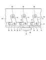
- FIG. 6 is a schematic view showing a bracket mounting portion of the ring.
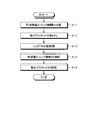
- FIG. 7 is a flowchart showing a maintenance method for the variable stationary blade device.
- FIG. 8 is a schematic diagram illustrating the overall configuration of the gas turbine.
- FIG. 9 is a main part schematic diagram showing the variable stationary blade device of the second embodiment.
- FIG. 10 is a schematic diagram illustrating a maintenance method for the variable stationary blade device.
- FIG. 11 is a main part schematic diagram showing the variable stationary blade device of the third embodiment.
- FIG. 12
- variable stator blade device maintenance method and a variable stator blade device according to the present invention will be described below in detail with reference to the accompanying drawings.
- this invention is not limited by this embodiment, Moreover, when there are two or more embodiment, what comprises combining each embodiment is also included.
- FIG. 8 is a schematic diagram illustrating the overall configuration of the gas turbine according to the first embodiment.
- the gas turbine 10 includes a compressor 11, a combustor 12, and a turbine 13.
- the compressor 11 and the turbine 13 are disposed along the direction of the axis O on the outside of the rotating shaft 32, and a plurality of combustors 12 are disposed between the compressor 11 and the turbine 13. ing.
- the gas turbine 10 is connected to a generator (electric motor) (not shown) on the same axis and can generate power.
- the compressor 11 has an air intake 20 for taking in air, an inlet guide vane (IGV: Inlet Guide Vane) 22 as a variable vane is disposed in a compressor casing 21, and a plurality of vanes 23. And a plurality of moving blades 24 are alternately arranged in the air flow direction (the direction of the axis O of the rotor 32 to be described later), and a bleed chamber 25 is provided outside thereof.
- the compressor 11 generates high-temperature and high-pressure compressed air by compressing the air taken in from the air intake port 20 and is supplied to the passenger compartment 14.
- the compressor 11 is started by an electric motor connected on the same axis.
- the combustor 12 is supplied with high-temperature and high-pressure compressed air and fuel that have been compressed by the compressor 11 and stored in the vehicle compartment 14 and burns to generate combustion gas.
- a plurality of stationary blades 27 and a plurality of moving blades 28 are alternately arranged in a turbine casing 26 in the flow direction of combustion gas (the direction of the axis O of the rotor 32).
- the turbine casing 26 is provided with an exhaust chamber 30 on the downstream side via an exhaust casing 29, and the exhaust chamber 30 has an exhaust diffuser 31 connected to the turbine 13.
- the turbine 13 is driven by the combustion gas from the combustor 12 and drives a generator connected on the same axis.
- a rotor (rotary shaft) 32 is disposed along the direction of the axis O so as to penetrate the central portion of the exhaust chamber 30.
- the end of the rotor 32 on the compressor 11 side is rotatably supported by the bearing portion 33, and the end of the exhaust chamber 30 side is rotatably supported by the bearing portion 34.
- the rotor 32 is fixed by a compressor 11 in which a plurality of disks on which the moving blades 24 are mounted are stacked.
- a plurality of disks on which the moving blades 28 are mounted are stacked and fixed in the turbine 13, and a drive shaft of the generator is connected to an end portion on the exhaust chamber 30 side.
- the compressor casing 21 of the compressor 11 is supported by the legs 35
- the turbine casing 26 of the turbine 13 is supported by the legs 36
- the exhaust chamber 30 is supported by the legs 37. Yes.
- the air taken in from the air intake 20 by the compressor 11 passes through the inlet guide vane 22, the plurality of stationary vanes 23, and the moving vanes 24 and is compressed to become high-temperature and high-pressure compressed air. .
- a predetermined fuel is supplied to the compressed air in the combustor 12 and burned.
- the high-temperature and high-pressure combustion gas generated in the combustor 12 drives and rotates the rotor 32 by passing through the plurality of stationary blades 27 and the moving blades 28 in the turbine 13, and is connected to the rotor 32. Drive the generator. And the combustion gas which drove the turbine 13 is discharge
- FIG. 1 is a front view showing the variable stator blade device of the first embodiment
- FIG. 2 is a cross-sectional view of the main part of the variable stator blade device showing the II-II section of FIG. 1, and FIG. FIG.
- variable stationary blade device 50 includes a plurality of inlet guide vanes (variable stationary blades) 22, a ring 51, a driving force transmission mechanism 52, and a driving device 53. .
- the casing 61 has a double cylindrical shape, and an annular flow path 64 is provided between the outer cylinder 62 and the inner cylinder 63.
- the inlet guide vane 22 includes a shaft portion 65 and a blade portion 66.
- the plurality of inlet guide vanes 22 are annularly arranged in the casing 61 at a predetermined interval. That is, the inlet guide vane 22 has a shaft portion 65 that is rotatably supported through the outer tube 62, and the blade portion 66 is positioned in a flow path 64 provided between the outer tube 62 and the inner tube 63. Yes.
- the ring 51 has a ring shape in which an upper ring 67 and a lower ring 68 having a semi-ring shape are integrally fixed, and is arranged outside the outer cylinder 62 in the casing 61.
- the upper ring 67 and the lower ring 68 are in close contact with flange portions 67a and 68a, and are fixed by fastening bolts (not shown).
- a plurality of support members 69 are fixed to the outer peripheral portion of the outer cylinder 62 at predetermined intervals in the circumferential direction, and guide rollers (guides) 70 are respectively supported by the support members 69.
- Each guide roller 70 is rotatably supported by each support member 69 by a support shaft 71 along the axial direction of the casing 61.
- the ring 51 is rotatably supported on the outer peripheral portion of the casing 61 by the outer peripheral support surface 51 a being supported by the plurality of guide rollers 70.
- the driving force transmission mechanism 52 is a link mechanism, and the angle of the plurality of inlet guide vanes 22 can be changed by transmitting the rotational force of the ring 51 to the plurality of inlet guide vanes 22.
- the driving force transmission mechanism 52 is configured such that each end of the first link 72 and the second link 73 is rotatably connected by a connecting shaft 74.
- the other end of the first link 72 is rotatably supported on the ring 51 by the connecting shaft 75, and the shaft 65 of the inlet guide vane 22 is integrally fixed to the other end of the second link 73. Yes.
- the rotational force is transmitted to each inlet guide vane 22 via the driving force transmission mechanism (link mechanism) 52, and each inlet guide vane 22 rotates in one direction.
- the flow path 64 can be closed.
- the driving force is transmitted to each inlet guide vane 22 via the driving force transmission mechanism (link mechanism) 52, and each inlet guide vane 22 rotates in the other direction.
- the flow path 64 can be opened.
- the drive device 53 is an actuator and has a drive rod (drive unit) 76 that can reciprocate in the axial direction.
- the drive rod 76 has a swinging link 77 that is rotatable.
- the driving device 53 is fixed to a support bracket 78, and the support bracket 78 is fixed to the casing 61 by a plurality of fastening bolts 79.
- the mounting bracket 80 is fixed to the lower part of the ring 51. In the driving device 53, the distal end portion of the driving rod 76 is connected to the mounting bracket 80.
- variable vane device 50 a ring 51 for rotating the plurality of inlet guide vanes 22 is rotatably supported by a plurality of guide rollers 70. Then, by rotating the ring 51 by the driving device 53, each variable stationary blade 22 is rotated via the driving force transmission mechanism 52. In this case, since the ring 51 is rotated by a predetermined angle by the driving device 53, each guide roller 70 is in contact and supported only in a predetermined same region in the ring 51. For this reason, the ring 51 is worn only in a region where the guide roller 70 is in contact with the ring 51, and thinning occurs.
- the wear area in the ring 51 is not used by shifting the positional relationship between the ring 51 and the plurality of guide rollers 70 in the circumferential direction.
- FIG. 4 is a front view showing the mounting state of the ring before repair
- FIG. 5 is a front view showing the mounting state of the ring after repair
- FIG. 6 is a schematic diagram showing the bracket mounting portion of the ring
- FIG. It is a flowchart showing the maintenance method of a variable stationary blade apparatus.
- the variable stator blade device maintenance method of the first embodiment includes a releasing step of releasing the connection between the plurality of variable stator blades 22 and the ring 51, a turning step of rotating the ring 51 by a predetermined angle, and a plurality of variable.
- variable stator blade device maintenance method of the first embodiment releases the connection between the plurality of variable stator blades 22 and the ring 51 and releases the connection between the ring 51 and the drive device 53 in the release step.
- the plurality of variable stationary blades 22 and the ring 51 are connected at a position different from that before the releasing process, and the ring 51 and the driving device 53 are connected at a different position from before the releasing process.
- the mounting bracket 80 is fixed to the ring 51, and in the driving device 53, the driving rod 76 is connected to the mounting bracket 80.
- the mounting bracket 80 is released from the ring 51. Fix in a different position from before the process.
- the driving force transmission mechanism (link mechanism) 52 is disassembled in the release step, and the driving force transmission mechanism 52 is assembled in the connection step.
- the ring 51 In the rotation process, it is desirable to rotate the ring 51 by an integral multiple of the angle between the arrangement intervals of the plurality of variable stationary blades 22. However, in this rotation process, the ring may be rotated by 180 degrees.
- the ring 51 is provided at a position where a plurality (two in this embodiment) of connecting portions 81 and 82 for mounting the mounting bracket 80 are shifted in the circumferential direction.
- the first connecting portion 81 is five mounting holes 81 a, 81 b, 81 c, 81 d, 81 e formed at predetermined intervals in the circumferential direction of the ring 51, and the second connecting portion 82 is predetermined in the circumferential direction of the ring 51.
- the connecting portions 81 and 82 are provided apart by an integral multiple (in this embodiment, twice) of the mounting pitch (distance) of the variable stator blades 22 in the ring 51.
- the mounting bracket 80 overlaps the first connecting portion 81 (mounting holes 81 a, 81 b, 81 c, 81 d, 81 e) at the lower end portion of the ring 51, and is fastened by a plurality of fastening bolts 85.
- the alternate long and short dash line A is the mounting position of the variable stationary blade 22, and the second connecting portion 82 (mounting holes 82a, 82b, 82c, 82d, 82e) is connected to the first connecting portion 81 (mounting holes 81a, 81b, 81c, 81d, and 81e) are shifted by two pitches in the clockwise direction in the ring 51.
- the mounting bracket 80 is moved to the second connecting portion 82 (mounting hole 82a) as shown in FIG. , 82b, 82c, 82d, 82e) and can be fastened by a plurality of fastening bolts 85a, 85b, 85c, 85d, 85e.
- step S ⁇ b> 11 each variable stationary blade 22 and the ring 51 are separated by disassembling the driving force transmission mechanism (link mechanism) 52.
- the connection between the shaft portion 65 of the variable stator blade 22, the first link 72, the second link 73, and the connecting shafts 74 and 75 is released. Note that the connection between the shaft portion 65 of the variable stationary blade 22 and the second link 73 may be simply released.
- step S12 the mounting bracket 80 is removed in step S12.
- the fastening bolt 85 is loosened to release the connection between the ring 51 and the mounting bracket 80, and the connection between the mounting bracket 80 and the drive rod 76 of the drive device 53 is released.
- step S13 the ring 51 is rotated and position adjustment is performed. That is, since the connection between each variable stator blade 22 and the ring 51 is released and the connection between the ring 51 and the mounting bracket 80 is released, the ring 51 can be freely rotated. Therefore, the ring 51 is rotated counterclockwise by twice (2 pitches) the mounting pitch of the variable stationary blade 22.
- step S14 the variable stator blades 22 and the ring 51 are connected by assembling the driving force transmission mechanism 52. At this time, it is necessary for each variable stationary blade 22 to assemble the driving force transmission mechanism 52 without changing its angle before disassembly of the driving force transmission mechanism 52 and during assembly.
- step S ⁇ b> 15 the mounting bracket 80 is fixed to the second connecting portion 82. In this case, the mounting bracket 80 is overlapped with the second connecting portion 82 in the ring 51 and fastened by a plurality of fastening bolts 85, and the mounting bracket 80 and the drive rod 76 of the drive device 53 are connected.
- the first connecting portion 81 for attaching the mounting bracket 80 to the ring 51 and the first connecting portion 81 are attached at positions shifted in the circumferential direction.
- the ring 51 having the mounting bracket 80 attached to the first connecting portion 81 is prepared, and the connection between the plurality of variable stationary blades 22 and the ring 51, and the ring 51 are prepared.
- the mounting bracket 80 at the first connecting portion 81 are released, the ring 51 is rotated by a predetermined angle, and then the plurality of variable vanes 22 and the ring 51 are connected at a position different from that before the releasing step.
- the ring 51 and the mounting bracket 80 are connected at the second connecting portion 82. Therefore, the position where the ring 51 is supported by the plurality of guide rollers 70 is changed, and the plurality of guide rollers 70 can properly support the ring 51 in a region where the ring 51 is not worn. The performance can be maintained by preventing the malfunction.
- the position of the ring 51 by the plurality of guide rollers 70 is changed without changing the connection relationship between the plurality of variable stator blades 22 and the ring 51 and the connection relationship between the ring 51 and the driving device 53. High operating accuracy in the blade 22 can be maintained. Furthermore, since the connecting position of the driving device 53 and the ring 51 is changed by changing the mounting position of the mounting bracket 80 on the ring 51, the supporting position of the ring 51 by the plurality of guide rollers 70 can be easily set with a simple configuration. Can be changed.
- the plurality of variable stator blades 22 and the ring 51 are connected via the driving force transmission mechanism 52, and in the releasing step, the driving force transmission mechanism 52 is disassembled, In the connecting step, the driving force transmission mechanism 52 is assembled. Therefore, the relationship between the plurality of variable stationary blades 22 and the ring 51 is changed by disassembling and assembling the driving force transmission mechanism 52, and workability can be improved.
- the ring 51 is arranged at a plurality of variable stator blades 22, that is, the integer of the mounting distance between the variable stator blades 22. Rotate by twice. Therefore, since the relationship between the plurality of variable stator blades 22 and the ring 51 is changed by shifting the mounting distance between the variable stator blades 22, the plurality of guide rollers 70 and the ring can be changed without changing the operating region of the variable stator blades.
- the support position with 51 can be changed.
- the ring 51 may be rotated by 180 degrees in the rotation process. That is, since the weight of the ring 51 is supported by the guide roller 70 disposed at the lower position, the support region of the lower portion of the ring 51 by the guide roller 70 is likely to be worn. Therefore, the support position of the plurality of guide rollers 70 and the ring 51 can be changed by rotating the ring 51 by 180 ° C. and reversing it up and down.
- variable stator blade device In the variable stator blade device of the first embodiment, the variable stator blade device is rotatably supported by a plurality of variable stator blades 22 arranged in an annular shape surrounding the flow path 64 and a plurality of guide rollers 70 provided on the outer peripheral portion. And a ring 51 provided with a plurality of connecting portions 81 and 82 at positions displaced in the circumferential direction and connected to the plurality of variable stator blades 22 and the plurality of variable stator blades 22 and the ring 51.
- a driving force transmission mechanism 52 and a driving device 53 in which the driving rod 76 is connected by one of a plurality of connecting portions 81 and 82 in the ring 51 are provided.
- the ring 51 is rotated by a predetermined opening and the drive rod 76 is rotated.
- the connecting position from the first connecting portion 81 to the second connecting portion 82, the position where the ring 51 is supported by the plurality of guide rollers 70 is changed.
- the ring 51 can be supported at a place where the ring 51 is not worn, and the performance can be maintained by preventing the variable stator blade 22 from malfunctioning.
- the ring 51 is provided with two connecting portions 81 and 82 that are shifted in the circumferential direction.
- the number of connecting portions is not limited to two, and three or more connecting portions may be provided. is there.
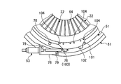
- FIG. 9 is a main part schematic diagram showing the variable stationary blade device of the second embodiment
- FIG. 10 is a schematic diagram showing a maintenance method of the variable stationary blade device.
- symbol is attached
- the maintenance method for the variable stationary blade device of the second embodiment includes a releasing step for releasing the connection between the plurality of variable stationary blades 22 and the ring 51, and rotating the ring 51 by a predetermined angle.
- the release step the connection between the plurality of variable stator blades 22 and the ring 51 is released, and the connection between the ring 51 and the drive device 53 is released.
- the moving step the ring 51 is rotated by a predetermined angle, and in the connecting step, the plurality of variable vanes 22 and the ring 51 are connected at positions different from those before the releasing step, and the ring 51 and the driving device 53 are connected. Are connected at different positions.
- the mounting bracket 101 is fixed to the ring 51, and the driving device 53 connects the driving rod 76 to the mounting bracket 101 and connects the driving rod 76 to the mounting bracket 101 at a different position. .
- the mounting bracket 101 is fixed by a plurality of fastening bolts 104, and the mounting bracket 101 includes a plurality of (in this embodiment, for connecting the driving rod 76 of the driving device 53).
- Two) connecting portions 102 and 103 are provided at positions shifted in the circumferential direction.
- the first connecting portion 102 is provided at one end of the mounting bracket 101 in the longitudinal direction (circumferential direction of the ring 51), and the second connecting portion 103 is the other end of the mounting bracket 101 in the longitudinal direction (circumferential direction of the ring 51).
- the connecting portions 102 and 103 are provided apart by an integral multiple (in this embodiment, twice) of the mounting pitch (distance) of the variable stator blades 22 in the ring 51.
- each variable stationary blade 22 and the ring 51 are separated by disassembling the driving force transmission mechanism (link mechanism) 52.
- the connection between the drive rod 76 of the drive device 53 and the first connection portion 102 of the mounting bracket 101 is released.
- the ring 51 is rotated counterclockwise by twice (2 pitches) the mounting pitch of the variable stator blades 22.
- each variable stator blade 22 and the ring 51 are connected by assembling the driving force transmission mechanism 52. Then, the driving rod 76 of the driving device 53 is connected to the second connecting portion 103 of the mounting bracket 101.
- the bracket 101 is fixed, and the drive rod 76 of the drive device 53 can be connected to any one of the connecting portions 102 and 103.
- the ring 51 having the mounting bracket 101 attached to the first connecting portion 102 is prepared, and the connection between the plurality of variable stationary blades 22 and the ring 51 is released.
- the plurality of variable stationary blades 22 and the ring 51 are released in the releasing step.
- the drive rod 76 of the drive device 53 is connected to the second connection portion 103 of the mounting bracket 101 while being connected at a position different from the previous position.
- the position where the ring 51 is supported by the plurality of guide rollers 70 is changed, and the plurality of guide rollers 70 can properly support the ring 51 in an area where the ring 51 is not worn.
- the performance can be maintained by preventing malfunction of the variable stationary blade 22.
- the connecting position of the drive device 53 and the ring 51 is changed by changing the mounting position of the drive rod 76 in the bracket 101, it is not necessary to remove the mounting bracket 101, and a plurality of guides can be easily made with a simple configuration. The position of the ring 51 by the roller 70 can be changed.
- FIG. 11 is a main part schematic diagram showing the variable stationary blade device of the third embodiment.
- symbol is attached
- the maintenance method for the variable stator blade device of the third embodiment includes a releasing step for releasing the connection between the plurality of variable stator blades 22 and the ring 51, and a rotation for rotating the ring 51 by a predetermined angle.
- the driving device 111 has a stroke larger than the stroke of rotating the variable stationary blade 22.
- the drive device 111 is an actuator and has a drive rod (drive unit) 112 that can reciprocate in the axial direction.
- the drive rod 112 has a swing link 113 that can freely rotate.
- the driving device 111 is fixed to the support bracket 114, and the support bracket 114 is fixed to the casing 61 by a plurality of fastening bolts 115.
- the distal end portion of the driving rod 112 is connected to the mounting bracket 80.
- each variable stationary blade 22 and the ring 51 are separated by disassembling the driving force transmission mechanism (link mechanism) 52.
- the drive device 111 is driven to extend the drive rod 76, and the ring 51 is rotated counterclockwise by the mounting pitch of the variable stationary blade 22.
- each variable stator blade 22 and the ring 51 are connected by assembling the driving force transmission mechanism 52.
- the stroke S1 of the variable stationary blade 22 is changed to the stroke S2.
- the stroke region between the fully open and the fully closed state where the drive device 111 rotates the variable stationary blade 22 is changed in the circumferential direction of the ring 51. . Accordingly, when the ring 51 is worn at the support position by the guide roller 70, the connection between the plurality of variable stator blades 22 and the ring 51 is released, the ring 51 is rotated by a predetermined angle, and then the plurality of variable stator blades 22 and the ring 51 are rotated. Are connected at a position different from that before the releasing step.
- the position where the ring 51 is supported by the plurality of guide rollers 70 is changed, and the plurality of guide rollers 70 can properly support the ring 51 in an area where the ring 51 is not worn.
- the performance can be maintained by preventing malfunction of the variable stationary blade 22.
- the stroke area of the driving device 111 in the circumferential direction of the ring 51 the support position of the ring 51 by the guide roller 70 is changed, so that it is not necessary to remove the mounting bracket 101, and it is easy with a simple configuration.
- the position of the ring 51 by the plurality of guide rollers 70 can be changed.
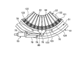
- FIG. 12 is a main part schematic diagram showing the variable stationary blade device of the fourth embodiment.
- symbol is attached
- the maintenance method for the variable stator blade device of the fourth embodiment releases the connection between the plurality of variable stator blades 22 and the ring 51 and the connection between the ring 51 and the drive device 53.
- the step, the turning step of turning the ring 51 by a predetermined angle, the plurality of variable stationary blades 22 and the ring 51 are connected at different positions, and the ring 51 and the driving device 53 are different from those before the releasing step.
- the driving force transmission mechanism 121 is a gear mechanism, and the angle of the plurality of inlet guide vanes 22 can be changed by transmitting the rotational force of the ring 51 to the plurality of inlet guide vanes 22. That is, the drive gear 123 is fixed to the shaft portion 122 of the inlet guide vane 22, while the rack 51 is provided on the ring 51, and the drive gear 123 of each inlet guide vane 22 meshes with the rack 124 of the ring 51. ing.
- each inlet guide vane 22 rotates to open and close the flow path 64. be able to.
- each variable stationary blade 22 and the ring 51 are separated by disassembling the driving force transmission mechanism 121.
- the connection between the drive rod 76 of the drive device 53 and the mounting bracket 80 is released.
- the ring 51 is rotated counterclockwise by twice (2 pitches) the mounting pitch of the variable stator blades 22.
- each variable stator blade 22 and the ring 51 are connected by assembling the driving force transmission mechanism 121. Then, the drive rod 76 of the drive device 53 is connected to the mounting bracket 80.
- the releasing step for releasing the connection between the plurality of variable stationary blades 22 and the ring 51 and the rotation for rotating the ring 51 by a predetermined angle As described above, in the maintenance method for the variable stationary blade device according to the fourth embodiment, the releasing step for releasing the connection between the plurality of variable stationary blades 22 and the ring 51 and the rotation for rotating the ring 51 by a predetermined angle.
- release process are provided.
- the position where the ring 51 is supported by the plurality of guide rollers 70 is changed, and the plurality of guide rollers 70 can properly support the ring 51 in a region where the ring 51 is not worn.
- the performance can be maintained by preventing malfunction of the variable stationary blade 22.
- the maintenance method for the variable stationary blade device of the present invention is not limited to the above-described embodiments.
- the connection between the plurality of variable stator blades and the ring is released, the connection between the casing and the driving device is released, the ring is rotated by a predetermined opening, and then the plurality of variable stator blades and the ring are moved to different positions.
- the casing and the driving device may be connected at different positions.
- a position adjusting mechanism is provided by engaging the pin and the elongated hole at any one position between the ring and the mounting bracket, between the mounting bracket and the driving unit, and between the driving device and the casing. You may make it fix so that it cannot move with a fastening bolt after adjustment.
- the position of the plurality of guide rollers may be freely adjustable with respect to the circumferential direction of the ring 51 in the casing, and the support position with respect to the ring may be changed by shifting the positions of the plurality of guide rollers.
- the guide roller 70 is used as the guide of the present invention.
- the guide roller 70 is not limited to a roller that rolls, and a sliding member that slides may be used.
Landscapes
- Engineering & Computer Science (AREA)
- Mechanical Engineering (AREA)
- General Engineering & Computer Science (AREA)
- Chemical & Material Sciences (AREA)
- Combustion & Propulsion (AREA)
- Physics & Mathematics (AREA)
- Geometry (AREA)
- Structures Of Non-Positive Displacement Pumps (AREA)
- Manufacture Of Motors, Generators (AREA)
Abstract
Description
図8は、第1本実施形態のガスタービンの全体構成を表す概略図である。
図9は、第2実施形態の可変静翼装置を表す要部概略図、図10は、可変静翼装置のメンテナンス方法を表す概略図である。なお、上述した実施形態と同様の機能を有する部材には、同一の符号を付して詳細な説明は省略する。
図11は、第3実施形態の可変静翼装置を表す要部概略図である。なお、上述した実施形態と同様の機能を有する部材には、同一の符号を付して詳細な説明は省略する。
図12は、第4実施形態の可変静翼装置を表す要部概略図である。なお、上述した実施形態と同様の機能を有する部材には、同一の符号を付して詳細な説明は省略する。
11 圧縮機
12 燃焼器
13 タービン
14 車室
21 圧縮機車室
22 入口案内翼(可変静翼)
23 静翼
24 動翼
32 ロータ(回転軸)
50 可変静翼装置
51 リング
52 駆動力伝達機構(リンク機構)
53,111 駆動装置
61 ケーシング
64 流路
70 ガイドローラ(ガイド)
72 第1リンク
73 第2リンク
76,112 駆動ロッド(駆動部)
80,101 取付ブラケット
81,102 第1連結部
82,103 第2連結部
85 締結ボルト
121 駆動力伝達機構
123 駆動歯車
124 ラック
Claims (5)
- 回転機械に設けられ、流体流路を囲んで環状配置される複数の可変静翼と、
前記回転機械の外周部に設けられた複数のガイドにより前記回転機械の中心軸に対して回転可能に支持されると共に、前記複数の可変静翼と連結されたリングと、
前記リングに固定された取付ブラケットと、
前記取付ブラケットに連結された駆動装置と、
を有し、
前記駆動装置が前記リングを回動することで、前記複数の可変静翼を揺動可能な可変静翼装置において、
前記リングであって、前記取付ブラケットを取付ける第1連結部と、第1連結部とは周方向にずれた位置で前記取付ブラケットを取付ける第2連結部と、を有し、前記第1連結部に前記取付ブラケットが取付けられた前記リングを準備する準備工程と、
前記複数の可変静翼と前記リングとの連結と、前記リングと前記取付ブラケットとの前記第1連結部における連結と、を解除する解除工程と、
前記リングを所定角度だけ回動する回動工程と、
前記複数の可変静翼と前記リングとを前記解除工程の前とは異なる位置で連結し、且つ、前記リングと前記ブラケットとを前記第2連結部において連結する連結工程と、
を有することを特徴とする可変静翼装置のメンテナンス方法。 - 前記複数の可変静翼と前記リングとがリンク機構を介して連結され、前記解除工程では、前記リンク機構を解体し、前記連結工程では、前記リンク機構を組み立てることを特徴とする請求項1に記載の可変静翼装置のメンテナンス方法。
- 前記回動工程は、前記リングを前記複数の可変静翼におけるそれぞれの配置間隔の角度の整数倍だけ回動することを特徴とする請求項1または請求項2に記載の可変静翼装置のメンテナンス方法。
- 前記回動工程にて、前記リングを180度だけ回動することを特徴とする請求項1または請求項2に記載の可変静翼装置のメンテナンス方法。
- 回転機械の可変静翼装置であって、
流体流路を囲んで環状配置される複数の可変静翼と、
前記回転機械の外周部に設けられた複数のガイドにより前記回転機械の中心軸に対して回転可能に支持され、前記複数の可変静翼と連結されると共に、周方向にずれた位置に複数の連結部が設けられたリングと、
前記複数の連結部のうちの一つに連結されて前記リングを回転させる駆動装置と、
を有することを特徴とする可変静翼装置。
Priority Applications (5)
| Application Number | Priority Date | Filing Date | Title |
|---|---|---|---|
| KR1020167034172A KR101850237B1 (ko) | 2014-07-10 | 2015-06-18 | 가변 정익 장치의 메인터넌스 방법 및 가변 정익 장치 |
| CN201580029827.8A CN106460871B (zh) | 2014-07-10 | 2015-06-18 | 可变静叶装置的维护方法以及可变静叶装置 |
| DE112015003201.0T DE112015003201B4 (de) | 2014-07-10 | 2015-06-18 | Wartungsverfahren für variable leitflügelvorrichtung und variable leitflügelvorrichtung |
| JP2016532847A JP6298529B2 (ja) | 2014-07-10 | 2015-06-18 | 可変静翼装置のメンテナンス方法及び可変静翼装置 |
| US15/316,999 US10858993B2 (en) | 2014-07-10 | 2015-06-18 | Variable vane device maintenance method and variable vane device |
Applications Claiming Priority (2)
| Application Number | Priority Date | Filing Date | Title |
|---|---|---|---|
| US201462023078P | 2014-07-10 | 2014-07-10 | |
| US62/023,078 | 2014-07-10 |
Publications (1)
| Publication Number | Publication Date |
|---|---|
| WO2016006411A1 true WO2016006411A1 (ja) | 2016-01-14 |
Family
ID=55064051
Family Applications (1)
| Application Number | Title | Priority Date | Filing Date |
|---|---|---|---|
| PCT/JP2015/067631 Ceased WO2016006411A1 (ja) | 2014-07-10 | 2015-06-18 | 可変静翼装置のメンテナンス方法及び可変静翼装置 |
Country Status (7)
| Country | Link |
|---|---|
| US (1) | US10858993B2 (ja) |
| JP (1) | JP6298529B2 (ja) |
| KR (1) | KR101850237B1 (ja) |
| CN (1) | CN106460871B (ja) |
| DE (1) | DE112015003201B4 (ja) |
| TW (1) | TWI582313B (ja) |
| WO (1) | WO2016006411A1 (ja) |
Cited By (2)
| Publication number | Priority date | Publication date | Assignee | Title |
|---|---|---|---|---|
| CN114776634A (zh) * | 2022-05-12 | 2022-07-22 | 中国空气动力研究与发展中心空天技术研究所 | 一种发动机进口导叶角度调节机构 |
| CN116351518A (zh) * | 2019-06-14 | 2023-06-30 | 古河机械金属株式会社 | 粉碎装置、无机材料的制造方法及粉碎方法 |
Families Citing this family (4)
| Publication number | Priority date | Publication date | Assignee | Title |
|---|---|---|---|---|
| US10519797B2 (en) * | 2016-06-27 | 2019-12-31 | General Electric Company | Turbine engine and stator vane pitch adjustment system therefor |
| DE102018101527A1 (de) * | 2018-01-24 | 2019-07-25 | Man Energy Solutions Se | Axialströmungsmaschine |
| KR20220011988A (ko) | 2020-07-22 | 2022-02-03 | 한국전력공사 | 가스 터빈 압축기 igv 손상방지장치 |
| DE102023110935A1 (de) * | 2023-04-27 | 2024-10-31 | MTU Aero Engines AG | Elastisch zentrierte Synchronisierungseinrichtung |
Citations (6)
| Publication number | Priority date | Publication date | Assignee | Title |
|---|---|---|---|---|
| JPS59231106A (ja) * | 1983-05-31 | 1984-12-25 | ズルツア−−エツシヤ−・ウイス・アクチエンゲゼルシヤフト | 軸流タ−ビン装置のステ−タベ−ン制御機構 |
| JP2004124849A (ja) * | 2002-10-03 | 2004-04-22 | Mitsubishi Heavy Ind Ltd | 可変静翼駆動装置及び回転機械 |
| JP2006194243A (ja) * | 2004-12-16 | 2006-07-27 | Snecma | 電動モータ手段によって移動される回転アクチュエータリングによって作動するステータ翼ステージ |
| JP2009097510A (ja) * | 2007-10-12 | 2009-05-07 | Snecma | ターボ機械のステータ翼用ピッチ制御リングの改善 |
| US20100189549A1 (en) * | 2009-01-26 | 2010-07-29 | Rolls-Royce Plc | Variable vane assembly |
| US20120042507A1 (en) * | 2010-08-19 | 2012-02-23 | Lozier Thomas S | Variable vane calibration method and kit |
Family Cites Families (14)
| Publication number | Priority date | Publication date | Assignee | Title |
|---|---|---|---|---|
| GB191516592A (en) | 1914-12-18 | 1916-05-11 | Anilin Fabrikation Ag | Manufacture of Mordant Dyestuffs. |
| US3227176A (en) * | 1962-12-31 | 1966-01-04 | Gen Electric | Windmill control system for multiengined aircraft |
| JPS4716807U (ja) | 1971-03-29 | 1972-10-27 | ||
| DE3711224A1 (de) * | 1987-04-03 | 1988-10-13 | Gutehoffnungshuette Man | Verstelleinrichtung fuer die leitschaufeln einer axialstroemungsmaschine |
| JPH0637596U (ja) | 1992-10-21 | 1994-05-20 | 三菱重工業株式会社 | 静翼操作環 |
| GB0416888D0 (en) * | 2004-07-29 | 2004-09-01 | Rolls Royce Plc | Controlling a plurality of devices |
| JP2008101821A (ja) * | 2006-10-18 | 2008-05-01 | Mitsubishi Heavy Ind Ltd | ボルトヒータ及びボルトヒーティングシステム |
| JP5055208B2 (ja) | 2008-06-20 | 2012-10-24 | 三菱重工業株式会社 | 軸流圧縮機の可変静翼駆動方法及び装置 |
| US8668443B2 (en) | 2010-01-08 | 2014-03-11 | Honeywell International Inc. | Variable-vane assembly having unison ring guided radially by rollers and fixed members, and restrained axially by one or more fixed axial stops |
| EP2354560A1 (en) * | 2010-01-28 | 2011-08-10 | Siemens Aktiengesellschaft | Device for adjusting variable guide vanes |
| JP5716918B2 (ja) * | 2011-11-02 | 2015-05-13 | 三菱日立パワーシステムズ株式会社 | 軸流流体機械、及びその可変静翼駆動装置 |
| DE102011088820A1 (de) | 2011-12-16 | 2013-06-20 | Siemens Aktiengesellschaft | Strömungsmaschine und Verfahren zum Betreiben einer solchen |
| US9284851B2 (en) * | 2012-02-21 | 2016-03-15 | Mitsubishi Heavy Industries, Ltd. | Axial-flow fluid machine, and variable vane drive device thereof |
| EP3019715B1 (en) * | 2013-07-12 | 2020-01-15 | United Technologies Corporation | Method to repair variable vanes |
-
2015
- 2015-06-18 DE DE112015003201.0T patent/DE112015003201B4/de active Active
- 2015-06-18 JP JP2016532847A patent/JP6298529B2/ja active Active
- 2015-06-18 KR KR1020167034172A patent/KR101850237B1/ko active Active
- 2015-06-18 WO PCT/JP2015/067631 patent/WO2016006411A1/ja not_active Ceased
- 2015-06-18 US US15/316,999 patent/US10858993B2/en active Active
- 2015-06-18 CN CN201580029827.8A patent/CN106460871B/zh active Active
- 2015-07-02 TW TW104121495A patent/TWI582313B/zh active
Patent Citations (6)
| Publication number | Priority date | Publication date | Assignee | Title |
|---|---|---|---|---|
| JPS59231106A (ja) * | 1983-05-31 | 1984-12-25 | ズルツア−−エツシヤ−・ウイス・アクチエンゲゼルシヤフト | 軸流タ−ビン装置のステ−タベ−ン制御機構 |
| JP2004124849A (ja) * | 2002-10-03 | 2004-04-22 | Mitsubishi Heavy Ind Ltd | 可変静翼駆動装置及び回転機械 |
| JP2006194243A (ja) * | 2004-12-16 | 2006-07-27 | Snecma | 電動モータ手段によって移動される回転アクチュエータリングによって作動するステータ翼ステージ |
| JP2009097510A (ja) * | 2007-10-12 | 2009-05-07 | Snecma | ターボ機械のステータ翼用ピッチ制御リングの改善 |
| US20100189549A1 (en) * | 2009-01-26 | 2010-07-29 | Rolls-Royce Plc | Variable vane assembly |
| US20120042507A1 (en) * | 2010-08-19 | 2012-02-23 | Lozier Thomas S | Variable vane calibration method and kit |
Cited By (3)
| Publication number | Priority date | Publication date | Assignee | Title |
|---|---|---|---|---|
| CN116351518A (zh) * | 2019-06-14 | 2023-06-30 | 古河机械金属株式会社 | 粉碎装置、无机材料的制造方法及粉碎方法 |
| CN114776634A (zh) * | 2022-05-12 | 2022-07-22 | 中国空气动力研究与发展中心空天技术研究所 | 一种发动机进口导叶角度调节机构 |
| CN114776634B (zh) * | 2022-05-12 | 2023-11-03 | 中国空气动力研究与发展中心空天技术研究所 | 一种发动机进口导叶角度调节机构 |
Also Published As
| Publication number | Publication date |
|---|---|
| CN106460871A (zh) | 2017-02-22 |
| JPWO2016006411A1 (ja) | 2017-04-27 |
| DE112015003201T5 (de) | 2017-03-23 |
| JP6298529B2 (ja) | 2018-03-20 |
| TW201608136A (zh) | 2016-03-01 |
| US20170114719A1 (en) | 2017-04-27 |
| TWI582313B (zh) | 2017-05-11 |
| CN106460871B (zh) | 2019-02-12 |
| KR20170005453A (ko) | 2017-01-13 |
| DE112015003201B4 (de) | 2025-03-13 |
| US10858993B2 (en) | 2020-12-08 |
| KR101850237B1 (ko) | 2018-04-18 |
Similar Documents
| Publication | Publication Date | Title |
|---|---|---|
| JP6298529B2 (ja) | 可変静翼装置のメンテナンス方法及び可変静翼装置 | |
| US9797265B2 (en) | Stator vane adjusting device of a gas turbine | |
| JP6412073B2 (ja) | ガスタービンエンジンのための多方向ギアボックス偏位制限器 | |
| US8376693B2 (en) | Variable vane assembly | |
| JP5564106B2 (ja) | ターボ機械用の可変ピッチブレードを有するアンダクテッドプロペラ | |
| US20070020092A1 (en) | Gear train variable vane synchronizing mechanism for inner diameter vane shroud | |
| US20120308364A1 (en) | Drive device for pivoting adjustable blades of a turbomachine | |
| JP5055208B2 (ja) | 軸流圧縮機の可変静翼駆動方法及び装置 | |
| US9422825B2 (en) | Gas turbine engine synchronization ring | |
| JP2007024048A (ja) | 可変ベーンシュラウド、ステータベーン部、可変ベーンアッセンブリおよび可変ベーン | |
| JP2017096268A (ja) | 可変ピッチファンアクチュエータ | |
| JP2017008938A (ja) | タービンエンジン用のトラニオン保持 | |
| KR20110045444A (ko) | 가변 지오메트리 터보차져의 노즐어셈블리 | |
| US10436151B2 (en) | Modular fan for a gas turbine engine | |
| WO2014133724A1 (en) | Rotary actuator for variable vane adjustment system | |
| US10495107B2 (en) | Guide vane assembly with compensation device | |
| CA2894032C (en) | Single bolting flange arrangement for variable guide vane connection | |
| CN112443364B (zh) | 用于同心可变定子静叶的促动组件 | |
| JP2010159750A (ja) | 位置可変型案内羽根作動システムおよび方法 | |
| US20160123339A1 (en) | Radial fastening of tubular synchronizing rings | |
| US20140127003A1 (en) | Stator vane adjusting device of a gas turbine | |
| JP2014047783A (ja) | ガスタービンエンジン内の可変静翼を制御するためのシステムおよび方法 | |
| JP5340333B2 (ja) | 軸流圧縮機の改造方法 | |
| KR101918411B1 (ko) | 압축기의 공기 유입 장치 및 이를 포함하는 가스 터빈 |
Legal Events
| Date | Code | Title | Description |
|---|---|---|---|
| 121 | Ep: the epo has been informed by wipo that ep was designated in this application |
Ref document number: 15818719 Country of ref document: EP Kind code of ref document: A1 |
|
| ENP | Entry into the national phase |
Ref document number: 2016532847 Country of ref document: JP Kind code of ref document: A |
|
| ENP | Entry into the national phase |
Ref document number: 20167034172 Country of ref document: KR Kind code of ref document: A |
|
| WWE | Wipo information: entry into national phase |
Ref document number: 15316999 Country of ref document: US |
|
| WWE | Wipo information: entry into national phase |
Ref document number: 112015003201 Country of ref document: DE |
|
| 122 | Ep: pct application non-entry in european phase |
Ref document number: 15818719 Country of ref document: EP Kind code of ref document: A1 |
|
| WWG | Wipo information: grant in national office |
Ref document number: 112015003201 Country of ref document: DE |