WO2016002355A1 - 撮影装置及び撮影方法 - Google Patents
撮影装置及び撮影方法 Download PDFInfo
- Publication number
- WO2016002355A1 WO2016002355A1 PCT/JP2015/063874 JP2015063874W WO2016002355A1 WO 2016002355 A1 WO2016002355 A1 WO 2016002355A1 JP 2015063874 W JP2015063874 W JP 2015063874W WO 2016002355 A1 WO2016002355 A1 WO 2016002355A1
- Authority
- WO
- WIPO (PCT)
- Prior art keywords
- image data
- image
- guide information
- live view
- circuit
- Prior art date
- Legal status (The legal status is an assumption and is not a legal conclusion. Google has not performed a legal analysis and makes no representation as to the accuracy of the status listed.)
- Ceased
Links
Images
















Classifications
-
- H—ELECTRICITY
- H04—ELECTRIC COMMUNICATION TECHNIQUE
- H04N—PICTORIAL COMMUNICATION, e.g. TELEVISION
- H04N23/00—Cameras or camera modules comprising electronic image sensors; Control thereof
- H04N23/60—Control of cameras or camera modules
- H04N23/64—Computer-aided capture of images, e.g. transfer from script file into camera, check of taken image quality, advice or proposal for image composition or decision on when to take image
-
- H—ELECTRICITY
- H04—ELECTRIC COMMUNICATION TECHNIQUE
- H04N—PICTORIAL COMMUNICATION, e.g. TELEVISION
- H04N23/00—Cameras or camera modules comprising electronic image sensors; Control thereof
- H04N23/60—Control of cameras or camera modules
- H04N23/62—Control of parameters via user interfaces
-
- H—ELECTRICITY
- H04—ELECTRIC COMMUNICATION TECHNIQUE
- H04N—PICTORIAL COMMUNICATION, e.g. TELEVISION
- H04N23/00—Cameras or camera modules comprising electronic image sensors; Control thereof
- H04N23/60—Control of cameras or camera modules
- H04N23/63—Control of cameras or camera modules by using electronic viewfinders
- H04N23/633—Control of cameras or camera modules by using electronic viewfinders for displaying additional information relating to control or operation of the camera
- H04N23/635—Region indicators; Field of view indicators
-
- H—ELECTRICITY
- H04—ELECTRIC COMMUNICATION TECHNIQUE
- H04N—PICTORIAL COMMUNICATION, e.g. TELEVISION
- H04N23/00—Cameras or camera modules comprising electronic image sensors; Control thereof
- H04N23/60—Control of cameras or camera modules
- H04N23/68—Control of cameras or camera modules for stable pick-up of the scene, e.g. compensating for camera body vibrations
- H04N23/681—Motion detection
Definitions
- the present invention relates to a photographing apparatus that supports a user's photographing action by presenting appropriate contents to the user and a photographing method using the same.
- the display control apparatus disclosed in US Patent Application Publication No. 2013/0293746 generates a plurality of auxiliary image data having different compositions based on original image data stored in a frame memory as a result of imaging. A plurality of auxiliary images based on the auxiliary image data is displayed on the display element. Further, the display control apparatus of US Patent Application Publication No. 2013/0293746 displays an arrow indicating the moving direction of the image pickup circuit necessary for the user to take each auxiliary image.
- 2013-183306 recognizes a main subject and other subjects in a live image obtained as a result of imaging, and a positional relationship between the recognized main subject and other subjects. Based on the occupied area and the occupied area ratio, a composition frame that is a composition that satisfies a predetermined composition condition is detected.
- a moving mark indicating a moving direction of the photographing apparatus for obtaining a predetermined composition condition is displayed on a live image. They are displayed in a superimposed manner.
- US Patent Application Publication No. 2013/0293746 and Japanese Patent Application Laid-Open No. 2013-183306 are techniques for guiding the user so that the correct composition automatically determined by the photographing apparatus is obtained. In this case, there is little room for the user to consider the composition by himself, and the user may not be aware of the skill improvement of the user.
- the present invention has been made in view of the above circumstances, and an object of the present invention is to provide a photographing apparatus that supports a user's photographing action so that the user's own skill improvement can be expected, and a photographing method using the same. To do.
- an imaging device includes an imaging circuit that acquires image data from a subject image, a display element that displays an image based on the image data, and an imaging device.
- An operation member that gives an instruction to the display, and a live view image is displayed on the display element based on image data acquired as live view image data by the imaging circuit, and a first instruction as the instruction is received from the operation member.
- the image pickup circuit acquires the image data as the first photographed image data, generates at least one sample image data based on the first photographed image data, and generates the sample image data
- a control circuit for generating guide information based on the generated information and displaying the generated guide information on the display element together with the live view image. And wherein the Rukoto.
- the imaging method includes acquiring image data from a subject image by an imaging circuit, and image data acquired as live view image data by the imaging circuit. Displaying a live view image on the display element based on the image data, causing the imaging circuit to acquire the image data as first captured image data when a first instruction is given from the operation member, Generating at least one sample image data based on the first captured image data; generating guide information based on the sample image data; and displaying the guide information together with the live view image on the display element. It is characterized by comprising.
- the present invention it is possible to provide a photographing device that supports a user's photographing action so that the user's own skill improvement can be expected, and a photographing method using the photographing device.
- FIG. 1 is a diagram illustrating a configuration as an example of a photographing apparatus according to each embodiment of the present invention.
- FIG. 2 is an external view of an example photographing apparatus.
- FIG. 3 is a flowchart showing processing of the photographing method according to the first embodiment.
- FIG. 4 is a diagram illustrating an example of confirmation in the composition guide mode.
- FIG. 5 is a diagram illustrating an example of a desired composition.
- FIG. 6A is a first diagram illustrating the concept of composition change.
- FIG. 6B is a second diagram illustrating the concept of composition change.
- FIG. 6C is a third diagram illustrating the concept of composition change.
- FIG. 6D is a fourth diagram illustrating the concept of composition change.
- FIG. 6A is a first diagram illustrating the concept of composition change.
- FIG. 6B is a second diagram illustrating the concept of composition change.
- FIG. 6C is a third diagram illustrating the concept of composition change.
- FIG. 6D is a fourth diagram
- FIG. 7 is a diagram illustrating an example of a composition determined by the user prior to capturing the first captured image.
- FIG. 8 is a diagram showing a concept of generation of sample image data.
- FIG. 9A is a first diagram illustrating an example of sample image data.
- FIG. 9B is a second diagram illustrating an example of sample image data.
- FIG. 9C is a third diagram illustrating an example of sample image data.
- FIG. 9D is a fourth diagram illustrating an example of sample image data.
- FIG. 10 is a diagram illustrating a display example of the first captured image and the sample image.
- FIG. 11 is a diagram illustrating a display example when a sample image is selected.
- FIG. 12A is a first diagram illustrating a display example of guide information according to the first embodiment.
- FIG. 12A is a first diagram illustrating a display example of guide information according to the first embodiment.
- FIG. 12A is a first diagram illustrating a display example of guide information according to the first embodiment.
- FIG. 12B is a second diagram illustrating a display example of guide information according to the first embodiment.
- FIG. 12C is a third diagram illustrating a display example of guide information according to the first embodiment.
- FIG. 12D is a fourth diagram illustrating a display example of guide information according to the first embodiment.
- FIG. 13A is a first diagram illustrating an example of capturing a second captured image.
- FIG. 13B is a second diagram illustrating an example of photographing the second photographed image.
- FIG. 14A is a first diagram illustrating another display example of guide information according to the first embodiment.
- FIG. 14B is a second diagram illustrating another display example of guide information according to the first embodiment.
- FIG. 15A is a first diagram showing a change in angle.
- FIG. 15B is a second diagram showing the change of the angle.
- FIG. 16 is a diagram illustrating an example of guide information according to the second embodiment.
- FIG. 17A is a first diagram illustrating the change of guide information.
- FIG. 17B is a second diagram illustrating the change of guide information.
- FIG. 18A is a first diagram illustrating another example of guide information according to the second embodiment.
- FIG. 18B is a second diagram illustrating another example of guide information according to the second embodiment.
- FIG. 1 is a diagram illustrating a configuration as an example of a photographing apparatus according to each embodiment of the present invention.
- FIG. 2 is an external view of an example photographing apparatus.
- An imaging apparatus 100 shown in FIG. 1 includes an imaging lens 102, a lens driving circuit 104, an aperture 106, an aperture driving circuit 108, a shutter 110, a shutter driving circuit 112, an imaging circuit 114, and a volatile memory 116.
- the photographing lens 102 is an optical system for guiding a photographing light beam from a subject (not shown) onto the light receiving surface of the imaging circuit 114.
- the photographing lens 102 includes a plurality of lenses such as a focus lens, and may be configured as a zoom lens.
- the lens driving circuit 104 includes a motor and its driving circuit. The lens driving circuit 104 drives various lenses constituting the photographing lens 102 in the optical axis direction (the one-dot chain line direction in the drawing) under the control of the CPU 1281 in the control circuit 128.
- the diaphragm 106 is configured to be openable and closable, and adjusts the amount of photographing light flux incident on the imaging circuit 114 via the photographing lens 102.
- the aperture drive circuit 108 has a drive circuit for driving the aperture 106.
- the aperture driving circuit 108 drives the aperture 106 according to the control of the CPU 1281 in the control circuit 128.
- the shutter 110 is configured so that the light receiving surface of the imaging circuit 114 is in a light shielding state or an exposure state.
- the shutter 110 adjusts the exposure time of the imaging circuit 114.
- the shutter drive circuit 112 has a drive circuit for driving the shutter 110, and drives the shutter 110 according to the control of the CPU 1281 in the control circuit 128.
- the imaging circuit 114 has a light receiving surface on which an imaging light beam from a subject condensed through the imaging lens 102 is imaged.
- the light receiving surface of the imaging circuit 114 is configured by two-dimensionally arranging a plurality of pixels, and a color filter is provided on the light incident side of the light receiving surface.
- Such an imaging circuit 114 converts an image (subject image) corresponding to the imaging light beam formed on the light receiving surface into an electrical signal (hereinafter referred to as an image signal) corresponding to the light amount.
- the image pickup circuit 114 performs analog processing such as CDS (correlated double sampling) processing and AGC (automatic gain control) processing on the image signal in accordance with control of the CPU 1281 in the control circuit 128. Further, the imaging circuit 114 converts the analog processed image signal into a digital signal (hereinafter referred to as image data).
- the volatile memory 116 has a work area as a storage area.
- the work area is a storage area provided in the volatile memory 116 for temporarily storing data generated in each circuit of the photographing apparatus 100 such as image data obtained by the imaging circuit 114.
- the display element 118 is, for example, a liquid crystal display (LCD), and displays various images such as an image for live view (live view image) and an image recorded on the recording medium 126.
- the display element driving circuit 120 drives the display element 118 based on the image data input from the CPU 1281 of the control circuit 128 and causes the display element 118 to display an image.
- the touch panel 122 is integrally formed on the display screen of the display element 118, and detects the contact position of the user's finger or the like on the display screen.
- the touch panel detection circuit 124 drives the touch panel 122 and outputs a contact detection signal from the touch panel 122 to the CPU 1281 of the control circuit 128.
- the CPU 1281 detects a contact operation on the display screen of the user from the contact detection signal, and executes processing according to the contact operation.
- the recording medium 126 is a memory card, for example, and records an image file obtained by a shooting operation.
- the image file is a file configured by adding a predetermined header to image data obtained by the photographing operation.
- sample image data and guide information can be recorded in the image file.
- the sample image data is image data of another shooting condition that is generated based on image data shot by the user's intention.
- the imaging conditions here include, for example, composition change (framing) conditions.
- the guide information is information for guiding the shooting when the user desires to take an image similar to the sample image. For example, when the sample image data is generated by changing the framing condition, the guide information causes the user to recognize the moving direction of the photographing apparatus 100 necessary for photographing the same image as the sample image. It is information for.
- the control circuit 128 is a control circuit for controlling the operation of the photographing apparatus 100, and includes a CPU 1281, an AE circuit 1282, an AF circuit 1283, an image processing circuit 1284, and a motion detection circuit 1285.
- the CPU 1281 includes a lens driving circuit 104, an aperture driving circuit 108, a shutter driving circuit 112, an imaging circuit 114, a display element driving circuit 120, a touch panel detection circuit 124, and other blocks outside the control circuit 128. The operation of each control circuit is controlled. The CPU 1281 also performs processing for generating the above-described guide information. Details of the guide information generation process will be described later.
- the AE circuit 1282 controls AE processing. More specifically, the AE circuit 1282 calculates the subject brightness using the image data obtained by the imaging circuit 114.
- the CPU 1281 calculates the aperture amount (aperture value) of the aperture 106 at the time of exposure, the opening time of the shutter 110 (shutter speed value), the image sensor sensitivity, and the like according to the subject brightness.
- AF circuit 1283 detects the focus state in the imaging screen and controls AF processing. More specifically, the AF circuit 1283 controls the lens driving circuit 104 to bring the focus lens into focus while evaluating the contrast of the image data according to the AF evaluation value calculated from the image data. Such AF processing is called a contrast method or the like. A phase difference method may be used as the AF processing.
- the image processing circuit 1284 performs various image processing on the image data.
- Image processing includes white balance correction processing, color correction processing, gamma ( ⁇ ) correction processing, enlargement / reduction processing, compression processing, and the like.
- the image processing circuit 1284 also performs decompression processing on the compressed image data. Further, the image processing circuit 1284 also performs processing for generating the sample image data described above. Details of the processing for generating sample image data will be described later.
- the motion detection circuit 1285 detects the motion of the photographing apparatus 100.
- the motion of the imaging device 100 is detected based on, for example, motion vector detection using image data of a plurality of frames or the output of the motion sensor 134.
- the operation member 130 is various operation members operated by the user. Examples of the operation member 130 include an operation button 1301, a release button 1302, a mode dial 1303, a zoom switch 1304, and the like.
- the operation button 1301 is provided on the back surface of the photographing apparatus 100, for example, as shown in FIG.
- the operation button 1301 is used as an operation member for selecting or determining an item on a menu screen, for example.
- the release button 1302 is provided on the upper surface of the photographing apparatus 100, for example, as shown in FIG.
- the release button 1302 is an operation member for instructing still image shooting.
- the mode dial 1303 is provided on the upper surface of the photographing apparatus 100, for example, as shown in FIG.
- the mode dial 1303 is an operation member for selecting shooting settings of the shooting apparatus 100.
- the shooting setting is, for example, an operation mode setting.
- the operation modes include a normal shooting mode and a composition guide mode.
- the normal shooting mode is a mode in which shooting is performed without guide information being displayed. In the normal shooting mode, shooting is performed by a conventionally known method such as aperture priority shooting, shutter priority shooting, program shooting, or manual shooting.
- the composition guide mode is a mode in which shooting is performed in a state where guide information is displayed.
- a zoom switch 1304 is a switch for the user to perform a zooming operation.
- the nonvolatile memory 132 stores program codes for the CPU 1281 to execute various processes.
- the nonvolatile memory 132 stores various control parameters such as control parameters necessary for the operation of the photographing lens 102, the diaphragm 106, the imaging circuit 114, and the like, and control parameters necessary for image processing in the image processing circuit 1284. I remember it.
- the motion sensor 134 includes an angular velocity sensor 1341 and a posture sensor 1342.
- the angular velocity sensor 1341 is a gyro sensor, for example, and detects angular velocities around the three axes generated in the photographing apparatus 100.
- the attitude sensor 1342 is, for example, a three-axis acceleration sensor, and detects acceleration generated in the imaging apparatus 100.
- the wireless communication circuit 136 is, for example, a wireless LAN communication circuit, and performs processing during communication between the photographing apparatus 100 and the external device 200.
- the external device 200 is, for example, a smartphone.
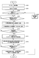
- FIG. 3 is a flowchart showing processing of the photographing method according to the present embodiment.
- the process of FIG. 3 is controlled by the CPU 1281 of the control circuit 128.
- the processing of FIG. 3 is based on the premise that the mode of the imaging apparatus 100 is set to the imaging mode.
- the photographing apparatus 100 may have a mode other than the photographing mode such as a reproduction mode for reproducing image data.
- step S100 the CPU 1281 continuously operates the imaging circuit 114, processes live view image data obtained by the continuous operation of the imaging circuit 114 in the image processing circuit 1284, and thereafter processes the live view image data processed by the display element driving circuit 120.
- the display element driving circuit 120 displays the imaging result of the imaging circuit 114 on the display element 118 in real time based on the input live view image data. By viewing the live view image displayed by the live view operation, the user can confirm the composition and the like.
- the user selects an operation mode of the photographing apparatus 100 (step S102).
- the operation mode is selected by operating the operation button 1301 or the touch panel 122, for example.
- the CPU 1281 determines whether or not the composition guide mode is selected as the operation mode (step S104).
- step S106 the CPU 1281 determines whether or not a shooting start instruction as a first instruction has been detected.
- the shooting start instruction is, for example, a pressing operation of the release button 1302 or a touch release operation using the touch panel 122.
- the CPU 1281 stands by until an instruction to start shooting is detected in step S106. Note that the processing may return to step S100 when a predetermined time has elapsed without detection of an instruction to start shooting.
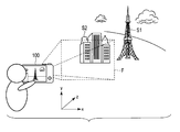
- FIG. 4 shows an example at the time of confirmation in the composition guide mode.
- the user holding the photographing apparatus 100 finds a desired composition while moving the photographing apparatus 100 in the x, y, and z directions.
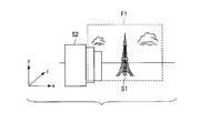
- the desired composition is a state in which the subject (for example, subject S1) that the user intends to photograph is arranged at a desired position of the user within the angle of view F1 of the photographing apparatus 100 as shown in FIG. Shall be said.
- the z direction is a direction along the optical axis of the imaging apparatus 100.
- the x direction is a surface direction perpendicular to the optical axis and parallel to the ground surface.
- the y direction is a surface direction perpendicular to the optical axis and a direction perpendicular to the ground surface.
- 6A to 6D show a concept of composition change, that is, framing.
- the subject S1 is displayed as shown in FIG. 6B.
- 6A when the user moves the photographing apparatus 100 in the + x direction, the subject S1 moves in the ⁇ x direction within the field angle F1, as shown in FIG. 6C.
- 6A when the user moves the photographing apparatus 100 in the + z direction or performs a zooming operation on the telephoto side, the subject S1 is enlarged as shown in FIG. 6D. In this way, the user can place the subject S1 at a predetermined position within the angle of view by moving the photographing apparatus 100 by the user.
- an instruction to start shooting is given as a first instruction when the desired shooting conditions are met. For example, it is assumed that the user gives an instruction to start photographing in the composition shown in FIG. 7 (corresponding to FIG. 6A).
- the CPU 1281 interrupts the live view operation and starts the shooting operation by the imaging circuit 114.
- the CPU 1281 operates the imaging circuit 114 in accordance with the shooting parameters set by the user, and obtains image data (first shot image data) as a first shot image.
- the CPU 1281 processes the first captured image data in the image processing circuit 1284, and records the processed first captured image data on the recording medium 126 (step S108).
- the CPU 1281 After the photographing operation, the CPU 1281 generates at least one sample image data from the first photographed image data by the image processing circuit 1284. Thereafter, the CPU 1281 inputs the first photographed image data and sample image data to the display element driving circuit 120, and the first photographed image based on the first photographed image data and the sample image based on the sample image data are input to the display element 118. It is displayed (step S110).
- FIG. 8 shows a concept of generation of sample image data.
- FIG. 8 shows a concept of generation of sample image data for framing.
- Sample image data for framing refers to image data that is assumed to have been acquired by framing different from the framing at the time of acquiring the first captured image data.
- Such sample image data is obtained by trimming the image data in the composition frame f by the image processing circuit 1284 in a state where the subject is arranged at a predetermined position of the composition frame f set in the first photographed image data.
- the subject is, for example, a subject at the focus position.
- the composition frame f is composed of, for example, three equal dividing lines in the horizontal direction and the vertical direction, and has a predetermined aspect ratio.
- Trimming is performed, for example, on image data in a state where a subject is arranged at intersections P1, P2, P3, and P4 of the third dividing line.
- sample image data i1 shown in FIG. 9A is generated.
- sample image data i2 shown in FIG. 9B is generated.
- sample image data i3 shown in FIG. 9C is generated.
- sample image data i4 illustrated in FIG. 9D is generated.
- image data generated in this way is also subjected to reduction processing for display.
- reduction processing for display is also performed on the first captured image data.
- the third dividing line is used for generating the sample image data.
- the method for generating sample image data is not limited to this.
- the composition frame f a frame composed of generally known composition lines such as a golden dividing line and a triangular composition line may be used.
- the aspect ratio of the region to be trimmed may be an aspect ratio generally used for a photograph such as 16: 9, 3: 2, 1: 1, or the like.
- the subject is the subject at the focus position.
- the subject may be determined using a known feature extraction technique such as face detection.
- FIG. 10 is a diagram illustrating a display example of the first photographed image and the sample image.
- a reduced image I1 of the first photographed image is displayed at the upper left corner of the display element 118 (touch panel 122), and reduced images i1 to i4 of a plurality of example images are displayed as tiles at the lower left corner of the screen. I am letting.
- the user is aware of variations with respect to framing.
- the reduced image of the sample image is displayed in a tile shape, but the display method of the sample image is not limited to this.
- the display method of the sample image is not limited to this.
- the number of sample images is large, only a part of the sample images may be displayed and displayed so as to be switched to another sample image when a predetermined time elapses or by a user operation.
- the image may be displayed one by one on the entire screen of the display element 118 without reducing the image. In this case, images are sequentially displayed when a predetermined time elapses or by a user operation.
- a plurality of sample image data is generated from the first captured image data, but only one sample image data may be generated. In this case, the determination in the next step S112 is not necessary.
- the user selects a desired sample image.
- This selection as the second instruction is performed by operating the operation button 1301 or the touch panel 122, for example.
- the CPU 1281 determines whether any one of the sample images has been selected by the user (step S112). The CPU 1281 waits until a sample image is selected in step S112. If it is determined that no sample image has been selected, the process may proceed to step S118.
- the CPU 1281 controls the display element driving circuit 120 so that the selected sample image is displayed in a thick frame as shown in FIG. 11, for example.
- FIG. 11 shows a display example when the sample image i1 is selected.
- the CPU 1281 After displaying the thick frame, the CPU 1281 generates guide information corresponding to the selected sample image i1. After the guide information is generated, the CPU 1281 resumes the live view operation. Thereafter, the CPU 1281 inputs the guide information to the display element driving circuit 120 and causes the display element 118 to display the guide information together with the live view image (step S114).
- step S114 a process for displaying guide information for framing will be described.
- the CPU 1281 resumes the live view operation and acquires live view image data.
- the CPU 1281 calculates a matching area between the acquired live view image data and the selected sample image data.
- a known technique such as template matching can be used as a method for finding a matching area between image data.
- the CPU 1281 After calculating the matching area, the CPU 1281 generates guide information based on the matching area. That is, the CPU 1281 obtains the coordinates of the matching area corresponding to the sample image data in the live view image data as the guide information. Thereafter, the CPU 1281 inputs guide information to the display element driving circuit 120 to display the guide information.
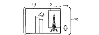
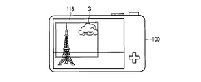
- FIGS. 12A to 12D show display examples of guide information.
- the guide information is displayed to allow the user to recognize the position of the sample image in the live view image.
- a frame image G indicating the region of the sample image is displayed. Is done.
- the CPU 1281 detects the movement of the photographing apparatus 100 by the movement detection circuit 1285. Then, the CPU 1281 changes the display position of the guide information G according to the movement of the photographing apparatus 100. In addition, the CPU 1281 detects a zooming operation by the user, and sends an instruction to the lens driving circuit 104 to change the focal length of the photographing lens 102 in accordance with the detected zooming operation. Then, the CPU 1281 changes the display position of the guide information G according to the change in the angle of view of the live view image accompanying such a change in the focal length (step S116).
- FIG. 12A shows guide information G displayed immediately after the first captured image is obtained.
- the coordinates of the matching area corresponding to the sample image data in the live view image data change.
- the display position of the guide information G also changes.
- 12B shows a guide information display state when the user moves the photographing apparatus 100 in the ⁇ x direction
- FIG. 12C shows a guide information display state when the user moves the photographing apparatus 100 in the + x direction.
- FIG. 12D shows a display state of guide information when the user moves the photographing apparatus 100 in the + z direction or performs a zooming operation on the telephoto side.
- the guide information G is not displayed.
- the guide information in the present embodiment only indicates the framing state of the sample image. Therefore, even when the live view image changes due to framing, the guide information G is displayed as if it is stuck to the subject.
- the user changes other shooting conditions such as shooting parameters such as aperture and shutter speed and image processing parameters such as white balance setting as necessary. You may do it.
- the CPU 1281 determines whether or not an imaging start instruction has been detected (step S118).
- the shooting start instruction is, for example, a pressing operation of the release button 1302 or a touch release operation using the touch panel 122, as described above.
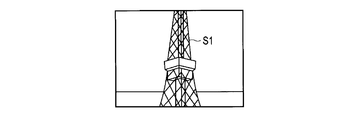
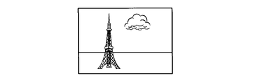
- the user gives an instruction to start shooting while operating the shooting apparatus 100 and when the desired shooting conditions are met. For example, it is assumed that the user has noticed from the guide information G in FIG. 12C that the framing is “eliminating a disturbing background by approaching the subject”. In this case, the user resets the framing as shown in FIG. 13A so as to capture the entire image of the subject he / she wants to shoot, and instructs the start of shooting.
- step S118 If it is determined in step S118 that an instruction to start shooting has not been detected, the CPU 1281 returns the process to step S116. If it is determined in step S118 that an instruction to start shooting has been detected, the CPU 1281 starts the shooting operation by the imaging circuit 114. In this shooting operation, the CPU 1281 operates the imaging circuit 114 in accordance with the shooting parameters set by the user, and obtains image data (second shot image data) as a second shot image. Then, the CPU 1281 processes the second captured image data in the image processing circuit 1284, and records the processed second captured image data in the recording medium 126 as an image file associated with the first captured image data (step S120). Thereafter, the CPU 1281 ends the process of FIG. With such a photographing operation, a second photographed image as shown in FIG. 13B is recorded on the recording medium 126. The second photographed image shown in FIG. 13B is an image photographed by the user by performing framing with reference to the sample image.
- step S122 When it is determined in step S104 that the composition guide mode is not set as the operation mode, that is, the normal shooting mode is set, the CPU 1281 performs the normal shooting mode processing (step S122). Processing in the normal shooting mode is the same as in the conventional shooting mode. Therefore, it will be briefly described. That is, when an instruction to start shooting is given by the user, the CPU 1281 operates the imaging circuit 114 according to the shooting parameters set by the user to obtain captured image data. Then, the CPU 1281 processes the captured image data in the image processing circuit 1284 and records the processed captured image data in the recording medium 126 as an image file. After the normal shooting mode processing, the CPU 1281 ends the processing of FIG.
- an example image generated from the first photographed image photographed by the user with intention is presented to the user.
- the user can obtain awareness of framing, for example, by comparing the first captured image with the sample image.
- the guide information corresponding to the sample image selected by the user is displayed on the display element 118 together with the live view image, so that the user can directly reflect the awareness obtained by the sample image in the next shooting. Can do.
- the user's photographing technique can be improved.
- the guide information for the framing may be generated by detecting the change amount of the posture of the photographing apparatus 100 while the live view image before photographing of the second photographed image is displayed by the motion sensor 134. .
- This guide information is obtained by converting the amount of change in posture detected by the motion sensor 134 into the amount of movement on the image.
- a frame image indicating the region of the sample image is displayed as guide information for framing.
- the frame image G may be displayed only at the vertex of the region of the sample image.
- the frame image G may be displayed semi-transparently.
- the guide information may be displayed only for a predetermined time after the live view image before the second captured image is displayed.
- sample image data created in the first embodiment described above is image data having a composition different from that of the first photographed image data.
- the method for generating sample image data is not limited to this.
- the sample image data may be generated by adding not only a composition change but also a change related to picture making such as white balance.
- the sample image is displayed on the display element 118 of the photographing apparatus 100.
- the first captured image data is transmitted to the external device 200 via the wireless communication circuit 136, so that sample image data is created in the external device 200 or the display of the external device 200 is displayed.
- a sample image can also be displayed on the element.
- the same guide information as in the first embodiment described above is displayed according to the sample image selected from the sample images displayed on the display element of the external device 200.
- sample image data for angle change (rotation in the pitch direction) with respect to the subject is generated.
- 15A and 15B are diagrams showing the change of the angle.
- the change of the angle in the present embodiment is performed, for example, from a state where the optical axis of the photographing apparatus 100 is oriented in a horizontal direction with respect to the ground surface as shown in FIG. 15A, and as shown in FIG. 15B. Is inclined with respect to the ground surface (a state in which the photographing apparatus 100 is moved in the pitch direction).
- the sample image data as shown in FIG. 15B is generated by projective transformation of each area of the first captured image data, for example. That is, corresponding image data is generated by projective transformation when the first captured image data is rotated in the pitch direction by a predetermined rotation angle. This rotation angle is a rotation angle in the pitch direction with reference to when the photographing apparatus 100 is horizontally arranged. Based on the sample image data generated in this way, the sample image as shown in step S110 of FIG. 3 is displayed.
- FIG. 16 is an example of guide information in the second embodiment.
- a square image G1 corresponding to a change in angle with respect to the sample image is displayed on the display element 118 as guide information.
- the length of the short side of the trapezoid shown in FIG. 16 is determined according to the difference between the rotation angle of the selected sample image data and the rotation angle (posture change in the pitch direction) of the photographing apparatus 100 when the live view image is displayed. Is done. That is, the length of the short side decreases as the difference in the rotation angle increases.
- FIG. 17A and FIG. 17B show the change of the guide information.
- FIG. 17A shows guide information displayed when the photographing apparatus 100 is held horizontally with respect to the ground surface.
- the guide information G1 since the difference between the rotation angle at which the sample image selected by the user is obtained and the rotation angle of the photographing apparatus 100 when the live view image is displayed is large, the guide information G1 has a trapezoidal shape.
- the rotation angle at which the sample image selected by the user is obtained and the rotation angle of the photographing apparatus 100 when the live view image is displayed is displayed.
- the difference becomes smaller, and the guide information G1 approaches a rectangle as shown in FIG. 17B.
- an image equivalent to the image shown in FIG. 15B is taken.
- the user can be aware of the angle change by comparing the first captured image with the sample image.
- the user can sensibly grasp the angle for capturing an image equivalent to the sample image while viewing the live view image. Will be able to.
- the guide information not only the square image G1 but also the rotation axis G2 of rotation that can obtain the sample image as shown in FIG. 17B may be displayed together.
- the method of indicating the degree of angle change is not limited to changing the shape of a rectangular image.
- the normal line of the sample image surface for the live view image may be displayed, or a rotation arrow or the like corresponding to the amount of change in angle may be displayed.
- an arrow image G3 indicating the normal line of the sample image surface may be displayed in accordance with the change of the rectangular image G1.
- the arrow image G3 changes from the state of FIG. 18A as shown in FIG. 18B. That is, the arrow image G3 changes in a direction perpendicular to the user.
Landscapes
- Engineering & Computer Science (AREA)
- Multimedia (AREA)
- Signal Processing (AREA)
- Human Computer Interaction (AREA)
- Studio Devices (AREA)
- Indication In Cameras, And Counting Of Exposures (AREA)
Abstract
撮影装置(100)は、被写体像から画像データを取得する撮像回路(114)と、画像データに基づいて画像を表示する表示素子(118)と、撮影装置に対して指示を与える操作部材(130)と、撮像回路(114)で取得された画像データに基づいてライブビュー画像を表示素子(118)に表示させるとともに、操作部材(130)から第1指示が与えられたときに、撮像回路(114)に第1撮影画像データを取得させ、第1撮影画像データに基づいて少なくとも1つの作例画像データを生成し、生成した作例画像データに基づいてガイド情報を生成し、生成したガイド情報をライブビュー画像とともに表示素子(118)に表示させる制御回路(128)とを備える。
Description
本発明は、使用者に適切な内容を提示して使用者の撮影行為を支援する撮影装置及びそれを用いた撮影方法に関する。
近年、撮影時の構図の設定をアシストする機能を有する撮影装置に関する提案がなされている。例えば、米国特許出願公開第2013/0293746号明細書の表示制御装置は、撮像の結果としてフレームメモリに記憶された原画像データに基づいて、互いに構図の異なる複数の補助画像データを生成し、生成した補助画像データに基づく複数の補助画像を表示素子に表示させるようにしている。さらに、米国特許出願公開第2013/0293746号明細書の表示制御装置は、個々の補助画像を使用者が撮影するために必要な撮像回路の移動方向を示す矢印を表示させるようにしている。また、日本国特開2013-183306号公報の撮影装置は、撮像の結果として得られたライブ画像における主要被写体と他の被写体とをそれぞれ認識し、認識した主要被写体と他の被写体との位置関係、それぞれの占有面積、占有面積比に基づいて所定の構図条件を満足するような構図となる構図枠の検知を行うようにしている。そして、日本国特開2013-183306号公報の撮影装置は、構図枠の検知を行うことができた場合に、所定の構図条件にするための撮影装置の移動方向を示す移動マークをライブ画像に重ねて表示させるようにしている。
米国特許出願公開第2013/0293746号明細書及び日本国特開2013-183306号公報は、何れも撮影装置で自動的に判断された正解の構図となるように使用者を導く技術である。この場合、使用者は、自分自身で構図を考える余地が少なく、使用者自身のスキルアップについて気付きを得ることができないことがある。
本発明は、前記の事情に鑑みてなされたもので、使用者自身のスキルアップを期待できるように使用者の撮影行為を支援する撮影装置及びそれを用いた撮影方法を提供することを目的とする。
前記の目的を達成するために、本発明の第1の態様の撮影装置は、被写体像から画像データを取得する撮像回路と、前記画像データに基づいて画像を表示する表示素子と、撮影装置に対して指示を与える操作部材と、前記撮像回路でライブビュー画像データとして取得された画像データに基づいてライブビュー画像を前記表示素子に表示させるとともに、前記操作部材から前記指示としての第1指示が与えられたときに、前記撮像回路に第1撮影画像データとしての前記画像データを取得させ、前記第1撮影画像データに基づいて少なくとも1つの作例画像データを生成し、生成した前記作例画像データに基づいてガイド情報を生成し、生成した前記ガイド情報を前記ライブビュー画像とともに前記表示素子に表示させる制御回路とを具備することを特徴とする。
前記の目的を達成するために、本発明の第2の態様の撮影方法は、撮像回路により、被写体像から画像データを取得することと、前記撮像回路でライブビュー画像データとして取得された画像データに基づいてライブビュー画像を表示素子に表示させることと、操作部材からの第1指示が与えられたときに、前記撮像回路に第1撮影画像データとしての前記画像データを取得させることと、前記第1撮影画像データに基づいて少なくとも1つの作例画像データを生成することと、前記作例画像データに基づいてガイド情報を生成することと、前記ガイド情報を前記ライブビュー画像とともに前記表示素子に表示させることとを具備することを特徴とする。
本発明によれば、使用者自身のスキルアップを期待できるように使用者の撮影行為を支援する撮影装置及びそれを用いた撮影方法を提供することができる。
以下、図面を参照して本発明の実施形態を説明する。
[第1の実施形態]
まず、本発明の第1の実施形態について説明する。図1は、本発明の各実施形態に係る撮影装置の一例としての構成を示す図である。図2は、一例の撮影装置の外観図である。
[第1の実施形態]
まず、本発明の第1の実施形態について説明する。図1は、本発明の各実施形態に係る撮影装置の一例としての構成を示す図である。図2は、一例の撮影装置の外観図である。
図1に示す撮影装置100は、撮影レンズ102と、レンズ駆動回路104と、絞り106と、絞り駆動回路108と、シャッタ110と、シャッタ駆動回路112と、撮像回路114と、揮発性メモリ116と、表示素子118と、表示素子駆動回路120と、タッチパネル122と、タッチパネル検出回路124と、記録媒体126と、制御回路128と、操作部材130と、不揮発性メモリ132と、動きセンサ134と、無線通信回路136とを有している。
撮影レンズ102は、図示しない被写体からの撮影光束を、撮像回路114の受光面上に導くための光学系である。この撮影レンズ102は、フォーカスレンズ等の複数のレンズを有しており、またズームレンズとして構成されていても良い。レンズ駆動回路104は、モータ及びその駆動回路等を有している。このレンズ駆動回路104は、制御回路128内のCPU1281の制御に従って、撮影レンズ102を構成している各種のレンズをその光軸方向(図示一点鎖線方向)に駆動させる。
絞り106は、開閉自在に構成され、撮影レンズ102を介して撮像回路114に入射する撮影光束の量を調整する。絞り駆動回路108は、絞り106を駆動するための駆動回路を有している。この絞り駆動回路108は、制御回路128内のCPU1281の制御に従って絞り106を駆動させる。
シャッタ110は、撮像回路114の受光面を遮光状態又は露光状態とするように構成されている。このシャッタ110により、撮像回路114の露光時間が調整される。シャッタ駆動回路112は、シャッタ110を駆動させるための駆動回路を有し、制御回路128内のCPU1281の制御に従ってシャッタ110を駆動させる。
撮像回路114は、撮影レンズ102を介して集光された被写体からの撮影光束が結像される受光面を有している。撮像回路114の受光面は、複数の画素が2次元状に配置されて構成されており、また、受光面の光入射側には、カラーフィルタが設けられている。このような撮像回路114は、受光面に結像された撮影光束に対応した像(被写体像)を、その光量に応じた電気信号(以下、画像信号という)に変換する。また、撮像回路114は、制御回路128内のCPU1281の制御に従って、画像信号に対してCDS(相関二重サンプリング)処理やAGC(自動利得制御)処理等のアナログ処理を施す。さらに、撮像回路114は、アナログ処理した画像信号をデジタル信号(以下、画像データという)に変換する。
揮発性メモリ116は、ワークエリアを記憶エリアとして有している。ワークエリアは、撮像回路114で得られた画像データ等の、撮影装置100の各回路で発生したデータを一時記憶しておくために揮発性メモリ116に設けられた記憶エリアである。
表示素子118は、例えば液晶ディプレイ(LCD)であり、ライブビュー用の画像(ライブビュー画像)及び記録媒体126に記録された画像等の各種の画像を表示する。表示素子駆動回路120は、制御回路128のCPU1281から入力された画像データに基づいて表示素子118を駆動させ、表示素子118に画像を表示させる。
タッチパネル122は、表示素子118の表示画面上に一体的に形成されており、表示画面上への使用者の指等の接触位置等を検出する。タッチパネル検出回路124は、タッチパネル122を駆動するとともに、タッチパネル122からの接触検出信号を制御回路128のCPU1281に出力する。CPU1281は、接触検出信号から、使用者の表示画面上への接触操作を検出し、その接触操作に応じた処理を実行する。
記録媒体126は、例えばメモリカードであり、撮影動作によって得られた画像ファイルが記録される。画像ファイルは、撮影動作によって得られた画像データに所定のヘッダを付与して構成されるファイルである。画像ファイルには、撮影動作によって得られた画像データの他に、作例画像データ、ガイド情報も記録され得る。作例画像データは、使用者の意図により撮影された画像データに基づいて生成される、他の撮影条件の画像データである。ここでの撮影条件とは、例えば構図の変更(フレーミング)の条件が挙げられる。また、ガイド情報は、ユーザが作例画像と同様の画像を撮影したいと希望した場合に、その撮影をガイドするための情報である。例えば、フレーミングの条件を変更することによって作例画像データが生成された場合、ガイド情報は、作例画像と同様の画像を撮影するために必要となる撮影装置100の移動方向をユーザに対して認識させるための情報である。
制御回路128は、撮影装置100の動作を制御するための制御回路であり、CPU1281と、AE回路1282と、AF回路1283と、画像処理回路1284と、動き検出回路1285とを有している。
CPU1281は、レンズ駆動回路104、絞り駆動回路108、シャッタ駆動回路112、撮像回路114、表示素子駆動回路120、タッチパネル検出回路124等の制御回路128の外部の各ブロック、及び制御回路128の内部の各制御回路の動作を制御する。また、CPU1281は、前述のガイド情報を生成する処理も行う。ガイド情報の生成処理の詳細は後で説明する。
AE回路1282は、AE処理を制御する。より詳しくは、AE回路1282は、撮像回路114で得られた画像データを用いて被写体輝度を算出する。CPU1281は、この被写体輝度に従って、露光時の絞り106の開口量(絞り値)、シャッタ110の開放時間(シャッタ速度値)、撮像素子感度等を算出する。
AF回路1283は、撮像画面内の焦点状態を検出してAF処理を制御する。より詳しくは、AF回路1283は、画像データから算出されるAF評価値に従って画像データのコントラストを評価しつつ、レンズ駆動回路104を制御してフォーカスレンズを合焦状態とする。このようなAF処理は、コントラスト方式等と呼ばれる。AF処理として位相差方式が用いられても良い。
画像処理回路1284は、画像データに対する各種の画像処理を行う。画像処理としては、ホワイトバランス補正処理、色補正処理、ガンマ(γ)補正処理、拡大・縮小処理、圧縮処理等が含まれる。また、画像処理回路1284は、圧縮されている画像データに対する伸張処理も施す。さらに、画像処理回路1284は、前述した作例画像データを生成する処理も行う。作例画像データの生成処理の詳細は後で説明する。
動き検出回路1285は、撮影装置100の動きを検出する。撮影装置100の動きは、例えば複数フレームの画像データを用いた動きベクトル検出又は動きセンサ134の出力に基づいて検出される。
操作部材130は、使用者によって操作される各種の操作部材である。操作部材130としては、例えば、操作ボタン1301、レリーズボタン1302、モードダイヤル1303、ズームスイッチ1304等が含まれる。操作ボタン1301は、例えば図2に示すように撮影装置100の背面に設けられている。この操作ボタン1301は、例えばメニュー画面上での項目の選択や決定をするための操作部材として用いられる。レリーズボタン1302は、例えば図2に示すように撮影装置100の上面に設けられている。このレリーズボタン1302は、静止画撮影の指示をするための操作部材である。モードダイヤル1303は、例えば図2に示すように撮影装置100の上面に設けられている。このモードダイヤル1303は、撮影装置100の撮影設定を選択するための操作部材である。撮影設定は、例えば動作モードの設定である。動作モードは、通常撮影モードと構図ガイドモードとを含む。通常撮影モードは、ガイド情報の表示がない状態で撮影が行われるモードである。この通常撮影モードでは、絞り優先撮影、シャッタ優先撮影、プログラム撮影、マニュアル撮影といった従来知られた方法で撮影が行われる。一方、構図ガイドモードは、ガイド情報の表示がある状態で撮影が行われるモードである。ズームスイッチ1304は、使用者がズーミング操作をするためのスイッチである。
不揮発性メモリ132は、CPU1281が種々の処理を実行するためのプログラムコードを記憶している。また、不揮発性メモリ132は、撮影レンズ102、絞り106、及び撮像回路114等の動作に必要な制御パラメータ、並びに画像処理回路1284での画像処理に必要な制御パラメータ等の、各種の制御パラメータを記憶している。
動きセンサ134は、角速度センサ1341と姿勢センサ1342とを含む。角速度センサ1341は、例えばジャイロセンサであり、撮影装置100に発生した3軸周りの角速度を検出する。姿勢センサ1342は、例えば3軸加速度センサであり、撮影装置100に発生した加速度を検出する。
無線通信回路136は、例えば無線LAN通信回路であり、撮影装置100と外部機器200との通信の際の処理を行う。外部機器200は、例えばスマートフォンである。
以下、本実施形態に係る撮影装置100を用いた撮影方法について説明する。図3は、本実施形態に係る撮影方法の処理を示すフローチャートである。図3の処理は、制御回路128のCPU1281によって制御される。ここで、図3の処理は、撮影装置100のモードが撮影モードに設定されていることを前提としている。撮影装置100は、画像データを再生するための再生モード等の撮影モード以外の他のモードを有していても良い。
図3の処理は、例えば撮影装置100の電源がオンされたときに開始される。図3の処理が開始されると、CPU1281は、ライブビュー動作を開始させる(ステップS100)。すなわち、CPU1281は、撮像回路114を連続動作させ、撮像回路114の連続動作によって得られるライブビュー画像データを画像処理回路1284において処理し、その後に処理されたライブビュー画像データを表示素子駆動回路120に入力する。表示素子駆動回路120は、入力されたライブビュー画像データに基づいて、撮像回路114の撮像結果を表示素子118にリアルタイム表示させる。ライブビュー動作によって表示されるライブビュー画像を見ることにより、使用者は、構図の確認等を行うことができる。
ライブビュー動作中に使用者は、撮影装置100の動作モードを選択する(ステップS102)。動作モードは、例えば操作ボタン1301の操作又はタッチパネル122の操作によって選択される。このような動作モードの選択の後、CPU1281は、動作モードとして構図ガイドモードが選択されているか否かを判定する(ステップS104)。
ステップS104において動作モードとして構図ガイドモードが選択されていると判定した場合に、CPU1281は、第1指示としての撮影開始指示が検知されたか否かを判定する(ステップS106)。撮影開始指示は、例えばレリーズボタン1302の押操作、タッチパネル122を用いたタッチレリーズ操作である。ステップS106において撮影開始の指示が検知されるまで、CPU1281は待機する。なお、撮影開始の指示が検知されずに所定時間が経過した場合に、処理がステップS100に戻るようにしても良い。
図4は、構図ガイドモード中の確認時の一例を示している。構図ガイドモードにおいて、撮影装置100を構えている使用者は、撮影装置100をx、y、z方向に動かしながら所望の構図を見つける。所望の構図とは、使用者が撮影しようとしている被写体(例えば被写体S1)が、図5に示すように、撮影装置100の画角F1内の使用者の所望の位置に配置された状態のことを言うものとする。また、z方向は、撮影装置100の光軸に沿った方向である。また、x方向は、光軸に対して垂直な面方向であって、地表に対して平行な方向である。y方向は、光軸に対して垂直な面方向であって、地表に対して垂直な方向である。
図6Aから図6Dは、構図の変更、すなわちフレーミングの概念を示している。例えば図6Aのように被写体S1が画角F1の中央付近に位置している状態に対し、使用者が撮影装置100を-x方向に動かした場合、図6Bに示すように、被写体S1は画角F1内の+x方向に移動する。また、図6Aの状態に対し、使用者が撮影装置100を+x方向に動かした場合、図6Cに示すように、被写体S1は画角F1内の-x方向に移動する。さらに、図6Aの状態に対し、使用者が撮影装置100を+z方向に動かした場合又は望遠側のズーミング操作をした場合、図6Dに示すように、被写体S1は拡大される。このように、使用者が撮影装置100を動かすことにより、被写体S1を画角内の所定の位置に配置することができる。
以上のようなフレーミングとともに、使用者は、必要に応じて、絞りやシャッタ速といった撮影パラメータ、ホワイトバランス設定等の画像処理パラメータといった他の撮影条件を変更したりする。そして、所望の撮影条件となったときに第1指示としての撮影開始の指示を行う。例えば、使用者は、図7で示す構図(図6Aに対応)のときに撮影開始の指示を行ったとする。
ステップS106において撮影開始の指示が検知されたと判定したときに、CPU1281は、ライブビュー動作を中断し、撮像回路114による撮影動作を開始させる。撮影動作では、CPU1281は、使用者によって設定された撮影パラメータに従って撮像回路114を動作させ、第1撮影画像としての画像データ(第1撮影画像データ)を得る。そして、CPU1281は、画像処理回路1284において第1撮影画像データを処理し、処理された第1撮影画像データを記録媒体126に記録させる(ステップS108)。
撮影動作の後、CPU1281は、画像処理回路1284によって第1撮影画像データから少なくとも1つの作例画像データを生成する。その後、CPU1281は、第1撮影画像データと作例画像データとを表示素子駆動回路120に入力し、第1撮影画像データに基づく第1撮影画像と作例画像データに基づく作例画像とを表示素子118に表示させる(ステップS110)。
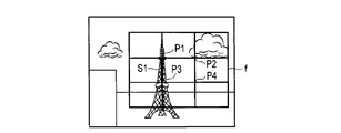
ステップS110の処理についてさらに説明する。図8は、作例画像データの生成の概念を示している。ここで、図8は、フレーミングに対する作例画像データの生成の概念を示している。フレーミングに対する作例画像データとは、第1撮影画像データを取得したときのフレーミングとは異なるフレーミングで取得したことを想定した画像データのことをいう。このような作例画像データは、第1撮影画像データ内に設定される構図枠fの所定位置に被写体を配置した状態で構図枠f内の画像データを画像処理回路1284によってトリミングすることによって得られる。ここで、被写体は、例えばフォーカス位置の被写体である。また、構図枠fは、例えば水平方向及び垂直方向の3等分割線によって構成されており、所定のアスペクト比を有している。
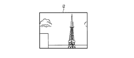
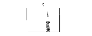
トリミングは、例えば3等分割線の交点P1、P2、P3、P4に被写体を配置した状態の画像データに対して行われる。被写体を点P1に配置した状態でトリミングが行われた場合、図9Aに示す作例画像データi1が生成される。また、被写体を点P2に配置した状態でトリミングが行われた場合、図9Bに示す作例画像データi2が生成される。また、被写体を点P3に配置した状態でトリミングが行われた場合、図9Cに示す作例画像データi3が生成される。また、被写体を点P4に配置した状態でトリミングが行われた場合、図9Dに示す作例画像データi4が生成される。このようにして生成された作例画像データに対しては、表示のための例えば縮小処理も行われる。また、第1撮影画像データに対しても、表示のための例えば縮小処理も行われる。
本実施形態では、作例画像データの生成に3等分割線を利用している。しかしながら、作例画像データの生成のための手法はこれに限定されるものではない。例えば、構図枠fとして、黄金分割線や三角構図線等の一般的に知られる構図線によって構成される枠が用いられても良い。また、トリミングする領域のアスペクト比も16:9、3:2、1:1等の一般的に写真に用いられるアスペクト比が利用され得る。
また、本実施形態では、被写体をフォーカス位置の被写体としている。被写体をフォーカス位置によって決定するのではなく、顔検出等の周知の特徴抽出技術を用いて決定しても良い。
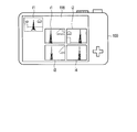
図10は、第1撮影画像と作例画像の表示例を示す図である。一例では、図10に示すように、第1撮影画像の縮小画像I1を表示素子118(タッチパネル122)の画面左上端に表示させ、複数の作例画像の縮小画像i1~i4を画面左下にタイル表示させている。このように、第1撮影画像と作例画像とを同時に表示させることで、使用者は、フレーミングに対するバリエーションの気付きを得る。
本実施形態では、作例画像の縮小画像をタイル状に表示させているが、作例画像の表示手法はこれに限定されるものではない。例えば、作例画像の枚数が多い場合には、その一部のみを表示させ、所定時間の経過時又は使用者の操作によって別の作例画像に切り替えるように表示をさせても良い。また、第1撮影画像と作例画像とで又は作例画像同士で、画像領域の一部を重ならせように表示させるようにしても良い。さらに、画像を縮小せずに、表示素子118の画面全体に1枚ずつ表示させるようにしても良い。この場合、所定時間の経過時又は使用者の操作によって順次に画像を表示させる。
また、本実施形態では、第1撮影画像データから複数の作例画像データを生成しているが、作例画像データを1つのみ生成するようにしても良い。この場合、次のステップS112の判定は不要である。
ここで、図3の説明に戻る。図10のような表示がされた後、使用者は、所望の作例画像を選択する。第2指示としてのこの選択は、例えば操作ボタン1301の操作又はタッチパネル122の操作によって行われる。使用者による作例画像の選択の間、CPU1281は、使用者によって、作例画像の何れかが選択されたか否かを判定する(ステップS112)。ステップS112において作例画像が選択されるまで、CPU1281は待機する。なお、作例画像が選択されていないと判定された場合に、処理がステップS118に移行するようにしても良い。
ステップS112において作例画像が選択されたと判定した場合に、CPU1281は、選択された作例画像を、例えば図11で示すように、太枠表示させるように表示素子駆動回路120を制御する。図11は、作例画像i1が選択されたときの表示例を示している。太枠表示の後、CPU1281は、選択された作例画像i1に対応したガイド情報を生成する。ガイド情報の生成後、CPU1281は、ライブビュー動作を再開する。その後、CPU1281は、ガイド情報を表示素子駆動回路120に入力し、ライブビュー画像と併せてガイド情報を表示素子118に表示させる(ステップS114)。
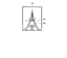
ステップS114の処理について説明する。ここでは、一例として、フレーミングに対するガイド情報を表示させる処理について説明する。まず、CPU1281は、ライブビュー動作を再開させてライブビュー画像データを取得する。続いて、CPU1281は、取得したライブビュー画像データと選択された作例画像データとの一致領域を算出する。画像データ間の一致領域を見つける手法としては、テンプレートマッチング等の周知の技術が利用され得る。一致領域の算出後、CPU1281は、一致領域に基づいてガイド情報を生成する。すなわち、CPU1281は、ガイド情報として、ライブビュー画像データ内の作例画像データと対応する一致領域の座標を求める。その後、CPU1281は、ガイド情報を表示素子駆動回路120に入力させてガイド情報を表示させる。図12A~図12Dは、ガイド情報の表示例を示している。図12A~図12Dに示すように、ガイド情報の表示は、ライブビュー画像内の作例画像の位置を使用者に認識させるための表示であって、例えば作例画像の領域を示す枠画像Gを表示することにより行われる。
ここで、図3の説明に戻る。ガイド情報Gが表示されている間、CPU1281は、動き検出回路1285によって撮影装置100の動きを検出する。そして、CPU1281は、撮影装置100の動きに従って、ガイド情報Gの表示位置を変更する。また、CPU1281は、使用者によるズーミング操作を検出し、検出したズーミング操作に応じて撮影レンズ102の焦点距離を変化させるようにレンズ駆動回路104に指示を送る。そして、CPU1281は、このような焦点距離の変更に伴うライブビュー画像の画角変更に応じて、ガイド情報Gの表示位置を変更する(ステップS116)。
ガイド情報Gが表示されている間に、使用者は、ガイド情報Gを参考にしつつ、撮影装置100をx、y、z方向に動かしながら所望の構図を見つける。例えば、図12Aは、第1撮影画像が得られた直後に表示されるガイド情報Gを示している。この状態で使用者が撮影装置100を動かすとライブビュー画像データ内の作例画像データと対応する一致領域の座標が変化する。したがって、図12B~図12Dで示すように、ガイド情報Gの表示位置も変化する。なお、図12Bは使用者が撮影装置100を-x方向に動かした場合のガイド情報の表示状態を示し、図12Cは使用者が撮影装置100を+x方向に動かした場合のガイド情報の表示状態を示し、図12Dは使用者が撮影装置100を+z方向に動かした場合又は望遠側のズーミング操作をした場合のガイド情報の表示状態を示している。図12Dに示すように、ライブビュー画像データ内に作例画像データと対応する一致領域の座標が存在しなくなった場合には、ガイド情報Gは表示されない。このように、本実施形態におけるガイド情報はあくまでも作例画像のフレーミング状態を示している。したがって、フレーミングによってライブビュー画像が変化したときであっても、ガイド情報Gはあたかも被写体に貼り付いているかのように表示される。
なお、第1撮影画像の撮影時と同様、フレーミングの変更とともに、使用者は、必要に応じて、絞りやシャッタ速といった撮影パラメータ、ホワイトバランス設定等の画像処理パラメータといった他の撮影条件を変更したりしても良い。
ここで、図3の説明に戻る。ガイド情報Gの表示位置の変更後、CPU1281は、撮影開始指示が検知されたか否かを判定する(ステップS118)。撮影開始指示は、前述と同様、例えばレリーズボタン1302の押し操作、タッチパネル122を用いたタッチレリーズ操作である。第1撮影画像の撮影時と同様に、使用者は、撮影装置100を操作しながら所望の撮影条件となったときに撮影開始の指示を行う。例えば、使用者は、図12Cのガイド情報Gから、「被写体に寄ることで邪魔な背景を無くす」というフレーミングに対する気付きを得たとする。この場合、使用者は自ら撮りたいと思った被写体の全体像が写るように図13Aに示すようにしてフレーミングを設定し直して撮影開始の指示をする。
ステップS118において撮影開始の指示が検知されていないと判定した場合に、CPU1281は、処理をステップS116に戻す。ステップS118において撮影開始の指示が検知されたと判定した場合に、CPU1281は、撮像回路114による撮影動作を開始させる。この撮影動作では、CPU1281は、使用者によって設定された撮影パラメータに従って撮像回路114を動作させ、第2撮影画像としての画像データ(第2撮影画像データ)を得る。そして、CPU1281は、画像処理回路1284において第2撮影画像データを処理し、処理された第2撮影画像データを第1撮影画像データと関連付けた画像ファイルとして記録媒体126に記録させる(ステップS120)。その後、CPU1281は、図3の処理を終了させる。このような撮影動作により、図13Bに示すような第2撮影画像が記録媒体126に記録される。図13Bに示す第2撮影画像は、使用者が作例画像を参考にしてフレーミングを行ったりして撮影した画像である。
ステップS104において動作モードとして構図ガイドモードが設定されていない、すなわち通常撮影モードが設定されていると判定した場合に、CPU1281は、通常撮影モードの処理を行う(ステップS122)。通常撮影モードの処理は、従来の撮影モードと同様である。したがって簡単に説明する。すなわち、使用者によって撮影開始の指示がなされたときに、CPU1281は、使用者によって設定された撮影パラメータに従って撮像回路114を動作させて撮影画像データを得る。そして、CPU1281は、画像処理回路1284において撮影画像データを処理し、処理された撮影画像データを画像ファイルとして記録媒体126に記録させる。通常撮影モードの処理の後、CPU1281は、図3の処理を終了させる。
以上説明したように第1の実施形態では、使用者が意思を持って撮影した第1撮影画像から生成された作例画像を使用者に提示している。これにより、使用者は第1撮影画像と作例画像とを見比べることで例えばフレーミングに対する気付きを得ることができる。また、使用者によって選択された作例画像に応じたガイド情報をライブビュー画像と併せて表示素子118に表示させることで、使用者は、作例画像によって得た気付きをそのまま次の撮影に反映させることができる。これによって、使用者の撮影技術の向上を図ることができる。
ここで、前述の第1の実施形態では、画像データ間の一致領域に基づいてフレーミングに対するガイド情報を生成する例を示している。これに対し、第2撮影画像の撮影前のライブビュー画像を表示している間の撮影装置100の姿勢の変化量を動きセンサ134によって検出することによって、フレーミングに対するガイド情報を生成しても良い。このガイド情報は、動きセンサ134によって検出した姿勢の変化量を画像上の移動量に換算したものとして得られる。
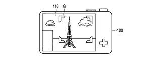
また、前述の第1の実施形態では、フレーミングに対するガイド情報として作例画像の領域を示す枠画像を表示させている。これに対し、例えば枠画像の代わりに、図14Aに示すように、作例画像の領域の頂点部にのみ枠画像Gを表示させるようにしても良い。また、図14Bに示すように、枠画像Gを半透明表示にしても良い。このように、フレーミングに対するガイド情報の表示手法は、種々変形ができるようになる。
また、ガイド情報は、第2撮影画像の撮影前のライブビュー画像が表示されてから所定の時間のみ表示させる等しても良い。
さらに、前述の第1の実施形態で作成される作例画像データは、第1撮影画像データに対して構図を異ならせた画像データである。しかしながら、作例画像データの生成手法はこれに限定されるものではない。例えば、構図変化だけでなく、ホワイトバランス等の絵作りに関わる変化も加えて作例画像データを生成しても良い。
また、前述した第1の実施形態では、作例画像は、撮影装置100の表示素子118に表示される。これに対し、図3のステップS110において、無線通信回路136を介して第1撮影画像データを外部機器200に送信することで、外部機器200において作例画像データを作成したり、外部機器200の表示素子に作例画像を表示させたりすることもできる。この場合、外部機器200の表示素子に表示された作例画像の中から選択された作例画像に従って前述した第1の実施形態と同様のガイド情報の表示がなされる。
[第2の実施形態]
次に、本発明の第2の実施形態について説明する。ここで、第2の実施形態における第1の実施形態と同様の部分については説明を省略する。すなわち、撮影装置100の構成については第1の実施形態と同様であるので説明を省略する。また、本実施形態に係る撮影方法の処理も基本的には図3で示したフローチャートの処理が適用できるので説明を省略する。
次に、本発明の第2の実施形態について説明する。ここで、第2の実施形態における第1の実施形態と同様の部分については説明を省略する。すなわち、撮影装置100の構成については第1の実施形態と同様であるので説明を省略する。また、本実施形態に係る撮影方法の処理も基本的には図3で示したフローチャートの処理が適用できるので説明を省略する。
第2の実施形態では、被写体に対するアングル変更(ピッチ方向の回転)についての作例画像データを生成する。図15A及び図15Bは、アングルの変更について示した図である。本実施形態におけるアングルの変更は、例えば、図15Aのようにして撮影装置100の光軸を地表に対して水平な方向に向けている状態から、図15Bのようにして撮影装置100の光軸を地表に対して傾けた状態(ピッチ方向に撮影装置100を動かした状態)にすることを言う。
図15Bのような作例画像データは、例えば第1撮影画像データの各領域を射影変換することで生成される。すなわち、第1撮影画像データを所定の回転角度だけピッチ方向に回転させたときに相当する画像データを射影変換によって生成する。この回転角度は、撮影装置100を水平に配置したときを基準にしたピッチ方向の回転角度である。このようにして生成された作例画像データに基づいて図3のステップS110で示したような作例画像の表示が行われる。
作例画像が選択された場合には、第2の実施形態においても第1の実施形態と同様に表示素子118にガイド情報が表示される。図16は、第2の実施形態におけるガイド情報の例である。第2の実施形態では、図16に示すように作例画像に対するアングル変化に応じた四角形画像G1をガイド情報として表示素子118に表示させる。図16に示す台形の短辺の長さは、選択された作例画像データの回転角度とライブビュー画像の表示時の撮影装置100の回転角度(ピッチ方向の姿勢変化)との差に応じて決定される。すなわち、短辺の長さは、回転角度の差が大きくなるほどに小さくなる。
図17A及び図17Bは、ガイド情報の変更を示している。例えば、図17Aは、撮影装置100が地表に対して水平に構えられているときに表示されるガイド情報を示している。このとき、使用者によって選択された作例画像が得られる回転角度とライブビュー画像の表示時の撮影装置100の回転角度との差が大きいのでガイド情報G1は台形状となる。これに対し、使用者が被写体を見上げる方向に向けて撮影装置100を動かすと、使用者によって選択された作例画像が得られる回転角度とライブビュー画像の表示時の撮影装置100の回転角度との差が小さくなって、図17Bに示すように、ガイド情報G1は矩形に近づく。このときに撮影が行われることにより、図15Bで示した画像と同等の画像が撮影される。
以上説明したように本実施形態によれば、使用者は第1撮影画像と作例画像とを見比べることでアングル変更に対する気付きを得ることができる。また、本実施形態のようにしてガイド情報を表示素子118に表示させることにより、使用者は、作例画像と同等の画像を撮影するためのアングルを、ライブビュー画像を見ながら体感的に把握することができるようになる。
ここで、ガイド情報としては、四角形画像G1だけでなく、図17Bで示したような作例画像が得られる回転の回転軸G2を合わせて表示させても良い。
また、前述した実施形態では、ピッチ方向のみのアングル変化に基づく作例画像データの生成を示している。これに対し、ピッチ方向以外、例えばヨー方向のアングル変化も考慮して良い。
さらに、アングル変化の程度を示す手法は、四角形画像の形状変更に限るものではない。例えば、ライブビュー画像に対する作例画像面の法線を表示させたり、アングルの変化量に応じた回転矢印等を表示させたりしても良い。また、図18A及び図18Bに示すように、四角形画像G1の変化に合わせて作例画像面の法線を示す矢印画像G3を表示させるようにしても良い。この例では、使用者が水平に撮影装置100を構えている状態から被写体を見上げる方向に撮影装置100を動かすと、図18Aの状態から図18Bのように矢印画像G3が変化する。すなわち、矢印画像G3は、使用者から見て垂直となる方向に変化する。
Claims (8)
- 被写体像から画像データを取得する撮像回路と、
前記画像データに基づいて画像を表示する表示素子と、
撮影装置に対して指示を与える操作部材と、
前記撮像回路でライブビュー画像データとして取得された画像データに基づいてライブビュー画像を前記表示素子に表示させるとともに、前記操作部材から前記指示としての第1指示が与えられたときに、前記撮像回路に第1撮影画像データとしての前記画像データを取得させ、前記第1撮影画像データに基づいて少なくとも1つの作例画像データを生成し、生成した前記作例画像データに基づいてガイド情報を生成し、生成した前記ガイド情報を前記ライブビュー画像とともに前記表示素子に表示させる制御回路と、
を具備する撮影装置。 - 前記制御回路は、さらに、前記作例画像データに基づく作例画像を前記表示素子に表示させるとともに、前記操作部材からの前記指示としての第2指示に基づいて前記作例画像データの1つを選択し、前記選択された作例画像データに基づいて前記ガイド情報を生成し、生成した前記ガイド情報を前記ライブビュー画像とともに前記表示素子に表示させる請求項1に記載の撮影装置。
- 前記制御回路は、前記作例画像を前記表示素子に表示させる際に、前記第1撮影画像データの縮小画像を併せて前記表示素子に表示させる請求項2に記載の撮影装置。
- 前記制御回路は、前記第1撮影画像データを取得した際のフレーミングとは異なるフレーミングで取得したことを想定した画像データを前記作例画像データとして前記第1撮影画像データから生成する請求項2に記載の撮影装置。
- 前記撮影装置の動きを検出する動き検出回路をさらに具備し、
前記ガイド情報は、前記ライブビュー画像内に表示され、
前記制御回路は、前記動き検出回路の検出結果に応じて前記ライブビュー画像内における前記ガイド情報の表示位置を変更する請求項1に記載の撮影装置。 - 前記撮影装置のアングル変更を検出する動き検出回路をさらに具備し、
前記ガイド情報は、前記ライブビュー画像内に表示され、
前記制御回路は、前記動き検出回路の検出結果に応じて前記ライブビュー画像内における前記ガイド情報の形状を変更する請求項1に記載の撮影装置。 - 前記作例画像データは、前記第1撮影画像データをトリミングするか又は前記第1撮影画像データを射影変換することにより得られる請求項1乃至6の何れか1項に記載の撮影装置。
- 撮像回路により、被写体像から画像データを取得することと、
前記撮像回路でライブビュー画像データとして取得された画像データに基づいてライブビュー画像を表示素子に表示させることと、
操作部材からの第1指示が与えられたときに、前記撮像回路に第1撮影画像データとしての前記画像データを取得させることと、
前記第1撮影画像データに基づいて少なくとも1つの作例画像データを生成することと、
前記作例画像データに基づいてガイド情報を生成することと、
前記ガイド情報を前記ライブビュー画像とともに前記表示素子に表示させることと、
を具備することを特徴とする撮影方法。
Priority Applications (2)
| Application Number | Priority Date | Filing Date | Title |
|---|---|---|---|
| CN201580026203.0A CN106464784A (zh) | 2014-06-30 | 2015-05-14 | 摄影装置和摄影方法 |
| US15/391,665 US20170111574A1 (en) | 2014-06-30 | 2016-12-27 | Imaging apparatus and imaging method |
Applications Claiming Priority (2)
| Application Number | Priority Date | Filing Date | Title |
|---|---|---|---|
| JP2014-134529 | 2014-06-30 | ||
| JP2014134529A JP6518409B2 (ja) | 2014-06-30 | 2014-06-30 | 撮影装置及び撮影方法 |
Related Child Applications (1)
| Application Number | Title | Priority Date | Filing Date |
|---|---|---|---|
| US15/391,665 Continuation US20170111574A1 (en) | 2014-06-30 | 2016-12-27 | Imaging apparatus and imaging method |
Publications (1)
| Publication Number | Publication Date |
|---|---|
| WO2016002355A1 true WO2016002355A1 (ja) | 2016-01-07 |
Family
ID=55018910
Family Applications (1)
| Application Number | Title | Priority Date | Filing Date |
|---|---|---|---|
| PCT/JP2015/063874 Ceased WO2016002355A1 (ja) | 2014-06-30 | 2015-05-14 | 撮影装置及び撮影方法 |
Country Status (4)
| Country | Link |
|---|---|
| US (1) | US20170111574A1 (ja) |
| JP (1) | JP6518409B2 (ja) |
| CN (1) | CN106464784A (ja) |
| WO (1) | WO2016002355A1 (ja) |
Cited By (1)
| Publication number | Priority date | Publication date | Assignee | Title |
|---|---|---|---|---|
| US11445102B2 (en) | 2018-08-31 | 2022-09-13 | Sony Corporation | Information processing device and information processing method |
Families Citing this family (8)
| Publication number | Priority date | Publication date | Assignee | Title |
|---|---|---|---|---|
| TWI581631B (zh) * | 2015-11-12 | 2017-05-01 | 群邁通訊股份有限公司 | 拍照輔助方法及電子裝置 |
| US10270965B2 (en) * | 2015-12-04 | 2019-04-23 | Ebay Inc. | Automatic guided capturing and presentation of images |
| CN107483830B (zh) * | 2017-09-13 | 2020-08-11 | 惠州Tcl移动通信有限公司 | 一种基于移动终端的照片拍摄控制方法、系统及存储介质 |
| US10574881B2 (en) * | 2018-02-15 | 2020-02-25 | Adobe Inc. | Smart guide to capture digital images that align with a target image model |
| US20190297265A1 (en) * | 2018-03-21 | 2019-09-26 | Sawah Innovations Inc. | User-feedback video stabilization device and method |
| US11636391B2 (en) * | 2020-03-26 | 2023-04-25 | International Business Machines Corporation | Automatic combinatoric feature generation for enhanced machine learning |
| JP2022061605A (ja) * | 2020-10-07 | 2022-04-19 | オリンパス株式会社 | 内視鏡システム、内視鏡用アダプタ、および内視鏡の作動方法 |
| JP7755392B2 (ja) * | 2021-05-18 | 2025-10-16 | キヤノン株式会社 | 撮像装置及びその制御方法、プログラム、記憶媒体 |
Citations (3)
| Publication number | Priority date | Publication date | Assignee | Title |
|---|---|---|---|---|
| JP2001223935A (ja) * | 2000-02-10 | 2001-08-17 | Olympus Optical Co Ltd | 電子カメラ |
| JP2007180664A (ja) * | 2005-12-27 | 2007-07-12 | Casio Comput Co Ltd | 撮像装置、及びスルー画像表示方法 |
| JP2014007516A (ja) * | 2012-06-22 | 2014-01-16 | Olympus Imaging Corp | 撮影機器及び撮影方法 |
Family Cites Families (20)
| Publication number | Priority date | Publication date | Assignee | Title |
|---|---|---|---|---|
| US6608650B1 (en) * | 1998-12-01 | 2003-08-19 | Flashpoint Technology, Inc. | Interactive assistant process for aiding a user in camera setup and operation |
| JP3863327B2 (ja) * | 1999-03-15 | 2006-12-27 | 富士フイルムホールディングス株式会社 | 構図アドバイス機能付きディジタル・スチル・カメラおよびその動作制御方法 |
| JP2002281356A (ja) * | 2001-03-21 | 2002-09-27 | Minolta Co Ltd | 撮影装置、情報提供装置及び情報提供システム |
| US20050007468A1 (en) * | 2003-07-10 | 2005-01-13 | Stavely Donald J. | Templates for guiding user in use of digital camera |
| JP2006004158A (ja) * | 2004-06-17 | 2006-01-05 | Olympus Corp | 画像処理プログラム、画像処理方法、画像処理装置及び記録媒体 |
| JP4699040B2 (ja) * | 2005-02-15 | 2011-06-08 | パナソニック株式会社 | 自動追尾制御装置及び自動追尾制御方法、並びにプログラム、自動追尾システム |
| JP2007158680A (ja) * | 2005-12-05 | 2007-06-21 | Victor Co Of Japan Ltd | 追尾撮像装置およびこれを利用した追尾撮像システム |
| CN101375590B (zh) * | 2006-02-15 | 2010-12-22 | 松下电器产业株式会社 | 摄影装置以及摄影方法 |
| US8615112B2 (en) * | 2007-03-30 | 2013-12-24 | Casio Computer Co., Ltd. | Image pickup apparatus equipped with face-recognition function |
| JP4772009B2 (ja) * | 2007-08-07 | 2011-09-14 | 三洋電機株式会社 | ディジタルカメラ |
| JP4869270B2 (ja) * | 2008-03-10 | 2012-02-08 | 三洋電機株式会社 | 撮像装置及び画像再生装置 |
| JP2010103972A (ja) * | 2008-09-25 | 2010-05-06 | Sanyo Electric Co Ltd | 画像処理装置及び電子機器 |
| US8237847B2 (en) * | 2008-10-16 | 2012-08-07 | Fujinon Corporation | Auto focus system having AF frame auto-tracking function |
| JP5409483B2 (ja) * | 2010-03-30 | 2014-02-05 | 富士フイルム株式会社 | 撮像装置 |
| JP6019567B2 (ja) * | 2011-03-31 | 2016-11-02 | ソニー株式会社 | 画像処理装置、画像処理方法、画像処理プログラムおよび撮像装置 |
| US8659667B2 (en) * | 2011-08-29 | 2014-02-25 | Panasonic Corporation | Recipe based real-time assistance for digital image capture and other consumer electronics devices |
| US9279983B1 (en) * | 2012-10-30 | 2016-03-08 | Google Inc. | Image cropping |
| JP2014217032A (ja) * | 2013-04-30 | 2014-11-17 | ソニー株式会社 | 画像処理装置、画像処理方法、及び、プログラム |
| US9667860B2 (en) * | 2014-02-13 | 2017-05-30 | Google Inc. | Photo composition and position guidance in a camera or augmented reality system |
| JP5927363B1 (ja) * | 2015-02-10 | 2016-06-01 | オリンパス株式会社 | 画像処理装置、画像処理方法および画像処理プログラム |
-
2014
- 2014-06-30 JP JP2014134529A patent/JP6518409B2/ja not_active Expired - Fee Related
-
2015
- 2015-05-14 CN CN201580026203.0A patent/CN106464784A/zh active Pending
- 2015-05-14 WO PCT/JP2015/063874 patent/WO2016002355A1/ja not_active Ceased
-
2016
- 2016-12-27 US US15/391,665 patent/US20170111574A1/en not_active Abandoned
Patent Citations (3)
| Publication number | Priority date | Publication date | Assignee | Title |
|---|---|---|---|---|
| JP2001223935A (ja) * | 2000-02-10 | 2001-08-17 | Olympus Optical Co Ltd | 電子カメラ |
| JP2007180664A (ja) * | 2005-12-27 | 2007-07-12 | Casio Comput Co Ltd | 撮像装置、及びスルー画像表示方法 |
| JP2014007516A (ja) * | 2012-06-22 | 2014-01-16 | Olympus Imaging Corp | 撮影機器及び撮影方法 |
Cited By (1)
| Publication number | Priority date | Publication date | Assignee | Title |
|---|---|---|---|---|
| US11445102B2 (en) | 2018-08-31 | 2022-09-13 | Sony Corporation | Information processing device and information processing method |
Also Published As
| Publication number | Publication date |
|---|---|
| JP2016012872A (ja) | 2016-01-21 |
| JP6518409B2 (ja) | 2019-05-22 |
| US20170111574A1 (en) | 2017-04-20 |
| CN106464784A (zh) | 2017-02-22 |
Similar Documents
| Publication | Publication Date | Title |
|---|---|---|
| JP6518409B2 (ja) | 撮影装置及び撮影方法 | |
| CN101931752B (zh) | 摄像装置、以及对焦方法 | |
| JP6512810B2 (ja) | 撮像装置および制御方法とプログラム | |
| JP7030442B2 (ja) | 画像処理装置、画像処理方法、及びプログラム | |
| US20140267869A1 (en) | Display apparatus | |
| CN107850753B (zh) | 检测设备、检测方法、检测程序和成像设备 | |
| WO2008010559A1 (en) | Imaging apparatus | |
| JP5931619B2 (ja) | 撮像装置 | |
| US8593545B2 (en) | Imaging apparatus, imaging method, and computer-readable recording medium with switched image capturing mode | |
| US9774782B2 (en) | Image pickup apparatus and image pickup method | |
| JP2012065173A5 (ja) | 撮影機器、画像表示方法及びプログラム | |
| JP2016076805A (ja) | 画像処理装置、その制御方法、および制御プログラム、並びに撮像装置 | |
| US9420161B2 (en) | Image-capturing apparatus | |
| JP6312460B2 (ja) | 撮像装置、撮像装置の制御方法、プログラム、および、記憶媒体 | |
| JP6584259B2 (ja) | 像ブレ補正装置、撮像装置および制御方法 | |
| JP6506440B2 (ja) | 撮像装置、撮像方法、およびプログラム | |
| US8462259B2 (en) | Focusing image display device and method for displaying same | |
| JP2009060435A (ja) | カメラ | |
| JP2005308777A (ja) | 撮影装置及びそのプログラム | |
| KR20110125077A (ko) | 디지털 촬영 장치, 그 제어 방법, 및 컴퓨터 판독가능 저장매체 | |
| JP2004117195A (ja) | 速度計測機能付デジタルカメラ | |
| JP2016058865A (ja) | 撮像装置 | |
| JP5653509B2 (ja) | 画像処理装置及び画像処理方法 | |
| JP2013128165A (ja) | 撮像装置 | |
| JP5737961B2 (ja) | 撮影装置 |
Legal Events
| Date | Code | Title | Description |
|---|---|---|---|
| 121 | Ep: the epo has been informed by wipo that ep was designated in this application |
Ref document number: 15814115 Country of ref document: EP Kind code of ref document: A1 |
|
| NENP | Non-entry into the national phase |
Ref country code: DE |
|
| 122 | Ep: pct application non-entry in european phase |
Ref document number: 15814115 Country of ref document: EP Kind code of ref document: A1 |