WO2016002275A1 - 濾過装置及びフィルターエレメント - Google Patents
濾過装置及びフィルターエレメント Download PDFInfo
- Publication number
- WO2016002275A1 WO2016002275A1 PCT/JP2015/059170 JP2015059170W WO2016002275A1 WO 2016002275 A1 WO2016002275 A1 WO 2016002275A1 JP 2015059170 W JP2015059170 W JP 2015059170W WO 2016002275 A1 WO2016002275 A1 WO 2016002275A1
- Authority
- WO
- WIPO (PCT)
- Prior art keywords
- filter element
- fluid
- cleaning
- filter
- filtration
- Prior art date
- Legal status (The legal status is an assumption and is not a legal conclusion. Google has not performed a legal analysis and makes no representation as to the accuracy of the status listed.)
- Ceased
Links
Images


Classifications
-
- B—PERFORMING OPERATIONS; TRANSPORTING
- B01—PHYSICAL OR CHEMICAL PROCESSES OR APPARATUS IN GENERAL
- B01D—SEPARATION
- B01D29/00—Filters with filtering elements stationary during filtration, e.g. pressure or suction filters, not covered by groups B01D24/00 - B01D27/00; Filtering elements therefor
- B01D29/62—Regenerating the filter material in the filter
- B01D29/66—Regenerating the filter material in the filter by flushing, e.g. counter-current air-bumps
- B01D29/68—Regenerating the filter material in the filter by flushing, e.g. counter-current air-bumps with backwash arms, shoes or nozzles
-
- B—PERFORMING OPERATIONS; TRANSPORTING
- B01—PHYSICAL OR CHEMICAL PROCESSES OR APPARATUS IN GENERAL
- B01D—SEPARATION
- B01D29/00—Filters with filtering elements stationary during filtration, e.g. pressure or suction filters, not covered by groups B01D24/00 - B01D27/00; Filtering elements therefor
- B01D29/11—Filters with filtering elements stationary during filtration, e.g. pressure or suction filters, not covered by groups B01D24/00 - B01D27/00; Filtering elements therefor with bag, cage, hose, tube, sleeve or like filtering elements
- B01D29/13—Supported filter elements
- B01D29/15—Supported filter elements arranged for inward flow filtration
-
- B—PERFORMING OPERATIONS; TRANSPORTING
- B01—PHYSICAL OR CHEMICAL PROCESSES OR APPARATUS IN GENERAL
- B01D—SEPARATION
- B01D29/00—Filters with filtering elements stationary during filtration, e.g. pressure or suction filters, not covered by groups B01D24/00 - B01D27/00; Filtering elements therefor
- B01D29/50—Filters with filtering elements stationary during filtration, e.g. pressure or suction filters, not covered by groups B01D24/00 - B01D27/00; Filtering elements therefor with multiple filtering elements, characterised by their mutual disposition
- B01D29/52—Filters with filtering elements stationary during filtration, e.g. pressure or suction filters, not covered by groups B01D24/00 - B01D27/00; Filtering elements therefor with multiple filtering elements, characterised by their mutual disposition in parallel connection
-
- B—PERFORMING OPERATIONS; TRANSPORTING
- B01—PHYSICAL OR CHEMICAL PROCESSES OR APPARATUS IN GENERAL
- B01D—SEPARATION
- B01D29/00—Filters with filtering elements stationary during filtration, e.g. pressure or suction filters, not covered by groups B01D24/00 - B01D27/00; Filtering elements therefor
- B01D29/62—Regenerating the filter material in the filter
- B01D29/64—Regenerating the filter material in the filter by scrapers, brushes, nozzles, or the like, acting on the cake side of the filtering element
- B01D29/6469—Regenerating the filter material in the filter by scrapers, brushes, nozzles, or the like, acting on the cake side of the filtering element scrapers
- B01D29/6484—Regenerating the filter material in the filter by scrapers, brushes, nozzles, or the like, acting on the cake side of the filtering element scrapers with a translatory movement with respect to the filtering element
-
- B—PERFORMING OPERATIONS; TRANSPORTING
- B01—PHYSICAL OR CHEMICAL PROCESSES OR APPARATUS IN GENERAL
- B01D—SEPARATION
- B01D29/00—Filters with filtering elements stationary during filtration, e.g. pressure or suction filters, not covered by groups B01D24/00 - B01D27/00; Filtering elements therefor
- B01D29/62—Regenerating the filter material in the filter
- B01D29/66—Regenerating the filter material in the filter by flushing, e.g. counter-current air-bumps
- B01D29/668—Regenerating the filter material in the filter by flushing, e.g. counter-current air-bumps with valves, e.g. rotating valves for coaxially placed filtering elements
-
- B—PERFORMING OPERATIONS; TRANSPORTING
- B01—PHYSICAL OR CHEMICAL PROCESSES OR APPARATUS IN GENERAL
- B01D—SEPARATION
- B01D2201/00—Details relating to filtering apparatus
- B01D2201/04—Supports for the filtering elements
- B01D2201/043—Filter tubes connected to plates
- B01D2201/0453—Filter tubes connected to plates positioned between at least two plates
Definitions
- the present invention relates to a filtration device for filtering a fluid, and more specifically, the fluid is filtered by passing the fluid from the inside to the outside of a cylindrical filter element, and the trapped substance trapped inside the filter element is filtered.
- the present invention relates to a filter device and a filter element that can be removed by an axial flow inside the element.
- back washing is a very excellent method that can easily reduce the passage resistance of the filter and bring it close to the initial passage resistance without disassembling the filter.
- backwashing pipe and backwashing fluid drain pipe it is particularly excellent in that backwashing can be performed without interrupting filtration.
- Such a “backwash” filtering device includes an inlet for the fluid to be filtered, an outlet for the filtered fluid, and a number of parallel filter elements open at both ends.
- a filter element allowing permeation through the element to the outside of the element by feeding a fluid to be fed, and at least one connected alternately to different ends of the element at both ends of the filter element
- Two cleaning mechanisms each of which forms a drain channel for backwashing of the element generated at the pressure of the filtered stream, each of the filter elements being divided in two between its ends
- the cleaning mechanism connected to the end of the element can only be attached to the long part of the element at a time. There is generated a flow flash (e.g., see Patent Document 1).
- an inlet for the fluid to be filtered an outlet for the filtered fluid, a number of parallel filter elements open at both ends, and different ends of the element at both ends of the filter element.
- a cleaning mechanism that is alternately connected to the portion, and the cleaning mechanism forms a backwash discharge channel for the element generated by the pressure of the filtered flow (see, for example, Patent Document 2).
- the filter element is easily crushed from the outside to the inside due to the internal and external pressure difference applied during backwashing. Therefore, the filter element that performs backwashing needs to withstand not only the internal / external pressure difference during filtration but also the external / internal pressure difference during backwashing.
- Filter media using a wedge wire, notch wire or filter media such as a wire mesh, a plate with a thin hole, etc. If the filtration accuracy is made fine and the permeation resistance is lowered, the thickness of the filter media becomes thin and the strength does not decrease. I do not get.
- the force acting on the filter medium is a tensile stress, so there is no need for reinforcement or even a cylindrical filter medium It is sufficient to place a reinforcing wire mesh on the outside.
- compressive stress is applied from the outside, so that the filter medium with low strength is easily crushed.
- a reinforcing wire mesh is placed inside the filter medium, it becomes difficult to clean the filter medium. Therefore, a reinforcing wire mesh is placed outside the filter material, and diffusion bonding (sintering), welding, brazing, bonding, etc. It was necessary to do.
- an object of the present invention is to provide a filter device and a filter element that can remove trapped substances trapped inside the filter element by filtration with an axial flow inside the filter element.
- a filtration device includes a casing having a fluid inlet through which a fluid flows from the outside, a fluid outlet through which the fluid filtered inside flows out, and an inside of the casing.
- a first partition wall that communicates with the fluid inlet and contains a first undiluted fluid chamber that contains a fluid before filtration and a filtrate chamber that communicates with the fluid outlet and houses a fluid after filtration; and One end is fitted and held in the through hole formed in the partition wall, the inside communicates with the first stock solution chamber and is provided in the filtrate chamber, and the fluid passes from the inside toward the outside to be filtered.
- a cylindrical filter element that is provided parallel to the first partition on the other end side of the filter element, the other end of the filter element is fitted and held in a through hole, and the first Communicate with the stock solution chamber
- a second partition wall that forms a second stock solution chamber and is separated into the filtrate chamber and the second stock solution chamber; and is connected to at least one end side of the filter element;
- a cleaning fluid drain pipe for discharging the removed trapped substance to the outside of the casing, and the other end of the filter element connected to the cleaning pipe is always the first or second stock solution chamber It is characterized by having an opening.
- the filter element according to the present invention is a filter element having a cylindrical filter medium that is open at both ends, and the mesh holes of the filter medium for allowing a fluid to pass through the filter medium have a length parallel to the axis of the filter medium. It is a hole.
- another filter element according to the present invention is a filter element having a cylindrical filter medium having both ends opened, and the axial pitch of the filter medium in the mesh of the filter medium for allowing a fluid to pass through the filter element, It is larger than the circumferential pitch of the filter medium.
- the shaft of the filter element is connected to one end side of the filter element and passes through the other end portion of the filter element from the second or first stock solution chamber.
- a cleaning pipe is provided for cleaning by flowing a fluid in a direction, and the other end of the filter element connected to the cleaning pipe is always open to the first or second stock solution chamber.
- a high-speed axial flow that flows from the stock solution chamber through the inside of the filter element and flows to the cleaning pipe is generated, and the filter can be cleaned with the axial flow.
- the pressure inside the filter element that opens to the stock solution chamber is close to the pressure of the stock solution chamber, the pressure difference between the inside and outside of the filter element from the filtrate chamber outside the filter element to the inside of the filter element is small or negative. Therefore, the inside of the filter element can be washed with a small or negative value during washing, such as uneven cleaning of the filter element due to back washing, adhesion to the outside of the filter element, strength of the filter element, etc. The problem can be solved.
- the mesh holes of the filter medium for allowing the fluid to pass therethrough are elongated holes parallel to the axis of the filter medium (the axis of the filter element). Even if a foreign substance gets stuck, it can be easily removed during cleaning by the axial flow of the filtering device, and the cleaning effect of the filtering device can be enhanced. Further, in another filter element according to the present invention, since the axial pitch of the filter medium mesh for passing the fluid through the filter is larger than the circumferential pitch of the filter medium, foreign matter is not in the filter medium mesh. Even if it gets stuck, it can be easily removed at the time of cleaning by the axial flow of the filtering device, and the cleaning effect of the filtering device can be enhanced.
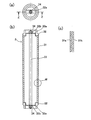
- FIG. 1 It is a schematic sectional drawing which shows the state at the time of filtration of 1st Embodiment of the filtration apparatus by this invention. It is a figure which shows the filter element of the filtration apparatus of FIG. 1, (a) is a top view, (b) is the ZZ sectional view taken on the line (a), (c) is the W section enlarged view of (b). . It is a conceptual diagram which shows the structural example of the innermost layer of the filter medium of the filter element by this invention, (a) shows the example comprised by the metal mesh of a plain weave, (b) punching metal, respectively.
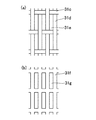
- FIG. 1 It is a conceptual diagram which shows the structural example of the innermost layer of the filter medium of the other filter element by this invention
- (a) is a top view which shows the example comprised by the plain woven wire mesh
- (b) is W- of (a). It is a W line sectional view.
- FIG. 10 is a sectional view taken along line DD of the filtration device of FIG. 9.
- FIG. 10 is a cross-sectional view of the filtration device of FIG. 9 taken along the line EE.
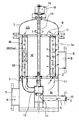
- FIG. 1 is a schematic cross-sectional view showing a state during filtration of the first embodiment of the filtration device according to the present invention.
- This filtration device filters the ballast water of a ship.
- the casing 1 forms an outer shell of the filtration device, and is formed in a bottomed and covered cylindrical shape (for example, a cylindrical shape) or a rectangular parallelepiped shape.
- a fluid inlet 7 through which fluid flows into the lower end portion of the side wall from the outside.
- a fluid outlet 8 for discharging the fluid filtered inside to the outside at the upper part of the side wall.
- the material of the casing 1 is metal, synthetic resin, or the like, and the shape and size of the casing 1 may be appropriately determined according to the purpose of use of the filtration device, the type and amount of liquid and gas to be passed, the installation location, and the like.
- a first partition wall 2 is horizontally provided at the lower part inside the casing 1.
- the first partition wall 2 includes a first stock solution chamber 9a that communicates with the fluid inlet 7 in the casing and accommodates a fluid before filtration, and a filtrate chamber that communicates with the fluid outlet 8 and accommodates a filtered fluid.
- 10 is a partition wall that is isolated from 10. Through holes 11 for fitting and holding one end (lower end) of the filter element are formed at the plurality of locations.
- a plurality of filter elements 3 are fitted and held in the through holes 11 on the upper side of the first partition wall 2.
- the first stock solution chamber 9a communicates with the first stock solution chamber 9a and is provided in the filtrate chamber 10 in parallel in the vertical direction.
- the filter element 3 passes the target fluid from the inside to the outside, captures and filters solids and gel-like dust contained in the fluid, and filters the fluid in the filter element in the axial direction. It is washed by flowing and formed into a cylindrical shape, for example, a cylindrical shape.
- the filter elements 3 are arranged on, for example, concentric circles.
- the filter element 3 has a cylindrical filter medium 31 having both ends opened, and a substantially annular end that fits and reinforces both ends.
- a central shaft 33 that is disposed on the central axis of the member 32 and the filter medium 31 and that has both end portions that are male screw portions inserted into a central hole 32b provided in the bridging portion 32a of each end member 32; And nuts 34 that are screwed into the male threaded portions at both ends of the central shaft 33 to fix the end members 32 on both sides so as not to fall off the filter medium 31.
- the filter medium 31 constitutes the main body portion of the filter element, and may be any material as long as it is stacked in a plurality of layers and the innermost layer 31a has the finest mesh. For example, there are those formed by sintering after being molded into a cylindrical shape, those made of a cylindrical notch wire, and those made of a wedge wire.
- the mesh size of the innermost layer 31a may be 10 to 200 ⁇ m, and the mesh size of the outer layer may be appropriately selected from 200 to 5000 ⁇ m.
- the reinforcing mesh 31b and the protective mesh 31b other than the innermost layer are related to the strength of the filter element, and the number of layers, the size of the mesh, and the wire diameter are selected so that the required strength can be obtained.
- plain weave, twill weave, satin weave, tatami weave, twill tatami weave and the like can be applied as the mesh weave.
- the innermost layer is a metal mesh, and a cylindrical punching tube having numerous square holes, for example, and a reinforcing member in which a plurality of thin rods are arranged along the axial direction are disposed on the outer side. You may tie it.
- the shape, size, number, and the like of the filter element 3 may be appropriately determined according to the purpose of use of the filtration device, the filtration performance, the size of the casing 1, the type of the target fluid, and the like.
- a structure without the shaft rod 33 or the like may be used.
- the axial flow inside the filter element 3 is used for cleaning the filter element 3, it is necessary not to provide a partition or a throttle that prevents the axial flow inside the filter element 3. .
- the width of the bridging portion 32a is made as small as possible to ensure a large opening area of the end member 32.
- the second partition 4 is provided horizontally in parallel with the first partition 2 on the other end (upper end) side of the filter element 3.
- the second partition wall 4 holds the upper end portion of the filter element 3 with a plurality of through-holes 12 and isolates the filtrate chamber 10 on the upper end side from other portions to provide a second stock solution chamber. It is a partition which forms 9b.
- the second stock solution chamber 9b is formed between the upper end lid of the casing 1 and the second partition wall 4.
- the second undiluted solution chamber 9b communicates with the first undiluted solution chamber 9a and contains a fluid before filtration.
- the communication with the first undiluted solution chamber 9a is performed using the inside of the tubular filter element 3 as a communication path.
- the communication with the cylindrical wall of the third and fourth embodiments described later is performed.
- a separate communication path may be provided like a path.
- a cleaning pipe 5 is disposed below the first partition wall 2.
- the cleaning pipe 5 extends in the radial direction from the base end portion 13 to the left, and is connected to the filter element 3 through a through hole 11 drilled in the first partition wall 2.
- FIG. 1 shows the case where the number of the cleaning pipes 5 is one, two or more cleaning pipes 5 may be provided and connected to two or more filter elements 3 at the same time.
- the cleaning pipe 5 sucks the fluid inside the filter element 3 and connects the cleaning pipe from the second stock solution chamber 9b connected to the other end of the filter element via the other end. An axial flow is generated toward the end, and the trapped substance attached to the inside is peeled off.
- so-called “backwashing” in which a fluid is flowed from the outside to the inside of the filter element in the opposite direction to that during filtration is not necessarily performed.
- the suction of the fluid by the cleaning pipe This is because the pressure on the side of the cleaning pipe is lower than the pressure inside the filter element 3, and the flow toward the cleaning pipe 5 is caused by the pressure difference. Is meant to occur.
- suction of fluid by the cleaning pipe in this specification means that “a flow toward the cleaning pipe occurs due to a pressure difference”.
- a shaft 14 is attached to the base end portion 13 of the cleaning pipe 5 on the central axis thereof so as to protrude outward from the casing 1, and a gear box 15 is provided at the end of the shaft 14. It is provided and is rotated by a motor 16. Therefore, when the motor 16 is driven to rotate, the shaft 14 rotates, and as shown in FIG. 2, the cleaning pipe 5 rotates, for example, clockwise, and a plurality of filter elements arranged, for example, circumferentially.
- the cleaning pipe 5 is sequentially connected to the opening at the lower end of 3.
- the cleaning fluid drain pipe 6 is fixed to the casing 1, and a bearing mechanism such as a bearing is provided at a connection portion between the base end portion 13 of the cleaning pipe 5 and the connection port portion 17 of the base end portion.
- a sealing mechanism is provided so as to intervene and support, and prevent the discharge from mixing with the unfiltered fluid. Therefore, by rotating the motor 16, the cleaning pipe 5 is rotated while maintaining the seal between the base end portion 13 of the cleaning pipe 5 and the connection port portion 17 with the connection port portion 17 as a rotation support portion. To do.
- the fluid passes through the filter element due to a differential pressure between the pressure of the fluid in the stock solution chambers 9a and 9b (primary pressure P 1 ) and the pressure of the fluid in the filtrate chamber 10 (secondary pressure P 2 ). Filtered.
- the filter device is cleaned, in the filter element connected to the cleaning pipe, the difference between the pressure in the stock solution chambers 9a and 9b (primary pressure P 1 ) and the pressure on the discharge side of the on-off valve (P 0 ).
- the pressure (P 1 -P 0 ) generates and cleans the axial flow inside the filter element.
- a filter for filtering a large flow rate (for example, a ballast water filter) is designed so that the pressure loss in the transmission direction of the filter is small, and the value of P 1 -P 2 is about 0.05 MPa to 0.5 MPa. It is said that.
- the relationship between pressure levels is P 1 ⁇ P 1A , P 1B ⁇ P 0A , P 1A ⁇ P 2 , P 1B ⁇ P 2
- the pressure (P 1A , P 1B ) inside the filter element may be higher or lower than the pressure (P 2 ) in the outer filtrate chamber. That is, in the filtration device of the present invention, since one end of the filter element being cleaned is open to the stock solution chambers 9a and 9b, the pressure inside the filter element (P 1B or P 1A ) is the pressure of the stock solution chambers 9a and 9b. Since it becomes close to P 1 and the internal / external pressure difference (P 2 ⁇ P 1B or P 2 ⁇ P 1A ) of the filter element is small or negative, it is possible to prevent the adverse effects caused by the backwashing.
- FIG. 1 (during filtration) and FIG. 5 (during washing).
- the opening / closing valve of the cleaning fluid discharge system is closed, and as shown in FIG. 1, suction by the cleaning pipe 5 is not performed, and the cleaning pipe 5 is not rotated but is stationary.
- the fluid to be filtered flows from the fluid inlet 7 into the first stock solution chamber 9a of the housing 1 as indicated by the arrow A.
- the opening / closing valve of the cleaning fluid discharge system is opened, and suction by the cleaning pipe 5 is started and the cleaning pipe 5 is rotated by a motor 16 as shown in FIG.
- the fluid Since the inside of the filter element 3b to which the cleaning pipe 5 is connected is sucked by the cleaning pipe 5 to reduce the pressure, the fluid is filtered from the second stock solution chamber 9b having the primary pressure. It passes through the inside of 3b at high speed in the axial direction and flows out to the cleaning pipe 5. At this time, the trapped substance trapped inside the filter element 3b at the time of filtration is removed by this high-speed axial flow, and is discharged through the cleaning pipe 5 and the cleaning fluid drain pipe 6 together with the cleaning fluid. On the other hand, at this time, the fluid flows into the filter element 3a to which the cleaning pipe 5 is not connected, from the first stock solution chamber 9a as in the filtration, and the filtration is continued.
- the cleaning pipe 5 is rotated and sequentially connected to each filter element 3 and performs cleaning in the same manner as the filter element 3b. All filter elements 3 are cleaned by rotating a predetermined number of times at a predetermined rotation speed.
- the pores of the mesh for allowing the fluid of the filter medium 31 to pass through (that is, the innermost layer 31a) is parallel to the axis of the filter medium. It is configured to be a hole.
- the particles and the fibrous foreign matter caught in the mesh are axially flowed by the axial flow during the cleaning of the filtration device of the present invention. Easy to move in direction and easy to remove.
- FIG. 3A and 3B show structural examples of the innermost layer 31a of the filter medium having such long hole openings.
- FIG. 3A shows a long hole 31e in a filter medium made of a plain weave wire mesh by making the interval in the axial direction of the filter media of the wire meshes 31c and 31d longer than the interval in the circumferential direction.
- the innermost layer of the filter medium is a punching metal 31f, and a long hole 31g parallel to the axis of the filter medium is formed.
- any structure other than these can be used.
- the dimensional ratio of the long hole in the long axis direction / short axis direction is preferably 2 or more, and more preferably 3 or more.
- a coarser mesh 31b for reinforcement may be laminated on the outside of the innermost layer 31a having these configurations as described above.
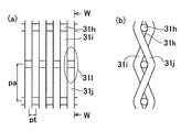
- the axial pitch pa of the filter medium of the filter medium (that is, the innermost layer 31a) for passing the fluid through and filtering is selected by the filter medium.
- the mesh is larger than the circumferential pitch pt of the filter medium.
- FIG. 4A shows an innermost layer 31a of a filter medium made of a plain woven mesh.
- the mesh extends in the circumferential direction of the filter medium and extends in a direction parallel to the axis of the filter medium and a plurality of vertical lines 31h (lateral direction in the figure) arranged at intervals with a large pitch pa in the axial direction.
- a plurality of horizontal lines 31i and 31j (longitudinal direction in the figure) closely arranged with a small pitch pt in the direction are formed by tatami weaving.
- the adjacent horizontal lines 31i and 31j are woven so as to wrap around from the different sides of each vertical line 31h, so that a gap 31k is formed between the horizontal lines 31i and 31j and the vertical line 31h. (See cross-sectional view 4b), and the fluid is filtered by passing therethrough.
- the groove portion 31l is formed between every other horizontal line 31i, 31i or 31j, 31j, foreign matter such as particles or fibers may be caught in the groove portion 31l.
- the direction of the horizontal lines 31i, 31j is parallel to the axis of the filter medium (the axis of the filter element), so the direction of the groove 31l is also the axis direction of the filter element, and is used in the filtration device of the present invention. Due to the axial flow during the cleaning, foreign matters such as particles and fibers caught in the groove 31l are easily moved in the axial direction and are easily removed.
- the structure of the innermost layer 31a in which the axial pitch pa of the filter medium mesh is larger than the circumferential pitch pt of the filter medium mesh may be any structure other than the above.
- the same effect can be obtained even when a twill woven mesh is used.
- the use of the filter element shown in FIGS. 3 and 4 is effective in achieving the effect of the present invention of cleaning the filter element by the axial flow.
- the filter device of the present invention can achieve the above-described effect even if a conventional filter element is used, not limited to those shown in FIGS.
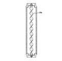
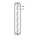
- the turbulent flow generating member 35 is formed as an abacus-shaped protrusion 35 a provided on the central shaft rod 33 at a constant interval.
- a ribbon-shaped plate 35b is twisted as shown in FIG. 7, and a wire 35c is spirally wound around the central shaft rod 33 as shown in FIG.
- the turbulent flow generation member 35 is not limited to these examples, and any member may be used as long as it can generate turbulent flow.
- a filter that generates turbulent flow over the entire length of the filter element and that does not excessively prevent axial flow is preferable.
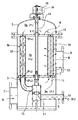
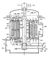
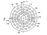
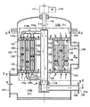
- FIG. 9 is a schematic cross-sectional view showing a state of the filtration device of this embodiment during cleaning
- FIG. 10 is a cross-sectional view taken along the line DD
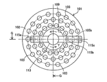
- FIG. 11 is a cross-sectional view taken along the line EE. 9 corresponds to a cross-sectional view taken along line FF in FIG.
- This filtering device also filters ship ballast water and the like, and includes a casing 101, a first partition wall 102, a filter element 103, a second partition wall 104, cleaning pipes 105a and 105b, and a cleaning fluid drain. And a pipe 106.
- donut plate-like mounting plates (first and second partition walls) 102 and 104 having a circular opening at the center are attached to the lower and upper parts, and the mounting plates 102 and 104.
- a cylindrical wall 109 is provided up and down on the periphery of the central opening. Through holes 110 are formed at a plurality of locations of the mounting plates 102 and 104. In this state, a donut-shaped cylindrical space surrounded by the inner wall of the casing 1, the mounting plates 102 and 104 and the cylindrical wall 109 is formed.
- a plurality of filter elements 103 are provided in parallel in a donut cylindrical space surrounded by the inner wall of the casing 101, the mounting plates 102 and 104, and the cylindrical wall 109.
- This filter element 103 passes the target fluid from the inside to the outside and filters the fluid, and is the same as the filter element 3 of the first embodiment shown in FIG.
- Each filter element 103 is open at both ends in the longitudinal direction, and the openings at both ends are coupled to through holes 110 drilled in the mounting plates 102 and 104, respectively, and are arranged vertically in the casing 101. Has been.
- the donut-shaped cylindrical space surrounded by the inner wall of the casing 1, the mounting plates 102 and 104, and the cylindrical wall 109 becomes a filtrate chamber 111 in which the filtered fluid is accommodated.
- the space below the mounting plate 102, the upper side of the mounting plate 104, and the space inside the cylindrical wall 109 all contain the fluid before filtration.
- the portion is called the first stock solution chamber 112a
- the upper portion of the mounting plate 4 is called the second stock solution chamber 112b
- the inside of the cylindrical wall 109 is the communication passage 112c.
- the plurality of filter elements 103 communicate with the first stock solution chamber 112a and the second stock solution chamber 112b in the filtrate chamber 111, for example, in three rows concentrically. They are arranged side by side.
- the cleaning nozzle 114 of the first cleaning pipe 105 a is connected to the opening at the upper end of some of the plurality of filter elements 103, and the opening at the lower end of the other part of the filter elements 103. Is connected to the cleaning nozzle 115 of the second cleaning pipe 105b. These cleaning pipes 105a and 105b suck the fluid inside the filter element 103, and connect the cleaning pipe from the stock solution chamber connected to the opposite end of the filter element via the end. An axial flow is generated toward the end, and the trapped substance attached to the inside is peeled off.
- the first cleaning pipe 105a extends in the radial direction from the upper end of the hollow discharge pipe 113 rotatably provided at the center of the casing 101, and the cleaning nozzles 114b and 114c are the center. Are connected to the upper end portions of the filter elements 103 in the first row and the third row from the through holes 110.
- FIG. 9 corresponds to the cross-sectional view taken along the line FF of FIG. 10, it is not shown in FIG. 9, but the first cleaning pipe 105a actually extends to the right side as shown in FIG.
- the cleaning nozzle 114 a is connected to the upper end of the filter element 103 in the second row from the center via the through hole 110.
- FIG. 9 corresponds to the sectional view taken along the line GG of FIG. 11 and is not shown in FIG. 9, but the second cleaning pipe 105b actually extends to the right side as shown in FIG.
- the cleaning nozzles 115 b and 115 c are connected to the lower end portions of the filter elements 103 in the first and third rows from the center portion through the through holes 110.
- the first cleaning pipe 105a and the second cleaning pipe 105b are rotationally driven by a motor 118 through a shaft 116 and a gear box 117 together with a discharge pipe 113.
- the first and second cleaning pipes 105a and 10b rotate in the arrow X direction (Y direction in FIG. 11), and correspond to the respective concentric circles at the upper ends of the plurality of filter elements 103 arranged concentrically.
- the cleaning nozzles 114a, 114b, 114c of the first cleaning pipe 105a are sequentially connected.
- the cleaning nozzles 115a, 115b, and 115c of the second cleaning pipe 105b corresponding to the respective concentric circles are sequentially connected to the lower ends of the filter elements 103.
- the cleaning nozzles 114a, 114b, and 114c of the first cleaning pipe 105a are arranged at positions shifted by 180 degrees with respect to the cleaning nozzles 115a, 115b, and 115c of the second cleaning pipe 105b. Therefore, by rotating the first cleaning pipe 105a and the second cleaning pipe 105b, the both ends (upper end and lower end) of each filter element 103 are cleaned on the first cleaning pipe 105a side.
- the nozzle 114 and the cleaning nozzle 115 on the second cleaning pipe 105b side are connected with a 180 ° timing shift.
- the arrangement angle between the first cleaning pipe 105a and the second cleaning pipe 105b is not limited to 180 degrees, and may be any number other than 0 degrees, for example, 90 degrees. That is, the cleaning nozzles of the first and second cleaning pipes 105a and 105b may not be connected to both ends of the same filter element at the same time.
- the cleaning fluid drain pipe 6 is released to atmospheric pressure (P 0 ) via an open / close valve (not shown).
- the operation (use state) of the thus configured filtration device will be described with reference to FIGS.
- the rotation of the cleaning pipe stops, and the opening / closing valve (not shown) connected to the cleaning fluid drain pipe 6 is closed, so that the fluid of the cleaning pipes 5a and 5b Suction is also stopped.
- the target fluid flows from the fluid inlet 7 as indicated by an arrow C, and from openings at both ends (upper and lower ends) of the filter element 103 provided in parallel between the lower and upper mounting plates 2 and 4. Inflow.
- the filter element not connected to the cleaning pipes 105a and 105b Flows into the inside from both ends of the filter element and is filtered by passing through the filter medium from the inside to the outside.
- the filter element connected to the cleaning pipes 105a and 105b the fluid flows into the inside from the end of the filter element that is not connected to the cleaning pipe, and also passes through the filter medium from the inside to the outside. Is filtered.
- the fluid filtered through the filter element 103 flows out from the fluid outlet 108 as indicated by an arrow B.
- the cleaning pipes 105a and 105b rotate as shown in FIG. 9, and the valve (not shown) connected to the cleaning fluid drain pipe 106 is released, so that the cleaning pipes 105a and 105b Fluid is aspirated. Therefore, in the filter element 103 connected to the cleaning nozzles 114b and 114c of the upper cleaning pipe 105a, fluid flows in from the first stock solution chamber 112a on the other end (lower side) in the filter element in the axial direction. Flow and sucked into the cleaning pipe 105a. In the filter element 103 connected to the cleaning nozzle 115a of the lower cleaning pipe 105b, fluid flows from the second stock solution chamber 112b at the other end (upper side) and flows in the filter element in the axial direction.
- the upper cleaning pipe 5a is rotated clockwise (X direction) when viewed from above by a motor 118 as shown in FIG. 10, and each filter element has one of the cleaning nozzles 114a to 114c during one rotation. Are connected one by one from above and washed with an axial flow from below to above.
- the lower cleaning pipe 105b rotates counterclockwise (Y direction) when viewed from below, and each filter element has one of the cleaning nozzles 115a to 115c during one rotation. Are connected one by one from above and washed with an axial flow from top to bottom.
- each filter element is cleaned once by the axial flow from the bottom to the top while the cleaning pipes 105a and 105b rotate once. Washing with a downward axial flow is performed once. Cleaning is performed by rotating the cleaning pipes 105a and 105b a predetermined number of times.
- the fluid flows into the inside from the ends on both sides of the filter element as in normal filtration. And filtration is performed by passing from the inside to the outside.
- FIG. 12 is a schematic cross-sectional view showing this embodiment of the filtration device, and shows a state during cleaning.
- This filtration apparatus is an improvement of the apparatus of the third embodiment, and the only difference from the third embodiment is that a trapped material removal tool 135 is provided inside each filter element 103. Accordingly, the same components as those in the third embodiment shown in FIGS. 9 to 11 are denoted by the same reference numerals, and the description thereof is omitted.
- FIG. 13 shows the structure of the filter element 103 of this filtration device.
- FIG. 13 is a longitudinal sectional view showing a state of the filter element 103 during filtration, and shows the attachment plates 102 and 104 to be connected and the adjacent filter elements.
- the structure of the filter element 103 is the same as that of the filter element 3 or 103 of the first or third embodiment except that the filter element 103 has the trapping object removing tool 135 and the like.
- the pores of the mesh of the filter medium are long holes parallel to the axis of the filter medium, because foreign matter caught in the mesh can be easily removed by the trapping material removing tool 135.
- the axial pitch of the filter media in the mesh of the filter media is larger than the circumferential pitch of the filter media in the filter media because foreign matter caught in the mesh can be easily removed by the captured material removing tool 135.
- the trapping material removing tool 135 moves in the axial direction in the filter element 103 due to an axial fluid flow generated during filtration or washing, and the outer peripheral portion is slidably in contact with the inner peripheral surface of the filter element 103. This removes an object and is configured as a removal brush as shown in FIG.
- the removal brush 135 moves up and down along the central axis bar 133 inside the filter element 103, and is formed by planting brush bristles 135b on the outer periphery of the brush body 135a.
- the brush body 135a is formed with a hole into which the central shaft 133 is fitted at the center, and the outer diameter is smaller than the inner diameter of the filter element 103, and is formed in a donut shape having a predetermined thickness.
- On the outer peripheral portion of the brush main body 135a brush hairs 135b whose hair tips can be brought into sliding contact with the inner peripheral surface of the filter element 103 are planted in a ring shape.
- the length of the bristles of the bristles 135b needs to be at least such that the tips of the bristles 135b come into contact with the inner peripheral surface of the filter element 103 with a certain amount of pressure.
- the material of the brush bristles 135b may be anything as long as it is generally used as brush bristles such as natural or synthetic fibers, or metal wires such as steel, copper, and brass.
- the brush bristles 135b are flexible enough to bend by the pressure of the fluid flowing in the filter element 103. As a result, when the bristles 135b are bent by the pressure of the fluid, a gap is formed between the inner peripheral surface of the filter element 103 and the bristles of the brush bristles 135b, so that the fluid can flow.
- stoppers 136 are attached to the upper end portion and the lower end portion of the central shaft rod 133 in the filter element 103.
- the stopper 136 stops the removal brush 135 at the upper and lower end portions when the removal brush 135 moves up and down along the central axis bar 133 inside the filter element 103.
- the material of the stopper 136 is more preferably a material that can absorb an impact, such as rubber or a spring.
- FIGS. 14 and 15 are longitudinal sectional views showing the state of the filter element 103 during cleaning, together with the attachment plates 102 and 104 and the adjacent filter elements that are connected in the same manner as in FIG. 13, and also the cleaning nozzle.
- the filter element 103 is in the third row from the center, and the cleaning nozzles 114c and 115c are connected.
- the filter elements in the other rows are also connected to the corresponding cleaning nozzles, and the same operation is performed. .
- FIG. 13 shows that when the filtering device performs the filtering operation as described above, or performs the cleaning operation, the first and second cleaning elements are opened at the upper and lower openings of the filter element 103.
- the cleaning nozzles 114c and 115c of the pipes 105a and 105b are not applied, and the filter element 103 shows a state where fluid is being filtered. In this state, fluid flows from the first stock solution chamber 112a and the second stock solution chamber 112b into the filter element 103 through the openings at the upper and lower ends of the filter element 103, and from the inside toward the outside. The fluid passes through and is filtered.
- the removal brush 135 provided in the filter element 103 is pushed by the unfiltered fluid flowing in from the opening at the upper end and the lower end, and the position where the flow pressure in the filter element 103 balances, for example, Stopped in the middle part.
- FIG. 14 shows that the first and second cleaning pipes 105a and 105b are rotated in the direction indicated by the arrow X in FIG. 10 (the direction indicated by the arrow Y in FIG. 11) from the state shown in FIG.
- the cleaning nozzle 114c of the first cleaning pipe 5a is applied to the opening, and the cleaning is being performed.
- an axial flow from the first stock solution chamber 112a connected to the lower end portion of the filter element 103 to the upper end portion of the opening via the lower end portion is formed by suction by the cleaning nozzle 114c. ing.
- the removal brush 135 in the filter element 103 is pushed upward along the central shaft rod 133, and the brush bristles 135 b on the outer peripheral portion thereof are in sliding contact with the inner peripheral surface of the filter element 103. Then, the trapped substance adhering to the surface is removed while being pushed up to the uppermost position and hits the stopper 136 at the upper end to stop.
- the removal brush 135 that has stopped by hitting the stopper 136 has its bristle 135b bent by the action of the axial flow, and a gap is formed between the inner peripheral surface of the filter element 103, and the cleaning fluid is washed from the opening at the upper end. It flows to the nozzle 114c.
- the trapped substance removed from the inner peripheral surface of the filter element 103 by the movement of the removal brush 135 and the axial flow flows to the first cleaning pipe 105a via the cleaning nozzle 114c, and the discharge pipe shown in FIG. 113 is sent to the cleaning fluid drain pipe 106 and discharged to the outside.
- the first and second cleaning pipes 105 a and 105 b further rotate and the cleaning nozzle 115 c of the second cleaning pipe 105 b is applied to the opening at the lower end of the filter element 103, and cleaning is performed.
- It shows the state. In this state, an axial flow from the second stock solution chamber 112b connected to the upper end portion of the filter element 103 to the lower end opening through the upper end opening is formed by suction by the cleaning nozzle 115c. ing. Due to this upward axial flow, the removal brush 135 in the filter element 103 is pushed down along the central shaft rod 133, and the brush bristles 135 b on the outer peripheral portion thereof are in sliding contact with the inner peripheral surface of the filter element 103. Then, it is pushed down to the lowest position while removing the trapped substance adhering to the surface, and hits the stopper 136 at the lower end to stop.
- the removal brush 135 that has stopped by hitting the stopper 136 has its bristle 135b bent by the action of the axial flow, so that a gap is formed between the inner surface of the filter element 103 and the cleaning fluid is washed from the opening at the lower end. It flows to the nozzle 115c.
- the trapped material removed from the inner peripheral surface of the filter element 103 by the movement of the removal brush 135 and the axial flow shown in FIG. 15 flows to the second cleaning pipe 105b via the cleaning nozzle 115c. Thereafter, the removed trapped material and the cleaning fluid are sent to the cleaning fluid drain pipe 106 through the discharge pipe 113 shown in FIG. 12 and discharged to the outside.
- the filter element 103 performs cleaning by repeating the upward and downward axial flows shown in FIGS. 13 to 15 and the reciprocating operation of the removal brush 135 thereby.
- the cleaning pipes 105a and 105b are rotated by the motor 118 during cleaning and are sequentially connected to all the filter elements, so that all the filter elements are cleaned.
- the operation during filtration is the same as in the first to third embodiments.
- the filter device having the plurality of filter elements 3 and 103 is shown.
- the filter device of the present invention may have one filter element.
- a cleaning pipe integrated with a non-rotating cleaning fluid drain pipe is provided to always connect to one end of the filter element, and fluid is supplied from the other end of the filter element during filtration. Then, it is filtered by passing from the inside to the outside, and at the time of cleaning, the fluid is sucked from the one end by the cleaning pipe, and the axial flow from the other end to the one end is generated for cleaning. good.
- the filter element 3 or 103 may be filtered or backwashed inside. If it moves in the axial direction according to the flow of the fluid and the members on the outer peripheral portion can slide on the inner peripheral surface of the filter elements 3 and 103 to remove the captured matter, for example, a blade shape or a spatula shape It may be a metal, resin or rubber scraper formed in the above.
- Fluid inlet 108 ... Fluid outlet 109 ... Cylindrical wall 110 ... Through hole 111 . Filtrate chamber 112a ... First concentrate chamber 112b ; Second concentrate chamber 113c ... Communication path 135 ... Capture removal tool (removal brush) pa ... Axial pitch of mesh pt ... Pitch in circumferential direction of mesh
Landscapes
- Chemical & Material Sciences (AREA)
- Chemical Kinetics & Catalysis (AREA)
- Filtration Of Liquid (AREA)
- Filtering Materials (AREA)
- Filtering Of Dispersed Particles In Gases (AREA)
Priority Applications (4)
| Application Number | Priority Date | Filing Date | Title |
|---|---|---|---|
| KR1020167006185A KR102388303B1 (ko) | 2014-06-30 | 2015-03-25 | 여과 장치 및 필터 엘리먼트 |
| DE112015003072.7T DE112015003072B4 (de) | 2014-06-30 | 2015-03-25 | Filtervorrichtung und Filterelement |
| CN201580001829.6A CN105531007B (zh) | 2014-06-30 | 2015-03-25 | 过滤装置和滤芯 |
| US15/028,413 US10052574B2 (en) | 2014-06-30 | 2015-03-25 | Filtration device and filter element |
Applications Claiming Priority (2)
| Application Number | Priority Date | Filing Date | Title |
|---|---|---|---|
| JP2014-134510 | 2014-06-30 | ||
| JP2014134510A JP6309370B2 (ja) | 2014-06-30 | 2014-06-30 | 濾過装置及びフィルターエレメント |
Publications (1)
| Publication Number | Publication Date |
|---|---|
| WO2016002275A1 true WO2016002275A1 (ja) | 2016-01-07 |
Family
ID=55018834
Family Applications (1)
| Application Number | Title | Priority Date | Filing Date |
|---|---|---|---|
| PCT/JP2015/059170 Ceased WO2016002275A1 (ja) | 2014-06-30 | 2015-03-25 | 濾過装置及びフィルターエレメント |
Country Status (6)
| Country | Link |
|---|---|
| US (1) | US10052574B2 (enExample) |
| JP (1) | JP6309370B2 (enExample) |
| KR (1) | KR102388303B1 (enExample) |
| CN (1) | CN105531007B (enExample) |
| DE (1) | DE112015003072B4 (enExample) |
| WO (1) | WO2016002275A1 (enExample) |
Cited By (1)
| Publication number | Priority date | Publication date | Assignee | Title |
|---|---|---|---|---|
| CN113975869A (zh) * | 2021-10-15 | 2022-01-28 | 新疆农业科学院吐鲁番农业科学研究所(吐鲁番市农业科学研究院) | 果酒发酵后过滤装置 |
Families Citing this family (17)
| Publication number | Priority date | Publication date | Assignee | Title |
|---|---|---|---|---|
| CN102712018B (zh) * | 2009-11-12 | 2015-10-07 | 过滤器安全有限公司 | 过滤器近端喷嘴 |
| JP6059283B2 (ja) | 2015-04-20 | 2017-01-11 | 富士フィルター工業株式会社 | 濾過ユニット |
| DE102017001970A1 (de) * | 2016-10-12 | 2018-04-12 | Hydac Process Technology Gmbh | Filtervorrichtung |
| CN106430371B (zh) * | 2016-12-09 | 2023-05-12 | 中冶赛迪工程技术股份有限公司 | 过滤装置和高炉冲渣水过滤器 |
| CN107051123B (zh) * | 2017-01-04 | 2023-09-26 | 重庆启甲科技有限公司 | 一种滤芯与支承板的安装结构 |
| DE102017004661A1 (de) * | 2017-05-08 | 2018-11-08 | Hydac Process Technology Gmbh | Filtervorrichtung |
| CN107349717A (zh) * | 2017-09-01 | 2017-11-17 | 苏州百硕自动化环保设备有限公司 | 一种气体除尘净化装置 |
| CN107376503B (zh) * | 2017-09-14 | 2019-09-03 | 成都康辉生物科技有限公司 | 用于植物提取液的固液分离机 |
| CN109200658B (zh) * | 2018-11-16 | 2021-11-30 | 蚌埠碧水蓝环境科技有限公司 | 一种污水过滤装置 |
| JP7397463B2 (ja) * | 2019-07-31 | 2023-12-13 | 富士フィルター工業株式会社 | 濾過装置及びそのフィルタ洗浄方法 |
| RU2716784C1 (ru) * | 2019-11-26 | 2020-03-16 | Евгений Михайлович Булыжёв | Устройство фильтрования больших объемов воды |
| TW202537016A (zh) * | 2020-01-06 | 2025-09-16 | 荷蘭商Asm Ip私人控股有限公司 | 過濾板 |
| CN111686490A (zh) * | 2020-06-23 | 2020-09-22 | 夏春辉 | 一种自洁式磨板机用铜粉回收装置 |
| CN112707549B (zh) * | 2021-01-29 | 2022-03-11 | 北部湾大学 | 一种化学实验用废水处理装置 |
| CN112957829B (zh) * | 2021-02-04 | 2022-05-06 | 郑州大学第一附属医院 | 一种用于呼吸机的过滤装置 |
| US12605650B2 (en) * | 2021-02-26 | 2026-04-21 | Shounan Engineering Inc. | Method for removing oil in cleaning liquid |
| CN113209692B (zh) * | 2021-05-24 | 2022-10-21 | 青海中煤地质工程有限责任公司 | 一种地热尾水回灌用自动反冲洗预过滤装置 |
Citations (9)
| Publication number | Priority date | Publication date | Assignee | Title |
|---|---|---|---|---|
| US2858894A (en) * | 1954-06-14 | 1958-11-04 | Swan M Akeyson | Screen pipe |
| US3380591A (en) * | 1965-06-11 | 1968-04-30 | Rellumit Inter S A R L | Fluid filter with automatic cleaning device |
| JPH0268380A (ja) * | 1988-09-02 | 1990-03-07 | Aikawa Tekko Kk | 製紙用スクリーン |
| JPH0338119U (enExample) * | 1989-08-21 | 1991-04-12 | ||
| JPH05212216A (ja) * | 1992-02-07 | 1993-08-24 | Reika Kogyo Kk | 濾過装置 |
| US20120125834A1 (en) * | 2009-07-02 | 2012-05-24 | Christian Gessner | Filter device and filter element arrangement for use in the filter device |
| JP2013013839A (ja) * | 2011-07-01 | 2013-01-24 | Jfe Engineering Corp | 濾過装置 |
| WO2013029761A1 (de) * | 2011-08-30 | 2013-03-07 | Hydac Process Technology Gmbh | Filtervorrichtung |
| JP2014034029A (ja) * | 2012-08-10 | 2014-02-24 | Fuji Filter Kogyo Kk | 濾過装置 |
Family Cites Families (6)
| Publication number | Priority date | Publication date | Assignee | Title |
|---|---|---|---|---|
| JPH0338119A (ja) | 1989-07-05 | 1991-02-19 | Fujitsu Ltd | 自動等化器 |
| DE4345412C2 (de) * | 1993-11-26 | 1999-11-11 | Boll & Kirch Filter | Filterkerze |
| FI110483B (fi) | 1999-09-20 | 2003-02-14 | Parker Hannifin Oy | Suodatuslaitteisto |
| WO2007062763A1 (de) | 2005-12-01 | 2007-06-07 | Boll & Kirch Filterbau Gmbh | Rückspülfilter und filterelement hierfür |
| JP5916537B2 (ja) * | 2012-06-27 | 2016-05-11 | Jfeエンジニアリング株式会社 | 濾過体、これを有する濾過装置及び海水処理装置 |
| DE112014006168B4 (de) | 2014-01-15 | 2025-08-07 | Fuji Filter Manufacturing Co., Ltd. | Filterelement und Filtervorrichtung |
-
2014
- 2014-06-30 JP JP2014134510A patent/JP6309370B2/ja active Active
-
2015
- 2015-03-25 KR KR1020167006185A patent/KR102388303B1/ko active Active
- 2015-03-25 US US15/028,413 patent/US10052574B2/en active Active
- 2015-03-25 WO PCT/JP2015/059170 patent/WO2016002275A1/ja not_active Ceased
- 2015-03-25 CN CN201580001829.6A patent/CN105531007B/zh active Active
- 2015-03-25 DE DE112015003072.7T patent/DE112015003072B4/de active Active
Patent Citations (9)
| Publication number | Priority date | Publication date | Assignee | Title |
|---|---|---|---|---|
| US2858894A (en) * | 1954-06-14 | 1958-11-04 | Swan M Akeyson | Screen pipe |
| US3380591A (en) * | 1965-06-11 | 1968-04-30 | Rellumit Inter S A R L | Fluid filter with automatic cleaning device |
| JPH0268380A (ja) * | 1988-09-02 | 1990-03-07 | Aikawa Tekko Kk | 製紙用スクリーン |
| JPH0338119U (enExample) * | 1989-08-21 | 1991-04-12 | ||
| JPH05212216A (ja) * | 1992-02-07 | 1993-08-24 | Reika Kogyo Kk | 濾過装置 |
| US20120125834A1 (en) * | 2009-07-02 | 2012-05-24 | Christian Gessner | Filter device and filter element arrangement for use in the filter device |
| JP2013013839A (ja) * | 2011-07-01 | 2013-01-24 | Jfe Engineering Corp | 濾過装置 |
| WO2013029761A1 (de) * | 2011-08-30 | 2013-03-07 | Hydac Process Technology Gmbh | Filtervorrichtung |
| JP2014034029A (ja) * | 2012-08-10 | 2014-02-24 | Fuji Filter Kogyo Kk | 濾過装置 |
Cited By (1)
| Publication number | Priority date | Publication date | Assignee | Title |
|---|---|---|---|---|
| CN113975869A (zh) * | 2021-10-15 | 2022-01-28 | 新疆农业科学院吐鲁番农业科学研究所(吐鲁番市农业科学研究院) | 果酒发酵后过滤装置 |
Also Published As
| Publication number | Publication date |
|---|---|
| KR20170021763A (ko) | 2017-02-28 |
| DE112015003072B4 (de) | 2023-10-26 |
| DE112015003072T5 (de) | 2017-03-23 |
| JP2016010788A (ja) | 2016-01-21 |
| CN105531007B (zh) | 2019-08-09 |
| US10052574B2 (en) | 2018-08-21 |
| US20160228801A1 (en) | 2016-08-11 |
| JP6309370B2 (ja) | 2018-04-11 |
| CN105531007A (zh) | 2016-04-27 |
| KR102388303B1 (ko) | 2022-04-19 |
Similar Documents
| Publication | Publication Date | Title |
|---|---|---|
| JP6309370B2 (ja) | 濾過装置及びフィルターエレメント | |
| JP2016010788A5 (enExample) | ||
| JP6076647B2 (ja) | 濾過装置 | |
| KR102156816B1 (ko) | 여과 장치 | |
| JP6262257B2 (ja) | フィルターエレメント及び濾過装置 | |
| US12036488B2 (en) | Method for operating filtration device | |
| JP6373711B2 (ja) | 濾過装置 | |
| JP6158581B2 (ja) | 濾過装置 | |
| JP6343231B2 (ja) | 濾過装置 | |
| JP2016073904A5 (enExample) | ||
| JP5759336B2 (ja) | 濾過装置 | |
| JP2017502841A (ja) | 流体濾過デバイスのための流通制御構造ならびに方法 | |
| KR101820959B1 (ko) | 실시간 세척기능을 가진 필터시스템 | |
| JP6608631B2 (ja) | 濾過装置及び濾過装置のフィルター洗浄方法 | |
| JP6928635B2 (ja) | 濾過装置及び濾過装置のフィルター洗浄方法 | |
| KR20190022261A (ko) | 실시간 세척기능을 가진 필터시스템 |
Legal Events
| Date | Code | Title | Description |
|---|---|---|---|
| WWE | Wipo information: entry into national phase |
Ref document number: 201580001829.6 Country of ref document: CN |
|
| 121 | Ep: the epo has been informed by wipo that ep was designated in this application |
Ref document number: 15814961 Country of ref document: EP Kind code of ref document: A1 |
|
| ENP | Entry into the national phase |
Ref document number: 20167006185 Country of ref document: KR Kind code of ref document: A |
|
| WWE | Wipo information: entry into national phase |
Ref document number: 15028413 Country of ref document: US |
|
| WWE | Wipo information: entry into national phase |
Ref document number: 112015003072 Country of ref document: DE |
|
| 122 | Ep: pct application non-entry in european phase |
Ref document number: 15814961 Country of ref document: EP Kind code of ref document: A1 |