WO2015194468A1 - 粒子状物質検出装置 - Google Patents
粒子状物質検出装置 Download PDFInfo
- Publication number
- WO2015194468A1 WO2015194468A1 PCT/JP2015/066978 JP2015066978W WO2015194468A1 WO 2015194468 A1 WO2015194468 A1 WO 2015194468A1 JP 2015066978 W JP2015066978 W JP 2015066978W WO 2015194468 A1 WO2015194468 A1 WO 2015194468A1
- Authority
- WO
- WIPO (PCT)
- Prior art keywords
- particulate matter
- temperature
- heating
- exhaust gas
- detection means
- Prior art date
- Legal status (The legal status is an assumption and is not a legal conclusion. Google has not performed a legal analysis and makes no representation as to the accuracy of the status listed.)
- Ceased
Links
Images
Classifications
-
- F—MECHANICAL ENGINEERING; LIGHTING; HEATING; WEAPONS; BLASTING
- F01—MACHINES OR ENGINES IN GENERAL; ENGINE PLANTS IN GENERAL; STEAM ENGINES
- F01N—GAS-FLOW SILENCERS OR EXHAUST APPARATUS FOR MACHINES OR ENGINES IN GENERAL; GAS-FLOW SILENCERS OR EXHAUST APPARATUS FOR INTERNAL-COMBUSTION ENGINES
- F01N11/00—Monitoring or diagnostic devices for exhaust-gas treatment apparatus
- F01N11/002—Monitoring or diagnostic devices for exhaust-gas treatment apparatus the diagnostic devices measuring or estimating temperature or pressure in, or downstream of the exhaust apparatus
-
- F—MECHANICAL ENGINEERING; LIGHTING; HEATING; WEAPONS; BLASTING
- F01—MACHINES OR ENGINES IN GENERAL; ENGINE PLANTS IN GENERAL; STEAM ENGINES
- F01N—GAS-FLOW SILENCERS OR EXHAUST APPARATUS FOR MACHINES OR ENGINES IN GENERAL; GAS-FLOW SILENCERS OR EXHAUST APPARATUS FOR INTERNAL-COMBUSTION ENGINES
- F01N3/00—Exhaust or silencing apparatus having means for purifying, rendering innocuous, or otherwise treating exhaust
- F01N3/02—Exhaust or silencing apparatus having means for purifying, rendering innocuous, or otherwise treating exhaust for cooling, or for removing solid constituents of, exhaust
- F01N3/021—Exhaust or silencing apparatus having means for purifying, rendering innocuous, or otherwise treating exhaust for cooling, or for removing solid constituents of, exhaust by means of filters
-
- F—MECHANICAL ENGINEERING; LIGHTING; HEATING; WEAPONS; BLASTING
- F02—COMBUSTION ENGINES; HOT-GAS OR COMBUSTION-PRODUCT ENGINE PLANTS
- F02D—CONTROLLING COMBUSTION ENGINES
- F02D41/00—Electrical control of supply of combustible mixture or its constituents
- F02D41/02—Circuit arrangements for generating control signals
- F02D41/04—Introducing corrections for particular operating conditions
- F02D41/06—Introducing corrections for particular operating conditions for engine starting or warming up
- F02D41/061—Introducing corrections for particular operating conditions for engine starting or warming up the corrections being time dependent
-
- F—MECHANICAL ENGINEERING; LIGHTING; HEATING; WEAPONS; BLASTING
- F02—COMBUSTION ENGINES; HOT-GAS OR COMBUSTION-PRODUCT ENGINE PLANTS
- F02D—CONTROLLING COMBUSTION ENGINES
- F02D41/00—Electrical control of supply of combustible mixture or its constituents
- F02D41/02—Circuit arrangements for generating control signals
- F02D41/04—Introducing corrections for particular operating conditions
- F02D41/06—Introducing corrections for particular operating conditions for engine starting or warming up
- F02D41/062—Introducing corrections for particular operating conditions for engine starting or warming up for starting
- F02D41/064—Introducing corrections for particular operating conditions for engine starting or warming up for starting at cold start
-
- F—MECHANICAL ENGINEERING; LIGHTING; HEATING; WEAPONS; BLASTING
- F02—COMBUSTION ENGINES; HOT-GAS OR COMBUSTION-PRODUCT ENGINE PLANTS
- F02D—CONTROLLING COMBUSTION ENGINES
- F02D41/00—Electrical control of supply of combustible mixture or its constituents
- F02D41/02—Circuit arrangements for generating control signals
- F02D41/14—Introducing closed-loop corrections
- F02D41/1438—Introducing closed-loop corrections using means for determining characteristics of the combustion gases; Sensors therefor
- F02D41/1444—Introducing closed-loop corrections using means for determining characteristics of the combustion gases; Sensors therefor characterised by the characteristics of the combustion gases
- F02D41/1446—Introducing closed-loop corrections using means for determining characteristics of the combustion gases; Sensors therefor characterised by the characteristics of the combustion gases the characteristics being exhaust temperatures
-
- F—MECHANICAL ENGINEERING; LIGHTING; HEATING; WEAPONS; BLASTING
- F02—COMBUSTION ENGINES; HOT-GAS OR COMBUSTION-PRODUCT ENGINE PLANTS
- F02D—CONTROLLING COMBUSTION ENGINES
- F02D41/00—Electrical control of supply of combustible mixture or its constituents
- F02D41/02—Circuit arrangements for generating control signals
- F02D41/14—Introducing closed-loop corrections
- F02D41/1438—Introducing closed-loop corrections using means for determining characteristics of the combustion gases; Sensors therefor
- F02D41/1444—Introducing closed-loop corrections using means for determining characteristics of the combustion gases; Sensors therefor characterised by the characteristics of the combustion gases
- F02D41/1466—Introducing closed-loop corrections using means for determining characteristics of the combustion gases; Sensors therefor characterised by the characteristics of the combustion gases the characteristics being a soot concentration or content
-
- F—MECHANICAL ENGINEERING; LIGHTING; HEATING; WEAPONS; BLASTING
- F02—COMBUSTION ENGINES; HOT-GAS OR COMBUSTION-PRODUCT ENGINE PLANTS
- F02D—CONTROLLING COMBUSTION ENGINES
- F02D41/00—Electrical control of supply of combustible mixture or its constituents
- F02D41/02—Circuit arrangements for generating control signals
- F02D41/14—Introducing closed-loop corrections
- F02D41/1438—Introducing closed-loop corrections using means for determining characteristics of the combustion gases; Sensors therefor
- F02D41/1493—Details
- F02D41/1494—Control of sensor heater
-
- F—MECHANICAL ENGINEERING; LIGHTING; HEATING; WEAPONS; BLASTING
- F02—COMBUSTION ENGINES; HOT-GAS OR COMBUSTION-PRODUCT ENGINE PLANTS
- F02D—CONTROLLING COMBUSTION ENGINES
- F02D41/00—Electrical control of supply of combustible mixture or its constituents
- F02D41/22—Safety or indicating devices for abnormal conditions
- F02D41/222—Safety or indicating devices for abnormal conditions relating to the failure of sensors or parameter detection devices
-
- G—PHYSICS
- G01—MEASURING; TESTING
- G01N—INVESTIGATING OR ANALYSING MATERIALS BY DETERMINING THEIR CHEMICAL OR PHYSICAL PROPERTIES
- G01N15/00—Investigating characteristics of particles; Investigating permeability, pore-volume or surface-area of porous materials
- G01N15/06—Investigating concentration of particle suspensions
- G01N15/0606—Investigating concentration of particle suspensions by collecting particles on a support
-
- G—PHYSICS
- G01—MEASURING; TESTING
- G01N—INVESTIGATING OR ANALYSING MATERIALS BY DETERMINING THEIR CHEMICAL OR PHYSICAL PROPERTIES
- G01N15/00—Investigating characteristics of particles; Investigating permeability, pore-volume or surface-area of porous materials
- G01N15/06—Investigating concentration of particle suspensions
- G01N15/0656—Investigating concentration of particle suspensions using electric, e.g. electrostatic methods or magnetic methods
-
- G—PHYSICS
- G01—MEASURING; TESTING
- G01N—INVESTIGATING OR ANALYSING MATERIALS BY DETERMINING THEIR CHEMICAL OR PHYSICAL PROPERTIES
- G01N27/00—Investigating or analysing materials by the use of electric, electrochemical, or magnetic means
- G01N27/02—Investigating or analysing materials by the use of electric, electrochemical, or magnetic means by investigating impedance
- G01N27/04—Investigating or analysing materials by the use of electric, electrochemical, or magnetic means by investigating impedance by investigating resistance
-
- F—MECHANICAL ENGINEERING; LIGHTING; HEATING; WEAPONS; BLASTING
- F01—MACHINES OR ENGINES IN GENERAL; ENGINE PLANTS IN GENERAL; STEAM ENGINES
- F01N—GAS-FLOW SILENCERS OR EXHAUST APPARATUS FOR MACHINES OR ENGINES IN GENERAL; GAS-FLOW SILENCERS OR EXHAUST APPARATUS FOR INTERNAL-COMBUSTION ENGINES
- F01N2330/00—Structure of catalyst support or particle filter
- F01N2330/06—Ceramic, e.g. monoliths
-
- F—MECHANICAL ENGINEERING; LIGHTING; HEATING; WEAPONS; BLASTING
- F01—MACHINES OR ENGINES IN GENERAL; ENGINE PLANTS IN GENERAL; STEAM ENGINES
- F01N—GAS-FLOW SILENCERS OR EXHAUST APPARATUS FOR MACHINES OR ENGINES IN GENERAL; GAS-FLOW SILENCERS OR EXHAUST APPARATUS FOR INTERNAL-COMBUSTION ENGINES
- F01N2560/00—Exhaust systems with means for detecting or measuring exhaust gas components or characteristics
- F01N2560/05—Exhaust systems with means for detecting or measuring exhaust gas components or characteristics the means being a particulate sensor
-
- F—MECHANICAL ENGINEERING; LIGHTING; HEATING; WEAPONS; BLASTING
- F01—MACHINES OR ENGINES IN GENERAL; ENGINE PLANTS IN GENERAL; STEAM ENGINES
- F01N—GAS-FLOW SILENCERS OR EXHAUST APPARATUS FOR MACHINES OR ENGINES IN GENERAL; GAS-FLOW SILENCERS OR EXHAUST APPARATUS FOR INTERNAL-COMBUSTION ENGINES
- F01N2560/00—Exhaust systems with means for detecting or measuring exhaust gas components or characteristics
- F01N2560/06—Exhaust systems with means for detecting or measuring exhaust gas components or characteristics the means being a temperature sensor
-
- F—MECHANICAL ENGINEERING; LIGHTING; HEATING; WEAPONS; BLASTING
- F01—MACHINES OR ENGINES IN GENERAL; ENGINE PLANTS IN GENERAL; STEAM ENGINES
- F01N—GAS-FLOW SILENCERS OR EXHAUST APPARATUS FOR MACHINES OR ENGINES IN GENERAL; GAS-FLOW SILENCERS OR EXHAUST APPARATUS FOR INTERNAL-COMBUSTION ENGINES
- F01N2900/00—Details of electrical control or of the monitoring of the exhaust gas treating apparatus
- F01N2900/06—Parameters used for exhaust control or diagnosing
- F01N2900/14—Parameters used for exhaust control or diagnosing said parameters being related to the exhaust gas
- F01N2900/1404—Exhaust gas temperature
-
- G—PHYSICS
- G01—MEASURING; TESTING
- G01N—INVESTIGATING OR ANALYSING MATERIALS BY DETERMINING THEIR CHEMICAL OR PHYSICAL PROPERTIES
- G01N15/00—Investigating characteristics of particles; Investigating permeability, pore-volume or surface-area of porous materials
- G01N2015/0042—Investigating dispersion of solids
- G01N2015/0046—Investigating dispersion of solids in gas, e.g. smoke
-
- Y—GENERAL TAGGING OF NEW TECHNOLOGICAL DEVELOPMENTS; GENERAL TAGGING OF CROSS-SECTIONAL TECHNOLOGIES SPANNING OVER SEVERAL SECTIONS OF THE IPC; TECHNICAL SUBJECTS COVERED BY FORMER USPC CROSS-REFERENCE ART COLLECTIONS [XRACs] AND DIGESTS
- Y02—TECHNOLOGIES OR APPLICATIONS FOR MITIGATION OR ADAPTATION AGAINST CLIMATE CHANGE
- Y02T—CLIMATE CHANGE MITIGATION TECHNOLOGIES RELATED TO TRANSPORTATION
- Y02T10/00—Road transport of goods or passengers
- Y02T10/10—Internal combustion engine [ICE] based vehicles
- Y02T10/40—Engine management systems
Definitions
- the present invention relates to a particulate matter detection device for detecting the amount of particulate matter contained in exhaust gas generated from an internal combustion engine.
- An exhaust gas purification apparatus that collects particulate matter (PM) contained in the exhaust gas is provided in an exhaust pipe of the internal combustion engine.
- the exhaust gas purification apparatus includes a particulate matter detection device having a PM sensor that detects the amount of particulate matter contained in the exhaust gas, and the exhaust gas purification device is based on information obtained by the particulate matter detection device. Failure detection has been performed.
- the PM sensor used in the particulate matter detection device burns particulate matter adhering to the PM sensor by heating the PM sensor after the detection of the particulate matter and before the next detection is performed. Configured to remove.
- the particulate matter detection device disclosed in Patent Document 1 has the following problems.
- the particulate matter detection device disclosed in Patent Document 1 when the PM sensor is submerged without heating the PM sensor, condensed water adheres to the surface of the PM sensor.
- This condensed water may contain fuel, engine oil, exhaust pipe metal components, and the like. Therefore, when the condensed water adhering to the PM sensor is dried, the content of the condensed water remains on the surface of the PM sensor. These residues may cause PM sensor malfunctions or false detections.
- the present invention has been made in view of such a background, and an object of the present invention is to provide a particulate matter detection device capable of suppressing water cracking and adhesion of condensed water in the particle amount detection means.
- a particulate matter detection device is disposed apart from each other on a particulate matter accumulation part for depositing a part of particulate matter contained in exhaust gas discharged from an internal combustion engine, and the particulate matter accumulation part.
- a pair of counter electrodes, and a particle amount detecting means for changing an output of an electrical signal in accordance with a change in electrical characteristics caused by the particulate matter being deposited on the particulate matter accumulation portion, Temperature detecting means for detecting the temperature of exhaust gas or an exhaust pipe through which exhaust gas flows; and Based on the electrical signal output by the particle amount detection means, the amount of the particulate matter deposited in the particulate matter deposition portion is determined, and the temperature of the exhaust gas or the exhaust pipe detected by the temperature detection means
- the control unit controls the heating means so as to heat the particulate matter deposition part to 300 ° C. to 800 ° C. when the internal combustion engine is cold-started. Therefore, it is possible to suppress water cracking and adhesion of condensed water in the particle amount detection means. That is, when the particulate matter depositing part is heated to 300 ° C. to 800 ° C., a Leidenfrost effect can be generated between the particulate matter depositing part and the condensed water.
- the liquid is vaporized and evaporated at a portion where the solid heated above a predetermined temperature and the liquid are in contact with each other to form a vapor film.
- the vapor film forms the solid and the liquid. It will stop touching.
- a Leidenfrost phenomenon occurs between the particulate matter deposition part and the condensed water, and the particles The particulate matter accumulation part and the condensed water are not in contact with each other. Further, since the coagulated water floating on the water vapor film has a small coefficient of friction with the particulate matter depositing portion, it can easily move on the surface of the particulate matter depositing portion.
- the condensed water easily slides down from the particulate matter depositing part due to the Leidenfrost phenomenon. Accordingly, it is possible to prevent the aggregated water from adhering to the particulate matter depositing portion and to prevent the particulate matter depositing portion from being rapidly cooled by the adhering aggregated water. Thereby, the various components contained in the condensed water adhere to the particulate matter depositing portion as residues, and the occurrence of water cracking in the particulate matter depositing portion can be suppressed.
- the particulate matter detection device can suppress water cracking and residue adhesion in the particle amount detection means.
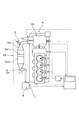
- Explanatory drawing which shows the internal combustion engine provided with the particulate-material detection apparatus which concerns on an Example.
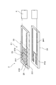
- Explanatory drawing which shows the particle amount detection means of the particulate matter detection apparatus which concerns on an Example.
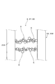
- the partial enlarged view which shows the particle amount detection means to which the particulate matter adhered.
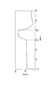
- the graph which shows the heating temperature by a heating means, and heating time in the particulate matter detection apparatus which concerns on an Example.
- the particle amount detection unit changes the output of the electric signal in accordance with a change in electric resistance between the pair of counter electrodes.
- the electric resistance type particle amount detection means utilizing the change in electric resistance value between the pair of counter electrodes has higher detection accuracy of the particulate matter and less variation than other types of particle amount detection means. . Therefore, it is possible to further improve the detection accuracy of the accumulation amount of the particulate matter.
- the heating of the particulate matter depositing portion by the heating means is continued until a predetermined operation time elapses from the start of the internal combustion engine. In this case, by continuing the heating until a predetermined operation time at which the condensed water is not generated in the exhaust gas, it is possible to reliably prevent water cracking and adhesion of the condensed water in the particulate matter depositing portion.
- the heating temperature of the particulate matter depositing portion in the heating means is set to 300 ° C. to 800 ° C.
- the Heating temperature by the heating means is less than 300 ° C.
- the Leidenfrost phenomenon does not occur between the particulate matter deposition part and the aggregated water, and the aggregated water may adhere to the particulate matter deposition part.
- the heating temperature by the heating means exceeds 800 ° C.
- water cracking may occur even if the Leidenfrost phenomenon occurs.
- the heating temperature of the particulate matter depositing portion in the heating means is preferably 400 ° C. to 700 ° C. In this case, it is possible to further improve the effect of suppressing the adhesion of condensed water and the occurrence of water cracking.
- the particulate matter detection device 1 includes a particle amount detection unit 2 that changes the output of an electrical signal in accordance with a change in electrical characteristics caused by the particulate matter 6 being deposited on the particulate matter deposition unit 22. And a temperature detecting means 3 for detecting the temperature of the exhaust gas, a control unit 4 for determining the amount of the particulate matter 6 deposited, and a heating means 24 for heating the particulate matter depositing portion 22.
- the particle amount detection means 2 is provided on the particulate matter accumulation unit 22 for depositing a part of the particulate matter 6 contained in the exhaust gas discharged from the internal combustion engine 5, and on the particulate matter accumulation unit 22. And a pair of counter electrodes 23 arranged apart from each other.
- the control unit 4 determines the accumulation amount of the particulate matter 6 in the particulate matter accumulation unit 22 based on the electric signal output by the particle amount detection means 2 and the temperature of the exhaust gas detected by the temperature detection means 3. Receive information about. Further, the control unit 4 heats the particulate matter depositing portion 22 to be heated to 300 ° C. to 800 ° C. when the internal combustion engine 5 is cold started when the exhaust gas temperature detected by the temperature detecting means 3 is 100 ° C. or less.
- the means 24 is controlled.
- the particulate matter detection device 1 is for detecting particulate matter 6 contained in exhaust gas discharged through an exhaust pipe 53 from an internal combustion engine 5 mounted on an automobile.
- the internal combustion engine 5 is a diesel engine equipped with a supercharger 51.
- the exhaust pipe 53 connected to the internal combustion engine 5 is provided with a purification system 52 including an oxidation catalyst (Diesel Oxidation Catalyst) 521 and a particulate filter (Diesel Particulate Filter) 522.
- the particulate matter detection device 1 includes a particle amount detection means 2 for detecting the amount of particulate matter 6 contained in the exhaust gas, a temperature detection means 3 for detecting the temperature of the exhaust gas flowing through the exhaust pipe 53, and a particle amount detection means. 2 and a control unit 4 for receiving the temperature information output from the temperature signal output from the temperature detection means 3.
- the temperature detecting means 3 is provided upstream of the purification system 52 in the exhaust pipe 53.
- the temperature detection means 3 is composed of a temperature sensor provided with a temperature sensing element, and is configured to be able to detect the temperature of exhaust gas flowing through the exhaust pipe 53. In this example, the temperature of the exhaust gas is detected by the temperature detection means 3, but the temperature of the exhaust pipe 53 may be detected.
- the particle amount detection means 2 is provided downstream of the purification system 52 in the exhaust pipe 53.
- the particle amount detection unit 2 is a PM sensor that detects the amount of the particulate matter 6, and includes a collection unit 21 that collects a part of the particulate matter 6 and a heating unit 24 that heats the collection unit 21. I have.
- the collection unit 21 includes a particulate matter deposition unit 22 that deposits the particulate matter 6 in the exhaust gas, and a pair of counter electrodes 23 that are arranged on the particulate matter deposition unit 22 so as to be separated from each other.
- the particulate matter depositing portion 22 has a substantially rectangular plate shape, and is formed of a ceramic material having electrical insulation.
- the ceramic material for example, alumina, zirconia, beryllia, mullite, silicon nitride, or the like can be used.
- the surface roughness in the particulate matter deposition part 22 was 2.0 ⁇ m as the 10-point average roughness.
- the reference length of the 10-point average roughness was 200 ⁇ m. Further, the reference length may conform to JIS B 0633.
- the pair of counter electrodes 23 is made of a conductive material, and is formed on the surface of the particulate matter deposition portion 22.
- the pair of counter electrodes 23 includes an electrode base portion 231 formed in parallel with the longitudinal direction in the particulate matter deposition portion 22 and a plurality of comb teeth portions 232 extending perpendicularly to the longitudinal direction from the electrode base portion 231.
- Each counter electrode 23 is arranged so that the electrode bases 231 face each other, and is arranged so that the comb teeth 232 in the other counter electrode 23 enter between the comb teeth 232 in one counter electrode 23. Yes.
- the particulate matter 6 is deposited on the particulate matter depositing portion 22, and the pair of counter electrodes 23 are electrically connected to each other by the particulate matter 6. Is reduced.
- a voltage is applied between the pair of counter electrodes 23, and the amount of current as an electric signal flowing between the counter electrodes 23 changes with a change in the electrical resistance value between the pair of counter electrodes 23.
- the current value output from the particle amount detection means 2 to the control unit 4 changes. That is, the current value output from the particle amount detection means 2 changes according to the amount of particulate matter 6 deposited in the particulate matter deposition section 22 and has information regarding the amount of particulate matter 6 deposited. It is.
- the control unit 4 includes a shunt resistor, and outputs a voltage calculated by the product of the output current value and the shunt resistor to an ECU (engine control unit).
- the heating means 24 has a heat wire 241 that generates heat by flowing a current supplied from a power source, and a heating base portion 242 made of an insulating material provided with the heat wire 241.
- the heating unit 24 is disposed so as to be laminated with the particulate matter deposition unit 22 on the side opposite to the side where the pair of counter electrodes 23 is disposed in the particulate matter deposition unit 22.
- the heating means 24 performs preheating for heating the particulate matter accumulation unit 22 during cold start of the internal combustion engine 5 and high temperature heating for removing the particulate matter 6 collected in the collection unit 21. It is configured.
- the preheating temperature can be set to 300 ° C to 800 ° C. In this example, the preheating temperature was 500 ° C. The preheating is performed in a state where the temperature of the exhaust gas detected by the temperature detecting means 3 is 100 ° C. or less.
- the temperature of the high temperature heating is set to 800 ° C.
- the high-temperature heating is newly performed after detecting the amount of the particulate matter 6 deposited or when the operation of the internal combustion engine 5 is stopped because the particulate matter 6 is not sufficiently deposited on the particulate matter accumulation portion 22. This is performed at a timing before the material 6 is deposited.
- control unit 4 controls the heating by the heating means 24 and the amount of the particulate matter 6 deposited in the particulate matter depositing unit 22 based on the output of the electric signal and the internal combustion engine 5 during the collection period. The total discharge amount of the discharged particulate matter 6 is calculated.
- FIG. 4 is a graph in which the horizontal axis is the operating time of the internal combustion engine and the vertical axis is the heating temperature in the heating means 24.
- the temperature detection means 3 detects the temperature of the exhaust gas discharged from the internal combustion engine 5.
- the control unit 4 determines that the engine is cold-started, and puts the heating unit 24 into a preheating state.
- the preliminary heating of the particulate matter deposition unit 22 by the heating unit 24 is continued until the predetermined operation time t1 is exceeded after the internal combustion engine 5 is started.
- the predetermined operation time t1 is 600 seconds.
- the predetermined operation time t1 exceeds 600 seconds, the preliminary heating of the heating means 24 is finished.
- the heating unit 24 is set to a high temperature heating state, and the particulate matter 6 deposited on the particulate matter accumulation unit 22 is removed by combustion.
- the heating unit 24 finishes the heating and starts collecting the particulate matter 6 in the collection unit 21.
- control unit 4 includes the deposition amount relationship data indicating the relationship between the output of the electrical signal and the deposition amount of the particulate matter 6 in the particulate matter deposition unit 22, and the particulate matter 6 in the particulate matter deposition unit 22.
- Emission amount relation data indicating the relationship between the accumulation amount and the total emission amount of the particulate matter 6 contained in the exhaust gas is stored.
- the accumulation amount-related data and the emission amount-related data are obtained in advance by performing a confirmation test in the internal combustion engine 5.
- the control unit 4 calculates the deposition amount of the particulate matter 6 using the deposition amount related data based on the output of the electrical signal. Then, the total discharge amount of the particulate matter 6 can be calculated using the discharge amount relation data based on the calculated deposition amount. As a result, the calculated total discharge amount of the particulate matter 6 is output to the control unit 4.
- the control unit 4 controls the heating means 24 to heat the particulate matter deposition part 22 to 300 ° C. to 800 ° C. when the internal combustion engine 5 is cold started. Therefore, water cracking in the particle amount detection means 2 and adhesion of condensed water can be suppressed. That is, when the particulate matter depositing part 22 is heated between 300 ° C. and 800 ° C., a Leidenfrost phenomenon can be caused between the particulate matter depositing part 22 and the condensed water.
- the aggregated water slides down from the particulate matter depositing portion 22 without contact between the particulate matter depositing portion 22 and the aggregated water due to the Leidenfrost phenomenon. Therefore, it is possible to prevent the aggregated water from adhering to the particulate matter depositing portion 22 and to suppress the particulate matter depositing portion 22 from being rapidly cooled by the adhering aggregated water. Thereby, it is possible to suppress various components contained in the condensed water from adhering to the particulate matter depositing portion 22 as residues and to prevent water cracking in the particulate matter depositing portion 22.
- the particle amount detection means 2 changes the output of the electric signal according to the change in the electric resistance between the pair of counter electrodes 23.
- the electric resistance type particle amount detection means 2 that utilizes the change in the electric resistance value between the pair of counter electrodes 23 has higher detection accuracy of the particulate matter 6 than the other types of particle amount detection means 2, and the variation thereof. Few. Therefore, it is possible to further improve the detection accuracy of the amount of particulate matter 6 deposited.
- the heating of the particulate matter depositing unit 22 by the heating unit 24 is continued until a predetermined operation time t1 has elapsed from the starting time ts of the internal combustion engine 5. Therefore, heating can be continued until the predetermined operation time t1 at which the condensed water does not occur in the exhaust gas, and adhesion of the aggregated water in the particulate matter depositing portion 22 can be reliably prevented.
- the timing of the preliminary heating of the particulate matter deposition unit 22 by the heating unit 24 is controlled by the operation time, but may be controlled by the temperature of the exhaust gas or the exhaust pipe.
- the internal combustion engine 5 continues from the start until the exhaust gas temperature detected by the temperature detecting means 3 exceeds 100 ° C. or until the exhaust pipe 53 temperature detected by the temperature detecting means 3 exceeds 60 ° C.
- the heating is continued until the temperature of the exhaust gas or the exhaust pipe 53 rises to a temperature at which the condensed gas does not occur in the exhaust gas, it is ensured that the particulate matter accumulation portion 22 is subjected to water cracking and the adhesion of the condensed water. Can be prevented.
- the particulate matter depositing part 22 is made of a ceramic material. Therefore, it is possible to improve the heat resistance in the particulate matter depositing portion 22 and further prevent the condensed water from adhering when the particulate matter depositing portion 22 is heated.
- the surface roughness Rz of the particulate matter depositing portion 22 is 0.01 ⁇ m ⁇ Rz ⁇ 4.0 ⁇ m as 10-point average roughness. Therefore, it is possible to more reliably prevent the condensed water from adhering to the particulate matter accumulation unit 22.
- the surface roughness Rz is less than 0.01 ⁇ m, it is advantageous for preventing adhesion of condensed water, but a desired surface roughness may not be obtained by processing.
- the surface roughness Rz exceeds 4.0 ⁇ m the contact angle between the condensed water and the particulate matter depositing part 22 is increased, wettability is increased, and the Leidenfrost phenomenon may not occur.
- the particulate matter detection device 1 can suppress water cracking and residue adhesion in the particle amount detection means 2.
- the heating temperature of the heating means 24 is set between 100 ° C. and 900 ° C. in increments of 100 ° C. in the particle amount detection means 2 shown in the embodiment as in the residue confirmation test.
- the agglomerated water is dropped into the particulate matter accumulation section 22 heated to each temperature.
- the amount of the condensed water dropped was 2 patterns of 1 ⁇ l and 1.5 ⁇ l.
- the heating temperature in the heating means 24 within the range of 300 ° C. to 800 ° C., it is possible to obtain the effect of suppressing the adhesion of residues and the effect of suppressing the occurrence of water cracking. Further, by setting the heating temperature in the heating means 24 within the range of 400 ° C. to 700 ° C., the effect of suppressing the adhesion of residues and the effect of suppressing the occurrence of water cracking can be further improved.
- the heating temperature was in the range of 350 ° C. to 800 ° C., no short circuit between the residue and the electrode was observed at any surface roughness Rz. Further, when the heating temperature was 300 ° C., no short circuit between the residue and the electrode was observed when the surface roughness Rz was 4.0 ⁇ m or less. When the heating temperature was 250 degrees, at least one of the residue and the short circuit between the electrodes occurred at any surface roughness Rz.
- the surface roughness Rz is desirably 4.0 ⁇ m or less, but is preferably 0.01 ⁇ m or more from the viewpoint of productivity.
Landscapes
- Engineering & Computer Science (AREA)
- Chemical & Material Sciences (AREA)
- General Engineering & Computer Science (AREA)
- Mechanical Engineering (AREA)
- Combustion & Propulsion (AREA)
- Pathology (AREA)
- Health & Medical Sciences (AREA)
- General Health & Medical Sciences (AREA)
- General Physics & Mathematics (AREA)
- Immunology (AREA)
- Analytical Chemistry (AREA)
- Life Sciences & Earth Sciences (AREA)
- Biochemistry (AREA)
- Physics & Mathematics (AREA)
- Dispersion Chemistry (AREA)
- Chemical Kinetics & Catalysis (AREA)
- Electrochemistry (AREA)
- Investigating Or Analyzing Materials By The Use Of Electric Means (AREA)
- Exhaust Gas After Treatment (AREA)
- Sampling And Sample Adjustment (AREA)
- Investigating Or Analyzing Materials Using Thermal Means (AREA)
Priority Applications (3)
| Application Number | Priority Date | Filing Date | Title |
|---|---|---|---|
| US15/319,541 US10208643B2 (en) | 2014-06-16 | 2015-06-12 | Particulate matter detection apparatus |
| CN201580032450.1A CN106460601B (zh) | 2014-06-16 | 2015-06-12 | 粒子状物质检测装置 |
| DE112015002836.6T DE112015002836T5 (de) | 2014-06-16 | 2015-06-12 | Partikelerfassungsvorrichtung |
Applications Claiming Priority (4)
| Application Number | Priority Date | Filing Date | Title |
|---|---|---|---|
| JP2014-123664 | 2014-06-16 | ||
| JP2014123664 | 2014-06-16 | ||
| JP2015028846A JP6248964B2 (ja) | 2014-06-16 | 2015-02-17 | 粒子状物質検出装置 |
| JP2015-028846 | 2015-02-17 |
Publications (1)
| Publication Number | Publication Date |
|---|---|
| WO2015194468A1 true WO2015194468A1 (ja) | 2015-12-23 |
Family
ID=54935455
Family Applications (1)
| Application Number | Title | Priority Date | Filing Date |
|---|---|---|---|
| PCT/JP2015/066978 Ceased WO2015194468A1 (ja) | 2014-06-16 | 2015-06-12 | 粒子状物質検出装置 |
Country Status (5)
| Country | Link |
|---|---|
| US (1) | US10208643B2 (enExample) |
| JP (1) | JP6248964B2 (enExample) |
| CN (1) | CN106460601B (enExample) |
| DE (1) | DE112015002836T5 (enExample) |
| WO (1) | WO2015194468A1 (enExample) |
Families Citing this family (8)
| Publication number | Priority date | Publication date | Assignee | Title |
|---|---|---|---|---|
| JP6365501B2 (ja) | 2015-10-21 | 2018-08-01 | 株式会社デンソー | 粒子状物質検出装置 |
| JP6579150B2 (ja) * | 2017-04-25 | 2019-09-25 | トヨタ自動車株式会社 | 排ガス浄化装置 |
| WO2019003612A1 (ja) * | 2017-06-27 | 2019-01-03 | 京セラ株式会社 | センサ基板およびセンサ装置 |
| DE112018004042T5 (de) * | 2017-09-06 | 2020-08-06 | Ngk Insulators, Ltd. | Teilchenerfassungselement und teilchendetektor |
| JP6964038B2 (ja) * | 2018-04-12 | 2021-11-10 | 株式会社Soken | 粒子状物質検出装置 |
| US10914223B1 (en) * | 2019-07-26 | 2021-02-09 | GM Global Technology Operations LLC | Particulate matter sensor hardware protection in after-run |
| CN111044424B (zh) * | 2019-12-13 | 2022-08-09 | 国网浙江省电力有限公司嘉兴供电公司 | 一种电力系统数据中心应急照明系统 |
| JP2022069317A (ja) * | 2020-10-23 | 2022-05-11 | トライポッド・デザイン株式会社 | 装置、センサ、センシング方法、センサシステム、及び発電方法 |
Citations (5)
| Publication number | Priority date | Publication date | Assignee | Title |
|---|---|---|---|---|
| JPH03238046A (ja) * | 1990-02-13 | 1991-10-23 | Toyota Motor Corp | ディーゼルエンジン用ハニカム触媒 |
| JPH05163934A (ja) * | 1991-12-17 | 1993-06-29 | Toyota Autom Loom Works Ltd | ディーゼル機関の排気ガス浄化装置 |
| JP2009529691A (ja) * | 2006-03-16 | 2009-08-20 | ロベルト・ボッシュ・ゲゼルシャフト・ミト・ベシュレンクテル・ハフツング | ガス・センサの作動方法および装置 |
| JP2011080926A (ja) * | 2009-10-09 | 2011-04-21 | Denso Corp | パティキュレート検出素子 |
| JP2012012960A (ja) * | 2010-06-29 | 2012-01-19 | Nippon Soken Inc | 粒子状物質検出センサ |
Family Cites Families (6)
| Publication number | Priority date | Publication date | Assignee | Title |
|---|---|---|---|---|
| JP3894125B2 (ja) * | 2003-01-28 | 2007-03-14 | 日産自動車株式会社 | 内燃機関の排気浄化装置 |
| US8136343B2 (en) * | 2009-09-02 | 2012-03-20 | Ford Global Technologies, Llc | System for an engine having a particulate matter sensor |
| US8230716B2 (en) * | 2009-11-09 | 2012-07-31 | Delphi Technologies, Inc. | Method and system for diagnostics of a particulate matter sensor |
| JP5408069B2 (ja) * | 2010-08-06 | 2014-02-05 | 株式会社デンソー | センサ制御装置及びこれを備える排気処理システム |
| US9617899B2 (en) * | 2012-12-05 | 2017-04-11 | Ford Global Technologies, Llc | Methods and systems for a particulate matter sensor |
| DE102013202980A1 (de) | 2013-02-22 | 2014-08-28 | Robert Bosch Gmbh | Verfahren und Vorrichtung zur Regeneration eines Partikelsensors |
-
2015
- 2015-02-17 JP JP2015028846A patent/JP6248964B2/ja active Active
- 2015-06-12 CN CN201580032450.1A patent/CN106460601B/zh not_active Expired - Fee Related
- 2015-06-12 US US15/319,541 patent/US10208643B2/en active Active
- 2015-06-12 WO PCT/JP2015/066978 patent/WO2015194468A1/ja not_active Ceased
- 2015-06-12 DE DE112015002836.6T patent/DE112015002836T5/de not_active Withdrawn
Patent Citations (5)
| Publication number | Priority date | Publication date | Assignee | Title |
|---|---|---|---|---|
| JPH03238046A (ja) * | 1990-02-13 | 1991-10-23 | Toyota Motor Corp | ディーゼルエンジン用ハニカム触媒 |
| JPH05163934A (ja) * | 1991-12-17 | 1993-06-29 | Toyota Autom Loom Works Ltd | ディーゼル機関の排気ガス浄化装置 |
| JP2009529691A (ja) * | 2006-03-16 | 2009-08-20 | ロベルト・ボッシュ・ゲゼルシャフト・ミト・ベシュレンクテル・ハフツング | ガス・センサの作動方法および装置 |
| JP2011080926A (ja) * | 2009-10-09 | 2011-04-21 | Denso Corp | パティキュレート検出素子 |
| JP2012012960A (ja) * | 2010-06-29 | 2012-01-19 | Nippon Soken Inc | 粒子状物質検出センサ |
Also Published As
| Publication number | Publication date |
|---|---|
| CN106460601A (zh) | 2017-02-22 |
| CN106460601B (zh) | 2019-09-03 |
| JP6248964B2 (ja) | 2017-12-20 |
| DE112015002836T5 (de) | 2017-03-09 |
| US20170122179A1 (en) | 2017-05-04 |
| JP2016020683A (ja) | 2016-02-04 |
| US10208643B2 (en) | 2019-02-19 |
Similar Documents
| Publication | Publication Date | Title |
|---|---|---|
| JP6248964B2 (ja) | 粒子状物質検出装置 | |
| JP5408069B2 (ja) | センサ制御装置及びこれを備える排気処理システム | |
| WO2012124054A1 (ja) | 内燃機関の制御装置 | |
| JP2016020683A5 (enExample) | ||
| JP6372789B2 (ja) | フィルタの故障診断装置 | |
| WO2017163650A1 (ja) | 粒子状物質検出装置 | |
| JP6481966B2 (ja) | 制御装置 | |
| JP6421617B2 (ja) | 粒子状物質検出センサ及び粒子状物質検出装置 | |
| CN108138625B (zh) | 颗粒状物质检测装置 | |
| JP6425993B2 (ja) | 粒子状物質検出素子 | |
| JP6365501B2 (ja) | 粒子状物質検出装置 | |
| JP6444063B2 (ja) | 粒子状物質検出装置及び粒子状物質検出方法 | |
| JP6256421B2 (ja) | フィルタ異常判定装置 | |
| JP6481967B2 (ja) | 制御装置 | |
| JP2012127268A (ja) | 内燃機関の制御装置 | |
| JP6511304B2 (ja) | 粒子状物質検出センサ | |
| JP6492035B2 (ja) | 粒子状物質検出装置 | |
| JP6358851B2 (ja) | 粒子状物質検出装置及び粒子状物質検出方法 | |
| JP6421736B2 (ja) | 粒子状物質検出装置 | |
| CN108474280B (zh) | 传感器控制装置 | |
| WO2019049570A1 (ja) | 微粒子数検出器 | |
| US11293849B2 (en) | Method for operating a sensor for detecting particles in a measuring gas | |
| JP2012087666A (ja) | フィルタの異常検出装置及び方法 | |
| JP2015222217A (ja) | 粒子状物質検出装置 |
Legal Events
| Date | Code | Title | Description |
|---|---|---|---|
| 121 | Ep: the epo has been informed by wipo that ep was designated in this application |
Ref document number: 15810107 Country of ref document: EP Kind code of ref document: A1 |
|
| WWE | Wipo information: entry into national phase |
Ref document number: 15319541 Country of ref document: US Ref document number: 112015002836 Country of ref document: DE |
|
| 122 | Ep: pct application non-entry in european phase |
Ref document number: 15810107 Country of ref document: EP Kind code of ref document: A1 |