WO2015194468A1 - Particulate matter detection device - Google Patents
Particulate matter detection device Download PDFInfo
- Publication number
- WO2015194468A1 WO2015194468A1 PCT/JP2015/066978 JP2015066978W WO2015194468A1 WO 2015194468 A1 WO2015194468 A1 WO 2015194468A1 JP 2015066978 W JP2015066978 W JP 2015066978W WO 2015194468 A1 WO2015194468 A1 WO 2015194468A1
- Authority
- WO
- WIPO (PCT)
- Prior art keywords
- particulate matter
- temperature
- heating
- exhaust gas
- detection means
- Prior art date
Links
Images
Classifications
-
- F—MECHANICAL ENGINEERING; LIGHTING; HEATING; WEAPONS; BLASTING
- F01—MACHINES OR ENGINES IN GENERAL; ENGINE PLANTS IN GENERAL; STEAM ENGINES
- F01N—GAS-FLOW SILENCERS OR EXHAUST APPARATUS FOR MACHINES OR ENGINES IN GENERAL; GAS-FLOW SILENCERS OR EXHAUST APPARATUS FOR INTERNAL COMBUSTION ENGINES
- F01N11/00—Monitoring or diagnostic devices for exhaust-gas treatment apparatus, e.g. for catalytic activity
- F01N11/002—Monitoring or diagnostic devices for exhaust-gas treatment apparatus, e.g. for catalytic activity the diagnostic devices measuring or estimating temperature or pressure in, or downstream of the exhaust apparatus
-
- F—MECHANICAL ENGINEERING; LIGHTING; HEATING; WEAPONS; BLASTING
- F01—MACHINES OR ENGINES IN GENERAL; ENGINE PLANTS IN GENERAL; STEAM ENGINES
- F01N—GAS-FLOW SILENCERS OR EXHAUST APPARATUS FOR MACHINES OR ENGINES IN GENERAL; GAS-FLOW SILENCERS OR EXHAUST APPARATUS FOR INTERNAL COMBUSTION ENGINES
- F01N3/00—Exhaust or silencing apparatus having means for purifying, rendering innocuous, or otherwise treating exhaust
- F01N3/02—Exhaust or silencing apparatus having means for purifying, rendering innocuous, or otherwise treating exhaust for cooling, or for removing solid constituents of, exhaust
- F01N3/021—Exhaust or silencing apparatus having means for purifying, rendering innocuous, or otherwise treating exhaust for cooling, or for removing solid constituents of, exhaust by means of filters
-
- F—MECHANICAL ENGINEERING; LIGHTING; HEATING; WEAPONS; BLASTING
- F02—COMBUSTION ENGINES; HOT-GAS OR COMBUSTION-PRODUCT ENGINE PLANTS
- F02D—CONTROLLING COMBUSTION ENGINES
- F02D41/00—Electrical control of supply of combustible mixture or its constituents
- F02D41/02—Circuit arrangements for generating control signals
- F02D41/04—Introducing corrections for particular operating conditions
- F02D41/06—Introducing corrections for particular operating conditions for engine starting or warming up
- F02D41/061—Introducing corrections for particular operating conditions for engine starting or warming up the corrections being time dependent
-
- F—MECHANICAL ENGINEERING; LIGHTING; HEATING; WEAPONS; BLASTING
- F02—COMBUSTION ENGINES; HOT-GAS OR COMBUSTION-PRODUCT ENGINE PLANTS
- F02D—CONTROLLING COMBUSTION ENGINES
- F02D41/00—Electrical control of supply of combustible mixture or its constituents
- F02D41/02—Circuit arrangements for generating control signals
- F02D41/04—Introducing corrections for particular operating conditions
- F02D41/06—Introducing corrections for particular operating conditions for engine starting or warming up
- F02D41/062—Introducing corrections for particular operating conditions for engine starting or warming up for starting
- F02D41/064—Introducing corrections for particular operating conditions for engine starting or warming up for starting at cold start
-
- F—MECHANICAL ENGINEERING; LIGHTING; HEATING; WEAPONS; BLASTING
- F02—COMBUSTION ENGINES; HOT-GAS OR COMBUSTION-PRODUCT ENGINE PLANTS
- F02D—CONTROLLING COMBUSTION ENGINES
- F02D41/00—Electrical control of supply of combustible mixture or its constituents
- F02D41/02—Circuit arrangements for generating control signals
- F02D41/14—Introducing closed-loop corrections
- F02D41/1438—Introducing closed-loop corrections using means for determining characteristics of the combustion gases; Sensors therefor
- F02D41/1444—Introducing closed-loop corrections using means for determining characteristics of the combustion gases; Sensors therefor characterised by the characteristics of the combustion gases
- F02D41/1446—Introducing closed-loop corrections using means for determining characteristics of the combustion gases; Sensors therefor characterised by the characteristics of the combustion gases the characteristics being exhaust temperatures
-
- F—MECHANICAL ENGINEERING; LIGHTING; HEATING; WEAPONS; BLASTING
- F02—COMBUSTION ENGINES; HOT-GAS OR COMBUSTION-PRODUCT ENGINE PLANTS
- F02D—CONTROLLING COMBUSTION ENGINES
- F02D41/00—Electrical control of supply of combustible mixture or its constituents
- F02D41/02—Circuit arrangements for generating control signals
- F02D41/14—Introducing closed-loop corrections
- F02D41/1438—Introducing closed-loop corrections using means for determining characteristics of the combustion gases; Sensors therefor
- F02D41/1444—Introducing closed-loop corrections using means for determining characteristics of the combustion gases; Sensors therefor characterised by the characteristics of the combustion gases
- F02D41/1466—Introducing closed-loop corrections using means for determining characteristics of the combustion gases; Sensors therefor characterised by the characteristics of the combustion gases the characteristics being a soot concentration or content
-
- F—MECHANICAL ENGINEERING; LIGHTING; HEATING; WEAPONS; BLASTING
- F02—COMBUSTION ENGINES; HOT-GAS OR COMBUSTION-PRODUCT ENGINE PLANTS
- F02D—CONTROLLING COMBUSTION ENGINES
- F02D41/00—Electrical control of supply of combustible mixture or its constituents
- F02D41/02—Circuit arrangements for generating control signals
- F02D41/14—Introducing closed-loop corrections
- F02D41/1438—Introducing closed-loop corrections using means for determining characteristics of the combustion gases; Sensors therefor
- F02D41/1493—Details
- F02D41/1494—Control of sensor heater
-
- F—MECHANICAL ENGINEERING; LIGHTING; HEATING; WEAPONS; BLASTING
- F02—COMBUSTION ENGINES; HOT-GAS OR COMBUSTION-PRODUCT ENGINE PLANTS
- F02D—CONTROLLING COMBUSTION ENGINES
- F02D41/00—Electrical control of supply of combustible mixture or its constituents
- F02D41/22—Safety or indicating devices for abnormal conditions
- F02D41/222—Safety or indicating devices for abnormal conditions relating to the failure of sensors or parameter detection devices
-
- G—PHYSICS
- G01—MEASURING; TESTING
- G01N—INVESTIGATING OR ANALYSING MATERIALS BY DETERMINING THEIR CHEMICAL OR PHYSICAL PROPERTIES
- G01N15/00—Investigating characteristics of particles; Investigating permeability, pore-volume, or surface-area of porous materials
- G01N15/06—Investigating concentration of particle suspensions
- G01N15/0606—Investigating concentration of particle suspensions by collecting particles on a support
-
- G—PHYSICS
- G01—MEASURING; TESTING
- G01N—INVESTIGATING OR ANALYSING MATERIALS BY DETERMINING THEIR CHEMICAL OR PHYSICAL PROPERTIES
- G01N15/00—Investigating characteristics of particles; Investigating permeability, pore-volume, or surface-area of porous materials
- G01N15/06—Investigating concentration of particle suspensions
- G01N15/0656—Investigating concentration of particle suspensions using electric, e.g. electrostatic methods or magnetic methods
-
- G—PHYSICS
- G01—MEASURING; TESTING
- G01N—INVESTIGATING OR ANALYSING MATERIALS BY DETERMINING THEIR CHEMICAL OR PHYSICAL PROPERTIES
- G01N27/00—Investigating or analysing materials by the use of electric, electrochemical, or magnetic means
- G01N27/02—Investigating or analysing materials by the use of electric, electrochemical, or magnetic means by investigating impedance
- G01N27/04—Investigating or analysing materials by the use of electric, electrochemical, or magnetic means by investigating impedance by investigating resistance
-
- F—MECHANICAL ENGINEERING; LIGHTING; HEATING; WEAPONS; BLASTING
- F01—MACHINES OR ENGINES IN GENERAL; ENGINE PLANTS IN GENERAL; STEAM ENGINES
- F01N—GAS-FLOW SILENCERS OR EXHAUST APPARATUS FOR MACHINES OR ENGINES IN GENERAL; GAS-FLOW SILENCERS OR EXHAUST APPARATUS FOR INTERNAL COMBUSTION ENGINES
- F01N2330/00—Structure of catalyst support or particle filter
- F01N2330/06—Ceramic, e.g. monoliths
-
- F—MECHANICAL ENGINEERING; LIGHTING; HEATING; WEAPONS; BLASTING
- F01—MACHINES OR ENGINES IN GENERAL; ENGINE PLANTS IN GENERAL; STEAM ENGINES
- F01N—GAS-FLOW SILENCERS OR EXHAUST APPARATUS FOR MACHINES OR ENGINES IN GENERAL; GAS-FLOW SILENCERS OR EXHAUST APPARATUS FOR INTERNAL COMBUSTION ENGINES
- F01N2560/00—Exhaust systems with means for detecting or measuring exhaust gas components or characteristics
- F01N2560/05—Exhaust systems with means for detecting or measuring exhaust gas components or characteristics the means being a particulate sensor
-
- F—MECHANICAL ENGINEERING; LIGHTING; HEATING; WEAPONS; BLASTING
- F01—MACHINES OR ENGINES IN GENERAL; ENGINE PLANTS IN GENERAL; STEAM ENGINES
- F01N—GAS-FLOW SILENCERS OR EXHAUST APPARATUS FOR MACHINES OR ENGINES IN GENERAL; GAS-FLOW SILENCERS OR EXHAUST APPARATUS FOR INTERNAL COMBUSTION ENGINES
- F01N2560/00—Exhaust systems with means for detecting or measuring exhaust gas components or characteristics
- F01N2560/06—Exhaust systems with means for detecting or measuring exhaust gas components or characteristics the means being a temperature sensor
-
- F—MECHANICAL ENGINEERING; LIGHTING; HEATING; WEAPONS; BLASTING
- F01—MACHINES OR ENGINES IN GENERAL; ENGINE PLANTS IN GENERAL; STEAM ENGINES
- F01N—GAS-FLOW SILENCERS OR EXHAUST APPARATUS FOR MACHINES OR ENGINES IN GENERAL; GAS-FLOW SILENCERS OR EXHAUST APPARATUS FOR INTERNAL COMBUSTION ENGINES
- F01N2900/00—Details of electrical control or of the monitoring of the exhaust gas treating apparatus
- F01N2900/06—Parameters used for exhaust control or diagnosing
- F01N2900/14—Parameters used for exhaust control or diagnosing said parameters being related to the exhaust gas
- F01N2900/1404—Exhaust gas temperature
-
- G—PHYSICS
- G01—MEASURING; TESTING
- G01N—INVESTIGATING OR ANALYSING MATERIALS BY DETERMINING THEIR CHEMICAL OR PHYSICAL PROPERTIES
- G01N15/00—Investigating characteristics of particles; Investigating permeability, pore-volume, or surface-area of porous materials
- G01N2015/0042—Investigating dispersion of solids
- G01N2015/0046—Investigating dispersion of solids in gas, e.g. smoke
-
- Y—GENERAL TAGGING OF NEW TECHNOLOGICAL DEVELOPMENTS; GENERAL TAGGING OF CROSS-SECTIONAL TECHNOLOGIES SPANNING OVER SEVERAL SECTIONS OF THE IPC; TECHNICAL SUBJECTS COVERED BY FORMER USPC CROSS-REFERENCE ART COLLECTIONS [XRACs] AND DIGESTS
- Y02—TECHNOLOGIES OR APPLICATIONS FOR MITIGATION OR ADAPTATION AGAINST CLIMATE CHANGE
- Y02T—CLIMATE CHANGE MITIGATION TECHNOLOGIES RELATED TO TRANSPORTATION
- Y02T10/00—Road transport of goods or passengers
- Y02T10/10—Internal combustion engine [ICE] based vehicles
- Y02T10/40—Engine management systems
Definitions
- the present invention relates to a particulate matter detection device for detecting the amount of particulate matter contained in exhaust gas generated from an internal combustion engine.
- An exhaust gas purification apparatus that collects particulate matter (PM) contained in the exhaust gas is provided in an exhaust pipe of the internal combustion engine.
- the exhaust gas purification apparatus includes a particulate matter detection device having a PM sensor that detects the amount of particulate matter contained in the exhaust gas, and the exhaust gas purification device is based on information obtained by the particulate matter detection device. Failure detection has been performed.
- the PM sensor used in the particulate matter detection device burns particulate matter adhering to the PM sensor by heating the PM sensor after the detection of the particulate matter and before the next detection is performed. Configured to remove.
- the particulate matter detection device disclosed in Patent Document 1 has the following problems.
- the particulate matter detection device disclosed in Patent Document 1 when the PM sensor is submerged without heating the PM sensor, condensed water adheres to the surface of the PM sensor.
- This condensed water may contain fuel, engine oil, exhaust pipe metal components, and the like. Therefore, when the condensed water adhering to the PM sensor is dried, the content of the condensed water remains on the surface of the PM sensor. These residues may cause PM sensor malfunctions or false detections.
- the present invention has been made in view of such a background, and an object of the present invention is to provide a particulate matter detection device capable of suppressing water cracking and adhesion of condensed water in the particle amount detection means.
- a particulate matter detection device is disposed apart from each other on a particulate matter accumulation part for depositing a part of particulate matter contained in exhaust gas discharged from an internal combustion engine, and the particulate matter accumulation part.
- a pair of counter electrodes, and a particle amount detecting means for changing an output of an electrical signal in accordance with a change in electrical characteristics caused by the particulate matter being deposited on the particulate matter accumulation portion, Temperature detecting means for detecting the temperature of exhaust gas or an exhaust pipe through which exhaust gas flows; and Based on the electrical signal output by the particle amount detection means, the amount of the particulate matter deposited in the particulate matter deposition portion is determined, and the temperature of the exhaust gas or the exhaust pipe detected by the temperature detection means
- the control unit controls the heating means so as to heat the particulate matter deposition part to 300 ° C. to 800 ° C. when the internal combustion engine is cold-started. Therefore, it is possible to suppress water cracking and adhesion of condensed water in the particle amount detection means. That is, when the particulate matter depositing part is heated to 300 ° C. to 800 ° C., a Leidenfrost effect can be generated between the particulate matter depositing part and the condensed water.
- the liquid is vaporized and evaporated at a portion where the solid heated above a predetermined temperature and the liquid are in contact with each other to form a vapor film.
- the vapor film forms the solid and the liquid. It will stop touching.
- a Leidenfrost phenomenon occurs between the particulate matter deposition part and the condensed water, and the particles The particulate matter accumulation part and the condensed water are not in contact with each other. Further, since the coagulated water floating on the water vapor film has a small coefficient of friction with the particulate matter depositing portion, it can easily move on the surface of the particulate matter depositing portion.
- the condensed water easily slides down from the particulate matter depositing part due to the Leidenfrost phenomenon. Accordingly, it is possible to prevent the aggregated water from adhering to the particulate matter depositing portion and to prevent the particulate matter depositing portion from being rapidly cooled by the adhering aggregated water. Thereby, the various components contained in the condensed water adhere to the particulate matter depositing portion as residues, and the occurrence of water cracking in the particulate matter depositing portion can be suppressed.
- the particulate matter detection device can suppress water cracking and residue adhesion in the particle amount detection means.
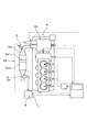
- Explanatory drawing which shows the internal combustion engine provided with the particulate-material detection apparatus which concerns on an Example.
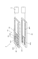
- Explanatory drawing which shows the particle amount detection means of the particulate matter detection apparatus which concerns on an Example.
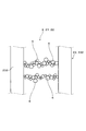
- the partial enlarged view which shows the particle amount detection means to which the particulate matter adhered.
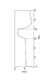
- the graph which shows the heating temperature by a heating means, and heating time in the particulate matter detection apparatus which concerns on an Example.
- the particle amount detection unit changes the output of the electric signal in accordance with a change in electric resistance between the pair of counter electrodes.
- the electric resistance type particle amount detection means utilizing the change in electric resistance value between the pair of counter electrodes has higher detection accuracy of the particulate matter and less variation than other types of particle amount detection means. . Therefore, it is possible to further improve the detection accuracy of the accumulation amount of the particulate matter.
- the heating of the particulate matter depositing portion by the heating means is continued until a predetermined operation time elapses from the start of the internal combustion engine. In this case, by continuing the heating until a predetermined operation time at which the condensed water is not generated in the exhaust gas, it is possible to reliably prevent water cracking and adhesion of the condensed water in the particulate matter depositing portion.
- the heating temperature of the particulate matter depositing portion in the heating means is set to 300 ° C. to 800 ° C.
- the Heating temperature by the heating means is less than 300 ° C.
- the Leidenfrost phenomenon does not occur between the particulate matter deposition part and the aggregated water, and the aggregated water may adhere to the particulate matter deposition part.
- the heating temperature by the heating means exceeds 800 ° C.
- water cracking may occur even if the Leidenfrost phenomenon occurs.
- the heating temperature of the particulate matter depositing portion in the heating means is preferably 400 ° C. to 700 ° C. In this case, it is possible to further improve the effect of suppressing the adhesion of condensed water and the occurrence of water cracking.
- the particulate matter detection device 1 includes a particle amount detection unit 2 that changes the output of an electrical signal in accordance with a change in electrical characteristics caused by the particulate matter 6 being deposited on the particulate matter deposition unit 22. And a temperature detecting means 3 for detecting the temperature of the exhaust gas, a control unit 4 for determining the amount of the particulate matter 6 deposited, and a heating means 24 for heating the particulate matter depositing portion 22.
- the particle amount detection means 2 is provided on the particulate matter accumulation unit 22 for depositing a part of the particulate matter 6 contained in the exhaust gas discharged from the internal combustion engine 5, and on the particulate matter accumulation unit 22. And a pair of counter electrodes 23 arranged apart from each other.
- the control unit 4 determines the accumulation amount of the particulate matter 6 in the particulate matter accumulation unit 22 based on the electric signal output by the particle amount detection means 2 and the temperature of the exhaust gas detected by the temperature detection means 3. Receive information about. Further, the control unit 4 heats the particulate matter depositing portion 22 to be heated to 300 ° C. to 800 ° C. when the internal combustion engine 5 is cold started when the exhaust gas temperature detected by the temperature detecting means 3 is 100 ° C. or less.
- the means 24 is controlled.
- the particulate matter detection device 1 is for detecting particulate matter 6 contained in exhaust gas discharged through an exhaust pipe 53 from an internal combustion engine 5 mounted on an automobile.
- the internal combustion engine 5 is a diesel engine equipped with a supercharger 51.
- the exhaust pipe 53 connected to the internal combustion engine 5 is provided with a purification system 52 including an oxidation catalyst (Diesel Oxidation Catalyst) 521 and a particulate filter (Diesel Particulate Filter) 522.
- the particulate matter detection device 1 includes a particle amount detection means 2 for detecting the amount of particulate matter 6 contained in the exhaust gas, a temperature detection means 3 for detecting the temperature of the exhaust gas flowing through the exhaust pipe 53, and a particle amount detection means. 2 and a control unit 4 for receiving the temperature information output from the temperature signal output from the temperature detection means 3.
- the temperature detecting means 3 is provided upstream of the purification system 52 in the exhaust pipe 53.
- the temperature detection means 3 is composed of a temperature sensor provided with a temperature sensing element, and is configured to be able to detect the temperature of exhaust gas flowing through the exhaust pipe 53. In this example, the temperature of the exhaust gas is detected by the temperature detection means 3, but the temperature of the exhaust pipe 53 may be detected.
- the particle amount detection means 2 is provided downstream of the purification system 52 in the exhaust pipe 53.
- the particle amount detection unit 2 is a PM sensor that detects the amount of the particulate matter 6, and includes a collection unit 21 that collects a part of the particulate matter 6 and a heating unit 24 that heats the collection unit 21. I have.
- the collection unit 21 includes a particulate matter deposition unit 22 that deposits the particulate matter 6 in the exhaust gas, and a pair of counter electrodes 23 that are arranged on the particulate matter deposition unit 22 so as to be separated from each other.
- the particulate matter depositing portion 22 has a substantially rectangular plate shape, and is formed of a ceramic material having electrical insulation.
- the ceramic material for example, alumina, zirconia, beryllia, mullite, silicon nitride, or the like can be used.
- the surface roughness in the particulate matter deposition part 22 was 2.0 ⁇ m as the 10-point average roughness.
- the reference length of the 10-point average roughness was 200 ⁇ m. Further, the reference length may conform to JIS B 0633.
- the pair of counter electrodes 23 is made of a conductive material, and is formed on the surface of the particulate matter deposition portion 22.
- the pair of counter electrodes 23 includes an electrode base portion 231 formed in parallel with the longitudinal direction in the particulate matter deposition portion 22 and a plurality of comb teeth portions 232 extending perpendicularly to the longitudinal direction from the electrode base portion 231.
- Each counter electrode 23 is arranged so that the electrode bases 231 face each other, and is arranged so that the comb teeth 232 in the other counter electrode 23 enter between the comb teeth 232 in one counter electrode 23. Yes.
- the particulate matter 6 is deposited on the particulate matter depositing portion 22, and the pair of counter electrodes 23 are electrically connected to each other by the particulate matter 6. Is reduced.
- a voltage is applied between the pair of counter electrodes 23, and the amount of current as an electric signal flowing between the counter electrodes 23 changes with a change in the electrical resistance value between the pair of counter electrodes 23.
- the current value output from the particle amount detection means 2 to the control unit 4 changes. That is, the current value output from the particle amount detection means 2 changes according to the amount of particulate matter 6 deposited in the particulate matter deposition section 22 and has information regarding the amount of particulate matter 6 deposited. It is.
- the control unit 4 includes a shunt resistor, and outputs a voltage calculated by the product of the output current value and the shunt resistor to an ECU (engine control unit).
- the heating means 24 has a heat wire 241 that generates heat by flowing a current supplied from a power source, and a heating base portion 242 made of an insulating material provided with the heat wire 241.
- the heating unit 24 is disposed so as to be laminated with the particulate matter deposition unit 22 on the side opposite to the side where the pair of counter electrodes 23 is disposed in the particulate matter deposition unit 22.
- the heating means 24 performs preheating for heating the particulate matter accumulation unit 22 during cold start of the internal combustion engine 5 and high temperature heating for removing the particulate matter 6 collected in the collection unit 21. It is configured.
- the preheating temperature can be set to 300 ° C to 800 ° C. In this example, the preheating temperature was 500 ° C. The preheating is performed in a state where the temperature of the exhaust gas detected by the temperature detecting means 3 is 100 ° C. or less.
- the temperature of the high temperature heating is set to 800 ° C.
- the high-temperature heating is newly performed after detecting the amount of the particulate matter 6 deposited or when the operation of the internal combustion engine 5 is stopped because the particulate matter 6 is not sufficiently deposited on the particulate matter accumulation portion 22. This is performed at a timing before the material 6 is deposited.
- control unit 4 controls the heating by the heating means 24 and the amount of the particulate matter 6 deposited in the particulate matter depositing unit 22 based on the output of the electric signal and the internal combustion engine 5 during the collection period. The total discharge amount of the discharged particulate matter 6 is calculated.
- FIG. 4 is a graph in which the horizontal axis is the operating time of the internal combustion engine and the vertical axis is the heating temperature in the heating means 24.
- the temperature detection means 3 detects the temperature of the exhaust gas discharged from the internal combustion engine 5.
- the control unit 4 determines that the engine is cold-started, and puts the heating unit 24 into a preheating state.
- the preliminary heating of the particulate matter deposition unit 22 by the heating unit 24 is continued until the predetermined operation time t1 is exceeded after the internal combustion engine 5 is started.
- the predetermined operation time t1 is 600 seconds.
- the predetermined operation time t1 exceeds 600 seconds, the preliminary heating of the heating means 24 is finished.
- the heating unit 24 is set to a high temperature heating state, and the particulate matter 6 deposited on the particulate matter accumulation unit 22 is removed by combustion.
- the heating unit 24 finishes the heating and starts collecting the particulate matter 6 in the collection unit 21.
- control unit 4 includes the deposition amount relationship data indicating the relationship between the output of the electrical signal and the deposition amount of the particulate matter 6 in the particulate matter deposition unit 22, and the particulate matter 6 in the particulate matter deposition unit 22.
- Emission amount relation data indicating the relationship between the accumulation amount and the total emission amount of the particulate matter 6 contained in the exhaust gas is stored.
- the accumulation amount-related data and the emission amount-related data are obtained in advance by performing a confirmation test in the internal combustion engine 5.
- the control unit 4 calculates the deposition amount of the particulate matter 6 using the deposition amount related data based on the output of the electrical signal. Then, the total discharge amount of the particulate matter 6 can be calculated using the discharge amount relation data based on the calculated deposition amount. As a result, the calculated total discharge amount of the particulate matter 6 is output to the control unit 4.
- the control unit 4 controls the heating means 24 to heat the particulate matter deposition part 22 to 300 ° C. to 800 ° C. when the internal combustion engine 5 is cold started. Therefore, water cracking in the particle amount detection means 2 and adhesion of condensed water can be suppressed. That is, when the particulate matter depositing part 22 is heated between 300 ° C. and 800 ° C., a Leidenfrost phenomenon can be caused between the particulate matter depositing part 22 and the condensed water.
- the aggregated water slides down from the particulate matter depositing portion 22 without contact between the particulate matter depositing portion 22 and the aggregated water due to the Leidenfrost phenomenon. Therefore, it is possible to prevent the aggregated water from adhering to the particulate matter depositing portion 22 and to suppress the particulate matter depositing portion 22 from being rapidly cooled by the adhering aggregated water. Thereby, it is possible to suppress various components contained in the condensed water from adhering to the particulate matter depositing portion 22 as residues and to prevent water cracking in the particulate matter depositing portion 22.
- the particle amount detection means 2 changes the output of the electric signal according to the change in the electric resistance between the pair of counter electrodes 23.
- the electric resistance type particle amount detection means 2 that utilizes the change in the electric resistance value between the pair of counter electrodes 23 has higher detection accuracy of the particulate matter 6 than the other types of particle amount detection means 2, and the variation thereof. Few. Therefore, it is possible to further improve the detection accuracy of the amount of particulate matter 6 deposited.
- the heating of the particulate matter depositing unit 22 by the heating unit 24 is continued until a predetermined operation time t1 has elapsed from the starting time ts of the internal combustion engine 5. Therefore, heating can be continued until the predetermined operation time t1 at which the condensed water does not occur in the exhaust gas, and adhesion of the aggregated water in the particulate matter depositing portion 22 can be reliably prevented.
- the timing of the preliminary heating of the particulate matter deposition unit 22 by the heating unit 24 is controlled by the operation time, but may be controlled by the temperature of the exhaust gas or the exhaust pipe.
- the internal combustion engine 5 continues from the start until the exhaust gas temperature detected by the temperature detecting means 3 exceeds 100 ° C. or until the exhaust pipe 53 temperature detected by the temperature detecting means 3 exceeds 60 ° C.
- the heating is continued until the temperature of the exhaust gas or the exhaust pipe 53 rises to a temperature at which the condensed gas does not occur in the exhaust gas, it is ensured that the particulate matter accumulation portion 22 is subjected to water cracking and the adhesion of the condensed water. Can be prevented.
- the particulate matter depositing part 22 is made of a ceramic material. Therefore, it is possible to improve the heat resistance in the particulate matter depositing portion 22 and further prevent the condensed water from adhering when the particulate matter depositing portion 22 is heated.
- the surface roughness Rz of the particulate matter depositing portion 22 is 0.01 ⁇ m ⁇ Rz ⁇ 4.0 ⁇ m as 10-point average roughness. Therefore, it is possible to more reliably prevent the condensed water from adhering to the particulate matter accumulation unit 22.
- the surface roughness Rz is less than 0.01 ⁇ m, it is advantageous for preventing adhesion of condensed water, but a desired surface roughness may not be obtained by processing.
- the surface roughness Rz exceeds 4.0 ⁇ m the contact angle between the condensed water and the particulate matter depositing part 22 is increased, wettability is increased, and the Leidenfrost phenomenon may not occur.
- the particulate matter detection device 1 can suppress water cracking and residue adhesion in the particle amount detection means 2.
- the heating temperature of the heating means 24 is set between 100 ° C. and 900 ° C. in increments of 100 ° C. in the particle amount detection means 2 shown in the embodiment as in the residue confirmation test.
- the agglomerated water is dropped into the particulate matter accumulation section 22 heated to each temperature.
- the amount of the condensed water dropped was 2 patterns of 1 ⁇ l and 1.5 ⁇ l.
- the heating temperature in the heating means 24 within the range of 300 ° C. to 800 ° C., it is possible to obtain the effect of suppressing the adhesion of residues and the effect of suppressing the occurrence of water cracking. Further, by setting the heating temperature in the heating means 24 within the range of 400 ° C. to 700 ° C., the effect of suppressing the adhesion of residues and the effect of suppressing the occurrence of water cracking can be further improved.
- the heating temperature was in the range of 350 ° C. to 800 ° C., no short circuit between the residue and the electrode was observed at any surface roughness Rz. Further, when the heating temperature was 300 ° C., no short circuit between the residue and the electrode was observed when the surface roughness Rz was 4.0 ⁇ m or less. When the heating temperature was 250 degrees, at least one of the residue and the short circuit between the electrodes occurred at any surface roughness Rz.
- the surface roughness Rz is desirably 4.0 ⁇ m or less, but is preferably 0.01 ⁇ m or more from the viewpoint of productivity.
Abstract
A particulate matter detection device (1) equipped with: a particle amount detection means (2); a temperature detection means (3) that detects the temperature of exhaust gas; a control unit (4); and a heating means (24). The particle amount detection means (2) is equipped with a particulate matter accumulation unit that accumulates a portion of the particulate matter contained in exhaust gas discharged from an internal combustion engine (5), and a pair of opposing electrodes arranged at a distance from each other on the particulate matter accumulation unit. The control unit (4) determines the amount of particulate matter accumulated in the particulate matter accumulation unit on the basis of an electrical signal output by the particle amount detection means (2), and receives information related to the exhaust gas temperature detected by the temperature detection means (3). During a cold startup of the internal combustion engine (5), the control unit (4) controls the heating means (24) so as to heat the particulate matter accumulation unit to 300-800°C.
Description
本発明は、内燃機関から発生した排ガスに含まれる粒子状物質の量を検出する粒子状物質検出装置に関する。
The present invention relates to a particulate matter detection device for detecting the amount of particulate matter contained in exhaust gas generated from an internal combustion engine.
内燃機関の排気管には、排ガスに含まれる粒子状物質(Particulate Matter:PM)を捕集する排ガス浄化装置が設けられている。この排ガス浄化装置は、排ガスに含まれる粒子状物質の量を検出するPMセンサを有する粒子状物質検出装置を備えており、この粒子状物質検出装置によって得られた情報を基に、排ガス浄化装置の故障検知が行われている。
粒子状物質検出装置に用いられるPMセンサは、粒子状物質の検出を終えた後、次回の検出を行うまでの間に、PMセンサを加熱することにより、PMセンサに付着した粒子状物質を燃焼除去するよう構成されている。 An exhaust gas purification apparatus that collects particulate matter (PM) contained in the exhaust gas is provided in an exhaust pipe of the internal combustion engine. The exhaust gas purification apparatus includes a particulate matter detection device having a PM sensor that detects the amount of particulate matter contained in the exhaust gas, and the exhaust gas purification device is based on information obtained by the particulate matter detection device. Failure detection has been performed.
The PM sensor used in the particulate matter detection device burns particulate matter adhering to the PM sensor by heating the PM sensor after the detection of the particulate matter and before the next detection is performed. Configured to remove.
ところで、内燃機関の冷間始動時には、排ガス中の水分が凝集した凝集水がPMセンサに付着することが考えられる。この凝集水の付着のタイミングが、上述のPMセンサの加熱のタイミングに重なると、PMセンサの被水割れを招く要因となることが懸念される。そこで、特許文献1の粒子状物質検出装置においては、内燃機関の冷間始動時の所定期間は、PMセンサにおける粒子状物質の燃焼除去のための加熱を行わないようにしている。
By the way, at the time of cold start of the internal combustion engine, it is conceivable that the condensed water in which the moisture in the exhaust gas is condensed adheres to the PM sensor. If the timing of adhesion of the condensed water overlaps with the timing of heating of the PM sensor described above, there is a concern that it may cause water cracking of the PM sensor. Therefore, in the particulate matter detection device of Patent Document 1, heating for removing the particulate matter in the PM sensor is not performed during a predetermined period when the internal combustion engine is cold-started.
しかしながら、特許文献1に示された粒子状物質検出装置には以下の課題がある。
特許文献1に示された粒子状物質検出装置において、PMセンサを加熱しない状態で、PMセンサが被水するとPMセンサの表面に凝集水が付着する。この凝集水には、燃料やエンジンオイル、排気管の金属成分等が含有されている場合がある。そのため、PMセンサに付着した凝集水が乾燥した際に、凝集水の含有物がPMセンサの表面に残留する。これら残留物によって、PMセンサの誤作動や誤検出が生じる場合がある。 However, the particulate matter detection device disclosed inPatent Document 1 has the following problems.
In the particulate matter detection device disclosed inPatent Document 1, when the PM sensor is submerged without heating the PM sensor, condensed water adheres to the surface of the PM sensor. This condensed water may contain fuel, engine oil, exhaust pipe metal components, and the like. Therefore, when the condensed water adhering to the PM sensor is dried, the content of the condensed water remains on the surface of the PM sensor. These residues may cause PM sensor malfunctions or false detections.
特許文献1に示された粒子状物質検出装置において、PMセンサを加熱しない状態で、PMセンサが被水するとPMセンサの表面に凝集水が付着する。この凝集水には、燃料やエンジンオイル、排気管の金属成分等が含有されている場合がある。そのため、PMセンサに付着した凝集水が乾燥した際に、凝集水の含有物がPMセンサの表面に残留する。これら残留物によって、PMセンサの誤作動や誤検出が生じる場合がある。 However, the particulate matter detection device disclosed in
In the particulate matter detection device disclosed in
本発明は、かかる背景に鑑みてなされたものであり、粒子量検出手段における被水割れ及び凝集水の付着を抑制することができる粒子状物質検出装置を提供しようとするものである。
The present invention has been made in view of such a background, and an object of the present invention is to provide a particulate matter detection device capable of suppressing water cracking and adhesion of condensed water in the particle amount detection means.
本発明に係る粒子状物質検出装置は、内燃機関から排出される排ガスに含まれる粒子状物質の一部を堆積させる粒子状物質堆積部と、該粒子状物質堆積部上に互いに離れて配置された一対の対向電極とを備えており、上記粒子状物質堆積部に上記粒子状物質が堆積することによる電気的特性の変化に応じて電気信号の出力を変化させる粒子量検出手段と、
排ガス又は排ガスを流通する排気管の温度を検出する温度検出手段と、
上記粒子量検出手段によって出力された上記電気信号を基に、上記粒子状物質堆積部における上記粒子状物質の堆積量を判定すると共に、上記温度検出手段によって検出された排ガス又は排気管の温度に関する情報を受信するコントロールユニットと、
上記粒子状物質堆積部を加熱するための加熱手段とを備えており、
上記コントロールユニットは、上記温度検出手段によって検出される排ガス温度が100℃以下、又は上記温度検出手段によって検出される排気管温度が60℃以下となる内燃機関の冷間始動時において、上記粒子状物質堆積部を300℃~800℃に加熱するよう該加熱手段を制御することを特徴とする。 A particulate matter detection device according to the present invention is disposed apart from each other on a particulate matter accumulation part for depositing a part of particulate matter contained in exhaust gas discharged from an internal combustion engine, and the particulate matter accumulation part. A pair of counter electrodes, and a particle amount detecting means for changing an output of an electrical signal in accordance with a change in electrical characteristics caused by the particulate matter being deposited on the particulate matter accumulation portion,
Temperature detecting means for detecting the temperature of exhaust gas or an exhaust pipe through which exhaust gas flows; and
Based on the electrical signal output by the particle amount detection means, the amount of the particulate matter deposited in the particulate matter deposition portion is determined, and the temperature of the exhaust gas or the exhaust pipe detected by the temperature detection means A control unit for receiving information;
Heating means for heating the particulate matter deposition part,
The control unit is configured such that when the internal combustion engine is cold-started when the exhaust gas temperature detected by the temperature detecting means is 100 ° C. or lower or the exhaust pipe temperature detected by the temperature detecting means is 60 ° C. or lower, The heating means is controlled to heat the material deposition portion to 300 ° C. to 800 ° C.
上記粒子状物質検出装置においては、上記コントロールユニットは、内燃機関の冷間始動時に、上記粒子状物質堆積部を300℃~800℃に加熱するよう該加熱手段を制御する。そのため、粒子量検出手段における被水割れ及び凝集水の付着を抑制することができる。すなわち、上記粒子状物質堆積部を300℃~800℃に加熱すると、上記粒子状物質堆積部と凝集水との間において、ライデンフロスト現象(Leidenfrost effect)を生じさせることができる。
In the particulate matter detection device, the control unit controls the heating means so as to heat the particulate matter deposition part to 300 ° C. to 800 ° C. when the internal combustion engine is cold-started. Therefore, it is possible to suppress water cracking and adhesion of condensed water in the particle amount detection means. That is, when the particulate matter depositing part is heated to 300 ° C. to 800 ° C., a Leidenfrost effect can be generated between the particulate matter depositing part and the condensed water.
ライデンフロスト現象とは、所定の温度以上に加熱された固体と、液体とが接触した部位において、液体が気化、蒸発して蒸気の膜を形成し、この蒸気の膜によって、固体と液体とが接触しなくなるというものである。上記粒子状物質検出装置においては、上記粒子状物質堆積部を300℃~800℃に加熱することにより、上記粒子状物質堆積部と凝集水との間において、ライデンフロスト現象が発生し、上記粒子状物質堆積部と凝集水とが接触しなくなる。また、水蒸気の膜の上に浮いた状態の凝集水は、上記粒子状物質堆積部との間における摩擦係数が小さくなるため、上記粒子状物質堆積部の表面を容易に移動することができる。
In the Leidenfrost phenomenon, the liquid is vaporized and evaporated at a portion where the solid heated above a predetermined temperature and the liquid are in contact with each other to form a vapor film. The vapor film forms the solid and the liquid. It will stop touching. In the particulate matter detection device, by heating the particulate matter deposition part to 300 ° C. to 800 ° C., a Leidenfrost phenomenon occurs between the particulate matter deposition part and the condensed water, and the particles The particulate matter accumulation part and the condensed water are not in contact with each other. Further, since the coagulated water floating on the water vapor film has a small coefficient of friction with the particulate matter depositing portion, it can easily move on the surface of the particulate matter depositing portion.
そのため、加熱された上記粒子状物質堆積部が被水したとしても、ライデンフロスト現象によって、上記粒子状物質堆積部から凝集水が容易に滑り落ちる。したがって、上記粒子状物質堆積部における凝集水の付着を防止すると共に、凝集水が付着することによって上記粒子状物質堆積部が急冷されることを抑制できる。これにより、上記粒子状物質堆積部に、凝集水に含まれた種々の成分が残留物として付着すること、及び上記粒子状物質堆積部における被水割れの発生を抑制することができる。
Therefore, even if the heated particulate matter depositing part is wetted, the condensed water easily slides down from the particulate matter depositing part due to the Leidenfrost phenomenon. Accordingly, it is possible to prevent the aggregated water from adhering to the particulate matter depositing portion and to prevent the particulate matter depositing portion from being rapidly cooled by the adhering aggregated water. Thereby, the various components contained in the condensed water adhere to the particulate matter depositing portion as residues, and the occurrence of water cracking in the particulate matter depositing portion can be suppressed.
以上のごとく、上記粒子状物質検出装置は、粒子量検出手段における被水割れ及び残留物の付着を抑制することができる。
As described above, the particulate matter detection device can suppress water cracking and residue adhesion in the particle amount detection means.
上記粒子状物質検出装置において、上記粒子量検出手段は、上記一対の対向電極間における電気抵抗の変化に応じて上記電気信号の出力を変化させることが好ましい。上記一対の対向電極間における電気抵抗値の変化を利用する電気抵抗式の上記粒子量検出手段は、他の形式の粒子量検出手段と比べて上記粒子状物質の検出精度が高く、ばらつきが少ない。したがって、上記粒子状物質の堆積量の検出精度をより向上することができる。
In the particulate matter detection device, it is preferable that the particle amount detection unit changes the output of the electric signal in accordance with a change in electric resistance between the pair of counter electrodes. The electric resistance type particle amount detection means utilizing the change in electric resistance value between the pair of counter electrodes has higher detection accuracy of the particulate matter and less variation than other types of particle amount detection means. . Therefore, it is possible to further improve the detection accuracy of the accumulation amount of the particulate matter.
また、上記加熱手段による上記粒子状物質堆積部の加熱は、内燃機関の始動時から所定の運転時間を経過するまで継続することが好ましい。この場合には、排ガスにおいて凝集水が発生しなくなる所定の運転時間まで加熱を継続することにより、上記粒子状物質堆積部における被水割れ及び凝集水の付着を確実に防止することができる。
Further, it is preferable that the heating of the particulate matter depositing portion by the heating means is continued until a predetermined operation time elapses from the start of the internal combustion engine. In this case, by continuing the heating until a predetermined operation time at which the condensed water is not generated in the exhaust gas, it is possible to reliably prevent water cracking and adhesion of the condensed water in the particulate matter depositing portion.
また、上記加熱手段における上記粒子状物質堆積部の加熱温度は、300℃~800℃に設定してある。上記加熱手段による加熱温度が300℃未満の場合、上記粒子状物質堆積部と凝集水との間においてライデンフロスト現象が生じず、上記粒子状物質堆積部に凝集水が付着するおそれがある。また、上記加熱手段による加熱温度が800℃を超える場合、ライデンフロスト現象が生じたとしても被水割れが生じるおそれがある。
また、上記加熱手段における上記粒子状物質堆積部の加熱温度は、400℃~700℃とすることが好ましい。この場合には、凝集水の付着の抑制及び被水割れの発生の抑制効果をより向上することができる。 Further, the heating temperature of the particulate matter depositing portion in the heating means is set to 300 ° C. to 800 ° C. When the heating temperature by the heating means is less than 300 ° C., the Leidenfrost phenomenon does not occur between the particulate matter deposition part and the aggregated water, and the aggregated water may adhere to the particulate matter deposition part. Further, when the heating temperature by the heating means exceeds 800 ° C., water cracking may occur even if the Leidenfrost phenomenon occurs.
Further, the heating temperature of the particulate matter depositing portion in the heating means is preferably 400 ° C. to 700 ° C. In this case, it is possible to further improve the effect of suppressing the adhesion of condensed water and the occurrence of water cracking.
一実施例に係る粒子状物質検出装置について、図1~図4を参照しながら説明する。
図1に示すごとく、粒子状物質検出装置1は、粒子状物質堆積部22に粒子状物質6が堆積することによる電気的特性の変化に応じて電気信号の出力を変化させる粒子量検出手段2と、排ガスの温度を検出する温度検出手段3と、粒子状物質6の堆積量を判定するコントロールユニット4と、粒子状物質堆積部22を加熱する加熱手段24とを備えている。 A particulate matter detection device according to one embodiment will be described with reference to FIGS.
As shown in FIG. 1, the particulatematter detection device 1 includes a particle amount detection unit 2 that changes the output of an electrical signal in accordance with a change in electrical characteristics caused by the particulate matter 6 being deposited on the particulate matter deposition unit 22. And a temperature detecting means 3 for detecting the temperature of the exhaust gas, a control unit 4 for determining the amount of the particulate matter 6 deposited, and a heating means 24 for heating the particulate matter depositing portion 22.
図1に示すごとく、粒子状物質検出装置1は、粒子状物質堆積部22に粒子状物質6が堆積することによる電気的特性の変化に応じて電気信号の出力を変化させる粒子量検出手段2と、排ガスの温度を検出する温度検出手段3と、粒子状物質6の堆積量を判定するコントロールユニット4と、粒子状物質堆積部22を加熱する加熱手段24とを備えている。 A particulate matter detection device according to one embodiment will be described with reference to FIGS.
As shown in FIG. 1, the particulate
図2に示すごとく、粒子量検出手段2は、内燃機関5から排出される排ガスに含まれる粒子状物質6の一部を堆積させる粒子状物質堆積部22と、粒子状物質堆積部22上に互いに離れて配置された一対の対向電極23とを備えている。コントロールユニット4は、粒子量検出手段2によって出力された電気信号を基に、粒子状物質堆積部22における粒子状物質6の堆積量を判定すると共に、温度検出手段3によって検出された排ガスの温度に関する情報を受信する。また、コントロールユニット4は、温度検出手段3によって検出される排ガス温度が100℃以下となる内燃機関5の冷間始動時において、粒子状物質堆積部22を300℃~800℃に加熱するよう加熱手段24を制御する。
As shown in FIG. 2, the particle amount detection means 2 is provided on the particulate matter accumulation unit 22 for depositing a part of the particulate matter 6 contained in the exhaust gas discharged from the internal combustion engine 5, and on the particulate matter accumulation unit 22. And a pair of counter electrodes 23 arranged apart from each other. The control unit 4 determines the accumulation amount of the particulate matter 6 in the particulate matter accumulation unit 22 based on the electric signal output by the particle amount detection means 2 and the temperature of the exhaust gas detected by the temperature detection means 3. Receive information about. Further, the control unit 4 heats the particulate matter depositing portion 22 to be heated to 300 ° C. to 800 ° C. when the internal combustion engine 5 is cold started when the exhaust gas temperature detected by the temperature detecting means 3 is 100 ° C. or less. The means 24 is controlled.
以下、本実施例に係る粒子状物質検出装置の構成について、さらに詳細に説明する。
図1に示すごとく、粒子状物質検出装置1は、自動車に搭載された内燃機関5から、排気管53を通じて排出される排ガスに含まれる粒子状物質6を検出するためのものである。本例において、内燃機関5は、過給器51を搭載したディーゼルエンジンである。また、内燃機関5に接続された排気管53には、酸化触媒(Diesel Oxidation Catalyst)521及びパティキュレートフィルタ(Diesel Particulate Filter)522を備えた浄化システム52が設けられている。 Hereinafter, the configuration of the particulate matter detection device according to the present embodiment will be described in more detail.
As shown in FIG. 1, the particulatematter detection device 1 is for detecting particulate matter 6 contained in exhaust gas discharged through an exhaust pipe 53 from an internal combustion engine 5 mounted on an automobile. In this example, the internal combustion engine 5 is a diesel engine equipped with a supercharger 51. The exhaust pipe 53 connected to the internal combustion engine 5 is provided with a purification system 52 including an oxidation catalyst (Diesel Oxidation Catalyst) 521 and a particulate filter (Diesel Particulate Filter) 522.
図1に示すごとく、粒子状物質検出装置1は、自動車に搭載された内燃機関5から、排気管53を通じて排出される排ガスに含まれる粒子状物質6を検出するためのものである。本例において、内燃機関5は、過給器51を搭載したディーゼルエンジンである。また、内燃機関5に接続された排気管53には、酸化触媒(Diesel Oxidation Catalyst)521及びパティキュレートフィルタ(Diesel Particulate Filter)522を備えた浄化システム52が設けられている。 Hereinafter, the configuration of the particulate matter detection device according to the present embodiment will be described in more detail.
As shown in FIG. 1, the particulate
粒子状物質検出装置1は、排ガスに含まれる粒子状物質6の量を検出する粒子量検出手段2と、排気管53を流通する排ガスの温度を検出する温度検出手段3と、粒子量検出手段2から出力された電気信号及び温度検出手段3から出力された温度情報を受信するコントロールユニット4とを備えている。
The particulate matter detection device 1 includes a particle amount detection means 2 for detecting the amount of particulate matter 6 contained in the exhaust gas, a temperature detection means 3 for detecting the temperature of the exhaust gas flowing through the exhaust pipe 53, and a particle amount detection means. 2 and a control unit 4 for receiving the temperature information output from the temperature signal output from the temperature detection means 3.
温度検出手段3は、排気管53における浄化システム52の上流側に設けてある。温度検出手段3は、感温素子を備えた温度センサからなり、排気管53を流通する排ガスの温度を検出可能に構成されている。尚、本例においては、温度検出手段3によって、排ガスの温度を検出したが、排気管53の温度を検出してもよい。
The temperature detecting means 3 is provided upstream of the purification system 52 in the exhaust pipe 53. The temperature detection means 3 is composed of a temperature sensor provided with a temperature sensing element, and is configured to be able to detect the temperature of exhaust gas flowing through the exhaust pipe 53. In this example, the temperature of the exhaust gas is detected by the temperature detection means 3, but the temperature of the exhaust pipe 53 may be detected.
図2及び図3に示すごとく、粒子量検出手段2は、排気管53における浄化システム52の下流側に設けてある。粒子量検出手段2は、粒子状物質6の量を検出するPMセンサであり、粒子状物質6の一部を捕集する捕集部21と、捕集部21を加熱する加熱手段24とを備えている。
As shown in FIGS. 2 and 3, the particle amount detection means 2 is provided downstream of the purification system 52 in the exhaust pipe 53. The particle amount detection unit 2 is a PM sensor that detects the amount of the particulate matter 6, and includes a collection unit 21 that collects a part of the particulate matter 6 and a heating unit 24 that heats the collection unit 21. I have.
捕集部21は、排ガス中の粒子状物質6を堆積させる粒子状物質堆積部22と、粒子状物質堆積部22上に互いに離れて配置された一対の対向電極23とを備えている。粒子状物質堆積部22は、略長方形の板状をなしており、電気絶縁性を備えたセラミックス材料によって形成されている。セラミックス材料としては、例えば、アルミナ、ジルコニア、ベリリア、ムライト、窒化珪素等を用いることができる。また、粒子状物質堆積部22における表面粗度は、10点平均粗さとして、2.0μmとした。本例において、10点平均粗さの基準長さは、200μmとした。また、基準長さは、JIS B 0633に準ずるものであってもよい。
The collection unit 21 includes a particulate matter deposition unit 22 that deposits the particulate matter 6 in the exhaust gas, and a pair of counter electrodes 23 that are arranged on the particulate matter deposition unit 22 so as to be separated from each other. The particulate matter depositing portion 22 has a substantially rectangular plate shape, and is formed of a ceramic material having electrical insulation. As the ceramic material, for example, alumina, zirconia, beryllia, mullite, silicon nitride, or the like can be used. Moreover, the surface roughness in the particulate matter deposition part 22 was 2.0 μm as the 10-point average roughness. In this example, the reference length of the 10-point average roughness was 200 μm. Further, the reference length may conform to JIS B 0633.
一対の対向電極23は、導電性材料からなり、粒子状物質堆積部22の表面に形成されている。一対の対向電極23は、粒子状物質堆積部22における長手方向と平行に形成された電極基部231と、電極基部231から長手方向と直交して延設された複数の櫛歯部232とをそれぞれ有している。各対向電極23は、電極基部231が互いに向かい合うように配置されると共に、一方の対向電極23における櫛歯部232の間に、他方の対向電極23における櫛歯部232が入り込むように配置されている。
The pair of counter electrodes 23 is made of a conductive material, and is formed on the surface of the particulate matter deposition portion 22. The pair of counter electrodes 23 includes an electrode base portion 231 formed in parallel with the longitudinal direction in the particulate matter deposition portion 22 and a plurality of comb teeth portions 232 extending perpendicularly to the longitudinal direction from the electrode base portion 231. Have. Each counter electrode 23 is arranged so that the electrode bases 231 face each other, and is arranged so that the comb teeth 232 in the other counter electrode 23 enter between the comb teeth 232 in one counter electrode 23. Yes.
図3に示すごとく、粒子状物質堆積部22に粒子状物質6が堆積し、一対の対向電極23の間が粒子状物質6によって導通されることで、一対の対向電極23間の電気抵抗値が低減する。一対の対向電極23の間には電圧が印加されており、一対の対向電極23間の電気抵抗値の変化に伴い、対向電極23間を流れる電気信号としての電流量が変化する。これにより、粒子量検出手段2からコントロールユニット4へと出力される電流値が変化する。つまり、粒子量検出手段2から出力される電流値は、粒子状物質堆積部22における粒子状物質6の堆積量に応じて変化するものであり、粒子状物質6の堆積量に関する情報を有するものである。コントロールユニット4は、シャント抵抗を備えており、出力された電流値とシャント抵抗の積で算出される電圧をECU(エンジンコントロールユニット)へと出力する。
As shown in FIG. 3, the particulate matter 6 is deposited on the particulate matter depositing portion 22, and the pair of counter electrodes 23 are electrically connected to each other by the particulate matter 6. Is reduced. A voltage is applied between the pair of counter electrodes 23, and the amount of current as an electric signal flowing between the counter electrodes 23 changes with a change in the electrical resistance value between the pair of counter electrodes 23. Thereby, the current value output from the particle amount detection means 2 to the control unit 4 changes. That is, the current value output from the particle amount detection means 2 changes according to the amount of particulate matter 6 deposited in the particulate matter deposition section 22 and has information regarding the amount of particulate matter 6 deposited. It is. The control unit 4 includes a shunt resistor, and outputs a voltage calculated by the product of the output current value and the shunt resistor to an ECU (engine control unit).
図2に示すごとく、加熱手段24は、電源から供給される電流を流通することで発熱する熱線241と、熱線241が配設された絶縁性材料からなる加熱基部242とを有している。加熱手段24は、粒子状物質堆積部22における一対の対向電極23が配置された側と反対側に、粒子状物質堆積部22と積層して配置されている。加熱手段24は、内燃機関5の冷間始動時に粒子状物質堆積部22を加熱する予備加熱と、捕集部21に捕集された粒子状物質6を除去するための高温加熱とを行うように構成されている。
As shown in FIG. 2, the heating means 24 has a heat wire 241 that generates heat by flowing a current supplied from a power source, and a heating base portion 242 made of an insulating material provided with the heat wire 241. The heating unit 24 is disposed so as to be laminated with the particulate matter deposition unit 22 on the side opposite to the side where the pair of counter electrodes 23 is disposed in the particulate matter deposition unit 22. The heating means 24 performs preheating for heating the particulate matter accumulation unit 22 during cold start of the internal combustion engine 5 and high temperature heating for removing the particulate matter 6 collected in the collection unit 21. It is configured.
予備加熱の温度は、300℃~800℃に設定することができる。本例においては、予備加熱の温度を500℃とした。予備加熱は、温度検出手段3によって検出された排ガスの温度が100℃以下の状態において行われる。
The preheating temperature can be set to 300 ° C to 800 ° C. In this example, the preheating temperature was 500 ° C. The preheating is performed in a state where the temperature of the exhaust gas detected by the temperature detecting means 3 is 100 ° C. or less.
また、高温加熱の温度は、800℃に設定してある。高温加熱は、粒子状物質6の堆積量を検出した後や、粒子状物質堆積部22に粒子状物質6が十分堆積せずに内燃機関5の運転が停止した場合等に、新たに粒子状物質6を堆積させる前のタイミングにおいて行われる。
Also, the temperature of the high temperature heating is set to 800 ° C. The high-temperature heating is newly performed after detecting the amount of the particulate matter 6 deposited or when the operation of the internal combustion engine 5 is stopped because the particulate matter 6 is not sufficiently deposited on the particulate matter accumulation portion 22. This is performed at a timing before the material 6 is deposited.
本例において、コントロールユニット4は、加熱手段24による加熱の制御と、電気信号の出力に基づいて粒子状物質堆積部22における粒子状物質6の堆積量及び、捕集期間中に内燃機関5から排出された粒子状物質6の総排出量の算出を行う。
In this example, the control unit 4 controls the heating by the heating means 24 and the amount of the particulate matter 6 deposited in the particulate matter depositing unit 22 based on the output of the electric signal and the internal combustion engine 5 during the collection period. The total discharge amount of the discharged particulate matter 6 is calculated.
図4に示すごとく、本例において、コントロールユニット4による加熱手段24の制御は、温度検出手段3によって検出された温度情報を利用して行われる。図4は、横軸を内燃機関の運転時間として、縦軸を加熱手段24における加熱温度としたグラフである。内燃機関5の始動時(ts)、温度検出手段3によって内燃機関5から排出される排ガスの温度を検出する。このとき、排ガスの温度が100℃以下であった場合、コントロールユニット4は、冷間始動と判断し、加熱手段24を予備加熱状態とする。そして、内燃機関5の始動から所定の運転時間t1を超えるまでの間、加熱手段24による粒子状物質堆積部22の予備加熱を継続する。本例においては、所定の運転時間t1を600秒とした。所定の運転時間t1が600秒を超えた際に、加熱手段24の予備加熱を終了する。本例においては、予備加熱が終了した後、加熱手段24を高温加熱状態として、粒子状物質堆積部22上に堆積した粒子状物質6を燃焼除去する。運転時間t2において、粒子状物質堆積部22の粒子状物質6の燃焼除去が完了すると、加熱手段24は加熱を終了し、捕集部21への粒子状物質6の捕集を開始する。
As shown in FIG. 4, in this example, the control of the heating means 24 by the control unit 4 is performed using temperature information detected by the temperature detection means 3. FIG. 4 is a graph in which the horizontal axis is the operating time of the internal combustion engine and the vertical axis is the heating temperature in the heating means 24. When the internal combustion engine 5 is started (ts), the temperature detection means 3 detects the temperature of the exhaust gas discharged from the internal combustion engine 5. At this time, when the temperature of the exhaust gas is 100 ° C. or less, the control unit 4 determines that the engine is cold-started, and puts the heating unit 24 into a preheating state. Then, the preliminary heating of the particulate matter deposition unit 22 by the heating unit 24 is continued until the predetermined operation time t1 is exceeded after the internal combustion engine 5 is started. In this example, the predetermined operation time t1 is 600 seconds. When the predetermined operation time t1 exceeds 600 seconds, the preliminary heating of the heating means 24 is finished. In this example, after the preliminary heating is completed, the heating unit 24 is set to a high temperature heating state, and the particulate matter 6 deposited on the particulate matter accumulation unit 22 is removed by combustion. When the combustion removal of the particulate matter 6 in the particulate matter accumulation unit 22 is completed at the operation time t2, the heating unit 24 finishes the heating and starts collecting the particulate matter 6 in the collection unit 21.
また、コントロールユニット4は、電気信号の出力と粒子状物質堆積部22における粒子状物質6の堆積量との関係を示した堆積量関係データと、粒子状物質堆積部22における粒子状物質6の堆積量と排ガスに含まれる粒子状物質6の総排出量との関係を示した排出量関係データとを記憶している。堆積量関係データ及び排出量関係データは、内燃機関5において確認試験を実施し、予め求めたものである。コントロールユニット4は、電気信号の出力を基に堆積量関係データを用いて粒子状物質6の堆積量を算出する。そして、算出された堆積量を基に排出量関係データを用いて粒子状物質6の総排出量を算出することができる。これにより、算出された粒子状物質6の総排出量が、コントロールユニット4に出力される。
In addition, the control unit 4 includes the deposition amount relationship data indicating the relationship between the output of the electrical signal and the deposition amount of the particulate matter 6 in the particulate matter deposition unit 22, and the particulate matter 6 in the particulate matter deposition unit 22. Emission amount relation data indicating the relationship between the accumulation amount and the total emission amount of the particulate matter 6 contained in the exhaust gas is stored. The accumulation amount-related data and the emission amount-related data are obtained in advance by performing a confirmation test in the internal combustion engine 5. The control unit 4 calculates the deposition amount of the particulate matter 6 using the deposition amount related data based on the output of the electrical signal. Then, the total discharge amount of the particulate matter 6 can be calculated using the discharge amount relation data based on the calculated deposition amount. As a result, the calculated total discharge amount of the particulate matter 6 is output to the control unit 4.
次に、本例の作用効果について説明する。
粒子状物質検出装置1においては、コントロールユニット4は、内燃機関5の冷間始動時に、粒子状物質堆積部22を300℃~800℃に加熱するよう加熱手段24を制御する。そのため、粒子量検出手段2における被水割れ及び凝集水の付着を抑制することができる。すなわち、粒子状物質堆積部22を300℃~800℃の間に加熱すると、粒子状物質堆積部22と凝集水との間において、ライデンフロスト現象を生じさせることができる。 Next, the function and effect of this example will be described.
In the particulatematter detection device 1, the control unit 4 controls the heating means 24 to heat the particulate matter deposition part 22 to 300 ° C. to 800 ° C. when the internal combustion engine 5 is cold started. Therefore, water cracking in the particle amount detection means 2 and adhesion of condensed water can be suppressed. That is, when the particulate matter depositing part 22 is heated between 300 ° C. and 800 ° C., a Leidenfrost phenomenon can be caused between the particulate matter depositing part 22 and the condensed water.
粒子状物質検出装置1においては、コントロールユニット4は、内燃機関5の冷間始動時に、粒子状物質堆積部22を300℃~800℃に加熱するよう加熱手段24を制御する。そのため、粒子量検出手段2における被水割れ及び凝集水の付着を抑制することができる。すなわち、粒子状物質堆積部22を300℃~800℃の間に加熱すると、粒子状物質堆積部22と凝集水との間において、ライデンフロスト現象を生じさせることができる。 Next, the function and effect of this example will be described.
In the particulate
そのため、粒子状物質堆積部22が被水したとしても、ライデンフロスト現象によって粒子状物質堆積部22と凝集水とは接触することなく、粒子状物質堆積部22から凝集水が滑り落ちる。したがって、粒子状物質堆積部22における凝集水の付着を防止すると共に、凝集水が付着することによって粒子状物質堆積部22が急冷されることを抑制できる。これにより、粒子状物質堆積部22に、凝集水に含まれた種々の成分が残留物として付着すること、及び粒子状物質堆積部22における被水割れを抑制することができる。
Therefore, even if the particulate matter depositing portion 22 is flooded, the aggregated water slides down from the particulate matter depositing portion 22 without contact between the particulate matter depositing portion 22 and the aggregated water due to the Leidenfrost phenomenon. Therefore, it is possible to prevent the aggregated water from adhering to the particulate matter depositing portion 22 and to suppress the particulate matter depositing portion 22 from being rapidly cooled by the adhering aggregated water. Thereby, it is possible to suppress various components contained in the condensed water from adhering to the particulate matter depositing portion 22 as residues and to prevent water cracking in the particulate matter depositing portion 22.
また、粒子量検出手段2は、一対の対向電極23間における電気抵抗の変化に応じて電気信号の出力を変化させる。一対の対向電極23間における電気抵抗値の変化を利用する電気抵抗式の粒子量検出手段2は、他の形式の粒子量検出手段2と比べて粒子状物質6の検出精度が高く、ばらつきが少ない。したがって、粒子状物質6の堆積量の検出精度をより向上することができる。
Further, the particle amount detection means 2 changes the output of the electric signal according to the change in the electric resistance between the pair of counter electrodes 23. The electric resistance type particle amount detection means 2 that utilizes the change in the electric resistance value between the pair of counter electrodes 23 has higher detection accuracy of the particulate matter 6 than the other types of particle amount detection means 2, and the variation thereof. Few. Therefore, it is possible to further improve the detection accuracy of the amount of particulate matter 6 deposited.
また、加熱手段24による粒子状物質堆積部22の加熱は、内燃機関5の始動時tsから所定の運転時間t1を経過するまで継続する。そのため、排ガスにおいて凝集水が発生しなくなる所定の運転時間t1まで加熱を継続し、粒子状物質堆積部22における凝集水の付着を確実に防止することができる。
Further, the heating of the particulate matter depositing unit 22 by the heating unit 24 is continued until a predetermined operation time t1 has elapsed from the starting time ts of the internal combustion engine 5. Therefore, heating can be continued until the predetermined operation time t1 at which the condensed water does not occur in the exhaust gas, and adhesion of the aggregated water in the particulate matter depositing portion 22 can be reliably prevented.
また、本例においては、加熱手段24による粒子状物質堆積部22の予備加熱のタイミングを、運転時間によって制御したが、排ガス又は排気管の温度によって制御してもよい。このとき、内燃機関5の始動時から、温度検出手段3によって検出される排ガス温度が100℃を超えるまで、又は温度検出手段3によって検出される排気管53温度が60℃を超えるまで継続する。この場合には、排ガスにおいて凝集水が発生しなくなる温度まで排ガス又は排気管53の温度が上昇するまで加熱を継続するため、粒子状物質堆積部22における被水割れ及び凝集水の付着を確実に防止することができる。
In this example, the timing of the preliminary heating of the particulate matter deposition unit 22 by the heating unit 24 is controlled by the operation time, but may be controlled by the temperature of the exhaust gas or the exhaust pipe. At this time, the internal combustion engine 5 continues from the start until the exhaust gas temperature detected by the temperature detecting means 3 exceeds 100 ° C. or until the exhaust pipe 53 temperature detected by the temperature detecting means 3 exceeds 60 ° C. In this case, since the heating is continued until the temperature of the exhaust gas or the exhaust pipe 53 rises to a temperature at which the condensed gas does not occur in the exhaust gas, it is ensured that the particulate matter accumulation portion 22 is subjected to water cracking and the adhesion of the condensed water. Can be prevented.
また、粒子状物質堆積部22は、セラミックス材料からなる。そのため、粒子状物質堆積部22における耐熱性を向上すると共に、粒子状物質堆積部22の加熱時における凝集水の付着をより防止することができる。
Further, the particulate matter depositing part 22 is made of a ceramic material. Therefore, it is possible to improve the heat resistance in the particulate matter depositing portion 22 and further prevent the condensed water from adhering when the particulate matter depositing portion 22 is heated.
また、粒子状物質堆積部22の表面粗度Rzは、10点平均粗さとして、0.01μm≦Rz≦4.0μmである。そのため、粒子状物質堆積部22における凝集水の付着をより確実に防止することができる。尚、表面粗度Rzが0.01μm未満の場合には、凝集水の付着を防止するためには有利であるが、加工により所望の表面粗度を得られない場合がある。また、表面粗度Rzが4.0μmを超える場合、凝集水と粒子状物質堆積部22との接触角が大きくなり、濡れ性が増し、ライデンフロスト現象が発生しなくなる場合がある。
Further, the surface roughness Rz of the particulate matter depositing portion 22 is 0.01 μm ≦ Rz ≦ 4.0 μm as 10-point average roughness. Therefore, it is possible to more reliably prevent the condensed water from adhering to the particulate matter accumulation unit 22. In addition, when the surface roughness Rz is less than 0.01 μm, it is advantageous for preventing adhesion of condensed water, but a desired surface roughness may not be obtained by processing. Further, when the surface roughness Rz exceeds 4.0 μm, the contact angle between the condensed water and the particulate matter depositing part 22 is increased, wettability is increased, and the Leidenfrost phenomenon may not occur.
以上のごとく、本例に係る粒子状物質検出装置1は、粒子量検出手段2における被水割れ及び残留物の付着を抑制することができる。
As described above, the particulate matter detection device 1 according to the present example can suppress water cracking and residue adhesion in the particle amount detection means 2.
(確認試験1)
本確認試験においては、加熱手段24による加熱温度を変更した際の残留物及び被水割れの有無の確認を行った。
残留物の確認試験は、実施例に示した粒子量検出手段2において、加熱手段24の加熱温度を100℃~900℃の間において100℃刻みで設定し、各温度に加熱された粒子状物質堆積部22に凝集水を滴下する。尚、凝集水は、Mn(No3)2、MgSO4等の不純物を約6wt%含むものである。凝集水の滴下量は、1μl及び2μlの2パターンとした。 (Confirmation test 1)
In this confirmation test, the presence or absence of residue and water cracking when the heating temperature by the heating means 24 was changed was confirmed.
In the confirmation test of the residue, in the particle amount detection means 2 shown in the embodiment, the heating temperature of the heating means 24 is set between 100 ° C. and 900 ° C. in increments of 100 ° C., and the particulate matter heated to each temperature Agglomerated water is dropped onto thedeposition part 22. The condensed water contains about 6 wt% of impurities such as Mn (No 3 ) 2 and MgSO 4 . The amount of the aggregated water dropped was 2 patterns of 1 μl and 2 μl.
本確認試験においては、加熱手段24による加熱温度を変更した際の残留物及び被水割れの有無の確認を行った。
残留物の確認試験は、実施例に示した粒子量検出手段2において、加熱手段24の加熱温度を100℃~900℃の間において100℃刻みで設定し、各温度に加熱された粒子状物質堆積部22に凝集水を滴下する。尚、凝集水は、Mn(No3)2、MgSO4等の不純物を約6wt%含むものである。凝集水の滴下量は、1μl及び2μlの2パターンとした。 (Confirmation test 1)
In this confirmation test, the presence or absence of residue and water cracking when the heating temperature by the heating means 24 was changed was confirmed.
In the confirmation test of the residue, in the particle amount detection means 2 shown in the embodiment, the heating temperature of the heating means 24 is set between 100 ° C. and 900 ° C. in increments of 100 ° C., and the particulate matter heated to each temperature Agglomerated water is dropped onto the
粒子状物質堆積部22に凝集水を滴下した後、粒子状物質堆積部22表面における成分分析を実施し、残留物の有無を確認した。表1における残留物に関する判定における「◎」は、1μl及び2μlのいずれにおいても残留物が検出されなかったことを示す。また、「○」は、1μlでは残留物が検出されず、2μlでは残留物が検出されたことを示す。また、「×」は、1μl及び2μlのいずれにおいても残留物が検出されたことを示す。
After the condensed water was dropped on the particulate matter depositing part 22, component analysis on the surface of the particulate matter depositing part 22 was performed to confirm the presence or absence of a residue. “◎” in the determination regarding the residue in Table 1 indicates that no residue was detected in either 1 μl or 2 μl. “◯” indicates that no residue was detected at 1 μl, and a residue was detected at 2 μl. “X” indicates that a residue was detected in both 1 μl and 2 μl.
被水割れの確認試験は、残留物の確認試験と同様に、実施例に示した粒子量検出手段2において、加熱手段24の加熱温度を100℃~900℃の間において100℃刻みで設定し、各温度に加熱された粒子状物質堆積部22に凝集水を滴下する。凝集水の滴下量は、1μl及び1.5μlの2パターンとした。
In the confirmation test for water cracking, the heating temperature of the heating means 24 is set between 100 ° C. and 900 ° C. in increments of 100 ° C. in the particle amount detection means 2 shown in the embodiment as in the residue confirmation test. The agglomerated water is dropped into the particulate matter accumulation section 22 heated to each temperature. The amount of the condensed water dropped was 2 patterns of 1 μl and 1.5 μl.
試験試料は、各温度に10個ずつ用意し、粒子状物質堆積部22に凝集水を滴下した後、被水割れの有無を確認した。ここで、各試験試料の粒子状物質堆積部22における表面粗度は、10点平均粗さとして4.0μmとし、また10点平均粗さの基準長さは200μmとした。
表1の被水割れに関する判定における「◎」は、1μl及び1.5μlのいずれにおいても被水割れが確認されなかったことを示す。また、「○」は、1μlでは被水割れが確認されず、1.5μlでは1つ以上の試験試料において被水割れが確認されたことを示す。また、「×」は、1μl及び2μlのいずれにおいても1つ以上の試験試料において被水割れが確認されたことを示す。 Ten test samples were prepared at each temperature, and after the condensed water was dropped onto the particulatematter deposition part 22, the presence or absence of water cracking was confirmed. Here, the surface roughness of the particulate matter deposition portion 22 of each test sample was 4.0 μm as the 10-point average roughness, and the reference length of the 10-point average roughness was 200 μm.
“◎” in the determination on water cracking in Table 1 indicates that water cracking was not confirmed in both 1 μl and 1.5 μl. Further, “◯” indicates that water cracking was not confirmed at 1 μl, and water cracking was confirmed at one or more test samples at 1.5 μl. In addition, “x” indicates that water cracking was confirmed in one or more test samples in both 1 μl and 2 μl.
表1の被水割れに関する判定における「◎」は、1μl及び1.5μlのいずれにおいても被水割れが確認されなかったことを示す。また、「○」は、1μlでは被水割れが確認されず、1.5μlでは1つ以上の試験試料において被水割れが確認されたことを示す。また、「×」は、1μl及び2μlのいずれにおいても1つ以上の試験試料において被水割れが確認されたことを示す。 Ten test samples were prepared at each temperature, and after the condensed water was dropped onto the particulate
“◎” in the determination on water cracking in Table 1 indicates that water cracking was not confirmed in both 1 μl and 1.5 μl. Further, “◯” indicates that water cracking was not confirmed at 1 μl, and water cracking was confirmed at one or more test samples at 1.5 μl. In addition, “x” indicates that water cracking was confirmed in one or more test samples in both 1 μl and 2 μl.
また、表1の総合判定について、「◎」は、残留物の判定及び被水割れの判定のいずれも「◎」であったことを示す。また、「○」は、残留物の判定及び被水割れの判定のいずれか一方が「◎」で他方が「○」であったことを示す。また、「×」は、残留物の判定及び被水割れの判定のいずれか一方が「×」であったことを示す。
In addition, regarding the comprehensive judgment in Table 1, “◎” indicates that both the judgment of the residue and the judgment of water cracking were “◎”. Further, “◯” indicates that one of the determination of the residue and the determination of water cracking is “「 ”and the other is“ ◯ ”. Moreover, "x" shows that either one of the determination of a residue and the determination of water cracking was "x".

表1に示すごとく、残留物の確認試験においては、加熱手段24における加熱温度を300℃~900℃とした場合には、1μlの凝集水を滴下しても残留物が確認されなかった。また、加熱手段24における加熱温度を400℃~900℃とした場合には、2μlの凝集水を滴下しても残留物が確認されなかった。つまり、加熱手段24における加熱温度を300℃~900℃とすることで残留物の付着を抑制できることが確認された。また、加熱手段24における加熱温度を400℃~900℃とすることで、残留物の付着を抑制する効果が向上し、より多くの凝集水を滴下した場合にも、残留物の付着を抑制できることが確認された。
As shown in Table 1, in the residue confirmation test, when the heating temperature in the heating means 24 was set to 300 ° C. to 900 ° C., no residue was confirmed even when 1 μl of condensed water was dropped. Further, when the heating temperature in the heating means 24 was set to 400 ° C. to 900 ° C., no residue was confirmed even when 2 μl of condensed water was dropped. That is, it was confirmed that the adhesion of the residue can be suppressed by setting the heating temperature in the heating means 24 to 300 ° C. to 900 ° C. Further, by setting the heating temperature in the heating means 24 to 400 ° C. to 900 ° C., the effect of suppressing the adhesion of the residue is improved, and the adhesion of the residue can be suppressed even when more condensed water is dropped. Was confirmed.
また、残留物の確認試験においては、加熱手段24における加熱温度が100℃~800℃の範囲では、1μlの凝集水を滴下しても被水割れが確認されなかった。また、加熱手段24における加熱温度が100℃~700℃の範囲では、1.5μlの凝集水を滴下しても被水割れが確認されなかった。つまり、加熱手段24における加熱温度を100℃~800℃とすることで被水割れの発生を抑制できることが確認された。また、加熱手段24における加熱温度を100℃~700℃とすることで、被水割れの発生を抑制する効果が向上し、より多くの凝集水を滴下した場合にも、被水割れの発生を抑制できることが確認された。
Further, in the residue confirmation test, when the heating temperature in the heating means 24 was in the range of 100 ° C. to 800 ° C., water cracking was not confirmed even when 1 μl of condensed water was dropped. Further, when the heating temperature in the heating means 24 was in the range of 100 ° C. to 700 ° C., no water cracking was observed even when 1.5 μl of condensed water was dropped. That is, it was confirmed that the occurrence of water cracking can be suppressed by setting the heating temperature in the heating means 24 to 100 ° C. to 800 ° C. Further, by setting the heating temperature in the heating means 24 to 100 ° C. to 700 ° C., the effect of suppressing the occurrence of water cracking is improved, and even when more condensed water is dropped, the occurrence of water cracking is prevented. It was confirmed that it can be suppressed.
このように、加熱手段24における加熱温度を300℃~800℃の範囲内に設定することで、残留物の付着の抑制効果と、及び被水割れの発生の抑制効果を得ることができる。また、加熱手段24における加熱温度を400℃~700℃の範囲内に設定することで、残留物の付着の抑制効果と、及び被水割れの発生の抑制効果をさらに向上することができる。
Thus, by setting the heating temperature in the heating means 24 within the range of 300 ° C. to 800 ° C., it is possible to obtain the effect of suppressing the adhesion of residues and the effect of suppressing the occurrence of water cracking. Further, by setting the heating temperature in the heating means 24 within the range of 400 ° C. to 700 ° C., the effect of suppressing the adhesion of residues and the effect of suppressing the occurrence of water cracking can be further improved.
(確認試験2)
本確認試験においては、粒子状物質堆積部22における表面粗度を変化させた際の残留物の有無の確認を行った。
残留物の確認試験は、表面粗度Rzを2.0μm、2.5μm、4.0μm、4.5μm、5.0μmとした粒子量検出手段を用いた。各粒子量検出手段は、加熱手段24の加熱温度を250℃~500℃の間においては50℃刻みで、500℃~800℃の間においては100℃刻みで設定し、各温度に加熱された粒子状物質堆積部22に凝集水を滴下する。尚、凝集水は、Mnを約6wt%含むものである。凝集水の滴下量は、0.3μlとした。 (Confirmation test 2)
In this confirmation test, the presence / absence of a residue when the surface roughness in the particulatematter deposition portion 22 was changed was confirmed.
In the confirmation test of the residue, a particle amount detection means having a surface roughness Rz of 2.0 μm, 2.5 μm, 4.0 μm, 4.5 μm, and 5.0 μm was used. Each particle amount detection means was heated to each temperature by setting the heating temperature of the heating means 24 in increments of 50 ° C. between 250 ° C. and 500 ° C. and in increments of 100 ° C. between 500 ° C. and 800 ° C. Agglomerated water is dropped onto the particulatematter depositing portion 22. The condensed water contains about 6 wt% of Mn. The dripping amount of the condensed water was 0.3 μl.
本確認試験においては、粒子状物質堆積部22における表面粗度を変化させた際の残留物の有無の確認を行った。
残留物の確認試験は、表面粗度Rzを2.0μm、2.5μm、4.0μm、4.5μm、5.0μmとした粒子量検出手段を用いた。各粒子量検出手段は、加熱手段24の加熱温度を250℃~500℃の間においては50℃刻みで、500℃~800℃の間においては100℃刻みで設定し、各温度に加熱された粒子状物質堆積部22に凝集水を滴下する。尚、凝集水は、Mnを約6wt%含むものである。凝集水の滴下量は、0.3μlとした。 (Confirmation test 2)
In this confirmation test, the presence / absence of a residue when the surface roughness in the particulate
In the confirmation test of the residue, a particle amount detection means having a surface roughness Rz of 2.0 μm, 2.5 μm, 4.0 μm, 4.5 μm, and 5.0 μm was used. Each particle amount detection means was heated to each temperature by setting the heating temperature of the heating means 24 in increments of 50 ° C. between 250 ° C. and 500 ° C. and in increments of 100 ° C. between 500 ° C. and 800 ° C. Agglomerated water is dropped onto the particulate

粒子状物質堆積部22に凝集水を滴下した後、粒子状物質堆積部22の表面における成分分析による残留物の有無の確認と、電極間における短絡の有無の確認を行った。表2は、各温度及び各表面粗度Rzにおける試験結果を示すものである。表2において、「○」は、残留物及び電極間の短絡のいずれも確認されなかったことを示す。また、「×」は、残留物及び電極間の短絡のいずれか一方又は両方が確認されたことを示す。
After the condensed water was dropped on the particulate matter depositing part 22, the presence or absence of a residue by the component analysis on the surface of the particulate matter depositing part 22 and the presence or absence of a short circuit between the electrodes were confirmed. Table 2 shows the test results at each temperature and each surface roughness Rz. In Table 2, “◯” indicates that neither a residue nor a short circuit between the electrodes was confirmed. In addition, “x” indicates that one or both of the residue and the short circuit between the electrodes were confirmed.
加熱温度が350℃~800℃の範囲においては、いずれの表面粗度Rzにおいても、残留物及び電極間の短絡は確認されなかった。また、加熱温度が300℃の場合には、表面粗度Rzが4.0μm以下において、残留物及び電極間の短絡は確認されなかった。また、加熱温度が250度の場合には、いずれの表面粗度Rzにおいても残留物及び電極間の短絡の少なくとも一方が生じた。
When the heating temperature was in the range of 350 ° C. to 800 ° C., no short circuit between the residue and the electrode was observed at any surface roughness Rz. Further, when the heating temperature was 300 ° C., no short circuit between the residue and the electrode was observed when the surface roughness Rz was 4.0 μm or less. When the heating temperature was 250 degrees, at least one of the residue and the short circuit between the electrodes occurred at any surface roughness Rz.
このように、表面粗度Rzを4.0μm以下とすることにより、加熱温度を300℃~800℃の範囲内において、残留物の付着の抑制効果をより確実に得ることができる。また、表面粗度Rzは、4.0μm以下でより小さいことが望ましいが、生産性の観点から0.01μm以上とすることが好ましい。
Thus, by setting the surface roughness Rz to 4.0 μm or less, it is possible to more reliably obtain the effect of suppressing the adhesion of residues within the heating temperature range of 300 ° C. to 800 ° C. Further, the surface roughness Rz is desirably 4.0 μm or less, but is preferably 0.01 μm or more from the viewpoint of productivity.
1 粒子状物質検出装置
2 粒子量検出手段
22 粒子状物質堆積部
23 対向電極
24 加熱手段
3 温度検出手段
4 コントロールユニット
5 内燃機関
53 排気管
6 粒子状物質 DESCRIPTION OFSYMBOLS 1 Particulate matter detection apparatus 2 Particulate matter detection means 22 Particulate matter deposition part 23 Counter electrode 24 Heating means 3 Temperature detection means 4 Control unit 5 Internal combustion engine 53 Exhaust pipe 6 Particulate matter
2 粒子量検出手段
22 粒子状物質堆積部
23 対向電極
24 加熱手段
3 温度検出手段
4 コントロールユニット
5 内燃機関
53 排気管
6 粒子状物質 DESCRIPTION OF
Claims (5)
- 内燃機関(5)から排出される排ガスに含まれる粒子状物質(6)の一部を堆積させる粒子状物質堆積部(22)と、該粒子状物質堆積部(22)上に互いに離れて配置された一対の対向電極(23)とを備えており、上記粒子状物質堆積部(22)に上記粒子状物質(6)が堆積することによる電気的特性の変化に応じて電気信号の出力を変化させる粒子量検出手段(2)と、
排ガス又は排ガスを流通する排気管(53)の温度を検出する温度検出手段(3)と、
上記粒子量検出手段(2)によって出力された上記電気信号を基に、上記粒子状物質堆積部(22)における上記粒子状物質(6)の堆積量を判定すると共に、上記温度検出手段(3)によって検出された排ガス又は排気管(53)の温度に関する情報を受信するコントロールユニット(4)と、
上記粒子状物質堆積部(22)を加熱するための加熱手段(24)とを備えており、
上記コントロールユニット(4)は、上記温度検出手段(3)によって検出される排ガス温度が100℃以下、又は上記温度検出手段(3)によって検出される排気管(53)温度が60℃以下となる内燃機関(5)の冷間始動時において、上記粒子状物質堆積部(22)を300℃~800℃に加熱するよう該加熱手段(24)を制御することを特徴とする粒子状物質検出装置(1)。 A particulate matter depositing part (22) for depositing a part of the particulate matter (6) contained in the exhaust gas discharged from the internal combustion engine (5), and being arranged apart from each other on the particulate matter depositing part (22) A pair of counter electrodes (23), and outputs an electrical signal in response to a change in electrical characteristics caused by the particulate matter (6) being deposited on the particulate matter deposition portion (22). A particle amount detecting means (2) to be changed;
Temperature detecting means (3) for detecting the temperature of the exhaust gas or the exhaust pipe (53) through which the exhaust gas flows;
Based on the electrical signal output by the particle amount detection means (2), the amount of the particulate matter (6) deposited in the particulate matter accumulation section (22) is determined, and the temperature detection means (3 A control unit (4) for receiving information on the temperature of the exhaust gas or the exhaust pipe (53) detected by
Heating means (24) for heating the particulate matter deposition part (22),
In the control unit (4), the exhaust gas temperature detected by the temperature detection means (3) is 100 ° C. or lower, or the exhaust pipe (53) temperature detected by the temperature detection means (3) is 60 ° C. or lower. Particulate matter detection device for controlling the heating means (24) so as to heat the particulate matter depositing part (22) to 300 ° C. to 800 ° C. at the time of cold start of the internal combustion engine (5) (1). - 上記粒子量検出手段(2)は、上記一対の対向電極(23)間における電気抵抗の変化に応じて上記電気信号の出力を変化させることを特徴とする請求項1に記載の粒子状物質検出装置(1)。 The particulate matter detection unit according to claim 1, wherein the particle amount detection means (2) changes the output of the electrical signal in accordance with a change in electrical resistance between the pair of counter electrodes (23). Device (1).
- 上記加熱手段(24)による上記粒子状物質堆積部(22)の加熱は、内燃機関(5)の始動時から所定の運転時間を経過するまで継続することを特徴とする請求項1又は2に記載の粒子状物質検出装置(1)。 The heating of the particulate matter depositing part (22) by the heating means (24) is continued until a predetermined operation time elapses from the start of the internal combustion engine (5). The particulate matter detection device (1) described.
- 上記粒子状物質堆積部(22)は、セラミックス材料からなることを特徴とする請求項1~3のいずれか一項に記載の粒子状物質検出装置(1)。 The particulate matter detection device (1) according to any one of claims 1 to 3, wherein the particulate matter accumulation section (22) is made of a ceramic material.
- 上記粒子状物質堆積部(22)における表面粗度(Rz)が、10点平均粗さとして、0.01μm≦Rz≦4.0μmであることを特徴とする請求項1~4のいずれか一項に記載の粒子状物質検出装置(1)。 The surface roughness (Rz) in the particulate matter depositing portion (22) is 0.01 μm ≦ Rz ≦ 4.0 μm as a 10-point average roughness, according to any one of claims 1 to 4. The particulate matter detection device according to item (1).
Priority Applications (3)
| Application Number | Priority Date | Filing Date | Title |
|---|---|---|---|
| CN201580032450.1A CN106460601B (en) | 2014-06-16 | 2015-06-12 | Particle-like substance detection device |
| US15/319,541 US10208643B2 (en) | 2014-06-16 | 2015-06-12 | Particulate matter detection apparatus |
| DE112015002836.6T DE112015002836T5 (en) | 2014-06-16 | 2015-06-12 | Particle detector |
Applications Claiming Priority (4)
| Application Number | Priority Date | Filing Date | Title |
|---|---|---|---|
| JP2014-123664 | 2014-06-16 | ||
| JP2014123664 | 2014-06-16 | ||
| JP2015-028846 | 2015-02-17 | ||
| JP2015028846A JP6248964B2 (en) | 2014-06-16 | 2015-02-17 | Particulate matter detector |
Publications (1)
| Publication Number | Publication Date |
|---|---|
| WO2015194468A1 true WO2015194468A1 (en) | 2015-12-23 |
Family
ID=54935455
Family Applications (1)
| Application Number | Title | Priority Date | Filing Date |
|---|---|---|---|
| PCT/JP2015/066978 WO2015194468A1 (en) | 2014-06-16 | 2015-06-12 | Particulate matter detection device |
Country Status (5)
| Country | Link |
|---|---|
| US (1) | US10208643B2 (en) |
| JP (1) | JP6248964B2 (en) |
| CN (1) | CN106460601B (en) |
| DE (1) | DE112015002836T5 (en) |
| WO (1) | WO2015194468A1 (en) |
Families Citing this family (7)
| Publication number | Priority date | Publication date | Assignee | Title |
|---|---|---|---|---|
| JP6365501B2 (en) | 2015-10-21 | 2018-08-01 | 株式会社デンソー | Particulate matter detector |
| JP6579150B2 (en) * | 2017-04-25 | 2019-09-25 | トヨタ自動車株式会社 | Exhaust gas purification device |
| EP3647777A4 (en) * | 2017-06-27 | 2021-03-17 | Kyocera Corporation | Sensor substrate and sensor device |
| DE112018004042T5 (en) * | 2017-09-06 | 2020-08-06 | Ngk Insulators, Ltd. | PARTICLE DETECTING ELEMENT AND PARTICLE DETECTOR |
| JP6964038B2 (en) * | 2018-04-12 | 2021-11-10 | 株式会社Soken | Particulate matter detector |
| US10914223B1 (en) * | 2019-07-26 | 2021-02-09 | GM Global Technology Operations LLC | Particulate matter sensor hardware protection in after-run |
| CN111044424B (en) * | 2019-12-13 | 2022-08-09 | 国网浙江省电力有限公司嘉兴供电公司 | Emergency lighting system of power system data center |
Citations (5)
| Publication number | Priority date | Publication date | Assignee | Title |
|---|---|---|---|---|
| JPH03238046A (en) * | 1990-02-13 | 1991-10-23 | Toyota Motor Corp | Honeycomb catalyst for diesel engine |
| JPH05163934A (en) * | 1991-12-17 | 1993-06-29 | Toyota Autom Loom Works Ltd | Exhaust emission control device for diesel engine |
| JP2009529691A (en) * | 2006-03-16 | 2009-08-20 | ロベルト・ボッシュ・ゲゼルシャフト・ミト・ベシュレンクテル・ハフツング | Method and apparatus for operating gas sensor |
| JP2011080926A (en) * | 2009-10-09 | 2011-04-21 | Denso Corp | Particulate detecting element |
| JP2012012960A (en) * | 2010-06-29 | 2012-01-19 | Nippon Soken Inc | Particulate matter detection sensor |
Family Cites Families (6)
| Publication number | Priority date | Publication date | Assignee | Title |
|---|---|---|---|---|
| JP3894125B2 (en) * | 2003-01-28 | 2007-03-14 | 日産自動車株式会社 | Exhaust gas purification device for internal combustion engine |
| US8448511B2 (en) * | 2009-09-02 | 2013-05-28 | Ford Global Technologies, Llc | Method for evaluating degradation of a particulate matter sensor after an engine start |
| US8230716B2 (en) * | 2009-11-09 | 2012-07-31 | Delphi Technologies, Inc. | Method and system for diagnostics of a particulate matter sensor |
| JP5408069B2 (en) * | 2010-08-06 | 2014-02-05 | 株式会社デンソー | Sensor control device and exhaust treatment system including the same |
| US9617899B2 (en) * | 2012-12-05 | 2017-04-11 | Ford Global Technologies, Llc | Methods and systems for a particulate matter sensor |
| DE102013202980A1 (en) | 2013-02-22 | 2014-08-28 | Robert Bosch Gmbh | Method and device for regeneration of a particle sensor |
-
2015
- 2015-02-17 JP JP2015028846A patent/JP6248964B2/en active Active
- 2015-06-12 CN CN201580032450.1A patent/CN106460601B/en not_active Expired - Fee Related
- 2015-06-12 US US15/319,541 patent/US10208643B2/en active Active
- 2015-06-12 WO PCT/JP2015/066978 patent/WO2015194468A1/en active Application Filing
- 2015-06-12 DE DE112015002836.6T patent/DE112015002836T5/en not_active Withdrawn
Patent Citations (5)
| Publication number | Priority date | Publication date | Assignee | Title |
|---|---|---|---|---|
| JPH03238046A (en) * | 1990-02-13 | 1991-10-23 | Toyota Motor Corp | Honeycomb catalyst for diesel engine |
| JPH05163934A (en) * | 1991-12-17 | 1993-06-29 | Toyota Autom Loom Works Ltd | Exhaust emission control device for diesel engine |
| JP2009529691A (en) * | 2006-03-16 | 2009-08-20 | ロベルト・ボッシュ・ゲゼルシャフト・ミト・ベシュレンクテル・ハフツング | Method and apparatus for operating gas sensor |
| JP2011080926A (en) * | 2009-10-09 | 2011-04-21 | Denso Corp | Particulate detecting element |
| JP2012012960A (en) * | 2010-06-29 | 2012-01-19 | Nippon Soken Inc | Particulate matter detection sensor |
Also Published As
| Publication number | Publication date |
|---|---|
| CN106460601B (en) | 2019-09-03 |
| DE112015002836T5 (en) | 2017-03-09 |
| JP6248964B2 (en) | 2017-12-20 |
| JP2016020683A (en) | 2016-02-04 |
| US10208643B2 (en) | 2019-02-19 |
| US20170122179A1 (en) | 2017-05-04 |
| CN106460601A (en) | 2017-02-22 |
Similar Documents
| Publication | Publication Date | Title |
|---|---|---|
| WO2015194468A1 (en) | Particulate matter detection device | |
| JP5408069B2 (en) | Sensor control device and exhaust treatment system including the same | |
| WO2012124054A1 (en) | Control device of internal combustion engine | |
| KR102340459B1 (en) | Method for operating a particle sensor | |
| JP2016020683A5 (en) | ||
| JP6372789B2 (en) | Filter fault diagnosis device | |
| JP6481966B2 (en) | Control device | |
| JP6421617B2 (en) | Particulate matter detection sensor and particulate matter detection device | |
| US10487716B2 (en) | Particulate matter detection apparatus | |
| WO2016104428A1 (en) | Particulate matter detection element | |
| WO2017069215A1 (en) | Particulate matter detection device | |
| JP6444063B2 (en) | Particulate matter detection device and particulate matter detection method | |
| JP6481967B2 (en) | Control device | |
| JP2012127268A (en) | Control device for internal combustion engine | |
| JP6511304B2 (en) | Particulate matter detection sensor | |
| CN108474280B (en) | Sensor control device | |
| CN108138620B (en) | Granular substance detection device | |
| JP6256421B2 (en) | Filter abnormality judgment device | |
| JP6358851B2 (en) | Particulate matter detection device and particulate matter detection method | |
| JP5527156B2 (en) | Filter abnormality detection apparatus and method | |
| US20210025804A1 (en) | Method for operating a sensor for detecting particles in a measuring gas | |
| JP6427339B2 (en) | Particulate matter detection device |
Legal Events
| Date | Code | Title | Description |
|---|---|---|---|
| 121 | Ep: the epo has been informed by wipo that ep was designated in this application |
Ref document number: 15810107 Country of ref document: EP Kind code of ref document: A1 |
|
| WWE | Wipo information: entry into national phase |
Ref document number: 15319541 Country of ref document: US Ref document number: 112015002836 Country of ref document: DE |
|
| 122 | Ep: pct application non-entry in european phase |
Ref document number: 15810107 Country of ref document: EP Kind code of ref document: A1 |