WO2015194331A1 - 張力付与装置、ドラム装置及び車両用開閉体駆動装置 - Google Patents
張力付与装置、ドラム装置及び車両用開閉体駆動装置 Download PDFInfo
- Publication number
- WO2015194331A1 WO2015194331A1 PCT/JP2015/065105 JP2015065105W WO2015194331A1 WO 2015194331 A1 WO2015194331 A1 WO 2015194331A1 JP 2015065105 W JP2015065105 W JP 2015065105W WO 2015194331 A1 WO2015194331 A1 WO 2015194331A1
- Authority
- WO
- WIPO (PCT)
- Prior art keywords
- tension applying
- housing
- tension
- drive cable
- locking
- Prior art date
- Legal status (The legal status is an assumption and is not a legal conclusion. Google has not performed a legal analysis and makes no representation as to the accuracy of the status listed.)
- Ceased
Links
Images







Classifications
-
- E—FIXED CONSTRUCTIONS
- E05—LOCKS; KEYS; WINDOW OR DOOR FITTINGS; SAFES
- E05F—DEVICES FOR MOVING WINGS INTO OPEN OR CLOSED POSITION; CHECKS FOR WINGS; WING FITTINGS NOT OTHERWISE PROVIDED FOR, CONCERNED WITH THE FUNCTIONING OF THE WING
- E05F11/00—Man-operated mechanisms for operating wings, including those which also operate the fastening
- E05F11/02—Man-operated mechanisms for operating wings, including those which also operate the fastening for wings in general, e.g. fanlights
- E05F11/04—Man-operated mechanisms for operating wings, including those which also operate the fastening for wings in general, e.g. fanlights with cords, chains or cables
-
- E—FIXED CONSTRUCTIONS
- E05—LOCKS; KEYS; WINDOW OR DOOR FITTINGS; SAFES
- E05F—DEVICES FOR MOVING WINGS INTO OPEN OR CLOSED POSITION; CHECKS FOR WINGS; WING FITTINGS NOT OTHERWISE PROVIDED FOR, CONCERNED WITH THE FUNCTIONING OF THE WING
- E05F15/00—Power-operated mechanisms for wings
- E05F15/60—Power-operated mechanisms for wings using electrical actuators
- E05F15/603—Power-operated mechanisms for wings using electrical actuators using rotary electromotors
- E05F15/632—Power-operated mechanisms for wings using electrical actuators using rotary electromotors for horizontally-sliding wings
- E05F15/643—Power-operated mechanisms for wings using electrical actuators using rotary electromotors for horizontally-sliding wings operated by flexible elongated pulling elements, e.g. belts, chains or cables
-
- E—FIXED CONSTRUCTIONS
- E05—LOCKS; KEYS; WINDOW OR DOOR FITTINGS; SAFES
- E05F—DEVICES FOR MOVING WINGS INTO OPEN OR CLOSED POSITION; CHECKS FOR WINGS; WING FITTINGS NOT OTHERWISE PROVIDED FOR, CONCERNED WITH THE FUNCTIONING OF THE WING
- E05F15/00—Power-operated mechanisms for wings
- E05F15/60—Power-operated mechanisms for wings using electrical actuators
- E05F15/603—Power-operated mechanisms for wings using electrical actuators using rotary electromotors
- E05F15/632—Power-operated mechanisms for wings using electrical actuators using rotary electromotors for horizontally-sliding wings
- E05F15/655—Power-operated mechanisms for wings using electrical actuators using rotary electromotors for horizontally-sliding wings specially adapted for vehicle wings
-
- B—PERFORMING OPERATIONS; TRANSPORTING
- B60—VEHICLES IN GENERAL
- B60J—WINDOWS, WINDSCREENS, NON-FIXED ROOFS, DOORS, OR SIMILAR DEVICES FOR VEHICLES; REMOVABLE EXTERNAL PROTECTIVE COVERINGS SPECIALLY ADAPTED FOR VEHICLES
- B60J5/00—Doors
- B60J5/04—Doors arranged at the vehicle sides
- B60J5/06—Doors arranged at the vehicle sides slidable; foldable
Definitions
- the present invention relates to a tension applying device, a drum device, and a vehicle opening / closing body drive device.
- an open / close body drive device for a vehicle which drives the open / close body using a drive cable is provided with a tension applying device capable of applying a tension to the drive cable.
- the slide door apparatus described in Patent Document 1 includes two drive cables for pulling the slide door in the opening direction and the closing direction.
- the tension applying device is provided in a drum device capable of winding one of the two drive cables while winding the other.
- tensioning devices often rely on the drive cable by biasing the tensioning member (e.g., a pulley) against the drive cable based on the elastic restoring force of the spring member. It is configured to apply tension.
- the tension applying device described in Patent Document 2 includes a locking member capable of locking the tension applying member to the housing member at a position where the biasing force of the spring member is accumulated.
- the connection operation can be made easy by increasing the slack amount of a drive cable by this.
- the locking member of this conventional example is provided with an operating portion that protrudes to the outside of the housing member. Then, by operating the operation portion to turn the locking member, it is possible to release the locking of the tension applying member and press the driving cable.
- An object of the present invention is to provide a tension applying device, a drum device and a vehicle opening / closing body driving device which are more excellent in operability.
- the tension applying device includes a tension applying member that applies a tension to the drive cable by pressing the drive cable, a biasing member that generates an urging force that presses the tension applying member against the drive cable, and the tension applying device. And a locking member for locking the tension applying member to the housing member at a position where the biasing force is accumulated in the biasing member.
- the locking member has an operating portion that protrudes from the contour of the housing member. The locking member releases the locking of the tension applying member by being operated in a direction in which the operating portion is recessed into the inside of the contour.
- a motor for achieving the above object, there is provided a motor, a drum rotating with the motor as a drive source, a drum accommodating portion for accommodating the drum, and a tension applying device according to the first aspect provided in the drum accommodating portion. And a drum device.
- an opening / closing body, a plurality of guide rails, a plurality of guide roller units interconnecting the opening / closing body and the guide rail, and a tension applying device according to the first aspect
- An open / close body drive device for a vehicle comprising:
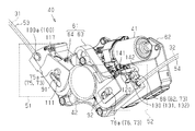
- FIG. 7 is a side view of a drum device with a lid member after a drive cable connection operation and a tension applying device provided in the drum device.
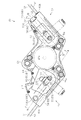
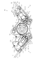
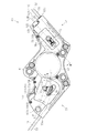
- FIG. 7 is a side view of the drum device without a cover member after the drive cable connection operation and the tension applying device provided in the drum device.
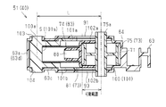
- FIG. 6 is a cross-sectional view of the first tensioning device after the drive cable connection operation, and is a VI-VI cross-sectional view in FIG. 4; FIG.
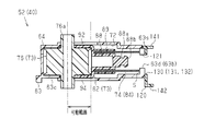
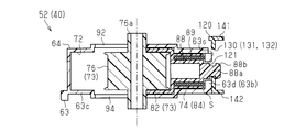
- FIG. 7 is a cross-sectional view of the second tension applying device after the drive cable connection operation, and is a VII-VII cross-sectional view in FIG. 4;
- the disassembled perspective view of a tension provision apparatus The side view of the drum apparatus in a temporary holding state and with a cover member, and the tension provision apparatus provided in the said drum apparatus.
- FIG. 10 is a cross-sectional view of the first tension applying device in the temporarily held state, and is a cross-sectional view taken along line XI-XI in FIG.
- FIG. 9 is a cross-sectional view of the second tension applying device in the temporarily held state, which is a cross-sectional view taken along line XIII-XIII in FIG. 9.
- (A) and (b) are perspective views of a 2nd tension provision apparatus, (a) is a temporary holding state, (b) shows the state after drive cable connection work.
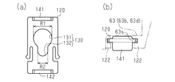
- (A) is a front view of a locking member, (b) is a top view of a locking member. The side view of the axial part provided in the supporting member.
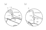
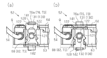
- (A) (b) is operation
- the vehicle 1 of the present embodiment includes a slide door device 30 as a vehicle opening / closing body drive device.
- the vehicle 1 includes a slide door 4 capable of opening and closing the door opening 3 provided on the side surface of the vehicle body 2 by moving in the vehicle longitudinal direction (left and right direction in FIG. 1).
- the slide door 4 corresponds to the opening and closing body.
- the side surfaces of the vehicle body 2 are provided with a plurality of guide rails 11 to 13 extending in the front-rear direction.
- the guide rails (11 to 13) are provided with a center rail 11, an upper rail 12 and a lower rail 13 provided on the rear, upper and lower edges (left side, upper side and lower side in FIG. 1) of the door opening 3.
- the slide door 4 is connected to the guide rails 11 to 13 via the guide roller units 21 to 23.
- Each of the guide roller units 21-23 has a guide roller (not shown) that rolls on a track formed by the corresponding guide rails 11-13.
- the guide roller units 21 to 23 support the slide door 4 on the vehicle body 2 (specifically, the guide rails 11 to 13), and can open and close the slide door 4 moving back and forth along the guide rails 11 to 13. Do.
- the slide door 4, the guide rails 11 to 13 and the guide roller units 21 to 23 form a slide door device 30.
- the slide door device 30 of the present embodiment in the slide door device 30 of the present embodiment, the two drive cables 31 and 32 arranged along the extension direction of the center rail 11 and the drive of the two. And a drum device 40 configured to wind one of the cables 31 and 32 while winding the other. Further, in the present embodiment, the terminals of the drive cables 31 and 32 are connected to the guide roller unit 21 from mutually opposite directions. And thereby, the slide door apparatus 30 of this embodiment is configured to selectively pull the slide door 4 supported by the guide roller unit 21 in the opening direction and the closing direction.
- the drum device 40 of the present embodiment includes a drum 42 that rotates using a motor 41 as a drive source. That is, the proximal ends of the drive cables 31 and 32 are connected to the drum 42.
- the drum device 40 is configured to feed one of the drive cables 31 and 32 and wind the other based on the rotation direction of the drum 42.
- the drum device 40 of the present embodiment includes tension applying devices 51 and 52 configured to apply tension to the drive cables 31 and 32, respectively.
- tension applying devices 51 and 52 By operating the tension applying devices 51 and 52, it is possible to pull the slide door 4 more smoothly by absorbing slack generated when the drive cables 31 and 32 are delivered.
- the drum device 40 is disposed in the vehicle body 2 in the vicinity of the center rail 11, specifically, in a substantially central portion in the longitudinal direction of the center rail 11. Further, two guide tubes 53 and 54 extending toward the vehicle front side and the rear side are connected to the drum device 40.
- the drive cables 31 and 32 are respectively near the front end 11 f (near the end on the right side in FIG. 3) and near the rear end 11 r (in FIG. 3) of the center rail 11 via the guide tubes 53 and 54. It is designed to be pulled out near the left end).
- pulleys 55 and 56 are provided in the vicinity of the front end 11 f and the rear end 11 r of the center rail 11, respectively.
- the drive cables 31 and 32 are respectively routed along the extending direction of the center rail 11 by being wound around the pulleys 55 and 56.
- the first drive cable 31 drawn toward the front end 11 f of the center rail 11 through the guide tube 53 is wound around a pulley 55 provided in the vicinity of the first drive cable 31 so that It is wired from the front end 11 f to the rear end 11 r along the extending direction.
- the second drive cable 32 drawn toward the rear end 11 r of the center rail 11 via the guide tube 54 is wound around a pulley 56 provided in the vicinity of the second drive cable 32 to extend the center rail 11. It is wired from the rear end 11r toward the front end 11f along the direction.
- the guide roller unit 21 pulled by the first drive cable 31 is pulled by the first drive cable 31 by winding the first drive cable 31 by the operation of the drum device 40. Move toward the front end 11f of the Further, by the second drive cable 32 being wound up, the guide roller unit 21 pulled by the second drive cable 32 moves toward the rear end 11 r of the center rail 11. And thereby, the slide door apparatus 30 of this embodiment can make the slide door 4 supported by the guide roller unit 21 open and close.
- the slide door 4 of the present embodiment moves to the front side of the vehicle relative to the side surface of the vehicle body 2 provided with the center rail 11
- the design surface is arranged to be substantially flush.
- the slide door 4 is opened and closed by curving the vehicle front side (right side in FIG. 5) of the guide rails 11 to 13 inward in the vehicle width direction (upper side in FIG. 3). The operation is secured.
- the slide door apparatus 30 of this embodiment can maintain the state in which the slide door 4 is arrange
- the drum device 40 includes a drum accommodating portion 61 in which the drum 42 is accommodated and components such as a speed reducer and a control board for decelerating the rotation of the motor 41. And a motor drive unit 62 in which is accommodated.
- the tension applying devices 51 and 52 of the present embodiment are provided integrally with the drum accommodating portion 61.
- the drum storage portion 61 of the present embodiment includes a bottomed substantially flat box-like housing 63 and a lid member 64 covering the opening of the housing 63.
- the housing 63 of the present embodiment has a substantially W-shaped outer shape in a side view as viewed from the side of the lid member 64 attached to the opening thereof.
- the drum 42 is housed in a central housing portion 70 provided at a substantially central portion of the W shape.
- the drum 42 of the present embodiment is housed in the central housing portion 70 with the rotation shaft 42 a thereof substantially orthogonal to the bottom wall 63 c of the housing 63 and the lid member 64.
- the drum storage portion 61 of the present embodiment is provided with a first storage portion 71 and a second storage portion provided at a position sandwiching the central storage portion 70 in the radial direction of the drum 42 stored in the central storage portion 70. It has 72.
- each of the guide tubes 53 and 54 is connected to the tip portions 63a and 63b of the substantially W-shaped housing 63, respectively.
- the drive cables 31 and 32 are disposed in the first housing portion 71 and the second housing portion 72 communicating with the inserted guide tubes 53 and 54, respectively. It is adapted to be taken up by a drum 42 housed inside.
- each tension applying device 51, 52 of the present embodiment is pressed against the corresponding drive cable 31, 32 to tension the respective drive cable 31, 32.
- a biasing member 74 configured to generate a biasing force that presses the tension applying member 73 against the drive cables 31 and 32.
- the tension applying member 73 of the present embodiment includes the pulleys 75 and 76 pressed against the drive cables 31 and 32, and the support members 81 and 82 rotatably supporting the pulleys 75 and 76, respectively. And is configured. Further, as the biasing member 74, coil springs (compression coil springs) 83 and 84 that generate a biasing force corresponding to the amount of elastic deformation are used. In the drum device 40 of the present embodiment, the pulleys 75 and 76 and the support members 81 and 82 constituting the tension applying member 73, and the coil springs 83 and 84 as the biasing member 74 respectively have their tensions.
- the drive cables 31 and 32 to be applied are accommodated in the first accommodation portion 71 and the second accommodation portion 72 in which the drive cables 31 and 32 are provided.
- each of the support members 81 and 82 of the present embodiment has a pair of side wall portions 86a and 86b having U-shaped grooves 85 at their tips and facing each other, and the base end sides of the side wall portions 86a and 86b. And an axial portion 88 extending in a direction substantially orthogonal to the base wall portion 87.
- the support members 81 and 82 of the present embodiment respectively have the rotation shafts 75a and 76a on both side wall portions 86a. , 86b, and rotatably supports the pulleys 75, 76, respectively.
- the corresponding coil springs 83 and 84 are inserted into the shaft-like portions 88 of the support members 81 and 82, respectively.
- the support member 82 on the side of the second tension applying device 52 for applying tension to the second drive cable 32 has a cylindrical portion 89 surrounding the outside of the coil spring 84 inserted in the axial portion 88. doing.
- each of the coil springs 83 and 84 inserted in the shaft-like portion 88 abuts on the base wall portion 87 of each of the support members 81 and 82.
- the biasing forces generated in the coil springs 83 and 84 are transmitted to the support members 81 and 82 and the pulleys 75 and 76 supported by the support members 81 and 82.
- each coil spring 83, 84 is provided in the first housing portion 71 and the second housing portion 72 formed by the housing 63 and the cover member 64 as the housing members.
- An abutting surface S is formed with which the other end (second end) abuts. That is, each coil spring 83, 84 is compressed between the contact surface S and each support member 81, 82. Then, based on the elastic restoring force, it is possible to bias the pulleys 75 and 76 supported by the respective support members 81 and 82 to press them against the respective drive cables 31 and 32.
- the contact surfaces S are the tips of the housing 63 to which the ends 53e and 54e of the guide tubes 53 and 54 are connected, respectively. It is provided in the vicinity of the parts 63a and 63b.
- the lid member 64 forming the first housing portion 71 and the second housing portion 72 by being attached to the housing 63 has the center from the tip portions 63a and 63b along the W shape of the housing 63 (see FIG. Guide grooves 91 and 92 extending toward the right side in FIG.
- the bottom wall 63c of the housing 63 facing the lid member 64 also has a tip end portion of the housing 63 similar to the guide grooves 91 and 92 at positions facing the guide grooves 91 and 92 near the lid member 64, respectively.
- Guide grooves 93 and 94 extending from the center 63a and 63b toward the center are formed.
- the rotary shafts 75a and 76a of the pulleys 75 and 76 are inserted into the guide grooves 91 and 92 and the guide grooves 93 and 94, respectively.
- the pulleys 75 and 76 are configured to move along the extending direction by being guided by the guide grooves 91 and 92 and the guide grooves 93 and 94.
- the pulleys 75 and 76 urged by the coil springs 83 and 84 are guided by the guide grooves 91 and 92 and the guide grooves 93 and 94, respectively.
- the drive cables 31 and 32 are wound on the drum 42 from the guide tubes 53 and 54 connected to the end portions 63 a and 63 b of the housing 63 and drawn out from the drum 42 toward the guide tubes 53 and 54. Extends in a direction intersecting the guide grooves 91 and 92 and the guide grooves 93 and 94.
- each pulley 75, 76 which constitutes the tension grant member 73 pushes to each drive cable 31, 32 by which wiring was carried out in the 1st seat part 71 and the 2nd seat part 72 by this. It is supposed to be applied.
- the pulleys (75, 76) pressed against the drive cables (31, 32) delivered from the drum 42 move more to the center based on the biasing force of the coil springs (83, 84).
- the pulleys (75, 76) pressed against the drive cables (31, 32) wound around the drum 42 resist the biasing force of the coil springs (83, 84) and end portions (63a, Move towards 63 b).
- each tension application device 51, 52 of this embodiment can apply an appropriate tension to each drive cable 31, 32.
- the tension applying devices 51 and 52 each act as the tension applying member 73 in a state where the force pressed against the drive cables 31 and 32 is weakened.
- the temporary holding structure capable of holding the pulleys 75 and 76 and the support members 81 and 82 is provided. And in this embodiment, when each drive cable 31 and 32 is connected to slide door 4 (guide roller unit 21) by this, the slack amount of each drive cable 31 and 32 is increased, and its connection work is easily carried out. It is possible to do
- the first tension applying device 51 in the present embodiment has a pivot shaft 100a substantially parallel to the pivot shaft 42a of the drum 42.
- a holding member 100 housed in the first housing portion 71 is provided.
- the pulley 75 and the support member 81 constituting the tension applying member 73 of the first tension applying device 51 and the coil spring 83 as the biasing member 74 are held by the holding member 100.
- the holding member 100 of the present embodiment is provided with a rectangular tube portion 101 having an open end (end portion on the right side in FIGS. 6 and 11) and formed in an elongated substantially rectangular tube shape. .
- the pulley 75, the support member 81 and the coil spring 83 are held in the cylinder of the rectangular cylinder portion 101.
- the coil spring 83 is inserted into the rectangular tube portion 101 such that the bottom surface 101 s of the rectangular tube portion 101 is the contact surface S.
- the opposite side wall portions 101a and 101b are cut away from the opening end side to the base end side (from the right side to the left side in FIGS. 6 and 11), A pair of slits 102 a and 102 b extending in the longitudinal direction of the cylindrical portion 101 is formed.
- the pulley 75 and the support member 81 are also inserted into the rectangular tube portion 101 in a state in which the rotation shaft 75a of the pulley 75 is inserted into both the slits 102a and 102b.
- the pivot shaft 100 a of the holding member 100 is provided on the proximal end side of the rectangular tube portion 101. Furthermore, support holes 103 and 104 into which the pivot shaft 100a is inserted are formed in the lid member 64 and the bottom wall 63c of the housing 63 that constitute the first accommodation portion 71, respectively. In the present embodiment, the support holes 103 and 104 are formed in the vicinity of the position where the end 53 e of the guide tube 53 is connected to the tip portion 63 a of the housing 63.
- the holding member 100 according to the present embodiment is thereby configured to cover the bottom wall 63c of the housing 63 in the same plane as the first drive cable 31 wired in the first housing portion 71 like the holding member 100. And, it is possible to turn around the turning shaft 100 a supported by the lid member 64.
- the holding member 100 of the present embodiment can define the moving direction of the pulley 75 and the support member 81 held in the cylinder of the rectangular cylinder portion 101 by the rectangular cylinder portion 101 functioning as a guide portion. Specifically, it is possible to limit in the longitudinal direction. Further, the holding member 100 is capable of changing the moving direction of the pulley 75 and the support member 81 guided by the angular tube portion 101 by rotating around the rotation shaft 100 a. The first tension applying device 51 in the present embodiment rotates the holding member 100 to support the pulley 75 and the support in a state where the force pressed against the first drive cable 31 is weakened. It is possible to temporarily hold the member 81.
- the holding member 100 of the present embodiment is guided to the rectangular tube portion 101 constituting the guide portion by rotating counterclockwise in each figure.
- the angle (pressing angle) with which the pulley 75 thus pressed is pressed against the first drive cable 31 wired in the first accommodation portion 71 based on the biasing force of the coil spring 83 is configured to be shallow.
- the track of the first drive cable 31 drawn out from the drum 42 and taken up by the drum 42 is largely bent as the pressing angle of the pulley 75 against the first drive cable 31 becomes deeper.
- the pressing angle becomes shallower it becomes linear. Therefore, the force with which the pulley 75 is pressed against the first drive cable 31 becomes stronger as the pressing angle changes depending on the rotational position of the holding member 100 and becomes weaker as the pressing angle becomes shallower.
- the first tension applying device 51 in the present embodiment can hold the holding member 100 at the position where the holding member 100 is rotated in the direction in which the pressing angle of the pulley 75 becomes shallow. There is.
- the lid member 64 forming the first accommodation portion 71 and the bottom wall 63 c of the housing 63 respectively intersect the first guide grooves 91 and 93.
- the second guide grooves 111 and 113 are formed to extend. And in this embodiment, these 2nd guide grooves 111 and 113 also serve as a hole which can penetrate axis of rotation 75a of pulley 75.
- the pulley 75 moves in the direction away from the first drive cable 31 against the biasing force of the coil spring 83 to move to the first guide groove 91, 93.
- the inserted rotary shaft 75 a is movable from the first guide groove 91, 93 to the second guide groove 111, 113.
- the first tension applying device 51 in the present embodiment is guided by the second guide grooves 111 and 113, and the pulley 75 and the support member 81 move in the extending direction of the second guide grooves 111 and 113.
- the rotation of the holding member 100 is permitted.
- the holding member 100 is directed in a direction (counterclockwise direction in FIG. 9) in which the rotation shaft 75a of the pulley 75 guided by the second guide grooves 111 and 113 is separated from the first guide grooves 91 and 93.
- the first tension applying device 51 in the present embodiment can thereby hold the pulley 75 and the support member 81 at a position where the force pressed against the first drive cable 31 is weakened. ing.
- the pulleys 75 guided by the second guide grooves 111 and 113 are used as the first guide grooves 91, 91 when the holding member 100 rotates.
- the coil spring 83 held by the holding member 100 has a shape capable of accumulating the biasing force.
- the second guide grooves 111 and 113 move in a direction in which the pulley 75 moves away from the first guide grooves 91 and 93, thereby rotating the rotation shaft 75 a of the pulley 75 and the rotation of the holding member 100.
- the inter-core distance (L, L ') to the moving shaft 100a is configured to be short (L> L'). See FIG. 6 and FIG. And, in the present embodiment, thereby, the coil spring 83 is compressed between the support member 81 of the pulley 75 and the contact surface S formed on the holding member 100.
- the second guide grooves 111 and 113 are separated from the most first guide grooves 91 and 93, that is, the holding member 100 shown in FIG.
- a locking portion 115 capable of locking the rotation shaft 75a of the pulley 75 guided to the second guide grooves 111 and 113 is provided.
- the locking portion 115 is formed by bending the extending direction of the second guide grooves 111 and 113.
- the rotary shaft 75a of the pulley 75 is locked at a position separated most from the first guide grooves 91, 93. It has become.
- the first tension applying device 51 in the present embodiment is shown in a rotational position where the rotary shaft 75a of the pulley 75 is inserted into the first guide grooves 91 and 93, ie, as shown in FIGS.
- a rotation restricting member 117 capable of restricting the rotation of the holding member 100 is provided.
- the rotation restricting member 117 of this embodiment is integrated with the holding member 100 in such a manner that the tip end thereof protrudes toward the peripheral wall 63d of the housing 63. It is provided. Further, in the present embodiment, on the circumferential wall 63 d of the housing 63, an engagement convex portion 118 that protrudes toward the inside of the first accommodation portion 71 is formed. Further, at the tip end portion of the rotation restricting member 117, an engagement concave portion 119 which can be engaged with the engagement convex portion 118 is provided.
- the rotation restricting member 117 of the present embodiment rotates the holding shaft 100 integrally with the holding member 100 so that the rotation shaft 75 a of the pulley 75 is guided to the first guide grooves 91 and 93.
- the engagement recess 119 is configured to engage with the engagement projection 118 formed on the peripheral wall 63 d of the housing 63. See FIG. 4 and FIG.
- the first tension application device 51 in the present embodiment regulates the rotation of the holding member 100 by this, so that the pulley 75 guided to the first guide groove 91, 93 can stably be It is configured to be movable in the pressing direction and the separating direction with respect to the first drive cable 31.
- the pulley 76 and the support member 82 accommodated in the second accommodation portion 72 are the lid member 64 and the housing. It is guided by the guide grooves 92, 94 formed in the bottom wall 63c of 63. Thereby, it is possible to move in the pressing direction and the separating direction with respect to the second drive cable 32.
- the second tension applying device 52 has a position at which the pulley 76 and the support member 82 constituting the tension applying member 73 move in the direction away from the second drive cable 32, that is, the biasing member 74. At a position where the biasing force of the coil spring 84 is accumulated in the coil spring 84, a locking member 120 capable of locking the pulley 76 and the support member 82 to the housing 63 is provided.
- the housing 63 is located at the tip portion 63b on the second accommodation portion 72 side to which the end 54e of the guide tube 54 is connected.
- the peripheral wall 63d is formed with a through hole 121 through which the shaft-like portion 88 is inserted.
- the locking member 120 of the present embodiment is provided on the outer peripheral surface 63s of the housing 63 at the position where the through hole 121 is formed.
- the support member 82 and the pulley 76 can be locked to the housing 63 by engaging with the shaft-like portion 88 of the support member 82 protruding toward the outer peripheral surface 63s of the housing 63 through the through hole 121. It has become.
- the locking member 120 of this embodiment has a substantially rectangular flat outer shape.
- a pair of guide flanges 122 for holding the locking member 120 in a slidable manner sandwiching the locking member 120 with the outer peripheral surface 63s is provided on the outer peripheral surface 63s of the housing 63.
- the guide flange 122 sandwiches the locking member 120 in the lateral direction (in the left and right direction in FIG. 15A), so that the through hole 121 is formed in the locking member 120. Hold in place.
- the locking member 120 of the present embodiment is configured such that the longitudinal direction (vertical direction in FIG. 15A) substantially coincides with the axial direction (the extending direction of the rotation shaft 76a) of the pulley 76. It is possible to slide on the outer peripheral surface 63s of the housing 63 along the longitudinal direction.
- operation flanges 141 and 142 projecting in the plate thickness direction (vertical direction in FIG. 15B) of the locking member 120 are provided at both ends in the longitudinal direction of the locking member 120.
- an insertion hole 130 which penetrates the locking member 120 in the thickness direction is formed.
- the shaft-like portion 88 of the support member 82 protruding toward the outer peripheral surface 63s of the housing 63 through the through hole 121 is inserted into the insertion hole 130.
- the insertion hole 130 has first and second hole portions 131 and 132 continuous in the longitudinal direction of the locking member 120.
- the first hole portion 131 has a shape that allows insertion / removal of the shaft-like portion 88 in the direction in which the support member 82 biased by the coil spring 84 moves, that is, in the thickness direction of the locking member 120.
- the second hole 132 engages with the shaft-like portion 88 inserted in the second hole 132 to form a shaft in the direction in which the support member 82 biased by the coil spring 84 moves. It has a shape capable of restricting the removal of the portion 88.
- the shaft-like portion 88 that constitutes the engagement protrusion is a substantially cylindrical small diameter portion 88 a and a tip of the small diameter portion 88 a. And a flange portion 88b provided.
- the 1st and 2nd hole 131,132 has a circular hole shape which mutually overlaps partially in the longitudinal direction of the locking member 120, respectively.
- the inner diameter R1 of the first hole portion 131 is set to a value larger than the diameter D2 of the flange portion 88b of the shaft-like portion 88 (R1> D2).
- the inner diameter R2 of the second hole 132 is larger than the diameter D1 of the small diameter portion 88a of the shaft 88 and smaller than the diameter D2 of the flange 88b (D1 ⁇ R2 ⁇ D2).
- the locking member 120 of the present embodiment slides in the longitudinal direction when the operation flanges 141 and 142 are operated. And thereby, either of the 1st and 2nd hole parts 131 and 132 which constitute the penetration hole 130 is arranged in the position corresponding to the above-mentioned penetration hole 121.
- the shaft-like portion 88 of the support member 82 inserted into the insertion hole 130 is relatively relatively It is configured to move between the first and second holes 131 and 132.
- the second tension applying device 52 in the present embodiment thereby locks the pulley 76 and the support member 82 at a position where the biasing force of the coil spring 84 is accumulated in the coil spring 84, and releases the lock. It is possible to
- the locking member 120 of the present embodiment is a side view as viewed from the outer peripheral surface 63s of the housing 63 in which the locking member 120 is held.
- the housing 63 and the contour Q of the lid member 64 one of the longitudinal end portions is projected. That is, when one of the operation flanges 141 and 142 provided at both ends in the longitudinal direction of the locking member 120 of the present embodiment is embedded inside the contour Q of the housing 63 and the lid member 64, the other is embedded. It projects from the contour Q of the housing 63 and the lid member 64 in the direction.
- the locking member 120 is thus configured to be operated in the direction in which the operation flanges 141 and 142 on the protruding side thereof are inserted into the inside of the contour Q of the housing 63 and the lid member 64.
- the operation flange 141 as the first operation portion is on the lid member 64 side ( In the case of projecting upward in FIG. 13 and FIG. 17A, the second hole 132 is arranged at a position corresponding to the through hole 121.
- the operation flange 142 as a 2nd operation part of the locking member 120 of this embodiment is the bottom wall 63c side of the housing 63 ( When projecting downward in FIG. 7 and FIG. 17 (b), the first hole portion 131 is arranged at a position corresponding to the through hole 121.
- the shaft-like portion 88 of the support member 82 can be inserted into the insertion hole 130 in the first hole portion 131.
- the support member 82 and the pulley 76 can be moved to a position where the biasing force is accumulated in the coil spring 84.
- the operation flange 141 is pressed inside the contour Q of the housing 63 and the cover member 64 by pressing the operation flange 141.
- the locking member 120 By operating the locking member 120 in the retracting direction, the locking of the support member 82 and the pulley 76 is released.
- the second tension applying device 52 in this embodiment is configured to move in such a direction that the support member 82 biased by the coil spring 84 and the pulley 76 are pressed against the second drive cable 32. It has become.
- the second guide groove 111 extends such that the rotation shaft 75a of the pulley 75 that constitutes the tension application member 73 intersects the first guide grooves 91 and 93. , 113, ie, engaged.
- the support member 82 of the pulley 76 which similarly constitutes the tension applying member 73, and more specifically, the shaft-like portion 88 of the support member 82 is accommodated by the locking member 120 as its housing member.
- connection work of the drive cables 31 and 32 to the slide door 4 is performed in a state where the tension applying members 73 of the tension applying devices 51 and 52 are temporarily held in this manner. Then, after the connection work, by releasing the biasing force accumulated in each coil spring 83, 84, appropriate tension is applied to each drive cable 31, 32 to which each pulley 75, 76 is pressed. It has become.
- the rotation shaft of the pulley 75 which protrudes from the lid member 64 (the bottom wall 63c of the housing 63) by being inserted into the second guide groove 111 (113).
- the rotary shaft 75a is moved from the second guide grooves 111 and 113 to the first guide grooves 91 and 93 by operating the 75a.
- the pressing angle of the pulley 75 with respect to the first drive cable 31 becomes deeper.
- the rotation restricting member 117 restricts the rotation of the holding member 100 in this state.
- the first tension applying device 51 in the present embodiment is configured such that the pulley 75 and the support member 81 urged by the coil spring 83 are guided by the first guide grooves 91 and 93.
- the drive cable 31 is configured to be movable in the pressing direction and the separating direction.
- the locking member is pressed in a direction in which the operating flange 141 as the operating portion is pressed to immerse the operating flange 141 inside the contour Q of the housing 63 and the lid member 64. Operate 120. Then, in the second tension applying device 52 in the present embodiment, the locking of the support member 82 by the locking member 120 is released.
- the second drive cable 32 can move in the pressing direction and the separating direction. It is configured.
- the first tension applying device 51 includes the holding member 100 having a guide portion for defining the moving direction of the tension applying member 73 biased by the biasing member 74, and the tension applying member 73 and the retaining member inside A housing 63 as a housing member for housing 100 and a lid member 64 are provided.
- the holding member 100 is configured to be able to change the moving direction of the tension applying member 73 guided by the guide portion by being accommodated in the first accommodation portion 71 with the rotation shaft 100 a.
- the housing 63 and the lid member 64 can temporarily hold the holding member 100 at a position where the holding member 100 is rotated in the direction in which the pressing angle of the tension applying member 73 against the first drive cable 31 becomes shallow.
- a retention structure is formed.
- the force with which the tension applying member 73 is pressed against the first drive cable 31 becomes stronger as the pressing angle changing due to the rotation of the holding member 100 becomes deeper, and becomes weaker as the pressing angle becomes shallower. Therefore, according to the above configuration, the direction (pressing direction) pressed against the first drive cable 31 based on the biasing force of the biasing member 74 and the direction away from the first drive cable 31 against the biasing force.
- the pressing force can be weakened to secure a large amount of slack without increasing the stroke amount of the tension applying member 73 in the (separation direction). And thereby, the connection operation of the 1st drive cable 31 can be facilitated, without preventing the tension application and the miniaturization of a device appropriately. Further, when the holding member 100 is rotated to release the temporary holding state, there is an advantage that the biasing member 74 does not become a resistance. And thereby, the outstanding operativity can be ensured.
- the second tension applying device 52 includes the locking member 120 capable of locking the tension applying member 73 to the housing 63 as a housing member at a position where the biasing force is accumulated in the biasing member 74. Further, the locking member 120 has an operation flange 141 as an operation portion that protrudes from the contour Q of the housing 63 and the lid member 64. The locking member 120 is configured to be able to release the locking of the tension applying member 73 by being operated in the direction in which the operation flange 141 is inserted into the inside of the contour Q of the housing 63 and the lid member 64. .
- the locking member 120 can be operated easily and reliably. And thereby, the outstanding operativity can be ensured.
- the tension applying member 73 includes pulleys 75 and 76 pressed against the drive cables 31 and 32, and a support member 81 rotatably supporting the pulleys 75 and 76, And 82. As a result, tension can be applied to the drive cables 31 and 32 on which the tension applying member 73 is pressed, stably and reliably, without interfering with the operation of the drive cables 31 and 32.
- the locking member 120 is operated as a second operating portion which protrudes from the contour Q in a direction in which the operating flange 141 as the first operating portion is inserted into the inside of the contour Q of the housing 63 and the lid member 64. It has a flange 142. Then, by operating the operation flange 142 in the direction of immersing the inside of the contour Q of the housing 63 and the lid member 64, the tension applying member 73 can be locked to the housing 63 at a position where the biasing force is accumulated.
- the locking operation of the tension applying member 73 with respect to the housing 63 can be performed by a simple operation that can be intuitively understood. And thereby, more excellent operability can be secured.
- One of the operation flanges 141 and 142 of the locking member 120 is inserted into the inside of the contour Q of the housing 63 and the lid member 64, and the other is a contour of the housing 63 and the lid member 64 in the immersion direction. It is configured to protrude from Q.
- the locking member 120 is provided with the insertion hole 130 having the first and second holes 131 and 132 continuous in the operating direction of the locking member 120. Further, the support member 82 which constitutes the tension applying member 73 together with the pulley 76 is an engagement protrusion which is inserted into the insertion hole 130 of the locking member 120 at a position where the support member 82 is locked to the housing 63.
- the shaft-like portion 88 is provided. Furthermore, the first hole portion 131 has a shape that allows insertion and removal of the shaft-like portion 88 in the direction in which the support member 82 biased by the coil spring 84 moves.
- the second hole portion 132 has a shape capable of restricting removal of the shaft-like portion 88 in a direction in which the support member 82 biased by the coil spring 84 moves by engaging with the shaft-like portion 88. Then, in the insertion hole 130, when the locking member 120 is operated, the shaft-like portion 88 inserted into the insertion hole 130 relatively moves between the first and second hole portions 131 and 132. Configured as.
- the tension applying member 73 can be locked to the housing 63 by operating the operation flange 142 as the second operation portion in the retraction direction with a simple configuration, and as the first operation portion By operating the operation flange 141 in the retraction direction, the locking member 120 capable of releasing the locking of the tension applying member 73 can be formed.
- the peripheral wall 63d of the housing 63 is configured to be a wall having a through hole 121 through which the shaft-like portion 88 provided in the support member 82 is inserted at a position where the biasing force is accumulated in the coil spring 84. Ru.
- the locking member 120 slides on the wall surface of the wall portion facing the opposite side of the tension applying member 73, that is, the outer peripheral surface 63s of the housing 63. It is configured to be detachable with respect to 88.
- the tension applying member 73 can be reliably locked to the housing 63 by the locking member 120 with a simple configuration, and the locking can be released.
- the biasing member 74 is compressed between the contact surfaces S formed in the first housing portion 71 and the second housing portion 72 and the support members 81 and 82, respectively.
- the coil springs 83 and 84 which generate the energizing force according to the amount of elastic deformation are used.
- each tension applying member 73 it is possible to bias each tension applying member 73 to press the drive cables 31 and 32 stably and reliably. And thereby, there exists an advantage that the biasing member 74 can be arrange
- a first guide capable of guiding the tension applying member 73 biased by the biasing member 74 in the pressing direction and the separating direction of the first drive cable 31 to the housing 63 and the lid member 64 as the housing members. Grooves 91 and 93 are provided. Further, the housing 63 and the lid member 64 further extend in such a manner as to cross the first guide grooves 91 and 93 to thereby allow rotation of the holding member 100. Is provided.
- the holding member 100 can be stably rotated. Then, by rotating the holding member 100 in the direction in which the tension applying member 73 separates from the first guide grooves 91 and 93, the pressing angle of the tension applying member 73 on the first drive cable 31 is made shallow. Can. Further, by rotating the holding member 100 in the reverse direction from this state, the tension applying member 73 can be returned to the state of being guided by the first guide grooves 91 and 93. Thus, appropriate tension can be applied to the first drive cable 31 to which the tension applying member 73 is pressed.
- the second guide groove 111, 113 engages the tension applying member 73 with the second guide groove 111, 113 at the rotational position of the holding member 100 where the pressing angle of the tension applying member 73 becomes shallow.
- a locking part 115 which can be stopped is provided.
- the holding member 100 can be stably held at the rotational position where the pressing angle of the tension applying member 73 is shallow.
- the first tension applying device 51 is capable of restricting the rotation of the holding member 100 at the rotational position where the tension applying member 73 is guided by the first guide grooves 91 and 93.
- a regulating member 117 is provided.
- the rotary shaft 75a of the pulley 75 inserted in the first guide grooves 91, 93 and the second guide grooves 111, 113 is a housing 63 as a housing member and a lid member It is configured to protrude outside of 64. With such a configuration, the holding member 100 can be easily rotated by operating the rotation shaft 75 a of the pulley 75 projecting to the outside of the housing 63 and the lid member 64.
- the contact surface S of the coil spring 83 is provided on the holding member 100.
- the drum device 40 includes the first and second tension applying devices 51 and 52 having different temporary holding structures of the tension applying members 73.
- the first tension applying device 51 applies tension to the first drive cable 31, and the second tension applying device 52 applies tension to the second drive cable 32.
- the tension applying device 51 provided with the rotatable holding member 100 may apply tension to both the first and second drive cables 31 and 32.
- the tension applying device 52 provided with the locking member 120 for applying the tension may be applied.
- the tension applying devices 51 and 52 do not necessarily have to be provided integrally with the drum device 40. And tension may be given to drive cables used for open-close body drive devices other than slide door device 30.
- coil springs (compression coil springs) 83 and 84 are used as the biasing member 74.
- the invention is not limited to this.
- other spring members such as a torsion coil spring or a plate spring, or an urging member other than the spring member may be used.
- the tension applying member 73 includes the pulleys 75 and 76 pressed against the drive cables 31 and 32, and the support members 81 and 82 rotatably supporting the pulleys 75 and 76.
- the present invention is not limited to this, and for example, a non-rotating body having a sliding contact surface pressed against each of the drive cables 31 and 32 may be used as the tension applying member.
- the first tension applying device 51 may be configured to directly bias the rotation shaft 75 a of the pulley 75 without the support member 81.
- the drum accommodating portion 61 is configured by assembling the lid member 64 to the housing 63.
- the configuration of the housing member may be arbitrarily changed.
- the biasing member 74 may not necessarily be housed in the housing member.
- the holding member 100 includes the rectangular cylindrical portion 101 having an open end and formed in a long rectangular cylinder shape, and the pulley 75, the support member 81, and the coil spring 83 are formed in the rectangular cylindrical portion 101.
- the configuration of the holding member 100 including the guide portion may be arbitrarily changed. And also about the formation position of the rotational axis 100a, it does not necessarily restrict to the base end side of the rectangular tube part 101.
- the first tension applying device 51 includes the rotation restricting member 117 capable of restricting the rotation of the holding member 100.
- the rotation restricting member 117 is at a rotation position where the rotation shaft 75a of the pulley 75 is inserted into the first guide grooves 91 and 93, that is, the pulley 75 biased by the coil spring 83 is At the rotational position where tension is to be applied to the drive cable 31 of 1, the rotation of the holding member 100 can be restricted.
- the present invention is not limited to this, and the configuration may be such that the rotation of the holding member 100 can be restricted at the rotational position where the pressing angle of the pulley 75 with respect to the first drive cable 31 becomes shallow.
- the structure which is not equipped with such a holding member 100 may be sufficient.
- the second guide grooves 111 and 113 bias the coil spring 83 held by the holding member 100 by moving the pulley 75 in the direction in which the pulley 75 separates from the first guide grooves 91 and 93. It was decided to have a shape capable of accumulating However, the configuration is not limited thereto, and the biasing force of the coil spring 83 may not be changed by the movement of the tension applying member 73 guided to the second guide grooves 111 and 113. Then, the coil spring 83 may have a shape capable of accumulating the biasing force by moving the pulley 75 in the direction approaching the first guide grooves 91 and 93. By employing such a configuration, when temporarily holding the tension applying member 73, the holding member 100 can be easily rotated by utilizing the biasing force of the biasing member 74.
- the locking portion 115 capable of locking the application member 73 is provided, such a locking portion 115 may not necessarily be provided.
- first guide grooves 91 and 93 and the second guide grooves 111 and 113 may not necessarily be those through which the rotation shaft 75 a of the pulley 75 is inserted. Further, such a configuration in which the first guide grooves 91 and 93 and the second guide grooves 111 and 113 are not formed in the housing member may be adopted. In this case, for example, it is preferable that the rotation restricting member 117 restricts the rotation of the holding member 100 even in the rotation position where the pulley 75 should apply tension to the first drive cable 31. .
- the locking member 120 has a substantially rectangular flat outer shape. Then, at both ends in the longitudinal direction, first and second operation flanges 141 and 142 serving as operation portions are provided. However, the shape of the locking member 120 may be arbitrarily changed.
- the locking member 120 slides on the outer peripheral surface 63s of the housing 63 to protrude to the outer peripheral surface 63s of the housing 63 through the through hole 121 formed in the peripheral wall 63d. It was decided that the shaft-like portion 88 of the support member 82 be engaged and disengaged. However, the invention is not limited to this, and for example, the locking member 120 may be held inside the housing member. The tension applying member 73 may be locked to the lid member 64.
- the locking member 120 is the operation flange 141 as a first operation portion projecting to the lid member 64 side or the operation flange as a second operation portion projecting to the bottom wall 63c side of the housing 63. It was decided to operate by pressing any of 142. However, the operation direction of the locking member 120 may be arbitrarily changed as long as the operation portion is operated in the direction of being embedded inside the outline of the housing member.
- the locking member 120 locks the support member 82 to the housing 63 with the shaft-shaped portion 88 of the support member 82 as the engagement projection.
- the shape of the engaging protrusion is not limited to this, and may be arbitrarily changed. And in this case, it is good also about the penetration hole 130 by the side of locking member 120 to change the shape of the 1st and 2nd holes 131 and 132 according to the shape of the engagement projection.
- the tensioning device wherein the tensioning member comprises a rotatably supported pulley.
- tension can be applied to the drive cable pressed by the tension applying member stably and reliably without interfering with the operation of the drive cable.
- the tension applying device wherein the biasing member is a coil spring that generates a biasing force according to the amount of elastic deformation by being compressed between the contact surface formed in the housing member and the support member. .
- the biasing member can be arrange
- a tension applying member capable of applying tension to the drive cable by pressing the drive cable, an urging member capable of generating an urging force pressing the tension applying member against the drive cable, the tension application
- a holding member having a guide portion for defining a moving direction of the member, and a receiving member for receiving the tension applying member and the holding member, the holding member having a pivot shaft and disposed in the receiving member
- the force with which the tension applying member is pressed against the drive cable is stronger as the pressing angle which changes due to the rotation of the holding member is deeper and as the pressing angle is shallower. Therefore, according to the above configuration, tension is applied in the direction (pressing direction) pressed against the drive cable based on the biasing force of the biasing member and in the direction (away direction) away from the drive cable against the biasing force. A large amount of slack can be secured by reducing the force pressed against the drive cable without increasing the stroke amount of the member. And thereby, the operation of connecting the drive cable can be facilitated without preventing the appropriate tensioning and the downsizing of the device. Further, when the holding member is rotated to release the holding state (temporary holding state), there is an advantage that the biasing member does not become a resistance. And thereby, the outstanding operativity can be ensured.
- the storage member is capable of guiding the tension applying member biased by the biasing member in a pressing direction and a separating direction with respect to the drive cable.
- a tension applying device comprising: a guide groove; and a second guide groove that allows rotation of the holding member by extending in an intersecting manner with the first guide groove.
- the holding member can be stably rotated by setting the tension applying member to be guided by the second guide groove. Then, by rotating the holding member in the direction in which the tension applying member separates from the first guide groove, the pressing angle of the tension applying member with respect to the drive cable can be made shallow. Further, by rotating the holding member in the reverse direction from this state, the tension applying member can be returned to the state of being guided by the first guide groove. And thereby, an appropriate tension can be given to the drive cable to which the tension giving member was pressed.
- the biasing member generates the biasing force according to the amount of elastic deformation
- the second guide groove is the tension applying member guided to the second guide groove.
- a tension applying device having a shape configured to accumulate the biasing force on the biasing member by moving in a direction away from the first guide groove.
- the biasing member generates the biasing force according to the amount of elastic deformation
- the second guide groove is formed by the tension applying member along the second guide groove.
- a tension applying device having a shape configured to accumulate the biasing force on the biasing member by moving in a direction approaching the guide groove of 1.
- the holding member when temporarily retaining the tension applying member, the holding member can be easily rotated by utilizing the biasing force accumulated in the biasing member. And thereby, the outstanding operativity can be ensured.
- the second guide groove is formed with a locking portion capable of locking the tension applying member in the second guide groove at the rotational position of the holding member at which the pressing angle is reduced. , Tensioning device.
- the holding member can be stably held at the rotational position where the pressing angle of the tension applying member is shallow.
- a tension applying device including a rotation regulating member capable of regulating rotation of the holding member.
- the rotation of the holding member can be restricted at the rotational position where the tension applying member should apply tension to the drive cable.
- the tension applying device is configured such that the rotary shaft of the pulley inserted in the first guide groove and the second guide groove protrudes to the outside of the housing member. With such a configuration, the holding member can be easily pivoted by operating the rotary shaft of the pulley projecting out of the housing member.
- the contact surface is provided on the holding member.
Landscapes
- Power-Operated Mechanisms For Wings (AREA)
- Closing And Opening Devices For Wings, And Checks For Wings (AREA)
Abstract
張力付与装置は、駆動ケーブルに押し当てられることにより該駆動ケーブルに張力を付与する張力付与部材と、張力付与部材を駆動ケーブルに押し当てる付勢力を発生する付勢部材と、張力付与部材を収容する収容部材と、付勢力が付勢部材に蓄積される位置において張力付与部材を収容部材に係止する係止部材とを備える。係止部材は、収容部材の輪郭から突出する操作部を有する。該操作部が輪郭の内側に没入する方向に操作されることにより、係止部材は、張力付与部材の係止を解除する。
Description
本発明は、張力付与装置、ドラム装置及び車両用開閉体駆動装置に関するものである。
通常、駆動ケーブルを用いて開閉体を駆動する車両用の開閉体駆動装置には、その駆動ケーブルに張力を付与可能な張力付与装置が設けられている。例えば、特許文献1に記載のスライドドア装置は、そのスライドドアを開方向及び閉方向に牽引する二本の駆動ケーブルを備えている。そして、その張力付与装置は、これら二本の駆動ケーブルの一方を繰り出しつつ他方を巻き取り可能なドラム装置に設けられている。
即ち、このようなドラム装置に張力付与装置を設けることによって、繰り出された駆動ケーブルに発生する弛みを吸収することができる。そして、これにより、そのスライドドアを円滑に牽引することが可能となっている。
具体的には、多くの場合、このような張力付与装置は、バネ部材の弾性復元力に基づき張力付与部材(例えば、プーリー)を付勢して駆動ケーブルに押し当てることにより、その駆動ケーブルに張力を付与する構成となっている。そして、例えば、特許文献2に記載の張力付与装置は、そのバネ部材の付勢力が蓄積される位置において張力付与部材を収容部材に係止可能な係止部材を備えている。
即ち、張力付与部材を収容部材に係止することにより、そのバネ部材に蓄積された付勢力が駆動ケーブルに伝達されなくなる。そして、各駆動ケーブルをスライドドアに接続する際には、これにより駆動ケーブルの弛み量を増やすことで、その接続作業を容易化することができる。
また、この従来例の係止部材には、収容部材の外側に突出した操作部が設けられている。そして、この操作部を操作して係止部材を回動させることにより、その張力付与部材の係止を解除して駆動ケーブルに押し当てることが可能となっている。
しかしながら、通常、収容部材の外側に突出する可動部位は、より小さなものであることが望まれる。そして、上記従来技術では、これにより、その係止解除時における操作性が低下するおそれがあることから、この点において、なお改善の余地を残すものとなっていた。
本発明の目的は、より操作性に優れた張力付与装置、ドラム装置及び車両用開閉体駆動装置を提供することにある。
上記目的を達成する第1の態様は、張力付与装置を提供する。張力付与装置は、駆動ケーブルに押し当てられることにより該駆動ケーブルに張力を付与する張力付与部材と、前記張力付与部材を前記駆動ケーブルに押し当てる付勢力を発生する付勢部材と、前記張力付与部材を収容する収容部材と、前記付勢力が前記付勢部材に蓄積される位置において前記張力付与部材を収容部材に係止する係止部材と、を備える。前記係止部材は、前記収容部材の輪郭から突出する操作部を有する。該操作部が前記輪郭の内側に没入する方向に操作されることにより、前記係止部材は、前記張力付与部材の係止を解除する。
上記目的を達成する第2の態様は、モータと、前記モータを駆動源として回転するドラムと、前記ドラムを収容するドラム収容部と、前記ドラム収容部に設けられた第1の態様の張力付与装置とを備えるドラム装置を提供する。
上記目的を達成する第3の態様は、開閉体と、複数のガイドレールと、前記開閉体と前記ガイドレールとを相互に連結する複数のガイドローラユニットと、第1の態様の張力付与装置とを備えた車両用開閉体駆動装置を提供する。
以下、本発明の一実施形態に係る張力付与装置、ドラム装置及び車両用開閉体駆動装置を図面に従って説明する。
図1に示すように、本実施形態の車両1は、車両用開閉体駆動装置としてのスライドドア装置30を備える。車両1は、車両前後方向(図1中、左右方向)に移動することにより車体2の側面に設けられたドア開口部3を開閉可能なスライドドア4を備えている。スライドドア4は、開閉体に対応する。
図1に示すように、本実施形態の車両1は、車両用開閉体駆動装置としてのスライドドア装置30を備える。車両1は、車両前後方向(図1中、左右方向)に移動することにより車体2の側面に設けられたドア開口部3を開閉可能なスライドドア4を備えている。スライドドア4は、開閉体に対応する。
詳述すると、車体2の側面には、前後方向に延びる複数のガイドレール11~13が設けられている。ガイドレール(11~13)は、ドア開口部3の後方、上縁部及び下縁部(図1中、左側、上側及び下側)にそれぞれ設けられたセンターレール11、アッパレール12及びロアレール13を含む。また、スライドドア4は、ガイドローラユニット21~23を介してガイドレール11~13に連結されている。各ガイドローラユニット21~23は、対応するガイドレール11~13が形成する軌道上を転動するガイドローラー(図示略)を有する。これらのガイドローラユニット21~23は、車体2(詳しくはガイドレール11~13)にスライドドア4を支持して、ガイドレール11~13に沿って前後移動するスライドドア4の開閉動作を可能とする。スライドドア4、ガイドレール11~13及びガイドローラユニット21~23は、スライドドア装置30を形成する。
また、図2及び図3に示すように、本実施形態のスライドドア装置30は、センターレール11の延伸方向に沿って配索された二本の駆動ケーブル31,32と、これら二本の駆動ケーブル31,32の一方を繰り出しつつ他方を巻き取るように構成されたドラム装置40と、を備えている。また、本実施形態では、各駆動ケーブル31,32の端末は、それぞれ、互いに相反する方向から上記ガイドローラユニット21に接続されている。そして、本実施形態のスライドドア装置30は、これにより、そのガイドローラユニット21に支持されたスライドドア4を開方向及び閉方向に選択的に牽引するように構成されている。
さらに詳述すると、図2に示すように、本実施形態のドラム装置40は、モータ41を駆動源として回転するドラム42を備えている。即ち、上記各駆動ケーブル31,32の基端が、このドラム42に接続されている。そして、ドラム装置40は、そのドラム42の回転方向に基づいて、各駆動ケーブル31,32の一方を繰り出し、他方を巻き取るように構成されている。
また、本実施形態のドラム装置40は、駆動ケーブル31,32にそれぞれ張力を付与するように構成された張力付与装置51,52を備える。張力付与装置51,52の動作により、各駆動ケーブル31,32を繰り出す際に生ずる弛みを吸収することで、より円滑に、スライドドア4を牽引することが可能となっている。
図3に示すように、本実施形態の車両1において、ドラム装置40は、センターレール11近傍の車体2内、詳しくは、そのセンターレール11の長手方向略中央部分に配置されている。また、このドラム装置40には、車両前方側及び後方側に向かって延びる二本のガイドチューブ53,54が接続されている。そして、上記各駆動ケーブル31,32は、それぞれ、各ガイドチューブ53,54を介してセンターレール11の前端11f近傍(図3中、右側の端部近傍)及び後端11r近傍(図3中、左側の端部近傍)に引き出されるようになっている。
また、本実施形態では、センターレール11の前端11f及び後端11rの近傍には、それぞれ、プーリー55,56が設けられている。そして、各駆動ケーブル31,32は、これらのプーリー55,56に巻き掛けられることにより、それぞれ、センターレール11の延伸方向に沿って配索されるようになっている。
具体的には、ガイドチューブ53を介してセンターレール11の前端11fに向かって引き出された第1の駆動ケーブル31は、その近傍に設けられたプーリー55に巻き掛けられることにより、センターレール11の延伸方向に沿うようにして前端11fから後端11rに向かって配索されている。そして、ガイドチューブ54を介してセンターレール11の後端11rに向かって引き出された第2の駆動ケーブル32は、その近傍に設けられたプーリー56に巻き掛けられることにより、そのセンターレール11の延伸方向に沿うようにして後端11rから前端11fに向かって配索されている。
即ち、本実施形態のスライドドア装置30は、ドラム装置40の作動によって、第1の駆動ケーブル31が巻き取られることにより、第1の駆動ケーブル31に牽引されたガイドローラユニット21がセンターレール11の前端11fに向かって移動する。また、第2の駆動ケーブル32が巻き取られることにより、第2の駆動ケーブル32に牽引されたガイドローラユニット21がセンターレール11の後端11rに向かって移動する。そして、本実施形態のスライドドア装置30は、これにより、そのガイドローラユニット21に支持されたスライドドア4を開閉動作させることが可能となっている。
尚、本実施形態のスライドドア4は、車両前方側に移動した全閉位置(図3中、二点鎖線に示す位置)においては、そのセンターレール11が設けられた車体2の側面に対して意匠面が略面一となるように配置される。また、その開動作により車両後方側(図3中、左側)に移動した場合には、車体の側面に干渉しないように、その車体2の側面よりも車幅方向車外側(図3中、下側)に配置される。そして、本実施形態では、各ガイドレール11~13の車両前方側(図5中、右側)を車幅方向内側(図3中、上側)に向かって湾曲させることで、このスライドドア4の開閉動作が担保されている。
また、本実施形態では、このようにガイドレール11~13に設定された湾曲部分をガイドローラユニット21が通過する際、回動軸60周りに当該ガイドローラユニット21が相対回動するようになっている。そして、本実施形態のスライドドア装置30は、これにより、その動作位置に関わらず、スライドドア4が車体2の側面に対して略平行に配置された状態を維持することが可能となっている。
(張力付与装置)
次に、本実施形態のドラム装置40に設けられた張力付与装置51,52の構成について説明する。
次に、本実施形態のドラム装置40に設けられた張力付与装置51,52の構成について説明する。
図2及び図3に示すように、本実施形態のドラム装置40は、内側にドラム42が収容されたドラム収容部61と、モータ41の回転を減速する減速機や制御基板等の部品(図示略)が収容されたモータ駆動部62と、を備えている。そして、本実施形態の張力付与装置51,52は、そのドラム収容部61と一体に設けられている。
詳述すると、図4~図7に示すように、本実施形態のドラム収容部61は、有底略扁平箱状のハウジング63と、このハウジング63の開口部を覆う蓋部材64と、を備えてなる。具体的には、図4及び図5に示すように、本実施形態のハウジング63は、その開口部に取着される蓋部材64側からみた場合の側面視において、略W字型の外形を有している。そして、ドラム42は、そのW字形状の略中央部分に設けられた中央収容部70内に収容されている。
さらに詳述すると、本実施形態のドラム42は、その回転軸42aがハウジング63の底壁63c及び蓋部材64に対して略直交する状態で中央収容部70内に収容されている。また、本実施形態のドラム収容部61は、この中央収容部70に収容されたドラム42の径方向において、その中央収容部70を挟む位置に設けられた第1収容部71及び第2収容部72を備えている。更に、本実施形態では、上記各ガイドチューブ53,54は、それぞれ、その略W字状をなすハウジング63の先端部63a,63bに接続されている。そして、各駆動ケーブル31,32は、それぞれ、その挿通された各ガイドチューブ53,54に連通する第1収容部71及び第2収容部72内に配索されることにより、上記中央収容部70内に収容されたドラム42に巻き取られるようになっている。
また、図6~図8に示すように、本実施形態の各張力付与装置51,52は、それぞれ、その対応する駆動ケーブル31,32に押し当てられることにより当該各駆動ケーブル31,32に張力を付与可能な張力付与部材73と、この張力付与部材73を各駆動ケーブル31,32に押し当てる付勢力を発生するように構成された付勢部材74と、備えている。
具体的には、本実施形態の張力付与部材73は、それぞれ、各駆動ケーブル31,32に押し当てられるプーリー75,76と、これらのプーリー75,76を回転自在に支持する支持部材81,82とを備えて構成されている。また、その付勢部材74には、それぞれ、その弾性変形量に応じた付勢力を発生するコイルバネ(圧縮コイルバネ)83,84が用いられている。そして、本実施形態のドラム装置40において、これら張力付与部材73を構成する各プーリー75,76及び支持部材81,82、並びに付勢部材74としての各コイルバネ83,84は、それぞれ、その張力を付与する各駆動ケーブル31,32が配索された第1収容部71及び第2収容部72内に収容されている。
詳述すると、本実施形態の各支持部材81,82は、それぞれ、先端にU字溝85を有して互いに対向する一対の側壁部86a,86bと、各側壁部86a,86bの基端側を接続する基壁部87と、この基壁部87に対して略直交する方向に延びる軸状部88と、を備えている。
即ち、本実施形態の各支持部材81,82は、それぞれ、各プーリー75,76の回転軸75a,76aをU字溝85内に挿入することにより、その回転軸75a,76aを両側壁部86a,86b間に架け渡す態様で、回転自在に各プーリー75,76を支持する。また、各支持部材81,82の軸状部88には、それぞれ、その対応するコイルバネ83,84が嵌挿される。尚、第2の駆動ケーブル32に張力を付与する第2の張力付与装置52側の支持部材82は、その軸状部88に嵌挿されたコイルバネ84の外側を包囲する筒状部89を有している。そして、本実施形態では、その軸状部88に嵌挿された各コイルバネ83,84の一端(第1端)が各支持部材81,82の基壁部87に当接する。それにより、各コイルバネ83,84に発生する付勢力が、各支持部材81,82及び当該各支持部材81,82に支持された各プーリー75,76に伝達されるようになっている。
また、本実施形態のドラム装置40において、その収容部材としてのハウジング63及び蓋部材64が形成する上記第1収容部71及び第2収容部72内には、それぞれ、その各コイルバネ83,84の他端(第2端)が当接する当接面Sが形成されている。即ち、各コイルバネ83,84は、これらの当接面Sと各支持部材81,82との間で圧縮される。そして、その弾性復元力に基づいて、当該各支持部材81,82に支持されたプーリー75,76を付勢して各駆動ケーブル31,32に押し当てることが可能となっている。
さらに詳述すると、図5~図7に示すように、本実施形態では、上記各当接面Sは、それぞれ、上記各ガイドチューブ53,54の端末53e,54eが接続されたハウジング63の先端部63a,63b近傍に設けられている。また、ハウジング63に取着されることにより第1収容部71及び第2収容部72を形成する蓋部材64には、そのハウジング63のW字形状に沿って先端部63a,63bから中央(図6中において右側、図7中において左側)に向かって延びるガイド溝91,92が形成されている。そして、蓋部材64に対向するハウジング63の底壁63cにもまた、それぞれ、その蓋部材64近傍のガイド溝91,92に対向する位置に、各ガイド溝91,92と同じくハウジング63の先端部63a,63bから中央に向かって延びるガイド溝93,94が形成されている。
本実施形態では、各ガイド溝91,92及びガイド溝93,94に対して各プーリー75,76の回転軸75a,76aが挿通されるようになっている。そして、各プーリー75,76は、各ガイド溝91,92及びガイド溝93,94に案内されることにより、その延伸方向に沿って移動するように構成されている。
具体的には、図4~図7に示すように、各コイルバネ83,84に付勢された各プーリー75,76は、上記ガイド溝91,92及びガイド溝93,94に案内されることにより、ハウジング63の先端部63a,63bから中央に向かって移動しようとする。また、ハウジング63の先端部63a,63bに接続された各ガイドチューブ53,54からドラム42に巻き取られ、及び当該ドラム42から各ガイドチューブ53,54に向かって繰り出される各駆動ケーブル31,32は、上記ガイド溝91,92及びガイド溝93,94に対して交差する方向に延びている。そして、本実施形態では、これにより、その張力付与部材73を構成する各プーリー75,76が、第1収容部71及び第2収容部72内に配索された各駆動ケーブル31,32に押し当てられるようになっている。
例えば、ドラム42から繰り出される駆動ケーブル(31,32)に押し当てられたプーリー(75,76)は、そのコイルバネ(83,84)の付勢力に基づいて、より中央へと移動する。そして、ドラム42に巻き取られる駆動ケーブル(31,32)に押し当てられたプーリー(75,76)は、そのコイルバネ(83,84)の付勢力に抗してハウジング63の端部(63a,63b)に向かって移動する。
このように、本実施形態では、そのコイルバネ83,84に付勢された各プーリー75,76が、上記ガイド溝91,92及びガイド溝93,94に案内されることにより、それぞれ、その第1収容部71及び第2収容部72内に配索された各駆動ケーブル31,32に対する押圧方向及び離反方向(押し当て及び反押し当て方向)に移動する。そして、本実施形態の各張力付与装置51,52は、これにより、その各駆動ケーブル31,32に適切な張力を付与することが可能となっている。
また、本実施形態のドラム装置40において、上記各張力付与装置51,52は、それぞれ、その各駆動ケーブル31,32に対して押し当てられる力が弱められた状態で張力付与部材73としての各プーリー75,76及び支持部材81,82を保持することが可能な仮保持構造を有している。そして、本実施形態では、これにより、各駆動ケーブル31,32をスライドドア4(ガイドローラユニット21)に接続する際、各駆動ケーブル31,32の弛み量を増やして、容易に、その接続作業を行うことが可能となっている。
(第1の張力付与装置における張力付与部材の仮保持構造)
まず、第1の駆動ケーブル31に張力を付与する第1の張力付与装置51に実装された張力付与部材73の仮保持構造について説明する。
まず、第1の駆動ケーブル31に張力を付与する第1の張力付与装置51に実装された張力付与部材73の仮保持構造について説明する。
図5、図6、図10及び図11に示すように、本実施形態における第1の張力付与装置51は、ドラム42の回転軸42aに対して略平行する回動軸100aを有して第1収容部71内に収容された保持部材100を備えている。そして、第1の張力付与装置51の張力付与部材73を構成するプーリー75及び支持部材81、並びに付勢部材74としてのコイルバネ83は、この保持部材100によって保持されている。
詳述すると、本実施形態の保持部材100は、開口端(図6及び図11中、右側の端部)を有して長尺略角筒状に形成された角筒部101を備えている。そして、プーリー75、支持部材81及びコイルバネ83は、この角筒部101の筒内に保持されている。
具体的には、図6及び図11に示すように、コイルバネ83は、角筒部101の底面101sが当接面Sとなるようにして当該角筒部101内に挿入される。また、この角筒部101には、その互いに対向する両側壁部101a,101bを開口端側から基端側(図6及び図11中、右側から左側)に向かって切り欠くことにより、当該角筒部101の長手方向に延びる一対のスリット102a,102bが形成されている。そして、プーリー75及び支持部材81もまた、これらの両スリット102a,102bにプーリー75の回転軸75aが挿通された状態で角筒部101内に挿入されるようになっている。
また、本実施形態では、保持部材100の回動軸100aは、上記角筒部101の基端側に設けられている。更に、第1収容部71を構成する蓋部材64及びハウジング63の底壁63cには、それぞれ、この回動軸100aが挿入される支持孔103,104が形成されている。本実施形態では、これらの支持孔103,104は、上記ガイドチューブ53の端末53eがハウジング63の先端部63aに対して接続される位置の近傍に形成されている。そして、本実施形態の保持部材100は、これにより、当該保持部材100と同じく第1収容部71内に配索された第1の駆動ケーブル31と同一の平面において、そのハウジング63の底壁63c及び蓋部材64に支持された回動軸100a周りに回動することが可能となっている。
即ち、本実施形態の保持部材100は、その角筒部101がガイド部として機能することにより、当該角筒部101の筒内に保持されたプーリー75及び支持部材81の移動方向を規定可能、詳しくは、その長手方向に限定することが可能となっている。また、この保持部材100は、回動軸100a周りに回動することにより、その角筒部101に案内されたプーリー75及び支持部材81の移動方向を変更することが可能となっている。そして、本実施形態における第1の張力付与装置51は、この保持部材100を回動させることにより、その第1の駆動ケーブル31に対して押し当てられる力が弱められた状態でプーリー75及び支持部材81を仮保持することが可能となっている。
具体的には、図9及び図10に示すように、本実施形態の保持部材100は、各図中、反時計回りに回動することで、そのガイド部を構成する角筒部101に案内されたプーリー75が、コイルバネ83の付勢力に基づき第1収容部71内に配索された第1の駆動ケーブル31に押し当てられる角度(押し当て角度)が浅くなるように構成されている。
即ち、ドラム42から繰り出され及び当該ドラム42に巻き取られる第1の駆動ケーブル31の軌道は、その第1の駆動ケーブル31に対するプーリー75の押し当て角度が深くなるほど大きく折り曲げられ、当該プーリー75の押し当て角度が浅くなるほど直線的なものとなる。従って、プーリー75が第1の駆動ケーブル31に押し当てられる力は、その保持部材100の回動位置により変化する押し当て角度が深いほど強く、押し当て角度が浅いほど弱いものとなる。そして、本実施形態における第1の張力付与装置51は、そのプーリー75の押し当て角度が浅くなる方向に保持部材100が回動した位置において、その保持部材100を保持することが可能となっている。
さらに詳述すると、図9~図11に示すように、第1収容部71を形成する蓋部材64及びハウジング63の底壁63cには、それぞれ、上記第1のガイド溝91,93に交差して延びる第2のガイド溝111,113が形成されている。そして、本実施形態では、これら第2のガイド溝111,113もまた、プーリー75の回転軸75aを挿通可能な孔部となっている。
即ち、第1の張力付与装置51において、プーリー75は、コイルバネ83の付勢力に抗して第1の駆動ケーブル31から離反する方向に移動することにより、その第1のガイド溝91,93に挿通された回転軸75aが、当該第1のガイド溝91,93から第2のガイド溝111,113へ移動可能な状態となる。そして、本実施形態における第1の張力付与装置51は、これら第2のガイド溝111,113に案内されて当該第2のガイド溝111,113の延伸方向にプーリー75及び支持部材81が移動することにより、その保持部材100の回動が許容されるようになっている。
また、第2のガイド溝111,113に案内されたプーリー75の回転軸75aが第1のガイド溝91,93から離間する方向(図9中、反時計周り方向)に向かって保持部材100が回動することにより、その第1の駆動ケーブル31に対するプーリー75の押し当て角度が浅くなる。そして、本実施形態における第1の張力付与装置51は、これにより、その第1の駆動ケーブル31に押し当てられる力が弱くなる位置に、プーリー75及び支持部材81を保持することが可能となっている。
更に、本実施形態では、これら第2のガイド溝111,113は、当該第2のガイド溝111,113に案内されたプーリー75が、保持部材100の回動に伴い第1のガイド溝91,93から離間する方向に移動することによって、その保持部材100に保持されたコイルバネ83に付勢力を蓄積可能な形状を有している。
具体的には、これら第2のガイド溝111,113は、プーリー75が第1のガイド溝91,93から離間する方向に移動することによって、そのプーリー75の回転軸75aと保持部材100の回動軸100aとの芯間距離(L,L´)が短くなるように構成されている(L>L´)。図6及び図11参照。そして、本実施形態では、これにより、そのプーリー75の支持部材81と保持部材100に形成された当接面Sとの間で、コイルバネ83が圧縮されるようになっている。
また、図4及び図9に示すように、本実施形態では、第2のガイド溝111,113における最も第1のガイド溝91,93から離間した位置、即ち図11に示される保持部材100の回動位置には、当該第2のガイド溝111,113に案内されたプーリー75の回転軸75aを係止することが可能な係止部115が設けられている。具体的には、この係止部115は、第2のガイド溝111,113の延伸方向を折曲することにより形成されている。そして、本実施形態では、これにより、その蓄積されたコイルバネ83の付勢力に基づいて、プーリー75の回転軸75aが最も第1のガイド溝91,93から離間した位置に係止されるようになっている。
更に、本実施形態における第1の張力付与装置51は、プーリー75の回転軸75aが第1のガイド溝91,93に挿通される状態となる回動位置、即ち図4~図6に示される回動位置において、その保持部材100の回動を規制することが可能な回動規制部材117を備えている。
具体的には、図12(a)(b)に示すように、本実施形態の回動規制部材117は、その先端側がハウジング63の周壁63dに向かって突出する態様で保持部材100と一体に設けられている。また、本実施形態では、ハウジング63の周壁63dには、第1収容部71の内側に向かって突出する係合凸部118が形成されている。そして、回動規制部材117の先端部には、その係合凸部118に対して係合可能な係合凹部119が設けられている。
即ち、本実施形態の回動規制部材117は、保持部材100と一体に回動することにより、そのプーリー75の回転軸75aが第1のガイド溝91,93に案内される保持部材100の回動位置において、係合凹部119がハウジング63の周壁63dに形成された係合凸部118に対して係合するように構成されている。図4及び図5参照。そして、本実施形態における第1の張力付与装置51は、これにより保持部材100の回動を規制することで、その第1のガイド溝91,93に案内されたプーリー75が、安定的に、第1の駆動ケーブル31に対する押圧方向及び離反方向に移動可能な構成となっている。
(第2の張力付与装置における張力付与部材の仮保持構造)
次に、第2の駆動ケーブル32に張力を付与する第2の張力付与装置52に実装された張力付与部材73の仮保持構造について説明する。
次に、第2の駆動ケーブル32に張力を付与する第2の張力付与装置52に実装された張力付与部材73の仮保持構造について説明する。
図5、図7、図10及び図13に示すように、第2の張力付与装置52においてもまた、第2収容部72内に収容されたプーリー76及び支持部材82は、蓋部材64及びハウジング63の底壁63cに形成されたガイド溝92,94に案内される。これにより、第2の駆動ケーブル32に対する押圧方向及び離反方向に移動することが可能となっている。そして、第2の張力付与装置52は、これら張力付与部材73を構成するプーリー76及び支持部材82が、その第2の駆動ケーブル32から離反する方向に移動した位置、即ち付勢部材74としてのコイルバネ84の付勢力がコイルバネ84に蓄積される位置において、プーリー76及び支持部材82をハウジング63に係止可能な係止部材120を備えている。
即ち、プーリー76及び支持部材82をハウジング63に係止することで、そのコイルバネ84に蓄積された付勢力は、第2の駆動ケーブル32に伝達されなくなる。そして、本実施形態では、これにより、その第2の駆動ケーブル32に対して押し当てられる力が弱められた状態でプーリー76及び支持部材82を保持することが可能となっている。
詳述すると、図7、図13及び図14(a)(b)に示すように、上記ガイドチューブ54の端末54eが接続される第2収容部72側の先端部63bに位置するハウジング63の周壁63dには、上記のように支持部材82が第2の駆動ケーブル32から離反する方向に移動した場合に、その軸状部88が挿通される貫通孔121が形成されている。また、本実施形態の係止部材120は、この貫通孔121が形成された位置におけるハウジング63の外周面63sに設けられている。そして、その貫通孔121を介してハウジング63の外周面63s側に突出した支持部材82の軸状部88に係合することにより、当該支持部材82及びプーリー76をハウジング63に係止可能な構成となっている。
さらに詳述すると、図14(a)(b)及び図15(a)(b)に示すように、本実施形態の係止部材120は、略矩形平板状の外形を有している。また、本実施形態では、ハウジング63の外周面63sには、その外周面63sとの間に係止部材120を挟み込むかたちで摺動可能に当該係止部材120を保持する一対のガイドフランジ122が設けられている。具体的には、これらのガイドフランジ122は、係止部材120を短手方向(図15(a)中、左右方向)に挟み込むようにして、当該係止部材120を上記貫通孔121が形成された位置に保持する。そして、本実施形態の係止部材120は、これにより、上記プーリー76の軸線方向(回転軸76aの延在方向)に長手方向(図15(a)中、上下方向)が略一致する状態で、その長手方向に沿ってハウジング63の外周面63s上を摺動することが可能となっている。
また、本実施形態では、係止部材120の長手方向両端には、当該係止部材120の板厚方向(図15(b)中、上下方向)に突出する操作フランジ141,142が設けられている。更に、本実施形態の係止部材120には、当該係止部材120を板厚方向に貫通する挿通孔130が形成されている。そして、上記貫通孔121を介してハウジング63の外周面63s側に突出した支持部材82の軸状部88は、この挿通孔130に挿通されるようになっている。
具体的には、この挿通孔130は、係止部材120の長手方向に連続する第1及び第2の孔部131,132を有している。第1の孔部131は、コイルバネ84に付勢された支持部材82が移動する方向、即ち係止部材120の板厚方向における軸状部88の挿脱を許容する形状を有している。そして、第2の孔部132は、当該第2の孔部132に挿通された軸状部88に係合することにより、そのコイルバネ84に付勢された支持部材82が移動する方向における軸状部88の抜脱を規制可能な形状を有している。
詳述すると、図16に示すように、本実施形態の支持部材82において、その係合突部を構成する軸状部88は、略円柱状の小径部88aと、この小径部88aの先端に設けられたフランジ部88bとを備えている。また、図15(a)に示すように、第1及び第2の孔部131,132は、それぞれ、係止部材120の長手方向において部分的に重複する円孔形状を有している。本実施形態では、第1の孔部131の内径R1は、上記軸状部88のフランジ部88bの直径D2よりも大きな値に設定されている(R1>D2)。そして、第2の孔部132の内径R2は、上記軸状部88の小径部88aの直径D1よりも大きく、フランジ部88bの直径D2よりも小さな値に設定されている(D1<R2<D2)。
即ち、本実施形態の係止部材120は、その操作フランジ141,142が操作されることにより長手方向に摺動する。そして、これにより、その挿通孔130を構成する第1及び第2の孔部131,132の何れかが、上記貫通孔121に対応する位置に配置されるようになっている。
また、本実施形態の挿通孔130は、上記のように係止部材120が操作されることによって、その挿通孔130に挿通された支持部材82の軸状部88が、相対的に、前記第1及び第2の孔部131,132間を移動するように構成されている。そして、本実施形態における第2の張力付与装置52は、これにより、そのコイルバネ84の付勢力がコイルバネ84に蓄積される位置にプーリー76及び支持部材82を係止し、及びその係止を解除することが可能となっている。
さらに詳述すると、図17(a)(b)に示すように、本実施形態の係止部材120は、当該係止部材120が保持されたハウジング63の外周面63s側からみた場合の側面視において、そのハウジング63及び蓋部材64の輪郭Qから、長手方向端部の何れか一方が突出するように構成されている。つまり、本実施形態の係止部材120は、その長手方向両端に設けられた操作フランジ141,142の一方がハウジング63及び蓋部材64の輪郭Qの内側に没入することにより、他方は、その没入方向においてハウジング63及び蓋部材64の輪郭Qから突出するようになっている。そして、係止部材120は、これにより、その突出した側の操作フランジ141,142が、ハウジング63及び蓋部材64の輪郭Qの内側に没入する方向に操作される構成となっている。
具体的には、図13、図14(a)及び図17(a)に示すように、本実施形態の係止部材120は、第1の操作部としての操作フランジ141が蓋部材64側(図13及び図17(a)中、上側)に突出している場合には、その第2の孔部132が上記貫通孔121に対応する位置に配置されるようになっている。そして、図7、図14(b)及び図17(b)に示すように、本実施形態の係止部材120は、第2の操作部としての操作フランジ142がハウジング63の底壁63c側(図7及び図17(b)中、下側)に突出している場合には、その第1の孔部131が上記貫通孔121に対応する位置に配置されるように構成されている。
即ち、本実施形態における第2の張力付与装置52は、第1の操作部としての操作フランジ141を押圧して当該操作フランジ141がハウジング63及び蓋部材64の輪郭Qの内側に没入する方向に係止部材120を操作することにより、その第1の孔部131において挿通孔130内に支持部材82の軸状部88を挿入可能な状態となる。そして、これにより、そのコイルバネ84に付勢力が蓄積される位置に支持部材82及びプーリー76を移動させることが可能になる。
更に、この状態から第2の操作部としての操作フランジ142を押圧して当該操作フランジ142がハウジング63及び蓋部材64の輪郭Qの内側に没入する方向に係止部材120を操作することにより、挿通孔130内に挿通された支持部材82の軸状部88は、相対的に、その第1の孔部131から第2の孔部132へと移動する。また、これにより、その軸状部88が第2の孔部132に係合することによって、そのコイルバネ84に付勢された支持部材82が移動する方向、つまりは軸状部88の軸線方向における当該軸状部88の抜脱が規制される。そして、本実施形態では、これにより、そのコイルバネ84に付勢力が蓄積される位置において、支持部材82及びプーリー76がハウジング63に係止されるようになっている。
また、このように支持部材82及びプーリー76がハウジング63に係止された状態にある場合には、操作フランジ141を押圧して当該操作フランジ141がハウジング63及び蓋部材64の輪郭Qの内側に没入する方向に係止部材120を操作することにより、その支持部材82及びプーリー76の係止が解除される。そして、本実施形態における第2の張力付与装置52は、これにより、そのコイルバネ84に付勢された支持部材82及びプーリー76が第2の駆動ケーブル32に対して押し当てられる方向に移動する構成となっている。
次に、上記のように構成されたドラム装置40の組み付け手順(作用)について説明する。
図9、図10及び図13に示すように、車両1(車体2)に対する組付時、本実施形態のドラム装置40に設けられた各張力付与装置51,52において、その張力付与部材73は、それぞれ、付勢部材74の付勢力に基づき各駆動ケーブル31,32に押し当てられる力が弱められた状態で保持されている。
図9、図10及び図13に示すように、車両1(車体2)に対する組付時、本実施形態のドラム装置40に設けられた各張力付与装置51,52において、その張力付与部材73は、それぞれ、付勢部材74の付勢力に基づき各駆動ケーブル31,32に押し当てられる力が弱められた状態で保持されている。
即ち、このとき、第1の張力付与装置51においては、その張力付与部材73を構成するプーリー75の回転軸75aが、第1のガイド溝91,93に交差して延びる第2のガイド溝111,113に挿通された状態、即ち係合する状態となっている。また、第2の張力付与装置52側においては、同じく張力付与部材73を構成するプーリー76の支持部材82、詳しくは支持部材82の軸状部88が、係止部材120によって、その収容部材としてのハウジング63に係止されている。そして、これにより、各プーリー75,76が駆動ケーブル31,32に押し当てられる力が弱められるとともに、その付勢部材74としての各コイルバネ83,84に付勢力が蓄積された状態となっている。
本実施形態では、スライドドア4(ガイドローラユニット21)に対する各駆動ケーブル31,32の接続作業は、このように各張力付与装置51,52の張力付与部材73を仮保持した状態で行われる。そして、その接続作業後、各コイルバネ83,84に蓄積された付勢力を開放することにより、その各プーリー75,76が押し当てられた各駆動ケーブル31,32に適切な張力が付与されるようになっている。
具体的には、第1の張力付与装置51においては、その第2のガイド溝111(113)に挿通されることにより蓋部材64(ハウジング63の底壁63c)から突出したプーリー75の回転軸75aを操作して、その回転軸75aを第2のガイド溝111,113から第1のガイド溝91,93に移動させる。また、これにより保持部材100が回動することで、その第1の駆動ケーブル31に対するプーリー75の押し当て角度が深くなる。更に、この状態で上記回動規制部材117が保持部材100の回動を規制する。そして、本実施形態における第1の張力付与装置51は、これにより、そのコイルバネ83に付勢されたプーリー75及び支持部材81が、第1のガイド溝91,93に案内された状態で第1の駆動ケーブル31に対する押圧方向及び離反方向に移動可能な状態となるように構成されている。
また、第2の張力付与装置52においては、その操作部としての操作フランジ141を押圧して、当該操作フランジ141がハウジング63及び蓋部材64の輪郭Qの内側に没入する方向に、係止部材120を操作する。そして、本実施形態における第2の張力付与装置52は、その係止部材120による支持部材82の係止が解除される。これにより、コイルバネ84に付勢されたプーリー76及び支持部材82がガイド溝92,94に案内された状態で、第2の駆動ケーブル32に対する押圧方向及び離反方向に移動可能な状態となるように構成されている。
以上、本実施形態によれば、以下のような効果を得ることができる。
(1)第1の張力付与装置51は、付勢部材74により付勢された張力付与部材73の移動方向を規定するガイド部を有した保持部材100と、内側に張力付与部材73及び保持部材100を収容する収容部材としてのハウジング63及び蓋部材64と、を備える。また、保持部材100は、回動軸100aを有して第1収容部71内に収容されることにより、そのガイド部に案内された張力付与部材73の移動方向を変更可能に構成される。そして、ハウジング63及び蓋部材64には、第1の駆動ケーブル31に対する張力付与部材73の押し当て角度が浅くなる方向に保持部材100が回動した位置において、その保持部材100を保持可能な仮保持構造が形成される。
(1)第1の張力付与装置51は、付勢部材74により付勢された張力付与部材73の移動方向を規定するガイド部を有した保持部材100と、内側に張力付与部材73及び保持部材100を収容する収容部材としてのハウジング63及び蓋部材64と、を備える。また、保持部材100は、回動軸100aを有して第1収容部71内に収容されることにより、そのガイド部に案内された張力付与部材73の移動方向を変更可能に構成される。そして、ハウジング63及び蓋部材64には、第1の駆動ケーブル31に対する張力付与部材73の押し当て角度が浅くなる方向に保持部材100が回動した位置において、その保持部材100を保持可能な仮保持構造が形成される。
即ち、張力付与部材73が第1の駆動ケーブル31に押し当てられる力は、その保持部材100の回動により変化する押し当て角度が深いほど強く、当該押し当て角度が浅いほど弱くなる。従って、上記構成によれば、付勢部材74の付勢力に基づき第1の駆動ケーブル31に押し当てられる方向(押圧方向)及びその付勢力に抗して第1の駆動ケーブル31から離反する方向(離反方向)における張力付与部材73のストローク量を増やすことなく、その押し当て力を弱めて大きな弛み量を確保することができる。そして、これにより、その適切な張力付与及び装置の小型化を妨げることなく、第1の駆動ケーブル31の接続作業を容易化することができる。また、仮保持状態を解除すべく保持部材100を回動させる際、その付勢部材74が抵抗にならないという利点がある。そして、これにより、優れた操作性を確保することができる。
(2)第2の張力付与装置52は、その付勢部材74に付勢力が蓄積される位置において張力付与部材73を収容部材としてのハウジング63に係止可能な係止部材120を備える。また、この係止部材120は、ハウジング63及び蓋部材64の輪郭Qから突出する操作部としての操作フランジ141を有する。そして、係止部材120は、この操作フランジ141がハウジング63及び蓋部材64の輪郭Qの内側に没入する方向に操作されることにより、その張力付与部材73の係止を解除可能に構成される。
上記構成によれば、ハウジング63及び蓋部材64の輪郭Qから突出する操作フランジ141の突出量を抑えた場合であっても、容易且つ確実に係止部材120を操作することができる。そして、これにより、優れた操作性を確保することができる。
(3)各張力付与装置51,52において、張力付与部材73は、各駆動ケーブル31,32に押し当てられるプーリー75,76と、これらのプーリー75,76を回転自在に支持する支持部材81,82とを備えてなる。これにより、各駆動ケーブル31,32の動作を妨げることなく、安定的且つ確実に、その張力付与部材73が押し当てられた各駆動ケーブル31,32に張力を付与することができる。
(4)係止部材120は、第1の操作部としての操作フランジ141がハウジング63及び蓋部材64の輪郭Qの内側に没入する方向において当該輪郭Qから突出する第2の操作部としての操作フランジ142を有する。そして、この操作フランジ142がハウジング63及び蓋部材64の輪郭Qの内側に没入する方向に操作されることにより、その付勢力が蓄積される位置において張力付与部材73をハウジング63に係止可能に構成される。
上記構成によれば、直感的に理解可能な単純な操作にて、そのハウジング63に対する張力付与部材73の係止作業を行うことできる。そして、これにより、より優れた操作性を確保することができる。
(5)係止部材120は、その操作フランジ141,142の一方がハウジング63及び蓋部材64の輪郭Qの内側に没入することにより、他方は、その没入方向においてハウジング63及び蓋部材64の輪郭Qから突出するように構成される。
上記構成によれば、ハウジング63に対する張力付与部材73の係止作業が完了すると同時に、その係止状態の解除操作に必要な準備作業が完了する。そして、これにより、簡素な構成にて、より優れた操作性を確保することができる。
(6)係止部材120には、当該係止部材120の操作方向に連続する第1及び第2の孔部131,132を有した挿通孔130が設けられる。また、プーリー76とともに張力付与部材73を構成する支持部材82には、当該支持部材82がハウジング63に係止される位置において上記係止部材120の挿通孔130に挿通される係合突部としての軸状部88が設けられる。更に、第1の孔部131は、コイルバネ84に付勢された支持部材82が移動する方向における軸状部88の挿脱を許容する形状を有する。第2の孔部132は、軸状部88に係合することによりコイルバネ84に付勢された支持部材82が移動する方向における軸状部88の抜脱を規制可能な形状を有する。そして、挿通孔130は、係止部材120が操作されることによって、その挿通孔130に挿通された軸状部88が、相対的に第1及び第2の孔部131,132間を移動するように構成される。
上記構成によれば、簡素な構成にて、第2の操作部としての操作フランジ142を没入方向に操作することにより、張力付与部材73をハウジング63に係止可能、且つ第1の操作部としての操作フランジ141を没入方向に操作することにより、上記張力付与部材73の係止を解除可能な係止部材120を形成することができる。
(7)ハウジング63の周壁63dは、コイルバネ84に付勢力が蓄積される位置において支持部材82に設けられた軸状部88が挿通される貫通孔121を有した壁部となるように構成される。そして、係止部材120は、その壁部における張力付与部材73の反対側に面した壁面、即ちハウジング63の外周面63s上を摺動することにより、その貫通孔121に挿通された軸状部88に対して係脱可能に構成される。
上記構成によれば、簡素な構成にて、確実に、その係止部材120により張力付与部材73をハウジング63に係止し、及びその係止を解除することができる。
(8)付勢部材74には、それぞれ、第1収容部71及び第2収容部72内に形成された当接面Sと各支持部材81,82との間で圧縮されることにより、その弾性変形量に応じた付勢力を発生するコイルバネ83,84が用いられる。
(8)付勢部材74には、それぞれ、第1収容部71及び第2収容部72内に形成された当接面Sと各支持部材81,82との間で圧縮されることにより、その弾性変形量に応じた付勢力を発生するコイルバネ83,84が用いられる。
上記構成によれば、安定的且つ確実に、各張力付与部材73を付勢して各駆動ケーブル31,32に押し当てることができる。そして、これにより、その付勢部材74をコンパクトに配置することができるという利点がある。
(9)収容部材としてのハウジング63及び蓋部材64には、付勢部材74に付勢された張力付与部材73を第1の駆動ケーブル31に対する押圧方向及び離反方向に案内可能な第1のガイド溝91,93が設けられる。そして、これらのハウジング63及び蓋部材64には、更に、その第1のガイド溝91,93に交差して延在することにより保持部材100の回動を許容する第2のガイド溝111,113が設けられる。
上記構成によれば、張力付与部材73が第2のガイド溝111,113に案内される状態とすることにより、その保持部材100を安定的に回動させることができる。そして、その張力付与部材73が第1のガイド溝91,93から離間する方向に保持部材100を回動させることにより、第1の駆動ケーブル31に対する張力付与部材73の押し当て角度を浅くすることができる。また、この状態から保持部材100を逆方向に回動させることにより、その張力付与部材73が第1のガイド溝91,93に案内される状態に復帰させることができる。そして、これにより、その張力付与部材73が押し当てられた第1の駆動ケーブル31に対して適切な張力を付与することができる。
(10)第2のガイド溝111,113は、当該第2のガイド溝111,113に案内された張力付与部材73が、保持部材100の回動に伴い第1のガイド溝91,93から離間する方向に移動する。それにより、その保持部材100に保持されたコイルバネ83に付勢力を蓄積することが可能な形状を有している。
上記構成によれば、仮保持状態を解除する際、その付勢部材74に蓄積された付勢力を利用して、容易に保持部材100を回動させることができる。そして、これにより、優れた操作性を確保することができる。
(11)第2のガイド溝111,113には、張力付与部材73の押し当て角度が浅くなる保持部材100の回動位置において、その第2のガイド溝111,113に張力付与部材73を係止することが可能な係止部115が設けられる。これにより、張力付与部材73の押し当て角度が浅くなる回動位置において、その保持部材100を安定的に保持することができる。
(12)第1の張力付与装置51は、張力付与部材73が第1のガイド溝91,93に案内される回動位置において、その保持部材100の回動を規制することが可能な回動規制部材117を備える。これにより、その第1のガイド溝91,93に案内された張力付与部材73が、安定的に、第1の駆動ケーブル31に対する押圧方向及び離反方向に移動する状態を保持することができる。
(13)第1の張力付与装置51は、第1のガイド溝91,93及び第2のガイド溝111,113に挿通されたプーリー75の回転軸75aが、収容部材としてのハウジング63及び蓋部材64の外部に突出するように構成される。このような構成とすれば、そのハウジング63及び蓋部材64の外部に突出したプーリー75の回転軸75aを操作することで、容易に保持部材100を回動させることができる。
(14)コイルバネ83の当接面Sは、保持部材100に設けられる。このような構成とすれば、保持部材100の回動位置によらず、そのコイルバネ83が軸線方向に伸縮する状態を維持することができる。そして、これにより、そのコイルバネ83に付勢された張力付与部材73が押し当てられる第1の駆動ケーブル31に対して、より適切な張力を付与することができる。
なお、上記実施形態は以下のように変更してもよい。
・上記実施形態では、ドラム装置40は、その張力付与部材73の仮保持構造が異なる第1及び第2の張力付与装置51,52を備える。そして、第1の張力付与装置51が第1の駆動ケーブル31に張力を付与し、第2の張力付与装置52が第2の駆動ケーブル32に張力を付与する構成とした。しかし、これに限らず、第1及び第2の駆動ケーブル31,32の双方について、それぞれ、回動可能な保持部材100を備えた張力付与装置51が張力を付与する構成としてもよく、ハウジング63に対する係止部材120を備えた張力付与装置52が張力を付与する構成としてもよい。
・上記実施形態では、ドラム装置40は、その張力付与部材73の仮保持構造が異なる第1及び第2の張力付与装置51,52を備える。そして、第1の張力付与装置51が第1の駆動ケーブル31に張力を付与し、第2の張力付与装置52が第2の駆動ケーブル32に張力を付与する構成とした。しかし、これに限らず、第1及び第2の駆動ケーブル31,32の双方について、それぞれ、回動可能な保持部材100を備えた張力付与装置51が張力を付与する構成としてもよく、ハウジング63に対する係止部材120を備えた張力付与装置52が張力を付与する構成としてもよい。
・また、これらの張力付与装置51,52は、必ずしもドラム装置40と一体に設けられるものでなくともよい。そして、スライドドア装置30以外の車両用開閉体駆動装置に用いられる駆動ケーブルに対して張力を付与するものであってもよい。
・上記実施形態では、付勢部材74には、コイルバネ(圧縮コイルバネ)83,84が用いられることとした。しかし、これに限らず、例えば、捩りコイルバネや板バネ等、その他のバネ部材、或いはバネ部材以外の付勢部材を用いてもよい。
・上記実施形態では、張力付与部材73は、各駆動ケーブル31,32に押し当てられるプーリー75,76と、これらのプーリー75,76を回転自在に支持する支持部材81,82とを備えてなることとした。しかし、これに限らず、例えば、各駆動ケーブル31,32に押し当てられる摺接面を有した非回転体を張力付与部材とする構成であってもよい。そして、第1の張力付与装置51については、その支持部材81を省いてプーリー75の回転軸75aを直接付勢する構成であってもよい。
・上記実施形態では、ドラム収容部61は、ハウジング63に対して蓋部材64を組み付けてなることとした。しかし、これに限らず、収容部材の構成は任意に変更してもよい。そして、付勢部材74は、必ずしも収容部材内に収容しなくともよい。
・上記実施形態では、保持部材100は、開口端を有して長尺略角筒状に形成された角筒部101を備え、プーリー75、支持部材81及びコイルバネ83は、この角筒部101の筒内に保持される。そして、この角筒部101をガイド部とすることにより、そのコイルバネ83に付勢されたプーリー75及び支持部材81の移動方向が規定されることとした。しかし、これに限らず、ガイド部を含め、その保持部材100の構成は任意に変更してもよい。そして、その回動軸100aの形成位置についてもまた、必ずしも角筒部101の基端側に限るものではない。
・上記実施形態では、第1の張力付与装置51は、保持部材100の回動を規制可能な回動規制部材117を備える。そして、この回動規制部材117は、そのプーリー75の回転軸75aが第1のガイド溝91,93に挿通された状態となる回動位置、つまりはコイルバネ83に付勢されたプーリー75が第1の駆動ケーブル31に張力を付与すべき回動位置において、その保持部材100の回動を規制可能であることとした。しかし、これに限らず、第1の駆動ケーブル31に対するプーリー75の押し当て角度が浅くなる回動位置において、その保持部材100の回動を規制可能な構成であってもよい。また、このような保持部材100を備えない構成であってもよい。そして、この場合、第1のガイド溝91,93及び第2のガイド溝111,113の形状及び配置によって、そのプーリー75が第1の駆動ケーブル31に張力を付与すべき回動位置、及びプーリー75の押し当て角度が浅くなる回動位置において、保持部材100の回動が規制されるように構成するとよい。
・上記実施形態では、第2のガイド溝111,113は、プーリー75が第1のガイド溝91,93から離間する方向に移動することにより、その保持部材100に保持されたコイルバネ83に付勢力を蓄積することが可能な形状を有することとした。しかし、これに限らず、第2のガイド溝111,113に案内された張力付与部材73の移動によって、コイルバネ83の付勢力が変化しない構成であってもよい。そして、プーリー75が第1のガイド溝91,93に近接する方向に移動することにより、コイルバネ83に付勢力を蓄積することが可能な形状を有するものであってもよい。このような構成を採用することにより、張力付与部材73を仮保持する際、その付勢部材74の付勢力を利用して、容易に保持部材100を回動させることができる。
・また、上記実施形態では、第2のガイド溝111,113には、張力付与部材73の押し当て角度が浅くなる保持部材100の回動位置において、その第2のガイド溝111,113に張力付与部材73を係止することが可能な係止部115が設けられることとしたが、このような係止部115は、必ずしも設けなくともよい。
・更に、第1のガイド溝91,93及び第2のガイド溝111,113は、必ずしもプーリー75の回転軸75aが挿通されるものでなくともよい。そして、このような第1のガイド溝91,93及び第2のガイド溝111,113が収容部材に形成されていない構成を採用してもよい。尚、この場合、例えば、そのプーリー75が第1の駆動ケーブル31に張力を付与すべき回動位置においても、回動規制部材117により保持部材100の回動が規制されるように構成するとよい。
・上記実施形態では、係止部材120は、略矩形平板状の外形を有する。そして、その長手方向両端には、操作部となる第1及び第2の操作フランジ141,142が設けられることとした。しかし、これに限らず、係止部材120の形状は、任意に変更してもよい。
・また、上記実施形態では、係止部材120は、ハウジング63の外周面63s上を摺動することにより、その周壁63dに形成された貫通孔121を介してハウジング63の外周面63sに突出する支持部材82の軸状部88に対して係脱することとした。しかし、これに限らず、例えば、収容部材の内側において、その係止部材120を保持する構成としてもよい。そして、その張力付与部材73を蓋部材64に係止する構成であってもよい。
・上記実施形態では、係止部材120は、その蓋部材64側に突出した第1の操作部としての操作フランジ141又はハウジング63の底壁63c側に突出した第2の操作部としての操作フランジ142の何れかを押圧することにより操作されることとした。しかし、これに限らず、その操作部が収容部材の輪郭の内側に没入する方向に操作される構成であれば、係止部材120の操作方向は、任意に変更してもよい。
・上記実施形態では、係止部材120は、支持部材82の軸状部88を係合突部として、当該支持部材82をハウジング63に係止することとした。しかし、これに限らず、その係合突部の形状は、任意に変更してもよい。そして、この場合には、係止部材120側の挿通孔130についてもまた、その係合突部の形状に合わせて第1及び第2の孔部131,132の形状を変更するとよい。
次に、以上の実施形態から把握することのできる技術的思想を効果とともに記載する。
(1)前記張力付与部材は、回転自在に支持されたプーリーを備える、張力付与装置。これにより、駆動ケーブルの動作を妨げることなく、安定的且つ確実に、その張力付与部材が押し当てられた駆動ケーブルに張力を付与することができる。
(1)前記張力付与部材は、回転自在に支持されたプーリーを備える、張力付与装置。これにより、駆動ケーブルの動作を妨げることなく、安定的且つ確実に、その張力付与部材が押し当てられた駆動ケーブルに張力を付与することができる。
(2)前記付勢部材は、前記収容部材内に形成された当接面と支持部材との間で圧縮されることにより弾性変形量に応じた付勢力を発生するコイルバネである、張力付与装置。このような構成を採用することで、安定的且つ確実に、張力付与部材を付勢して駆動ケーブルに押し当てることができる。そして、その付勢部材をコンパクトに配置することができるという利点がある。
(3)駆動ケーブルに押し当てられることにより該駆動ケーブルに張力を付与可能な張力付与部材と、前記張力付与部材を前記駆動ケーブルに押し当てる付勢力を発生可能な付勢部材と、前記張力付与部材の移動方向を規定するガイド部を有した保持部材と、前記張力付与部材及び保持部材を収容する収容部材と、を備え、前記保持部材は、回動軸を有して前記収容部材内に収容されることにより前記ガイド部に案内された前記張力付与部材の移動方向を変更可能に構成されるとともに、前記収容部材は、前記駆動ケーブルに対する前記張力付与部材の押し当て角度が浅くなる方向に前記保持部材が回動した位置において該保持部材を保持可能な保持構造を有する、張力付与装置。
即ち、張力付与部材が駆動ケーブルに押し当てられる力は、その保持部材の回動により変化する押し当て角度が深いほど強く、当該押し当て角度が浅いほど弱くなる。従って、上記構成によれば、付勢部材の付勢力に基づき駆動ケーブルに対して押し当てられる方向(押圧方向)及びその付勢力に抗して駆動ケーブルから離反する方向(離反方向)における張力付与部材のストローク量を増やすことなく、その駆動ケーブルに押し当てられる力を弱めて大きな弛み量を確保することができる。そして、これにより、その適切な張力付与及び装置の小型化を妨げることなく、駆動ケーブルの接続作業を容易化することができる。また、保持状態(仮保持状態)を解除すべく保持部材を回動させる際、その付勢部材が抵抗にならないという利点がある。そして、これにより、優れた操作性を確保することができる。
(4)上記(3)に記載の張力付与装置において、前記収容部材は、前記付勢部材に付勢された前記張力付与部材を前記駆動ケーブルに対する押圧方向及び離反方向に案内可能な第1のガイド溝と、前記第1のガイド溝に交差して延在することにより前記保持部材の回動を許容する第2のガイド溝とを有する、張力付与装置。
上記構成によれば、張力付与部材が第2のガイド溝に案内される状態とすることにより、その保持部材を安定的に回動させることができる。そして、その張力付与部材が第1のガイド溝から離間する方向に保持部材を回動させることにより、駆動ケーブルに対する張力付与部材の押し当て角度を浅くすることができる。また、この状態から保持部材を逆方向に回動させることにより、その張力付与部材が第1のガイド溝に案内される状態に復帰させることができる。そして、これにより、その張力付与部材が押し当てられた駆動ケーブルに対して適切な張力を付与することができる。
(5)前記付勢部材は、弾性変形量に応じた前記付勢力を発生するものであって、前記第2のガイド溝は、該第2のガイド溝に案内された前記張力付与部材が前記第1のガイド溝から離間する方向に移動することにより、前記付勢力を前記付勢部材に蓄積するように構成された形状を有する、張力付与装置。
上記構成によれば、仮保持状態を解除する際、その付勢部材に蓄積された付勢力を利用して、容易に保持部材を回動させることができる。そして、これにより、優れた操作性を確保することができる。
(6)前記付勢部材は、弾性変形量に応じた前記付勢力を発生するものであって、前記第2のガイド溝は、該第2のガイド溝に沿って前記張力付与部材が前記第1のガイド溝に対して近接する方向に移動することにより、前記付勢力を前記付勢部材に蓄積するように構成された形状を有する、張力付与装置。
上記構成によれば、張力付与部材を仮保持する際、その付勢部材に蓄積された付勢力を利用して、容易に保持部材を回動させることができる。そして、これにより、優れた操作性を確保することができる。
(7)前記第2のガイド溝には、前記押し当て角度が浅くなる前記保持部材の回動位置において前記第2のガイド溝に前記張力付与部材を係止可能な係止部が形成される、張力付与装置。これにより、その張力付与部材の押し当て角度が浅くなる回動位置において、その保持部材を安定的に保持することができる。
(8)前記保持部材の回動を規制可能な回動規制部材を備える、張力付与装置。
上記構成によれば、その張力付与部材が駆動ケーブルに張力を付与すべき回動位置において保持部材の回動を規制することができる。また、その張力付与部材の押し当て角度が浅くなる回動位置において保持部材の回動を規制することができる。そして、これにより、装置の円滑な動作を担保することができる。
上記構成によれば、その張力付与部材が駆動ケーブルに張力を付与すべき回動位置において保持部材の回動を規制することができる。また、その張力付与部材の押し当て角度が浅くなる回動位置において保持部材の回動を規制することができる。そして、これにより、装置の円滑な動作を担保することができる。
(9)張力付与装置は、第1のガイド溝及び第2のガイド溝に挿通されたプーリーの回転軸が収容部材の外側に突出するように構成される。このような構成とすれば、その収容部材外に突出したプーリーの回転軸を操作することで、容易に、保持部材を回動させることができる。
(10)前記当接面は、保持部材に設けられる。このような構成とすれば、保持部材の回動位置によらず、そのコイルバネが軸線方向に伸縮する状態を維持することができる。そして、これにより、そのコイルバネに付勢された張力付与部材が押し当てられる駆動ケーブルに対して、より適切な張力を付与することができる。
Claims (7)
- 駆動ケーブルに押し当てられることにより該駆動ケーブルに張力を付与する張力付与部材と、
前記張力付与部材を前記駆動ケーブルに押し当てる付勢力を発生する付勢部材と、
前記張力付与部材を収容する収容部材と、
前記付勢力が前記付勢部材に蓄積される位置において前記張力付与部材を収容部材に係止する係止部材と、を備え、
前記係止部材は、前記収容部材の輪郭から突出する操作部を有し、該操作部が前記輪郭の内側に没入する方向に操作されることにより、前記係止部材は、前記張力付与部材の係止を解除する、張力付与装置。 - 請求項1に記載の張力付与装置において、
前記係止部材は、第1の操作部が前記輪郭の内側に没入する方向において前記収容部材の輪郭から突出する第2の操作部を有し、該第2の操作部が前記輪郭の内側に没入する方向に操作されることにより、前記係止部材は、前記付勢力が前記付勢部材に蓄積される位置において前記張力付与部材を前記収容部材に係止する、張力付与装置。 - 請求項2に記載の張力付与装置において、
前記係止部材は、前記第1及び第2の操作部の一方が前記輪郭の内側に没入することにより該没入方向において前記第1及び第2の操作部の他方が前記輪郭から突出するように構成される、張力付与装置。 - 請求項3に記載の張力付与装置において、
前記係止部材は、該係止部材の操作方向に連続する第1及び第2の孔部を有した挿通孔を備え、
前記張力付与部材には、該張力付与部材が収容部材に係止される位置において前記挿通孔に挿通される係合突部が設けられ、
前記第1の孔部は、前記付勢部材に付勢された前記張力付与部材が移動する方向における前記係合突部の挿脱を許容する形状を有し、
前記第2の孔部は、前記係合突部に係合することにより前記付勢部材に付勢された前記張力付与部材が移動する方向における前記係合突部の抜脱を規制する形状を有し、
前記挿通孔は、前記係止部材が操作されることにより前記挿通孔に挿通された前記係合突部が相対的に前記第1及び第2の孔部間を移動するように構成される、張力付与装置。 - 請求項1~請求項3の何れか一項に記載の張力付与装置において、
前記付勢力が前記付勢部材に蓄積される位置において前記張力付与部材には係合突部が設けられ、
前記収容部材は、前記係合突部が挿通される貫通孔を有した壁部を備え、
前記係止部材は、前記壁部における前記張力付与部材とは反対側に面した壁面を摺動することにより前記貫通孔に挿通された前記張力付与部材の係合突部に対して係脱するように構成される、張力付与装置。 - モータと、
前記モータを駆動源として回転するドラムと、
前記ドラムを収容するドラム収容部と、
前記ドラム収容部に設けられた請求項1~請求項5の何れか一項に記載の張力付与装置とを備えたドラム装置。 - 開閉体と、
複数のガイドレールと、
前記開閉体と前記ガイドレールとを相互に連結する複数のガイドローラユニットと、
請求項1~請求項5の何れか一項に記載の張力付与装置とを備えた車両用開閉体駆動装置。
Priority Applications (1)
| Application Number | Priority Date | Filing Date | Title |
|---|---|---|---|
| CN201590000372.2U CN206205655U (zh) | 2014-06-20 | 2015-05-26 | 张力赋予装置、卷筒装置以及车辆用开闭体驱动装置 |
Applications Claiming Priority (2)
| Application Number | Priority Date | Filing Date | Title |
|---|---|---|---|
| JP2014-126978 | 2014-06-20 | ||
| JP2014126978A JP2016006259A (ja) | 2014-06-20 | 2014-06-20 | 張力付与装置、ドラム装置及び車両用開閉体駆動装置 |
Publications (1)
| Publication Number | Publication Date |
|---|---|
| WO2015194331A1 true WO2015194331A1 (ja) | 2015-12-23 |
Family
ID=54935325
Family Applications (1)
| Application Number | Title | Priority Date | Filing Date |
|---|---|---|---|
| PCT/JP2015/065105 Ceased WO2015194331A1 (ja) | 2014-06-20 | 2015-05-26 | 張力付与装置、ドラム装置及び車両用開閉体駆動装置 |
Country Status (3)
| Country | Link |
|---|---|
| JP (1) | JP2016006259A (ja) |
| CN (1) | CN206205655U (ja) |
| WO (1) | WO2015194331A1 (ja) |
Citations (3)
| Publication number | Priority date | Publication date | Assignee | Title |
|---|---|---|---|---|
| JP2003097537A (ja) * | 2001-09-21 | 2003-04-03 | Mitsui Mining & Smelting Co Ltd | ワイヤーケーブルのテンション機構の初期テンション設定方法および装置 |
| JP2005083171A (ja) * | 2003-09-11 | 2005-03-31 | Mitsuba Corp | 車両用開閉装置 |
| JP2011074657A (ja) * | 2009-09-30 | 2011-04-14 | Mitsuba Corp | 車両用自動開閉装置 |
-
2014
- 2014-06-20 JP JP2014126978A patent/JP2016006259A/ja active Pending
-
2015
- 2015-05-26 WO PCT/JP2015/065105 patent/WO2015194331A1/ja not_active Ceased
- 2015-05-26 CN CN201590000372.2U patent/CN206205655U/zh not_active Expired - Fee Related
Patent Citations (3)
| Publication number | Priority date | Publication date | Assignee | Title |
|---|---|---|---|---|
| JP2003097537A (ja) * | 2001-09-21 | 2003-04-03 | Mitsui Mining & Smelting Co Ltd | ワイヤーケーブルのテンション機構の初期テンション設定方法および装置 |
| JP2005083171A (ja) * | 2003-09-11 | 2005-03-31 | Mitsuba Corp | 車両用開閉装置 |
| JP2011074657A (ja) * | 2009-09-30 | 2011-04-14 | Mitsuba Corp | 車両用自動開閉装置 |
Also Published As
| Publication number | Publication date |
|---|---|
| JP2016006259A (ja) | 2016-01-14 |
| CN206205655U (zh) | 2017-05-31 |
Similar Documents
| Publication | Publication Date | Title |
|---|---|---|
| JP4648965B2 (ja) | 収納ボックスの開閉機構 | |
| US9752356B2 (en) | Lock release apparatus and lock apparatus having the same | |
| JP6670179B2 (ja) | 進退移動装置 | |
| JP3894431B2 (ja) | 移動体のケーブル張力装置 | |
| US10683685B2 (en) | Reciprocating device | |
| WO2019004423A1 (ja) | 進退移動装置 | |
| JP6269342B2 (ja) | 張力付与装置、ドラム装置及び車両用開閉体駆動装置 | |
| JP4472161B2 (ja) | 制動機構及びこの制動機構を用いた容器ホルダー | |
| JP6620385B2 (ja) | トノカバー装置 | |
| JP3219522U (ja) | 蓋体開閉装置 | |
| JP2015077053A (ja) | 給電装置及び給電装置の組立方法 | |
| JP2020094330A (ja) | ローラユニット | |
| JP2018178696A (ja) | 車両用ドア開閉装置 | |
| WO2020080344A1 (ja) | 開閉体のロック装置 | |
| US7703623B2 (en) | Lid Device | |
| JP2005188086A (ja) | リッドのロック装置 | |
| JP2007260011A (ja) | 可動体の自動スライド装置 | |
| JP2008296616A (ja) | ハートカム式ロック装置 | |
| JP6302681B2 (ja) | 車両用開閉装置 | |
| JP2016006259A (ja) | 張力付与装置、ドラム装置及び車両用開閉体駆動装置 | |
| JP2008208641A (ja) | 車両用自動開閉装置 | |
| JP5006841B2 (ja) | 車両用自動開閉装置 | |
| JP5909409B2 (ja) | 位置調整装置 | |
| JP5918071B2 (ja) | スライドロック装置 | |
| JP2017020283A (ja) | スライド装置 |
Legal Events
| Date | Code | Title | Description |
|---|---|---|---|
| 121 | Ep: the epo has been informed by wipo that ep was designated in this application |
Ref document number: 15808972 Country of ref document: EP Kind code of ref document: A1 |
|
| NENP | Non-entry into the national phase |
Ref country code: DE |
|
| 122 | Ep: pct application non-entry in european phase |
Ref document number: 15808972 Country of ref document: EP Kind code of ref document: A1 |