WO2015194161A1 - 採血ホルダ - Google Patents
採血ホルダ Download PDFInfo
- Publication number
- WO2015194161A1 WO2015194161A1 PCT/JP2015/002997 JP2015002997W WO2015194161A1 WO 2015194161 A1 WO2015194161 A1 WO 2015194161A1 JP 2015002997 W JP2015002997 W JP 2015002997W WO 2015194161 A1 WO2015194161 A1 WO 2015194161A1
- Authority
- WO
- WIPO (PCT)
- Prior art keywords
- blood collection
- connector
- holder
- lock
- top plate
- Prior art date
- Legal status (The legal status is an assumption and is not a legal conclusion. Google has not performed a legal analysis and makes no representation as to the accuracy of the status listed.)
- Ceased
Links
Images





Classifications
-
- A—HUMAN NECESSITIES
- A61—MEDICAL OR VETERINARY SCIENCE; HYGIENE
- A61B—DIAGNOSIS; SURGERY; IDENTIFICATION
- A61B5/00—Measuring for diagnostic purposes; Identification of persons
- A61B5/15—Devices for taking samples of blood
Definitions
- This disclosure relates to a blood collection holder.
- the blood collection holder has a double-ended blood collection needle attached to a holder body into which a vacuum blood collection tube can be inserted from the rear end.
- a blood collection needle is supplied to a medical site in a state where it is detachably attached to a holder body. Since the blood collection needle is attached to the holder body in advance, it can be used immediately. Moreover, when attaching a blood collection needle to a holder main body, the possibility that a blood collection needle will be contaminated or accidents, such as erroneous puncture, may be reduced. On the other hand, since the blood collection needle can be separated from the holder body, the blood collection needle can be separated and discarded after blood collection.
- the blood collection needle When collecting blood, it is important that the blood collection needle is securely attached to the holder body.
- the blood collection needle In order to securely attach the blood collection needle to the holder body, the blood collection needle is adhered to a connector having a threaded portion, and the connector is screwed into the connection portion of the holder body (see, for example, Patent Document 1).
- the conventional screw-type blood collection holder has a problem that the screwed connector is loosened due to vibration during transportation or detached from the holder body.
- a method of screwing the connector and fixing it with an adhesive is also conceivable.
- polypropylene often used for the holder main body has a problem that it is difficult to bond with the adhesive.
- productivity is lowered because the number of steps for attaching the pin increases.
- the same problem occurs when a needle or a tube is connected to the holder body via a connector, not limited to the double-ended blood collection needles.
- the conventional screw-type blood collection holder has a problem that the connector is easy to loosen or fall off when the blood collection tube is inserted.
- This disclosure is intended to realize a blood collection holder that is less likely to loosen or fall off a connector and is easy to assemble.
- One aspect of the blood collection holder includes a cylindrical holder body having a top plate portion on the distal end side, and a connection portion that is arranged on the top plate portion and to which a connector is connected, and the connection portion includes a male screw provided on the connector, A first portion that engages, and a second portion that is provided closer to the tip than the first portion, and the second portion has an inner diameter smaller than that of the flange portion provided in the connector, and
- the lock part has a lock part that can be overcome.
- connection portion can be a cylindrical shape protruding from the top plate portion toward the tip side.
- the lock portion can be a convex portion provided on the inner wall of the second portion.
- the convex portion can be one or more protrusions provided along the inner periphery of the second portion.
- the blood collection holder of the present disclosure it is possible to realize a blood collection holder that is difficult to loosen or drop off during transportation and insertion of a blood collection tube and that is easy to assemble.
- FIG. 1A and 1B show a blood collection holder according to one embodiment
- FIG. 1A is a front view
- FIG. 1B is a top view
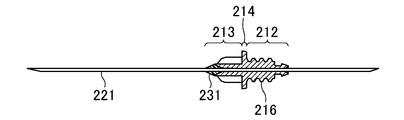
- FIG. 2 is a cross-sectional view showing an example of a connector connected to the blood collection holder.
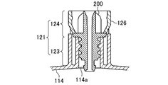
- FIG. 3 is an enlarged cross-sectional view of the connecting portion.
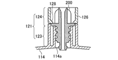
- FIG. 4 is a cross-sectional view showing a modification of the connecting portion.
- 5 (a) and 5 (b) show a modification of the connecting portion
- FIG. 5 (a) is a cross-sectional view
- FIG. 5 (b) is a top view.
- FIG. 6 is a top view showing a modified example of the connecting portion.
- FIG. 7 is a top view showing a modified example of the connecting portion.
- FIG. 8 is a cross-sectional view showing a modified example of the connecting portion.
- FIG. 1A and FIG. 1B show a blood collection holder 100 according to an embodiment.
- the blood collection holder 100 has a cylindrical holder main body 110 having a top plate portion 114 provided on the distal end side, and a cylindrical connection portion 121 protruding from the top plate portion 114.
- the side that is the patient side during use is the distal side. Further, the vertical direction will be described in a state where the holder main body is on the lower side as shown in FIG.
- a connector 200 as shown in FIG. 2 can be attached to the blood collection holder 100, for example.
- FIG. 2 shows an example in which blood sampling needles 221 at both heads are bonded to the connector 200 with an adhesive 231.
- the connector 200 has a base portion 212 with a male screw 216 cut, a hub 213 to which a blood collection needle 221 and the like are fixed, and a flange portion 214 provided between the base portion 212 and the hub 213.
- the device attached to the connector 200 is not limited to the double-ended blood collection needle 221.
- a tube with a winged needle can be attached.
- the outer needle of an indwelling needle can also be attached.
- the connecting portion 121 includes a first portion 123 and a second portion 124 provided on the distal end side with respect to the first portion 123.
- the first portion 123 has an internal thread that engages with an external thread provided on the base 212 of the connector 200.
- the second portion 124 has a lock portion that locks the connector 200.
- the lock portion may be a flexible convex portion provided on the side wall of the second portion 124 and protruding inward.
- the flexible convex portion is an elastically deformable tongue-shaped portion 126 provided on the side wall. A part of the side wall of the tongue-like portion 126 is cut out, the holder main body 110 side is a free end, and the opposite side of the holder main body 110 is a fixed end.
- the second portion 124 has a slightly larger inner diameter than the outer diameter of the flange portion 214 of the connector 200 in a portion where the tongue-like portion 126 is not provided.
- the tongue-like portion 126 is bent so that the free end side is inside the fixed end side. For this reason, the minimum value of the inner diameter at the portion where the tongue-like portion 126 is provided is smaller than the outer diameter of the collar portion 214. Further, the distance between the lower end portion of the tongue-like portion 126 and the upper end portion of the first portion 123 is slightly larger than the thickness of the flange portion 214. Thereby, the tongue-like portion 126 functions as a lock portion that locks the connector 200.
- the collar part 214 comes into contact with the tongue-like part 126 which is a lock part. Since the tongue-like portion 126 can be elastically deformed and spread outward, when the connector 200 is further screwed, the collar portion 214 moves to the holder body 110 side while spreading the tongue-like portion 126. When the collar 214 exceeds the position of the tongue piece 126, the tongue piece 126 is restored and rides on the collar 214 as shown in FIG. 3, and the connector 200 is locked.
- the connector 200 Since the connector 200 is locked by the tongue-shaped portion 126, there is almost no possibility that the connector 200 is detached from the connection portion 121 due to vibration or the like. Further, there is almost no possibility that the connector 200 is detached when the blood collection tube is inserted. However, when the connector 200 is rotated in reverse by applying a great force, the tongue piece 126 can be overcome. Therefore, the connector 200 can be separated from the blood collection holder 100 after use.
- the opposite side of the holder body 110 from the top plate portion 114 is an open end 113 into which a blood collection tube can be inserted.
- the top plate portion 114 of the holder main body 110 has a through hole 114a at the center.
- the through hole 114 a communicates with the connection part 121.
- a flange 115 can be provided at the open end 113.
- the blood collection tube can be easily inserted.
- the flange 115 may be provided as necessary, and may not be provided.
- the flange 115 may be formed by a member different from the holder main body 110.
- the diameter of the holder main body 110 can be gradually reduced from the opening end 113 toward the top plate portion 114. Thereby, insertion of a blood collection tube becomes easy.
- the diameter of the holder body 110 may be constant.
- the inner side of the holder main body 110 may be smooth, but a blood collection tube holding part can also be provided. By providing the blood collection tube holding part, it becomes easy to hold the blood collection tube in the holder main body 110.
- the blood collection tube holder can be a protrusion that holds the blood collection tube from the side surface or a leaf spring. Further, another member that is elastically deformed can be inserted into the holder main body 110 to form the blood collection tube holding portion.
- the outside of the holder body 110 may be smooth, but may be provided with irregularities.
- the holder main body 110 and the connection part 121 can be integrally formed. However, it is also possible to assemble the holder main body 110 and the connecting portion 121 after forming them separately.
- the holder body 110 and the connection part 121 may be formed of any material, but can be formed of a resin such as polyethylene or polypropylene.
- the blood collection holder 100 of the present embodiment has a configuration in which the tongue-shaped portion 126 which is a lock portion is bent inward at the free end side.
- any configuration may be used as long as the inner diameter of the second portion 124 is slightly smaller than the outer diameter of the flange portion 214 due to the tongue-shaped portion 126 that is elastically deformed.
- a claw portion 128 that protrudes inward may be provided at the free end of the tongue-like portion 126.
- the configuration in which the flexible convex portion serving as the lock portion is the tongue piece portion 126 is shown.
- the lock portion having such a configuration has an advantage that the device is easily fitted and is not easily detached.
- other configurations may be used as long as the inner diameter of the second portion 124 can be reduced to the extent that the collar portion 214 can get over the lock portion.
- a protrusion provided on the inner wall of the second portion 124 can be used as a lock portion.
- FIG. 5 (a) and 5 (b) show a modification in which a plurality of independent protrusions 126A are provided as convex portions serving as lock portions.
- a plurality of protrusions 126 ⁇ / b> A are provided along the inner periphery of the second portion 124.
- the minimum value of the inner diameter at the portion where the protrusion 126 ⁇ / b> A is provided is slightly smaller than the outer diameter of the flange 214. Since the resin connection portion 121 can be elastically deformed to some extent, the flange portion 214 can get over the protrusion portion 126A.
- Such a lock part has an advantage that it is easy to form.
- the number of protrusions 126A is not particularly limited. Further, the protrusions 126A can be provided at unequal intervals. Although an example is shown in which the circumferential width and the axial height of all the protruding portions 126A are equal, protruding portions having different at least one of the circumferential width and the axial height may be mixed. Although an example in which a plurality of protrusions 126A are provided has been shown, the protrusion 126A may be one.
- FIG. 6 shows a modification in which a continuous ridge 126B is provided as a protrusion.
- the protruding portion 126 ⁇ / b> B is continuously provided along the inner periphery of the second portion 124.
- the lock portion having such a configuration has an advantage that the device is less likely to come off than the point-like protrusion.
- the protruding portion 126B having a constant height from the inner wall surface is provided, and the inner shape of the second portion 124 is also circular in the portion where the protruding portion 126B is provided.
- FIG. 7 shows a modified example in which a ridge 126C whose height from the inner wall surface changes is provided.
- the lock portion having such a configuration has an advantage that the device is more easily fitted than a continuous protrusion having a constant height.
- the inner shape of the second portion 124 in the portion where the ridge portion 126 ⁇ / b> C is provided is a regular hexagonal shape.
- the inner shape generated by the protruding line portion 126C may be any shape, and may be, for example, a triangular shape or a quadrangular shape.
- a straight side is generated by the protruding line portion 126C
- a curved side can be generated by the protruding line portion 126C.
- the inner shape of the second portion 124 may be a lens shape, an elliptical shape, or the like due to the convex portion 126C.
- FIG. 7 shows an example in which the protruding portion 126C has a portion that does not protrude from the inner wall surface, it may protrude from the inner wall surface in all portions.
- the convex part may be a combination of a convex part and an independent protruding part.
- it can be set as the structure which a part of protruding item
- the cross-sectional shape along the axial direction of the protruding portion can be, for example, a shape in which the angle formed with the inner wall surface is larger on the holder body 110 side than on the opposite side. In this way, the flange portion 214 can easily get over the protrusion in the direction in which the connector 200 is screwed, and the flange portion 214 can hardly get over the protrusion in the direction in which the connector 200 is loosened.
- the minimum value of the inner diameter of the lock part depends on the material of the connection part and the connector, but can be a value that is 0.5% to 2% smaller than the diameter of the collar part. By setting it to such a value, it is possible to make it difficult for the connector to loosen and to easily screw the connector.
- connection portion 121 protrudes from the top plate portion 114 toward the front end side.
- the connection portion 121 may protrude from the top plate portion 114 toward the opening end 113.
- the example in which the convex portion serving as the lock portion is the independent projection portion 126 ⁇ / b> A is shown.
- the connection portion 121 protruding from the top plate portion 114 to the tip side is provided, Or a tongue-like part.
- the blood collection holder of the present disclosure is useful as a blood collection holder because the connector is unlikely to loosen or fall off and is easily connected.
Landscapes
- Health & Medical Sciences (AREA)
- Life Sciences & Earth Sciences (AREA)
- Heart & Thoracic Surgery (AREA)
- Medical Informatics (AREA)
- Biophysics (AREA)
- Pathology (AREA)
- Engineering & Computer Science (AREA)
- Biomedical Technology (AREA)
- Hematology (AREA)
- Physics & Mathematics (AREA)
- Molecular Biology (AREA)
- Surgery (AREA)
- Animal Behavior & Ethology (AREA)
- General Health & Medical Sciences (AREA)
- Public Health (AREA)
- Veterinary Medicine (AREA)
- Measurement Of The Respiration, Hearing Ability, Form, And Blood Characteristics Of Living Organisms (AREA)
Abstract
採血ホルダ(100)は、先端側に天板部(114)を有する筒状のホルダ本体(110)と、天板部(114)に配置され、コネクタが接続される接続部(121)とを備えている。接続部(121)は、コネクタに設けられた雄ねじと係合する雌ねじを有する第1の部分(123)と、第1の部分(123)よりも先端側に設けられた第2の部分(124)とを有している。第2の部分(124)は、内径が前記コネクタに設けられた鍔部よりも小さく、鍔部が乗り越えることができるロック部(126)を有している。
Description
本開示は、採血ホルダに関する。
被検者から採血する際には、採血ホルダと真空採血管とを用いる方法が一般に用いられている。採血ホルダは、後端部から真空採血管を挿入できるホルダ本体に両頭の採血針が取り付けられている。一般に、採血針はホルダ本体に分離可能に取り付けられた状態で医療現場に供給される。採血針が予めホルダ本体に取り付けられているため、すぐに使用することができる。また、採血針をホルダ本体に取り付ける際に採血針が汚染されたり、誤穿刺等の事故が生じたりするおそれも低減できる。一方、採血針をホルダ本体から分離できるため、採血後には、採血針を分別して廃棄することができる。
採血の際には、採血針がホルダ本体に確実に取り付けられていることが重要である。採血針をホルダ本体に確実に取り付けるために、ねじ部を有するコネクタに採血針を接着し、コネクタをホルダ本体の接続部にねじ込むことが行われている(例えば、特許文献1を参照。)。
しかしながら、従来のねじ込み式の採血ホルダは、ねじ込まれているコネクタが、輸送時の振動等により緩んだり、ホルダ本体から外れたりするという問題がある。コネクタをねじ込むと共に接着剤等で固定する方法も考えられるが、ホルダ本体によく用いられるポリプロピレンは接着剤による接着が困難であるという問題がある。また、使用後に採血針をホルダ本体から分離することが困難となるという問題もある。また、緩み止めのピンを設けたりする方法も考えられるが、ピンを取り付けたりする工程が増えるため、生産性が低下するという問題がある。両頭の採血針に限らず、ホルダ本体にコネクタを介して針又はチューブ等を接続する場合には同様の問題が発生する。
また、従来のねじ込み式の採血ホルダには、採血管を挿入する際に、コネクタが緩んだり、脱落したりしやすいという問題もある。
本開示は、コネクタの緩み又は脱落が生じにくく且つ組み立てが容易な採血ホルダを実現できるようにすることを目的とする。
採血ホルダの一態様は、先端側に天板部を有する筒状のホルダ本体と、天板部に配置されコネクタが接続される接続部とを備え、接続部は、コネクタに設けられた雄ねじと係合する第1の部分と、第1の部分よりも先端側に設けられた第2の部分とを有し、第2の部分は、内径がコネクタに設けられた鍔部よりも小さく、且つ鍔部が乗り越えることができるロック部を有する。
採血ホルダの一態様において、接続部は、天板部から先端側に突出する筒状とすることができる。
採血ホルダに一態様において、ロック部は、第2の部分における内壁に設けられた凸部とすることができる。
この場合において、凸部は、第2の部分の内周に沿って設けられた、1つ以上の突起部とすることができる。
本開示の採血ホルダによれば、輸送中及び採血管の挿入時においてコネクタの緩み又は脱落が生じにくく且つ組み立てが容易な採血ホルダを実現できる。
図1(a)及び図1(b)は一実施形態に係る採血ホルダ100を示している。採血ホルダ100は、先端側に設けられた天板部114を有する筒状のホルダ本体110と、天板部114から突出する筒状の接続部121とを有している。以下において特に断りが無い限り、使用時に患者側となる側を先端側とする。また、図1(a)に示すようにホルダ本体を下側にした状態において上下方向を説明する。
採血ホルダ100には、例えば、図2に示すようなコネクタ200を取り付けることができる。図2には、コネクタ200に両頭の採血針221が接着剤231により接着された例を示している。コネクタ200は、雄ねじ216が切られた基部212と、採血針221等が固定されるハブ213と、基部212とハブ213との間に設けられた鍔部214とを有している。コネクタ200に取り付けるデバイスは、両頭の採血針221に限らない。例えば、翼状針の付いたチューブ等を取り付けることができる。また、留置針の外針を取り付けることもできる。
図3に示すように、接続部121は、第1の部分123と、第1の部分123よりも先端側に設けられた第2の部分124とを有している。第1の部分123は、コネクタ200の基部212に設けられた雄ねじと係合する雌ねじを有する。第2の部分124は、コネクタ200をロックするロック部を有している。ロック部は第2の部分124の側壁に設けられ内側に突出する可撓性の凸部とすることができる。
図1(a)及び図1(b)においては、可撓性の凸部を側壁に設けられた弾性変形可能な舌片状部126としている。舌片状部126は、側壁の一部が切り抜かれ、ホルダ本体110側が自由端となり、ホルダ本体110と反対側が固定端となっている。
第2の部分124は、舌片状部126が設けられていない部分においては、コネクタ200の鍔部214の外径よりもわずかに内径が大きい。舌片状部126は自由端側が固定端側よりも内側になるように曲げられている。このため、舌片状部126が設けられた部分における内径の最小値は、鍔部214の外径よりも小さい。また、舌片状部126の下端部と第1の部分123の上端部との間隔は鍔部214の厚さよりもわずかに大きくなっている。これにより、舌片状部126は、コネクタ200をロックするロック部として機能する。
コネクタ200を接続部121にねじ込んでいくと、鍔部214がロック部である舌片状部126に当接する。舌片状部126は弾性変形して外側に拡がることができるため、コネクタ200をさらにねじ込むと、鍔部214は舌片状部126を拡げながらホルダ本体110側に移動する。鍔部214が舌片状部126の位置を越えると、舌片状部126は復元し、図3に示すように、鍔部214の上に乗り上げ、コネクタ200がロックされる。
舌片状部126によりコネクタ200がロックされるため、振動等によってコネクタ200が接続部121から外れるおそれはほとんど無い。また、採血管の挿入時にもコネクタ200が外れるおそれはほとんど無い。しかし、大きな力を掛けてコネクタ200を逆回転させると、舌片状部126を乗り越えさせることができる。従って、使用後にコネクタ200を採血ホルダ100から分離することができる。
ホルダ本体110の天板部114と反対側は、採血管を挿入することができる開口端113となっている。ホルダ本体110の天板部114は、中央部に貫通孔114aを有している。貫通孔114aは接続部121と連通している。
開口端113にはフランジ115を設けることができる。フランジ115を設けることにより、採血管の挿入操作が容易となる。また、フランジ115を下にしてホルダ本体110を自立させることが容易となる。また、採血ホルダ100を横にしてテーブル等の上に置いた場合に転がりにくくすることができる。フランジ115は、必要に応じて設ければよく、設けなくてもよい。また、ホルダ本体110と別の部材によってフランジ115を形成してもよい。
ホルダ本体110は、開口端113から天板部114に向かって次第に径が小さくなるようにすることができる。これにより、採血管の挿入が容易となる。但し、ホルダ本体110の径は一定であってもよい。ホルダ本体110の内側は平滑であってもよいが、採血管保持部を設けることもできる。採血管保持部を設けることにより、採血管をホルダ本体110内に保持することが容易となる。採血管保持部は、採血管を側面から押さえる突起としたり、板ばねとしたりすることができる。また、弾性変形する別部材をホルダ本体110内に挿入して採血管保持部とすることもできる。ホルダ本体110の外側は平滑であってもよいが、凹凸が設けられていてもよい。
ホルダ本体110と接続部121とは、一体に形成することができる。但し、ホルダ本体110と接続部121とを別々に形成した後、組み立てることもできる。ホルダ本体110及び接続部121は、どのような材料により形成されていてもよいが、例えばポリエチレン又はポリプロピレン等の樹脂により形成することができる。
本実施形態の採血ホルダ100は、ロック部である舌片状部126を自由端側が内側に曲げられた構成とした。しかし、弾性変形する舌片状部126により第2の部分124の内径が鍔部214の外径よりもわずかに小さくなればどのような構成としてもよい。例えば、図4に示すように、舌片状部126の自由端に内側に突出する爪部128を設けた構成とすることができる。
本実施形態においては、ロック部となる可撓性の凸部を舌片状部126とした構成を示した。このような構成のロック部は、デバイスがはめ込みやすく且つ外れにくいという利点を有する。しかし、ロック部において第2の部分124の内径を鍔部214が乗り越えられる程度に小さくすることができれば、他の構成としてもよい。例えば、第2の部分124の内壁に設けた突起部をロック部とすることができる。
図5(a)及び図5(b)は、ロック部となる凸部として、複数の独立した突起部126Aを設けた変形例を示している。突起部126Aは第2の部分124の内周に沿って複数設けられている。突起部126Aが設けられた部分における内径の最小値は鍔部214の外径よりもわずかに小さい。樹脂製の接続部121はある程度の弾性変形が可能であるため、鍔部214は突起部126Aを乗り越えることができる。このような、構成のロック部は形成が容易であるという利点を有する。突起部126Aが等間隔に10個設けられた例を示しているが、突起部126Aの数は特に限定されない。また、突起部126Aを不等間隔に設けることもできる。全ての突起部126Aの周方向の幅及び軸方向の高さが等しい例を示したが、周方向の幅及び軸方向の高さの少なくとも一方が異なる突起部が混在していてもよい。突起部126Aが複数設けられている例を示したが、突起部126Aを1つとすることもできる。
図6は、突起部として、連続した凸条部126Bを設けた変形例を示している。凸条部126Bは第2の部分124の内周に沿って連続して設けられている。このような構成のロック部は、点状の突起部よりもデバイスが外れにくいという利点を有する。図6においては、内壁面からの高さが一定である凸条部126Bが設けられ、凸条部126Bが設けられた部分においても第2の部分124の内形状が円形状となっている。しかし、内壁面からの高さが一定でない凸条部を設けることもできる。
図7は、内壁面からの高さが変化する凸条部126Cを設けた変形例を示している。このような構成のロック部は、高さが一定の連続した凸条部よりもデバイスがはめ込みやすいという利点を有する。図7においては、凸条部126Cが設けられた部分における第2の部分124の内形状が正六角形状となっている。但し、凸条部126Cによって生じる内形状はどのような形状であってもよく、例えば三角形状又は四角形状等とすることができる。また、凸条部126Cによって直線状の辺が生じる例を示したが、凸条部126Cによって曲線状の辺が生じるようにすることができる。例えば、凸条部126Cによって第2の部分124の内形状がレンズ状又は楕円状等となっていてもよい。図7においては、凸条部126Cが内壁面から突出していない部分を有している例を示しているが、全ての部分において内壁面から突出していてもよい。
凸部は、凸条部と独立した突起部とを組み合わせてもよい。例えば、凸条部の一部がさらに突出した構成とすることができる。突起部と舌片状部とを組み合わせることも可能である。
突起部の軸方向に沿った断面形状は、例えば内壁面となす角が、ホルダ本体110側において反対側よりも大きくなっている形状とすることができる。このようにすれば、コネクタ200をねじ込む方向には鍔部214が突起部を乗り越え易くし、コネクタ200が緩む方向には鍔部214が突起部を乗り越えにくくすることができる。
ロック部における内径の最小値は、接続部及びコネクタの材質等にもよるが、鍔部の径よりも0.5%~2%程度小さい値とすることができる。このような値とすることにより、コネクタの緩みを発生しにくくすることができると共に、コネクタのねじ込みも容易に行うことができる。
図1~図7において、接続部121が天板部114から先端側に突出している例を示した。しかし、図8に示すように、接続部121が天板部114から開口端113側に突出している構成としてもよい。図8においては、ロック部となる凸部が独立した突起部126Aである例を示したが、天板部114から先端側に突出した接続部121を設ける場合と同様に、連続した凸条部としたり、舌片状部としたりすることができる。
本開示の採血ホルダは、コネクタの緩み又は脱落が生じにくく且つ接続が容易であり、採血ホルダとして有用である。
100 採血ホルダ
110 ホルダ本体
113 開口端
114 天板部
114a 貫通孔
115 フランジ
121 接続部
123 第1の部分
124 第2の部分
126 舌片状部
126A 突起部
126B 凸条部
126C 凸条部
128 爪部
200 コネクタ
212 基部
213 ハブ
214 鍔部
221 採血針
231 接着剤
110 ホルダ本体
113 開口端
114 天板部
114a 貫通孔
115 フランジ
121 接続部
123 第1の部分
124 第2の部分
126 舌片状部
126A 突起部
126B 凸条部
126C 凸条部
128 爪部
200 コネクタ
212 基部
213 ハブ
214 鍔部
221 採血針
231 接着剤
Claims (4)
- 先端側に天板部を有する筒状のホルダ本体と、
前記ホルダ本体の天板部に配置され、コネクタが接続される接続部とを備え、
前記接続部は、前記前記コネクタに設けられた雄ねじと係合する第1の部分と、前記第1の部分よりも先端側に設けられた第2の部分とを有し、
前記第2の部分は、内径が前記コネクタに設けられた鍔部よりも小さく、且つ前記鍔部が乗り越えることができるロック部を有する、採血ホルダ。 - 前記接続部は、前記天板部から先端側に突出する筒状である請求項1に記載の採血ホルダ。
- 前記ロック部は、前記第2の部分における内壁に設けられた凸部である、請求項1又は2に記載の採血ホルダ。
- 前記凸部は、前記第2の部分の内周に沿って設けられた、一つ以上の突起部である、請求項3に記載の採血ホルダ。
Priority Applications (1)
| Application Number | Priority Date | Filing Date | Title |
|---|---|---|---|
| JP2016529047A JP6614142B2 (ja) | 2014-06-18 | 2015-06-16 | 採血ホルダ |
Applications Claiming Priority (2)
| Application Number | Priority Date | Filing Date | Title |
|---|---|---|---|
| JP2014-125165 | 2014-06-18 | ||
| JP2014125165 | 2014-06-18 |
Publications (1)
| Publication Number | Publication Date |
|---|---|
| WO2015194161A1 true WO2015194161A1 (ja) | 2015-12-23 |
Family
ID=54935166
Family Applications (1)
| Application Number | Title | Priority Date | Filing Date |
|---|---|---|---|
| PCT/JP2015/002997 Ceased WO2015194161A1 (ja) | 2014-06-18 | 2015-06-16 | 採血ホルダ |
Country Status (2)
| Country | Link |
|---|---|
| JP (2) | JP6614142B2 (ja) |
| WO (1) | WO2015194161A1 (ja) |
Cited By (1)
| Publication number | Priority date | Publication date | Assignee | Title |
|---|---|---|---|---|
| JP7678961B1 (ja) | 2019-06-13 | 2025-05-19 | 株式会社トップ | 採血管ホルダー及び採血キット |
Families Citing this family (1)
| Publication number | Priority date | Publication date | Assignee | Title |
|---|---|---|---|---|
| JP7851520B2 (ja) * | 2021-05-18 | 2026-04-27 | 株式会社トップ | 採血管ホルダ |
Citations (2)
| Publication number | Priority date | Publication date | Assignee | Title |
|---|---|---|---|---|
| JP2007152083A (ja) * | 2005-11-08 | 2007-06-21 | Nipro Corp | 採血針セット |
| JP2008307193A (ja) * | 2007-06-13 | 2008-12-25 | Sekisui Chem Co Ltd | 採血ホルダー |
Family Cites Families (4)
| Publication number | Priority date | Publication date | Assignee | Title |
|---|---|---|---|---|
| JPH02297342A (ja) * | 1988-09-28 | 1990-12-07 | Terumo Corp | 両刀針形の医療用針とホルダーを用いる採血及び/又は注射装置、並びに該装置に用いる両刀針形の医療用針及びホルダー |
| JP2000166901A (ja) * | 1998-12-01 | 2000-06-20 | Sekisui Chem Co Ltd | 採血管ホルダー |
| JP2005342100A (ja) * | 2004-06-01 | 2005-12-15 | Techno Medica Co Ltd | 真空採血管用採血針付き採血ホルダー |
| US20100286558A1 (en) * | 2009-04-08 | 2010-11-11 | Stat Medical Devices, Inc. | Fluid collection/injection device having quick release/removable double-ended needle and safety system |
-
2015
- 2015-06-16 JP JP2016529047A patent/JP6614142B2/ja active Active
- 2015-06-16 WO PCT/JP2015/002997 patent/WO2015194161A1/ja not_active Ceased
-
2019
- 2019-11-07 JP JP2019202443A patent/JP2020028727A/ja active Pending
Patent Citations (2)
| Publication number | Priority date | Publication date | Assignee | Title |
|---|---|---|---|---|
| JP2007152083A (ja) * | 2005-11-08 | 2007-06-21 | Nipro Corp | 採血針セット |
| JP2008307193A (ja) * | 2007-06-13 | 2008-12-25 | Sekisui Chem Co Ltd | 採血ホルダー |
Cited By (4)
| Publication number | Priority date | Publication date | Assignee | Title |
|---|---|---|---|---|
| JP7678961B1 (ja) | 2019-06-13 | 2025-05-19 | 株式会社トップ | 採血管ホルダー及び採血キット |
| JP7678962B1 (ja) | 2019-06-13 | 2025-05-19 | 株式会社トップ | 採血管ホルダー及び採血キット |
| JP2025081782A (ja) * | 2019-06-13 | 2025-05-27 | 株式会社トップ | 採血管ホルダー及び採血キット |
| JP2025081781A (ja) * | 2019-06-13 | 2025-05-27 | 株式会社トップ | 採血管ホルダー及び採血キット |
Also Published As
| Publication number | Publication date |
|---|---|
| JPWO2015194161A1 (ja) | 2017-04-20 |
| JP2020028727A (ja) | 2020-02-27 |
| JP6614142B2 (ja) | 2019-12-04 |
Similar Documents
| Publication | Publication Date | Title |
|---|---|---|
| CA2610534C (en) | Luer-lock type cylindrical tip of syringe | |
| JP4906859B2 (ja) | カテーテル固定器具 | |
| US12234945B2 (en) | Assembly including a mounting portion and an implement-retaining portion | |
| EP1621782B1 (en) | Female attachment and obturator including it | |
| JP2013505755A (ja) | 医療用チューブの連結デバイス | |
| KR20150087346A (ko) | 주사 바늘 조립체 | |
| JP6614142B2 (ja) | 採血ホルダ | |
| US20200078578A1 (en) | Female connector | |
| CN104047937B (zh) | 多功能适配器 | |
| JP2019005053A (ja) | メスコネクタ | |
| JP2017000831A (ja) | 接続部材 | |
| US7179243B2 (en) | Syringe with a snapping device for backward pulling the needle into the syringe after syringing | |
| JP5977295B2 (ja) | ホース継手 | |
| US6409704B1 (en) | Retractable safety syringe | |
| JP4361962B1 (ja) | 容器兼用注射器 | |
| EP2570165A3 (en) | Filter unit | |
| US20130304038A1 (en) | Female-side connector | |
| JP6013147B2 (ja) | 変換アダプタ | |
| JP2005342100A (ja) | 真空採血管用採血針付き採血ホルダー | |
| US20160030682A1 (en) | Needle assembly retainer | |
| JP2008206657A (ja) | 注射器用指掛け補助具 | |
| US20170055739A1 (en) | Holding Device for Preventing Straw from Dropping | |
| JP2015000155A (ja) | 医療分野で用いられるコネクタ用抜止具およびコネクタ用抜止具セット | |
| JP3114468U (ja) | 医療用針 | |
| JP2013011336A (ja) | チューブ継手 |
Legal Events
| Date | Code | Title | Description |
|---|---|---|---|
| 121 | Ep: the epo has been informed by wipo that ep was designated in this application |
Ref document number: 15810251 Country of ref document: EP Kind code of ref document: A1 |
|
| ENP | Entry into the national phase |
Ref document number: 2016529047 Country of ref document: JP Kind code of ref document: A |
|
| NENP | Non-entry into the national phase |
Ref country code: DE |
|
| 122 | Ep: pct application non-entry in european phase |
Ref document number: 15810251 Country of ref document: EP Kind code of ref document: A1 |