WO2015194014A1 - Système de communication sans fil, procédé de communication sans fil, dispositif sans fil et station de base sans fil - Google Patents
Système de communication sans fil, procédé de communication sans fil, dispositif sans fil et station de base sans fil Download PDFInfo
- Publication number
- WO2015194014A1 WO2015194014A1 PCT/JP2014/066341 JP2014066341W WO2015194014A1 WO 2015194014 A1 WO2015194014 A1 WO 2015194014A1 JP 2014066341 W JP2014066341 W JP 2014066341W WO 2015194014 A1 WO2015194014 A1 WO 2015194014A1
- Authority
- WO
- WIPO (PCT)
- Prior art keywords
- wireless
- communication
- base station
- wireless device
- cue
- Prior art date
Links
Images


Classifications
-
- H—ELECTRICITY
- H04—ELECTRIC COMMUNICATION TECHNIQUE
- H04W—WIRELESS COMMUNICATION NETWORKS
- H04W76/00—Connection management
- H04W76/10—Connection setup
- H04W76/14—Direct-mode setup
-
- H—ELECTRICITY
- H04—ELECTRIC COMMUNICATION TECHNIQUE
- H04W—WIRELESS COMMUNICATION NETWORKS
- H04W72/00—Local resource management
- H04W72/50—Allocation or scheduling criteria for wireless resources
- H04W72/51—Allocation or scheduling criteria for wireless resources based on terminal or device properties
-
- H—ELECTRICITY
- H04—ELECTRIC COMMUNICATION TECHNIQUE
- H04W—WIRELESS COMMUNICATION NETWORKS
- H04W48/00—Access restriction; Network selection; Access point selection
- H04W48/08—Access restriction or access information delivery, e.g. discovery data delivery
-
- H—ELECTRICITY
- H04—ELECTRIC COMMUNICATION TECHNIQUE
- H04W—WIRELESS COMMUNICATION NETWORKS
- H04W72/00—Local resource management
- H04W72/50—Allocation or scheduling criteria for wireless resources
- H04W72/53—Allocation or scheduling criteria for wireless resources based on regulatory allocation policies
-
- H—ELECTRICITY
- H04—ELECTRIC COMMUNICATION TECHNIQUE
- H04W—WIRELESS COMMUNICATION NETWORKS
- H04W72/00—Local resource management
- H04W72/50—Allocation or scheduling criteria for wireless resources
- H04W72/54—Allocation or scheduling criteria for wireless resources based on quality criteria
-
- H—ELECTRICITY
- H04—ELECTRIC COMMUNICATION TECHNIQUE
- H04W—WIRELESS COMMUNICATION NETWORKS
- H04W72/00—Local resource management
- H04W72/50—Allocation or scheduling criteria for wireless resources
- H04W72/54—Allocation or scheduling criteria for wireless resources based on quality criteria
- H04W72/541—Allocation or scheduling criteria for wireless resources based on quality criteria using the level of interference
-
- H—ELECTRICITY
- H04—ELECTRIC COMMUNICATION TECHNIQUE
- H04W—WIRELESS COMMUNICATION NETWORKS
- H04W8/00—Network data management
- H04W8/005—Discovery of network devices, e.g. terminals
-
- H—ELECTRICITY
- H04—ELECTRIC COMMUNICATION TECHNIQUE
- H04W—WIRELESS COMMUNICATION NETWORKS
- H04W84/00—Network topologies
- H04W84/18—Self-organising networks, e.g. ad-hoc networks or sensor networks
-
- H—ELECTRICITY
- H04—ELECTRIC COMMUNICATION TECHNIQUE
- H04W—WIRELESS COMMUNICATION NETWORKS
- H04W48/00—Access restriction; Network selection; Access point selection
- H04W48/08—Access restriction or access information delivery, e.g. discovery data delivery
- H04W48/12—Access restriction or access information delivery, e.g. discovery data delivery using downlink control channel
-
- H—ELECTRICITY
- H04—ELECTRIC COMMUNICATION TECHNIQUE
- H04W—WIRELESS COMMUNICATION NETWORKS
- H04W88/00—Devices specially adapted for wireless communication networks, e.g. terminals, base stations or access point devices
- H04W88/02—Terminal devices
- H04W88/06—Terminal devices adapted for operation in multiple networks or having at least two operational modes, e.g. multi-mode terminals
-
- H—ELECTRICITY
- H04—ELECTRIC COMMUNICATION TECHNIQUE
- H04W—WIRELESS COMMUNICATION NETWORKS
- H04W92/00—Interfaces specially adapted for wireless communication networks
- H04W92/16—Interfaces between hierarchically similar devices
- H04W92/18—Interfaces between hierarchically similar devices between terminal devices
Definitions
- the present invention relates to a wireless communication system, a wireless communication method, a wireless device, and a wireless base station.
- D2D communication is an example of a technology in which wireless devices such as mobile stations directly perform wireless communication without using a wireless base station.
- D2D communication is an example of alternative or auxiliary public safety communication in a scenario in which wireless communication via a wireless base station (may be referred to as “cellular communication”) becomes impossible due to a large-scale disaster, for example. Is discussed.
- wireless communication performance performance, characteristics, efficiency, and the like as a wireless communication system (may be collectively referred to as “wireless communication performance”) may be reduced.
- one of the objects of the present invention is to improve wireless communication performance.
- a wireless communication system (or wireless communication method) is used for communication between wireless devices in which a first wireless device that wirelessly communicates with a wireless base station does not pass between the second wireless devices via the wireless base station.
- the identification information of the first wireless device is transmitted using the wireless resource allocated to the first wireless device.
- the wireless device includes a transmission unit that transmits identification information of the wireless device using a wireless resource allocated for communication between wireless devices that does not pass through a wireless base station between other wireless devices. .
- the wireless device is a second wireless device that performs communication between the wireless device and the first wireless device without going through the wireless base station, and is a third wireless device that wirelessly communicates with the wireless base station.
- the wireless device includes a receiving unit that receives the identification information of the third wireless device transmitted using the wireless resource allocated for the communication between the wireless devices.
- the radio base station is identified by a receiving unit that receives the identification information of the third wireless device transmitted by the second wireless device, and the identification information received by the receiving unit.
- a control unit that controls a radio resource used by the third radio device for radio communication with the radio base station to a radio resource that does not overlap with the radio resource for communication between the radio devices.
- wireless communication performance can be improved.
- FIG. 3 is a diagram illustrating an example of a procedure for generating a PDCCH transmission signal in the radio base station illustrated in FIG. 1. It is a figure explaining the transmission timing of PUSCH of the mobile station illustrated in FIG. It is a figure which shows typically a mode that the mobile station which performs cellular communication transmits the discovery signal (DS) in the radio
- FIG. 3 shows typically a mode that the radio
- FIG. 6 is a block diagram illustrating a configuration example of a radio base station illustrated in FIGS. 1 and 5.
- FIG. 6 is a block diagram illustrating a configuration example of a mobile station performing D2D communication illustrated in FIGS. 1 and 5.
- FIG. 6 is a block diagram illustrating a configuration example of a mobile station performing cellular communication illustrated in FIGS. 1 and 5.
- FIG. 6 is a sequence diagram for explaining an operation (first interference avoidance method) of the wireless communication system illustrated in FIGS. 1 and 5. It is a sequence diagram explaining operation
- wireless communications system which concerns on 2nd Embodiment. 12 is a flowchart for explaining an operation (third interference avoidance method) of the wireless communication system according to the third embodiment. 12 is a flowchart for explaining an operation (fourth interference avoidance method) of the wireless communication system according to the fourth embodiment.
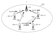
- FIG. 1 is a diagram illustrating a configuration example of a wireless communication system according to the first embodiment.
- the wireless communication system 1 shown in FIG. 1 exemplarily includes one or a plurality of radio base stations 10 and a plurality of mobile stations 20-1 to 20-N (# 1 to #N) (N is an integer of 2 or more). And comprising.
- the mobile stations 20-1 to 20-N may be simply expressed as “mobile station 20”.
- the radio base station 10 forms a radio area 100.
- a mobile station 20 located in the wireless area 100 can wirelessly communicate with the wireless base station 10.
- the radio base station 100 may form a plurality of radio areas 100.
- the radio area 100 is determined according to the reach of radio waves transmitted by the radio base station 10. It may be considered that the maximum reachable range of the radio wave is determined by the maximum transmission power of the radio base station 10.
- Wireless area may be referred to as “cell”, “coverage area” or “communication area”.
- the “cell” may be divided into “sector cells”.
- the “cell” may include a macro cell and a small cell.
- a small cell is an example of a cell having a radio wave coverage (coverage) smaller than that of a macro cell. Small cells may have different names depending on the coverage area. For example, the small cell may be referred to as “femtocell”, “picocell”, “microcell”, “nanocell”, “metrocell”, “homecell”, and the like.
- the radio base station 10 may be referred to as “base station (BS)”, “node B (NB)”, or “evolved NB (eNB)”.
- BS base station
- NB node B
- eNB evolved NB
- the mobile station 20 is an example of a wireless device that can wirelessly communicate with the wireless base station 10 when located in the cell 100.
- the mobile station 20 may be referred to as a radio device, a mobile terminal, a terminal device, or user equipment (UE).
- An example of the mobile station 20 is a mobile phone or a smartphone.
- the mobile station 20 may be a wireless device fixed to a moving body such as a vehicle, an aircraft, or a ship.
- the wireless device may include a sensor device or a meter (measuring instrument) having a wireless communication function that forms a sensor network.
- Wireless communication between the mobile station 20 and the wireless base station 10 may be referred to as “cellular communication”.
- a wireless communication system compliant with 3GPP LTE or LTE-Advanced may be applied to the wireless communication system of cellular communication.
- a wireless communication method based on a method such as “Worldwide Interoperability for Microwave Access, (WiMAX)” (registered trademark) may be applied.
- the radio base station 10 may be communicably connected to a core network not shown in FIG.
- the core network may include a service gateway (SGW), a packet data network gateway (PGW), a mobility management entity (MME), and the like.
- SGW service gateway
- PGW packet data network gateway
- MME mobility management entity
- a communication network including a core network may be referred to as an access network.
- the access network may be referred to as “Evolved Universal Terrestrial Radio Access Network, E-UTRAN”.
- the radio base station 10 may be connected to the core network by, for example, a wired interface.
- the wired interface may be referred to as an “S1 interface”.
- the radio base station 10 may be communicably connected to the core network through a radio interface.
- the radio base station 10 may be communicably connected to another radio base station 10 (not shown in FIG. 1) via a wired interface, for example.
- the wired interface may be referred to as an “X2 interface”.
- the radio base station 10 may be connected to other radio base stations via a radio interface.
- the radio base station 10 allocates radio resources to cellular communication with the mobile station 20 located in the cell 100 formed by the own station 10.
- the allocation of radio resources may be referred to as “scheduling”.
- the mobile station 20 performs cellular communication with the radio base station 10 using radio resources allocated from the radio base station 10.
- Radio resources may be identified by time and frequency, for example. For example, identification of radio resources may be performed in units of divided resources obtained by dividing radio resources that can be used by the radio communication system 1 according to time and frequency.
- the division resource may be referred to as a “resource block (RB)” or a “resource element (RE)”.
- RE may be a minimum unit of radio resource allocation, and may be defined as one symbol of one subcarrier, for example.
- a RE group (REG) may be configured by a plurality of REs.
- one RB may be configured by a plurality of REs.
- one RB may be composed of 12 subcarriers in the frequency domain ⁇ 7 symbols or 6 symbols in the time domain.
- Radio resource allocation (scheduling) may be performed in units of RBs.
- the mobile station 20 can communicate directly with other mobile stations 20 without going through the radio base station 10.
- the communication may be referred to as “Device-to-Device,“ D2D ”communication,“ wireless device communication ”, or“ wireless device direct communication ”.
- FIG. 1 schematically illustrates a state in which a pair of UE 20-1 and UE 20-2 performs D2D communication.
- D2D communication is also useful in scenarios where a cellular communication infrastructure is operating. For example, since the UE 20 can directly communicate with the neighboring UE 20 without going through the remote radio base station 10, the power consumption of the UE 20 can be reduced. Further, by offloading cellular communication traffic to D2D communication, it is possible to reduce the load on the core network side.
- the radio base station 10 may also allocate radio resources used for D2D communication.
- the UE 20 performs D2D communication with other UEs 20 using the radio resource allocated from the radio base station 10.
- the UE 20 that performs D2D communication may be referred to as “DUE” for convenience.
- the UE 20 that performs cellular communication with the radio base station 10 may be referred to as “CUE” for convenience.
- the UE 20 may support both cellular communication and D2D communication.
- radio resources for example, frequency resources
- frequency resources for example, frequency resources
- interference between D2D communication and cellular communication does not occur.
- the system capacity of the wireless communication system 1 may be reduced.
- the usable frequency resource can be increased as compared with the case of FIG.
- radio wave interference may occur.
- a signal of D2D communication may be transmitted using a frequency band allocated to uplink (UL) communication in FDD (Frequency Division Duplex) cellular communication. Therefore, D2D communication and UL cellular communication may interfere with each other.
- UL uplink
- FDD Frequency Division Duplex
- the UL transmission (transmission radio wave) from the CUE 20-3 to the radio base station 10 may interfere with the transmission radio wave from the DUE 20-1 to the DUE 20-2.
- the transmission radio wave of the DUE 20-1 to the DUE 20-2 interferes with UL transmission (transmission radio wave) to the radio base station 10 of the CUE 20-3.
- CUE 20-4 performing cellular communication is located near the cell edge, if transmission power increase control is performed in cellular communication, cellular communication is a large interference source for D2D communication. Become.
- the system capacity as the radio communication system 1 may decrease, and the radio communication performance may be deteriorated.
- the DUE 20 that performs D2D communication attempts to detect a radio resource that is allocated from the radio base station 10 to the CUE 20 that performs cellular communication. If the DUE 20 succeeds in detection, the DUE 20 does not perform D2D communication using the radio resource allocated to the CUE 20 (may be referred to as “suppress”). The DUE 20 may perform D2D communication using a radio resource different from the radio resource assigned to the CUE 20.
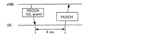
- the detection of the radio resources allocated from the radio base station 10 to the CUE 20 is exemplified by detecting (decoding) uplink (UL) transmission permission information transmitted from the radio base station 10 to the CUE 20 in the cellular communication. Can be implemented.
- the UL transmission permission information may be referred to as UL grant.
- the UL grant is exemplarily transmitted from the radio base station 10 to the CUE 20 through a downlink control channel (Physical-Downlink-Control-Channel, PDCCH).
- PDCCH Physical-Downlink-Control-Channel
- control information indicating “UL grant” for example, as downlink control information (DCI), information on frequency resources used by CUE 20 for transmission using an uplink shared channel (Physical Uplink Shared Channel, PUSCH). May be included.
- DCI downlink control information
- PUSCH Physical Uplink Shared Channel
- UL grant may include UL radio resource allocation information for the CUE 20.
- the format of the control information indicating “UL grant” may be referred to as “DCI format 0” or “DCI format 4”.
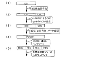
- FIG. 3 shows an example of a procedure for generating a PDCCH transmission signal in the radio base station 10.
- the radio base station 10 performs error detection coding on the DCI and adds a cyclic redundancy check (Cyclic Redundancy Check, CRC) code (bit) to the DCI.
- CRC Cyclic Redundancy Check
- the CRC bits added to the DCI are mask-processed by the bit representation of the identifier of the CUE 20 that is the destination of the PDCCH, as illustrated in (2) to (3) of FIG.
- the identifier of the CUE 20 may be, for example, C-RNTI (Cell-Radio Network Temporary Identifier).
- the C-RNTI is not a permanent identifier, but is an example of a temporary identifier that is assigned every time the CUE 20 requests a connection to the radio base station 10, for example.
- the C-RNTI may be assigned to the CUE 20 by the radio base station 10 in a random access procedure when the CUE 20 randomly accesses the radio base station 10.
- DCI to which CRC bits masked by C-RNTI are added is subjected to error correction coding and data modulation as illustrated in FIGS. 3 (3) to (4), thereby transmitting PDCCH.
- a signal is generated.
- the generated PDCCH transmission signal is concatenated with PDCCH transmission signals addressed to other CUEs 20 and interleaved, as illustrated in (4) to (5) of FIG. 3, and is identified by time and frequency. It is mapped to a radio resource (REG) and transmitted.
- REG radio resource
- the CUE 20 decodes the received signal within a predetermined search range (which may be referred to as a “search space”) if the radio base station 10 is not informed of radio resources that should receive the PDCCH signal from the radio base station 10. Try.
- a predetermined search range which may be referred to as a “search space”
- the CUE 20 performs error detection by canceling the mask of the CRC bits with its own C-RNTI on the decoding result.
- An error-free decoding result indicates “UL grant”.
- the decoding process of the “UL grant” transmitted by the PDCCH in the CUE 20 includes a process of canceling the masking of the CRC bits by the C-RNTI of the CUE 20. Therefore, if the DUE 20 can obtain the C-RNTI of another CUE 20 that performs cellular communication, the DUE 20 tries to decode the PDCCH signal addressed to the CUE 20 using the C-RNTI, and thereby the “UL grant” addressed to the CUE 20 Can be decrypted.
- the DUE 20 can detect the frequency resource allocated to the CUE 20. Therefore, the DUE 20 can avoid interference between the D2D communication and the cellular communication by not performing the D2D communication using the frequency resource allocated to the CUE 20. Note that the DUE 20 attempting to decode the PDCCH signal (UL grant) transmitted to the other CUE 20 via the PDCCH may be referred to as “sniffing”.
- the CUE 20 that performs cellular communication uses frequency resources for D2D communication (may be referred to as “carriers”) allocated from the radio base station 10.
- carriers may be referred to as “carriers”.
- the C-RNTI of the CUE 20 is transmitted.
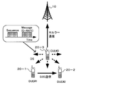
- C-RNTI may be included in a search signal for searching for DUE 20 that performs D2D communication, as schematically illustrated in FIG.
- the search signal may be referred to as a “discovery signal (DS)”.
- the DS is an example of a signal that is transmitted to search for a nearby DUE 20 (discovery).
- the DS is generated based on an identifier (cell-specific ID) common to the CUE 20, and is a radio resource common to the CUE 20. May be sent.
- DS may be a signal in which “Sequence” and “message” are transmitted in a time-sharing manner as illustrated in FIG.
- the “sequence” is an example of a signal used for establishing a radio link for D2D communication, and may be, for example, a signal for detecting a correlation with a signal known between the DUEs 20.
- a physical random access channel (PRACH) or a SRS (Sounding Reference Signal) format may be used.
- the “message” is an example of a signal for transmitting control information, and may be considered as an example of information accompanying the “sequence”.
- the PUSCH format may be used.
- the control information transmitted using the “message” may illustratively have an information amount of about 100 bits.
- the “sequence” and “message” may be transmitted on different physical channels.
- the DS transmission frequency may be set to a frequency (or cycle) that can cope with a change in the position of the CUE 20.
- the CUEs 20 that transmit the DS may be all the CUEs 20 located in the cell 100 or may be limited to some CUEs 20.
- the DS may be transmitted only to the CUE 20 located in a place away from the radio base station 100 (for example, near the cell edge).
- the CUE 20 located in the vicinity of the cell edge can be a large interference source with respect to the surrounding D2D communication by the transmission power increase control of the cellular communication as described above, even when transmitting the DS only to such a CUE 20, Interference avoidance effect can be expected.
- the DUE 20 receives and detects the DS transmitted by the CUE 20. That the DUE 20 can receive and detect the DS means that the CUE 20 that has transmitted the DS can be an interference source for the D2D communication of the DUE 20 that has received the DS. In other words, the DUE 20 can receive and detect only the DS transmitted by the CUE 20 that can be an interference source for its own D2D communication.
- the DUE 20 When the DUE 20 receives the DS, the DUE 20 acquires the C-RNTI included in the “message” of the received DS. Thereafter, the DUE 20 can try to decode the “UL grant” transmitted to the CUE 20 via the PDCCH using the acquired C-RNTI.
- the DUE 20 that has successfully decoded the “UL grant” uses the frequency resource allocation information of the UL indicated in the “UL grant” and the frequency used by the destination CUE 20 of the “UL grant” for transmitting the UL on the PUSCH.
- the resource does not perform D2D communication.
- a PUSCH-based signal may be transmitted and received.
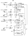
- FIG. 6 is a block diagram illustrating a configuration example of the radio base station 10
- FIG. 7 is a block diagram illustrating a configuration example of the DUE 20
- FIG. 8 is a block diagram illustrating a configuration example of the CUE 20.
- the DUE 20 may be referred to as “DUE 20D” for convenience
- the CUE 20 may be referred to as “CUE 20C” for convenience.
- the radio base station 10 illustratively includes a scheduler 111, a PDSCH generation unit 112A, a PDCCH (UL grant) generation unit 112B, a physical channel multiplexing unit 113, a transmission RF (Radio Frequency) unit 114, and The transmission antenna 115 is provided.
- the scheduler 111 may be regarded as an example of a control unit that comprehensively controls the operation of the radio base station 10 or an example of a functional unit included in the control unit.
- the PDSCH generation unit 112A, the UL grant generation unit 112B, the physical channel multiplexing unit 113, the transmission RF unit 114, and the transmission antenna 115 are regarded as an example of a DL transmission system (transmission unit or transmitter) of the radio base station 10. It's okay.
- the radio base station 10 includes a reception antenna 121, a reception RF unit 122, and a PUSCH demodulation unit 123 as an example of a UL reception system (reception unit or receiver).
- the scheduler 111 exemplarily supports generation of radio resource allocation information for D2D communication and radio resource allocation information for PUSCH.
- Radio resource allocation information may be simply referred to as “resource allocation information”.
- the scheduler 111 includes, for example, a D2D scheduler 111A and a PUSCH scheduler 111B.
- the D2D scheduler 111A illustratively sets wireless resources that may be used for D2D communication.
- the D2D scheduler 111A receives a radio resource allocation request for D2D communication from any UE 20, the D2D scheduler 111A generates radio resource allocation information for D2D communication.
- the PUSCH scheduler 111B when the PUSCH scheduler 111B receives a transmission permission request for PUSCH from any of the UEs 20, the PUSCH scheduler 111B generates radio resource allocation information for PUSCH.
- the PDSCH generation unit 112A generates a signal (PDSCH signal) to be DL transmitted on the PDSCH.
- the PDSCH signal is generated based on, for example, the DL data signal addressed to the CUE 20 received from the above-described core network.
- the data signal may be referred to as “user data” or “user (U) plane signal”.
- the PDCCH generation unit 112B generates a PDCCH signal addressed to the CUE 20.
- the PDCCH signal may include DCI (UL grant) as illustrated in FIG.
- the physical channel multiplexing unit 113 multiplexes the PDSCH signal and the PDCCH signal generated by the PDSCH generation unit 112A and the PDCCH generation unit 112B, and outputs the multiplexed signal to the transmission RF unit 114.
- the transmission RF unit 114 converts (for example, up-converts) the transmission signal of the physical channel multiplexed by the physical channel multiplexing unit 113 into a radio frequency (RF) signal (radio radio wave), and uses the specified transmission power. Output to the transmitting antenna 115.
- RF radio frequency
- the transmission antenna 115 radiates the RF signal from the transmission RF unit 114 into space.
- the receiving antenna 121 receives a radio wave (in other words, a UL RF signal) radiated into the space by any UE 20 and outputs it to the receiving RF unit 122.
- a radio wave in other words, a UL RF signal
- the reception RF unit 122 converts (eg, down-converts) the UL RF signal received by the reception antenna 121 into, for example, a baseband frequency signal (hereinafter sometimes referred to as “BB signal”), and performs PUCCH demodulation. Output to the unit 123.
- BB signal baseband frequency signal
- the PUSCH demodulation unit 123 performs demodulation processing on the BB signal from the reception RF unit 122 to obtain, for example, a PUSCH signal.
- the PUSCH signal may illustratively include user data transmitted to the core network. Further, the PUSCH signal may include a resource allocation request for D2D communication. The demodulated resource allocation request is illustratively given to the D2D scheduler 111A.
- the transmission antenna 115 and the reception antenna 121 may be configured as a transmission / reception antenna shared by DL and UL using an antenna duplexer, for example.
- the transmission RF unit 114 and the reception RF unit 122 may be shared (or integrated) as a transmission / reception RF unit.
- each of the units 111, 112A, 112B, 113, 114, 122, and 123 may be implemented by an arithmetic device having arithmetic capabilities such as a CPU, MPU, or FPGA.
- the arithmetic unit may be referred to as a “hardware processor” or a “processor device”.
- the DUE 20D shown in FIG. 7 supports cellular communication and D2D communication and illustratively corresponds to the DUE 20-1 or 20-2 in FIG. As illustrated in FIG. 7, the DUE 20D includes reception antennas 211 to 213, transmission antennas 214 and 215, reception RF units 221 to 223, and transmission RF units 224 and 225.
- the DUE 20D of FIG. 7 exemplarily includes a D2D data signal demodulation unit 251, a DS detection unit 252, a DS response detection unit 253, a scheduler 261, a DS response generation unit 262, a DS generation unit 263, and a D2D data signal generation unit 264. And a switching unit 265.
- the reception antenna 211 receives a DL RF signal in the cellular communication and outputs it to the reception RF unit 221.
- the reception RF unit 221 down-converts the DL RF signal received by the reception antenna 211 into, for example, a BB signal, and outputs it to the PDSCH demodulation unit 231 and the PDCCH demodulation unit 232.
- the PDSCH demodulator 231 demodulates the PDSCH signal by performing demodulation processing on the BB signal from the reception RF unit 221.
- the resource allocation information is provided to the scheduler 261.
- the allocation information may be referred to as “D2D carrier information”.
- the PDCCH demodulation unit 232 demodulates the PDCCH signal by performing demodulation processing on the BB signal from the reception RF unit 221.
- the demodulation process may include a decoding process such as error correction decoding.
- the demodulated PDCCH signal indicates resource allocation information for PUSCH in cellular communication, the resource allocation information is provided to the scheduler 261.
- the PDCCH demodulation unit 232 based on the C-RNTI included in the “message” of the received DS detected by the DS detection unit 241, as described above, the UL grant included in the PDCCH signal addressed to the other CUE 20 Attempt to demodulate and decode.
- the PDCCH demodulation unit 232 decodes the radio resource allocation information encoded by the radio base station 10 using C-RNTI and transmitted to the CUE 20 using the C-RNTI detected by the DS detection unit 241. It may be considered as an example of a decoding unit.
- the reception antenna 212 receives a UL RF signal in cellular communication and outputs it to the reception RF unit 222.
- the reception RF unit 222 down-converts the UL RF signal received by the reception antenna 221 into, for example, a BB signal and outputs the converted signal to the DS detection unit 241.
- the DS detection unit 241 detects a DS from the BB signal input from the reception RF unit 222. When the DS is detected, the C-RNTI included in the “message” of the DS is given to the PDCCH demodulation unit 232 as information indicating the CUE 20 that is the interference source of the D2D communication.
- the reception RF unit 222 and the DS detection unit 241 are an example of a reception unit that receives the identification information of the CUE 20 transmitted by the CUE 20 that performs radio communication with the radio base station 10 using radio resources allocated for D2D communication. You can catch it.
- the reception antenna 213 receives an RF signal transmitted from another DUE 20D in the D2D communication and outputs the RF signal to the reception RF unit 223.
- the reception RF unit 223 down-converts the reception RF signal of the D2D communication received by the reception antenna 223 into, for example, a BB signal, and converts it to the D2D data signal demodulation unit 251, the DS detection unit 252, and the DS response detection unit 253. Output.
- the D2D data signal demodulation unit 251 demodulates the BB signal input from the reception RF unit 223 to obtain a D2D communication data signal.
- the D2D data signal demodulation unit 251 may be the PUSCH demodulation unit 251 that demodulates the PUSCH signal.
- the DS detection unit 252 detects a DS from the BB signal input from the reception RF unit 223.
- the DS is illustratively equivalent to a DS generated and transmitted by another DUE 20D by the DS generation unit 263 in order to search for a DUE 20D that forms a pair of D2D communication.
- the DS response generation unit 262 In response to the detection of the DS by the DS detection unit 252, the DS response generation unit 262 generates a DS response signal.
- the DS response detection unit 253 detects a DS response signal for the DS generated by the DS generation unit 263 and transmitted to the other DUE 20 from the signal received by the reception RF unit 223. For example, the scheduler 261 is notified that the DS response signal is detected. In response to the detection of the DS response signal, a D2D communication pair with another DUE 20 is formed.
- the scheduler 261 is an example of a control unit that controls cellular communication and D2D communication. For example, the scheduler 261 transmits a resource allocation request for D2D communication to the PUSCH generation unit 242. In response to receiving the resource allocation request, the PUSCH generation unit 242 generates a PUSCH signal addressed to the radio base station 10 including the resource allocation request.
- the scheduler 261 receives the resource allocation information from the PDSCH demodulator 231.
- the scheduler 261 controls the D2D data signal demodulation unit 251 and the D2D data signal generation unit 264 so that D2D communication is performed using the frequency resource indicated by the resource allocation information.
- the scheduler 261 succeeds in demodulating and decoding a PDCCH signal (UL grant) addressed to another CUE 20 serving as an interference source of D2D communication in the PDCCH demodulation unit 232, the resource of the interference source CUE 20 indicated by the UL grant is displayed.
- Receive allocation information The scheduler 261 controls the D2D data signal demodulation unit 251 and the D2D data signal generation unit 264 so as to suppress D2D communication on the frequency resource indicated by the resource allocation information of the interference source CUE20.
- the PUSCH generation unit 242 generates a PUSCH signal including a UL data signal in cellular communication and outputs the PUSCH signal to the transmission RF unit 224.
- the resource allocation request for D2D communication received from the scheduler 261 may be transmitted using the PUSCH signal.
- the transmission RF unit 224 converts (up-converts) the PUSCH signal of the baseband frequency generated by the PUSCH generation unit 242 into an RF signal and outputs the RF signal to the transmission antenna 214.
- the transmission antenna 214 radiates the RF signal from the transmission RF unit 224 to the space.
- the DS generation unit 263 generates a DS for searching for another DUE 20D forming a D2D communication pair.
- the DS is detected by the DS detection unit 252 of another DUE 20D.
- the D2D data signal generation unit 264 generates a transmission data signal for D2D communication including a data signal received from the scheduler 261, for example.
- the D2D data signal generation unit 251 may be a PUSCH generation unit 251 that generates a PUSCH signal.
- the switching unit 265 selectively outputs one of the outputs of the DS response generation unit 262, the DS generation unit 263, and the D2D data signal generation unit 264 to the transmission RF unit 225, for example, according to control by the scheduler 261.
- D2D communication transmission is controlled by switching control of the switching unit 265 by the scheduler 261.
- the transmission RF unit 225 converts the BB signal, which is the output signal of the switching unit 265, into an RF signal (up-conversion) and outputs the RF signal to the transmission antenna 215.
- the transmission antenna 215 radiates the RF signal from the transmission RF unit 225 to space.
- any or all of the DL reception antenna 211 and the UL reception antenna 212 for cellular communication and the reception antenna 213 for D2D communication may be shared (integrated) as one reception antenna.
- any or all of the DL reception RF unit 221 and the UL reception RF unit 222 of the cellular communication and the reception RF unit 223 of the D2D communication may be shared as one reception RF unit.
- the UL transmission antenna 214 for cellular communication and the transmission antenna 215 for D2D communication may be shared as one transmission antenna.
- the UL transmission RF unit 224 of cellular communication and the transmission RF unit 225 of D2D communication may be shared as one transmission RF unit.
- a part or all of the receiving antennas 211 to 213 and the transmitting antennas 214 and 215 may be shared as one transmitting / receiving antenna.
- a part or all of the reception RF units 221 to 223 and the transmission RF units 224 and 225 may be shared as one transmission / reception RF unit.
- some or all of the units 221 to 225, 231, 232, 241, 242, 251 to 253, and 261 to 265 may be referred to as a hardware processor having a computing capability such as a CPU, MPU, or FPGA.
- FIG. 8 is a block diagram illustrating a configuration example of the CUE 20C that supports cellular communication.
- the CUE 20C illustrated in FIG. 8 corresponds to, for example, the CUE 20-3 in FIG. 5, and is a UE capable of transmitting the C-RNTI of the own UE 20-3 by DS (may be referred to as “notification”). is there.
- the CUE 20C illustrated in FIG. 8 includes a DS generation unit 271 and a physical channel multiplexing unit 272.
- the DS generation unit 271 receives the D2D carrier information from the PDSCH demodulation unit 231 when the PDSCH signal demodulated by the PDSCH demodulation unit 231 indicates the D2D carrier information. In response to the reception of the D2D carrier information, the DS generation unit 271 generates a DS including the C-RNTI of the own UE 20 in the “message” to be transmitted using the frequency resource (carrier) for D2D communication indicated by the D2D carrier information. You can do it.
- the physical channel multiplexing unit 272 multiplexes the DS generated by the DS generation unit 271 and the PUSCH signal generated by the PUSCH generation unit 242, and outputs the multiplexed result to the transmission RF unit 224.
- the transmission RF unit 224 converts (up-converts) the BB signal into an RF signal and outputs the RF signal to the transmission antenna 214.
- the DS generation unit 271, the physical channel multiplexing unit 272, and the transmission RF unit 224 may be regarded as an example of a transmission unit that transmits C-RNTI, which is an example of identification information of the CUE 20C, included in a DS “message”. .
- the transmission antenna 214 radiates the RF signal from the transmission RF unit 224 to the space.
- reception antenna 211 and the transmission antenna 214 may be shared as one transmission / reception antenna.
- reception RF unit 221 and the transmission RF unit 224 may be shared as one transmission / reception RF unit.
- some or all of the units 221, 224, 231, 232, 242, 271 and 272 may be implemented by a hardware processor having a computing capability such as a CPU, MPU, or FPGA.
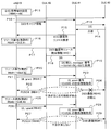
- the radio base station 10 sets frequency resources for D2D communication in advance (processing P11).
- the setting may be performed by the scheduler 111 (D2D scheduler 111A) illustrated in FIG.
- FIG. 9 illustrates a state in which ten RBs # 0 to # 9 are set as frequency resources that can be used for D2D communication as a non-limiting example.
- the frequency resource for D2D communication may be simply referred to as “D2D resource”.
- the radio base station 10 transmits resource allocation information (D2D carrier information) for D2D communication, for example, using PDSCH (processing P12).
- the PDSCH signal is generated by, for example, the PDSCH generation unit 112A illustrated in FIG. 6 and transmitted through the physical channel multiplexing unit 113, the transmission RF unit 114, and the transmission antenna 115.
- the PDSCH signal is received by the UE 20 located in the cell 100 of the radio base station 10.
- each of DUE # 1, DUE # 2, and CUE # 3 receives the PDSCH signal.
- the received PDSCH signal is demodulated by the PDSCH demodulator 231 illustrated in FIGS. 7 and 8, for example.
- DUE # 1 generates and transmits a DS by the DS generation unit 263 (see FIG. 7) in order to search for the DUE 20 that becomes a pair of D2D communication (process P13).
- the DS is received by DUE # 2 in the example of FIG.
- DUE # 2 detects the DS by DS detection section 252 (see FIG. 7)
- DS response generation section 262 generates a DS response signal and transmits it to DUE # 1 (process P14).
- the DUE # 1 forms a D2D communication pair with the transmission source DUE # 2 of the DS response signal.
- DUE # 1 transmits a D2D resource allocation request with DUE # 2 to the radio base station 10 (process P15).
- the D2D resource allocation request is transmitted on the PUSCH from the transmission antenna 214 through, for example, the scheduler 261 and the PUSCH generation unit 242 illustrated in FIG.
- the radio base station 10 receives and demodulates the D2D resource allocation request transmitted by the DUE # 1 by the PUSCH demodulator 123, and gives the demodulated D2D resource allocation request to the D2D scheduler 111A.
- the D2D scheduler 111A sends one of RB # 0 to RB # 9 (for example, RB # 1) set to the D2D communication resource to DUE # 1.
- the allocation is determined (process P16).
- the allocation of the D2D resource may be dynamic, but may be “quasi-static” in order to suppress the communication amount between the radio base station 10 and the DUE 20 as much as possible. “Quasi-static” may not be static (fixed), but may mean that it is not changed as frequently as “dynamic”.
- the radio base station 10 transmits the resource allocation information of RB # 1 to DUE # 1 using, for example, PDSCH (process P17).
- the PDSCH signal including the resource allocation information is generated by, for example, the PDSCH generation unit 112A illustrated in FIG.
- the transmission of the resource allocation information by the PDSCH signal may be regarded as an example of radio resource control (RRC).
- RRC radio resource control
- CUE # 3 that performs cellular communication with the radio base station 10 indicates that D2D communication is set as a frequency resource for UL cellular communication in the D2D carrier information received from the radio base station 10.
- DS is transmitted (process P18). The transmission of the DS may be performed periodically. However, the DS may be transmitted aperiodically.
- the DS is generated by, for example, the DS generation unit 271 illustrated in FIG. 8, and the “message” (see FIG. 5) may include the C-RNTI of CUE # 3.
- the DS transmitted by CUE # 3 is received by any of the UEs 20 located around CUE # 3.
- DUE # 1 receives the DS transmitted by CUE # 3.
- DUE # 1 When the DS detection unit 241 (see FIG. 7) detects reception of the DS, DUE # 1 decodes the received “message” of the DS and acquires (detects) the C-RNTI included in the “message”. (Process P19). DUE # 1 recognizes that CUE # 3 identified by the detected C-RNTI can be an interference source for D2D communication with DUE # 2. The detected C-RNTI is given to the PDCCH demodulator 232 (see FIG. 7), and thereafter used for demodulation of the PDCCH signal in the cellular communication of DL of CUE # 3.
- the radio base station 10 receives a transmission request for transmission permission information (UL grant) from the CUE # 3, the frequency resource that the CUE # 3 may use for UL transmission by the PUSCH scheduler 111B (see FIG. 6). Is assigned (process P20). In the example of FIG. 9, RB # 1 is assigned to CUE # 3.
- the radio base station 10 When the frequency resource RB # 1 to be allocated to CUE # 3 is determined, the radio base station 10 generates a UL grant including resource allocation information indicating RB # 1 by the UL grant generation unit 112B (see FIG. 6), for example, to PDCCH. To CUE # 3 (process P21).
- the PDCCH signal including the UL grant addressed to CUE # 3 is also received by DUE # 1 located in the cell 100 of the radio base station 10 (see FIG. 1).
- DUE # 1 tries to decode the PDCCH signal addressed to CUE # 3 by the PDCCH demodulation unit 232 (see FIG. 7) using the C-RNTI of CUE # 3 detected in process P19. If the decoding is successful, the DUE # 1 can acquire the allocation information of the frequency resource RB # 1 allocated to the CUE # 3 by the radio base station 10 for UL cellular communication (process P23).
- DUE # 1 recognizes that interference may occur when transmitting D2D communication addressed to DUE # 2 using RB # 1 assigned by radio base station 10 to CUE # 3, Transmission of D2D communication using RB # 1 is not performed (process P24). Alternatively, DUE # 1 may perform transmission addressed to DUE # 2 using another frequency resource that does not overlap with RB # 1.
- the scheduler 261 (see FIG. 7) performs scheduling of D2D data to be given to the D2D data signal generation unit 264 so that the scheduler 261 (see FIG. 7) avoids a frequency resource (RB) overlapping with RB # 1. It may be implemented by doing.
- DUE # 1 may perform transmission addressed to DUE # 2 using the D2D resource.
- DUE # 1 when the UL grant addressed to CUE # 3 indicates RB # 2, DUE # 1 does not cause interference with cellular communication if RB # 1 is used. , Transmission to DUE # 2 may be performed using RB # 1.
- DUE # 2 which forms a pair of DUE # 1 and D2D communication, also avoids using RB # 1 used for cellular communication by CUE # 3 in the same manner as the processing in DUE # 1 described above, and transmits D2D communication. Can be performed. The same applies to the DUE 20 forming another D2D communication pair.
- the DUE 20 (for example, DUE # 2) on the receiving side of the D2D communication does not include the interference component of the cellular communication or includes a data signal having sufficient quality for the D2D communication even if it includes the interference component of the cellular communication (for example, DUE # 1). ).
- the transmission side DUE 20 of D2D communication does not perform transmission using frequency resources with a low probability of being correctly received by the reception side DUE 20 even if data transmission is performed, and therefore interference with surrounding communication due to unnecessary data transmission. You can avoid giving it. In other words, the transmission side DUE 20 can be prevented from becoming an interference source for other communications.
- “Other communication” is, for example, cellular communication or another D2D communication of the CUE 20 located in the vicinity of the transmission side DUE 20.
- the frequency resource that DUE # 1 that has successfully demodulated and decoded the UL grant addressed to CUE # 3 and detected the C-RNTI of CUE # 3 autonomously uses it to transmit D2D communication.
- An example of controlling (scheduling) has been described.
- the DUE # 1 that detects the C-RNTI of the CUE # 3 notifies the radio base station 10 of the C-RNTI, thereby causing the radio base station 10 to interfere with the cellular communication and the D2D communication.
- frequency resources are scheduled to be avoided will be described.
- the interference avoidance method corresponds to a “second interference avoidance method” with respect to the “first interference avoidance method” of the first embodiment.
- the configuration examples of the radio base station 10, the DUE 20D, and the CUE 20C may be the same as the configurations illustrated in FIGS.
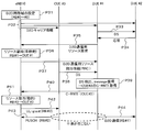
- FIG. 10 is a sequence diagram for explaining the operation (second interference avoidance method) of the wireless communication system according to the second embodiment.
- processes shown in processes P31 to P39 are the same as or similar to the processes P11 to P19 illustrated in FIG.
- the DUE # 1 succeeds in the demodulation and decoding of the PDCCH signal addressed to the CUE # 3, and the C-RNTI
- the process up to detection of the above may be the same as the first interference avoidance method described above.
- the DUE # 1 that detects the C-RNTI of the CUE # 3 notifies the radio base station 10 of the C-RNTI (may be referred to as “report”) (process P40).
- the notification may be performed on PUSCH.
- the PUSCH signal including the CUE # 3 C-RNTI may be generated by the PUSCH generation unit 242 illustrated in FIG.
- the PUSCH generation unit 242 may receive the C-RNTI of the interference source CUE # 3 detected by the DS detection unit 241 (see the dotted arrow in FIG. 7) and generate a PUSCH signal including the C-RNTI. . Therefore, the PUSCH generation unit 242 and the transmission RF unit 224 illustrated in FIG. 7 may be regarded as an example of a transmission unit that transmits identification information of the interference source CUE 20 to the radio base station 10.
- C-RNTI notification to the radio base station 10 may be performed using a UL physical channel different from the PUSCH. Further, the notification may be performed using information that allows the radio base station 10 to identify CUE # 3 instead of C-RNTI.
- the information notified to the radio base station 10 may be information that allows the radio base station 10 to identify CUE # 3 that can be an interference source of D2D communication. Therefore, unique device identification information that is permanently assigned to CUE # 3 may be used instead of C-RNTI. However, it can be said that using C-RNTI, which is temporary information, makes it easier to ensure communication security.
- the radio base station 10 When the radio base station 10 receives and demodulates the PUSCH signal including the C-RNTI of the CUE # 3, which is the transmission source of the DUE # 1, by the PUSCH demodulator 123 (see FIG. 6), the radio base station 10 transmits the C-RNTI of the CUE # 3. Is given to the scheduler 111 (for example, PUSCH scheduler 111B).
- the scheduler 111 for example, PUSCH scheduler 111B.
- the scheduler 111B Based on the C-RNTI, the scheduler 111B identifies CUE # 3 that can be an interference source for the reporter DUE # 1, and assigns a frequency resource that does not overlap with the D2D resource assigned to DUE # 1 to CUE # 3 ( Process P41).
- the scheduler 111 is an example of a control unit that controls radio resources used by the CUE # 3 identified by the C-RNTI received from the DUE # 1 for cellular communication with the radio base station 10 to resources that do not overlap with the D2D resources. You may think that it is.
- radio base station 10 When allocation of RB # 2 to CUE # 3 is determined, radio base station 10 generates UL grant including resource allocation information indicating RB # 2 by UL grant generation unit 112B and transmits it on PDCCH (process P42) .
- CUE # 3 When CUE # 3 receives and demodulates the UL grant from radio base station 10 in PDCCH demodulation section 232 (see FIG. 8), CUE # 3 recognizes that RB # 2 has been assigned to PUSCH transmission. The PUSCH is transmitted (process P43).
- the DUE 20 (for example, DUE # 2) on the receiving side of the D2D communication does not include the interference component of the cellular communication or includes a data signal having sufficient quality for the D2D communication even if it includes the interference component of the cellular communication (for example, DUE # 1). ) Can be received.
- the DUE # 2 that forms a pair of DUE # 1 and D2D communication detects the C-RNTI of the CUE # 3 that can be an interference source in the same manner as the processing in the DUE # 1 described above, and sends it to the radio base station 10. You may report it. The same applies to the DUE 20 forming another D2D communication pair.
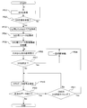
- a third embodiment (third interference avoiding method) will be described with reference to the flowchart illustrated in FIG.
- the DUE 20 receives and detects the DS transmitted by the CUE 20
- the D2D communication is temporarily stopped regardless of which frequency resource is assigned to which communication by the radio base station 10.
- the configuration examples of the radio base station 10, the DUE 20D, and the CUE 20C may be the same as the configurations illustrated in FIGS.
- the DUE 20 uses the DS generation unit 263 (see FIG. 7) as a DS for searching for another DUE 20 that forms a D2D communication pair. Is generated and transmitted (process P51).
- DUE # 1 periodically repeats DS transmission until receiving a DS response signal (until determined as Yes in process P52) (No route in process P52).
- the DUE # 1 receives the DUE 20 (for example, FIGS. 1 and 5) that is the transmission source of the DS response signal. Are formed as a pair of DUE # 2) and D2D communication (process P53).
- DUE # 1 transmits a D2D resource allocation request to the radio base station 10 using, for example, PUSCH (process P54).
- the PUSCH signal is generated by, for example, the PUSCH generation unit 242 illustrated in FIG.
- DUE # 1 receives D2D resource allocation information from the radio base station 10, for example, by PDSCH (processing P55). Thereafter, DUE # 1 monitors whether or not the DS transmitted by CUE 20 (for example, CUE # 3 in FIG. 5) is received (processing P56 and P57).
- DUE # 1 waits for a certain period of time to transmit D2D communication (processing P58). ), The reception monitoring of the DS transmitted by the CUE 20 is continued.
- the “certain time” may illustratively be a time on the order of milliseconds.
- the time to wait after detecting the reception of the DS does not necessarily have to be a fixed time and may be variable.
- the standby time may be made variable according to the moving speed of DUE # 1 that has detected the reception of DS. As a non-limiting example, it is considered that the slower the moving speed of DUE # 1, the less the environment changes that are likely to cause interference, so the standby time may be lengthened.
- DUE # 1 If reception of the DS transmitted by CUE 20 is not detected (No in process P57), DUE # 1 transmits a D2D data signal using the frequency resource indicated by the D2D resource allocation information received in process P55 ( Process P59).
- DUE # 1 ends the process when there is no untransmitted D2D data signal addressed to DUE # 2 (No in process P60). On the other hand, if an untransmitted D2D data signal addressed to DUE # 2 remains (Yes in process P60), DUE # 1 checks whether or not the current timing corresponds to the DS transmission timing by CUE20. (Process P61).
- DUE # 1 may store information indicating the timing (for example, the cycle) at which the CUE 20 transmits a DS (hereinafter also referred to as “CUE-DS transmission timing information”).
- the CUE-DS transmission timing information may be set and stored in advance in the DUE 20 as known information with the CUE 20, or may be notified from the CUE 20 (or the radio base station 10).
- DUE # 1 continues transmission until there is no D2D data signal addressed to DUE # 2 To do.
- the DUE # 1 returns to the process P56 and monitors whether or not the DS is received from the CUE 20.
- DUE # 2 that forms a pair of DUE # 1 and D2D communication may also perform the same processes P51 to P61 as described above.
- the D2D communication is temporarily stopped regardless of which frequency resource is assigned to which communication by the radio base station 10. Interference with D2D communication can be avoided.
- the receiving side DUE 20 (for example, DUE # 2) of the D2D communication can receive a data signal of sufficient quality when the transmitting side DUE 20 (for example, DUE # 1) transmits the D2D data signal.
- the transmission side DUE 20 of the D2D communication does not perform transmission at a timing with a low probability of being correctly received by the reception side DUE 20 even if data transmission is performed, peripheral cellular communication or other D2D is performed by unnecessary data transmission. Interference can be avoided in communication.
- the DUE # 1 that has detected the DS from the CUE # 3 monitors again whether or not the DS is received from the CUE # 3 (or another CUE 20) after waiting for a predetermined time. Yes.
- the DUE 20 may attempt to transmit D2D communication without performing DS reception monitoring after waiting for a predetermined time. This is because interference may not occur even if transmission of D2D communication is performed as time elapses after DS is detected.
- the DUE 20 temporarily stops the D2D communication in response to detection of reception of the DS transmitted by the CUE 20, but in the fourth embodiment, the number of received and detected DSs is a predetermined value (for example, The D2D communication may be temporarily stopped after becoming an integer of 2 or more.
- the DUE 20 tries to avoid the frequency resource allocated to the CUE 20 by trying to decode the UL grant addressed to the CUE 20 as in the first embodiment until the number of received and detected DSs reaches a predetermined value. D2D communication may be performed.
- the configuration examples of the radio base station 10, the DUE 20D, and the CUE 20C may be the same as the configurations illustrated in FIGS.
- the DUE 20 (for example, DUE # 1) transmits a pair of D2D communication with another DUE 20 (for example, DUE # 2) in the same manner as in the third embodiment, and then the CUE 20 transmits It is monitored whether or not the received DS is received and detected (processes P71 to P77).
- the DUE # 1 checks whether or not the number of DSs detected to be received within a predetermined time (hereinafter referred to as “DS reception number”) is equal to or greater than a predetermined value (processing P77). Process P78 from Yes route).
- the “predetermined time” may be set to a time shorter than the DS transmission cycle by the CUE 20, for example.
- a predetermined value (in other words, a threshold value) regarding the number of DS receptions may be stored in a memory (not shown) provided in DUE # 1.
- the memory may be provided in, for example, the scheduler 261 illustrated in FIG.
- DUE # 1 waits for a certain period of time for D2D communication with DUE # 2 (process P79), and DS is received and detected from CUE20. Continue monitoring whether or not.
- DUE # 1 receives CUE 20 that can be an interference source of D2D communication from the received “message” (see FIG. 5) (for example, , CUE # 3) C-RNTI is detected and acquired (process P80).
- DUE # 1 When detecting the C-RNTI of CUE # 3, DUE # 1 tries to demodulate and decode the UL grant transmitted from the radio base station 10 on the PDCCH addressed to CUE # 3 using the C-RNTI.
- DUE # 1 stores the resource allocation information indicated by the UL grant.
- the resource allocation information may be stored in the memory described above. If resource allocation information is already stored in the memory, DUE # 1 may update the resource allocation information (hereinafter also referred to as “accumulated information”) to the resource allocation information indicated by the latest UL grant (processing) P82).
- DUE # 1 refers to the accumulated information of the resource allocation information allocated to CUE20 (process P83), and the frequency indicated by the D2D resource allocated from radio base station 10 in process P75 and the UL grant addressed to CUE # 3 Check for overlap with resources (process P84). For example, DUE # 1 checks whether or not the resource duplication occurs at the transmission timing of the data signal (for example, subframe) of D2D communication.
- DUE # 1 transmits a D2D data signal using the frequency resource indicated by the D2D resource allocation information received in process P75, as in the third embodiment. Perform (Process P85).
- DUE # 1 ends the process when there is no untransmitted D2D data signal addressed to DUE # 2 (No in process P86). On the other hand, if an untransmitted D2D data signal addressed to DUE # 2 remains (Yes in process P86), DUE # 1 determines that the current timing is the same as the DS transmission timing by CUE20, as in the third embodiment. It is checked whether or not it corresponds (process P87).
- the DUE # 1 returns to the process P83, and stores the accumulated information of the resource allocation information of the CUE 20 Refer to it and check for duplicate resources.
- the DUE # 1 returns to the process P76 and monitors whether or not the DS is received from the CUE 20.
- the DUE # 1 when the UL grant addressed to the CUE # 3 fails to be decoded (No in the process P81), the DUE # 1 performs the processes P83 to P87. For example, DUE # 1 may perform resource duplication check based on past accumulated information of resource allocation information allocated to CUE 20 to determine whether or not D2D communication is possible.
- the DUE # 1 checks whether or not the current timing corresponds to the DS transmission timing by the CUE 20 ( Process P87).
- the DUE # 1 returns to the process P83 and refers to the resource allocation information accumulation information of the CUE 20 to refer to the resource Check for duplicates.
- the DUE # 1 may proceed to the process after the process P83.
- DUE # 2 that forms a pair of DUE # 1 and D2D communication may perform the same processes P71 to P87 as described above.
- the DUE 20 stops the D2D communication if the number of DS reception from the CUE 20 is equal to or greater than the predetermined value, and if the number of DS reception is less than the predetermined value, the DUE 20 D2D communication can be performed avoiding the use of allocated frequency resources.
- the DUE 20 can avoid interference between cellular communication and D2D communication by not performing D2D communication. In addition, it is possible to avoid interference with neighboring cellular communications and other D2D communications due to unnecessary data transmission by the DUE 20.
- the DUE 20 can perform D2D communication by avoiding the use of the frequency resources allocated to the CUE 20. Can be used.
- the receiving side DUE 20 for example, DUE # 2 of the D2D communication can receive a data signal with sufficient quality from the transmitting side DUE 20 (for example, DUE # 1).
- the radio base station 10 may allocate radio resources other than radio resources for D2D communication.
- the radio base station 10 allocates radio resources other than radio resources for D2D communication to the CUE 20 Just do it.
- the radio base station 10 may allocate radio resources other than the radio resources for D2D communication to the CUE 20 that moves at high speed.
- the radio base station 10 may control whether or not the DS can be transmitted from the CUE 20 according to the moving speed of the CUE 20. For example, for the CUE 20 that moves at a high speed at a speed exceeding a certain speed threshold, it is possible to save radio resources used for the DS transmission and reduce the power consumption of the CUE 20 by stopping the DS transmission.
- radio resources for example, frequency resources
- System capacity can be increased.
- the wireless communication performance can be improved.
- the UL frequency resource is used as an example of a radio resource shared by cellular communication and D2D communication (in other words, interference may occur). It may be a time resource.
Abstract
Priority Applications (6)
| Application Number | Priority Date | Filing Date | Title |
|---|---|---|---|
| JP2016528732A JP6456949B2 (ja) | 2014-06-19 | 2014-06-19 | 無線通信システム、無線通信方法、無線機器、及び、無線基地局 |
| CN201480079953.XA CN106465396A (zh) | 2014-06-19 | 2014-06-19 | 无线通信系统、无线通信方法、无线设备以及无线基站 |
| EP14895322.7A EP3160204A4 (fr) | 2014-06-19 | 2014-06-19 | Système de communication sans fil, procédé de communication sans fil, dispositif sans fil et station de base sans fil |
| PCT/JP2014/066341 WO2015194014A1 (fr) | 2014-06-19 | 2014-06-19 | Système de communication sans fil, procédé de communication sans fil, dispositif sans fil et station de base sans fil |
| KR1020167034431A KR20170003978A (ko) | 2014-06-19 | 2014-06-19 | 무선 통신 시스템, 무선 통신 방법, 무선 기기 및 무선 기지국 |
| US15/373,097 US20170094653A1 (en) | 2014-06-19 | 2016-12-08 | Wireless communication system, wireless communication method, wireless device, and wireless base station |
Applications Claiming Priority (1)
| Application Number | Priority Date | Filing Date | Title |
|---|---|---|---|
| PCT/JP2014/066341 WO2015194014A1 (fr) | 2014-06-19 | 2014-06-19 | Système de communication sans fil, procédé de communication sans fil, dispositif sans fil et station de base sans fil |
Related Child Applications (1)
| Application Number | Title | Priority Date | Filing Date |
|---|---|---|---|
| US15/373,097 Continuation US20170094653A1 (en) | 2014-06-19 | 2016-12-08 | Wireless communication system, wireless communication method, wireless device, and wireless base station |
Publications (1)
| Publication Number | Publication Date |
|---|---|
| WO2015194014A1 true WO2015194014A1 (fr) | 2015-12-23 |
Family
ID=54935043
Family Applications (1)
| Application Number | Title | Priority Date | Filing Date |
|---|---|---|---|
| PCT/JP2014/066341 WO2015194014A1 (fr) | 2014-06-19 | 2014-06-19 | Système de communication sans fil, procédé de communication sans fil, dispositif sans fil et station de base sans fil |
Country Status (6)
| Country | Link |
|---|---|
| US (1) | US20170094653A1 (fr) |
| EP (1) | EP3160204A4 (fr) |
| JP (1) | JP6456949B2 (fr) |
| KR (1) | KR20170003978A (fr) |
| CN (1) | CN106465396A (fr) |
| WO (1) | WO2015194014A1 (fr) |
Cited By (2)
| Publication number | Priority date | Publication date | Assignee | Title |
|---|---|---|---|---|
| WO2017135453A1 (fr) * | 2016-02-04 | 2017-08-10 | 株式会社Nttドコモ | Dispositif utilisateur, station de base, procédé d'identification de canal, et procédé d'identification de canal |
| WO2018130151A1 (fr) * | 2017-01-10 | 2018-07-19 | Mediatek Inc. | Conception de canal de commande en liaison descendante physique pour une nouvelle radio 5g |
Families Citing this family (1)
| Publication number | Priority date | Publication date | Assignee | Title |
|---|---|---|---|---|
| WO2014050887A1 (fr) * | 2012-09-27 | 2014-04-03 | 京セラ株式会社 | Système de communication mobile, terminal utilisateur, station de base et processeur |
Citations (4)
| Publication number | Priority date | Publication date | Assignee | Title |
|---|---|---|---|---|
| JP2009523377A (ja) * | 2006-01-11 | 2009-06-18 | クゥアルコム・インコーポレイテッド | ビーコン信号を介して優先順位情報を送信するための通信方法および装置 |
| US20120028672A1 (en) * | 2010-07-30 | 2012-02-02 | Tao Chen | Apparatus and Method for Transmitter Power Control for Device-to-Device Communications in a Communication System |
| US20120300662A1 (en) * | 2010-01-22 | 2012-11-29 | Nokia Corporation | Cellular Control Sensing for Multicell Device-to-Device Interference Control |
| JP2013153484A (ja) * | 2007-07-10 | 2013-08-08 | Qualcomm Inc | 周波数スペクトルを共有するネットワーク間の干渉管理のための方法および装置 |
Family Cites Families (16)
| Publication number | Priority date | Publication date | Assignee | Title |
|---|---|---|---|---|
| US9614641B2 (en) * | 2010-05-12 | 2017-04-04 | Qualcomm Incorporated | Resource coordination for peer-to-peer groups through distributed negotiation |
| US8401562B2 (en) * | 2010-11-17 | 2013-03-19 | Nokia Corporation | Apparatus and method employing scheduler behavior aware predictive resource selection in a communication system |
| JP5763835B2 (ja) * | 2011-04-19 | 2015-08-12 | テレフオンアクチーボラゲット エル エム エリクソン(パブル) | 干渉を処理し及び無線リソースを適宜スケジューリングするための無線基地局及び無線基地局における方法 |
| DE112011105271T5 (de) * | 2011-05-25 | 2014-03-06 | Renesas Mobile Corporation | Ressourcenzuordnung für eine D2D-Kommunikation |
| KR102138532B1 (ko) * | 2012-06-22 | 2020-07-28 | 엘지전자 주식회사 | 기기-대-기기 통신을 위한 스케줄링 방법 및 이를 위한 장치 |
| JPWO2014017479A1 (ja) * | 2012-07-27 | 2016-07-11 | 京セラ株式会社 | 移動通信システム、移動通信方法、無線端末及び無線基地局 |
| JP5886968B2 (ja) * | 2012-08-28 | 2016-03-16 | 京セラ株式会社 | 基地局、ユーザ端末及びプロセッサ |
| WO2014034286A1 (fr) * | 2012-08-29 | 2014-03-06 | 京セラ株式会社 | Système de communication mobile, station de base, terminal utilisateur et processeur |
| KR102012734B1 (ko) * | 2012-09-25 | 2019-08-21 | 한국전자통신연구원 | 셀룰러 이동통신 기반 단말간 직접 통신에서 링크 적응 송수신 방법 |
| WO2014070058A1 (fr) * | 2012-11-05 | 2014-05-08 | Telefonaktiebolaget L M Ericsson (Publ) | Découverte de voisins dans des communications de dispostitif à dispositif |
| US9516659B2 (en) * | 2012-12-06 | 2016-12-06 | Intel Corporation | Carrier type (NCT) information embedded in synchronization signal |
| WO2015005601A1 (fr) * | 2013-07-10 | 2015-01-15 | 엘지전자 주식회사 | Procédé de régulation de puissance pour la communication de dispositif à dispositif (d2d) dans un système de communication sans fil, et appareil correspondant |
| CN103415022A (zh) * | 2013-08-12 | 2013-11-27 | 电子科技大学 | 基站控制下的d2d频谱分配方法 |
| US20170244525A1 (en) * | 2014-05-08 | 2017-08-24 | Fujitsu Limited | Resource allocation |
| CN106465313B (zh) * | 2014-06-17 | 2020-02-11 | Lg电子株式会社 | 无线通信系统中接收用于终端之间直接通信的同步信号的方法及其装置 |
| EP3160203A4 (fr) * | 2014-06-19 | 2018-01-24 | Fujitsu Limited | Système de communications sans fil, procédé de communications sans fil, dispositif sans fil, et station de base sans fil |
-
2014
- 2014-06-19 EP EP14895322.7A patent/EP3160204A4/fr not_active Withdrawn
- 2014-06-19 WO PCT/JP2014/066341 patent/WO2015194014A1/fr active Application Filing
- 2014-06-19 CN CN201480079953.XA patent/CN106465396A/zh active Pending
- 2014-06-19 JP JP2016528732A patent/JP6456949B2/ja not_active Expired - Fee Related
- 2014-06-19 KR KR1020167034431A patent/KR20170003978A/ko active IP Right Grant
-
2016
- 2016-12-08 US US15/373,097 patent/US20170094653A1/en not_active Abandoned
Patent Citations (6)
| Publication number | Priority date | Publication date | Assignee | Title |
|---|---|---|---|---|
| JP2009523377A (ja) * | 2006-01-11 | 2009-06-18 | クゥアルコム・インコーポレイテッド | ビーコン信号を介して優先順位情報を送信するための通信方法および装置 |
| JP2012029303A (ja) * | 2006-01-11 | 2012-02-09 | Qualcomm Inc | 標識符号を使用する無線通信方法及び装置 |
| JP2013219802A (ja) * | 2006-01-11 | 2013-10-24 | Qualcomm Inc | ワイドエリアネットワークとローカルエリアピア・ツー・ピアネットワークとの間で帯域幅を共有するための方法および装置 |
| JP2013153484A (ja) * | 2007-07-10 | 2013-08-08 | Qualcomm Inc | 周波数スペクトルを共有するネットワーク間の干渉管理のための方法および装置 |
| US20120300662A1 (en) * | 2010-01-22 | 2012-11-29 | Nokia Corporation | Cellular Control Sensing for Multicell Device-to-Device Interference Control |
| US20120028672A1 (en) * | 2010-07-30 | 2012-02-02 | Tao Chen | Apparatus and Method for Transmitter Power Control for Device-to-Device Communications in a Communication System |
Non-Patent Citations (2)
| Title |
|---|
| CATR: "Coexistence issues between D2D discovery and WAN", 3GPP TSG RAN WG1 MEETING #77 R1- 142361, 19 May 2014 (2014-05-19), XP050787955 * |
| See also references of EP3160204A4 * |
Cited By (7)
| Publication number | Priority date | Publication date | Assignee | Title |
|---|---|---|---|---|
| WO2017135453A1 (fr) * | 2016-02-04 | 2017-08-10 | 株式会社Nttドコモ | Dispositif utilisateur, station de base, procédé d'identification de canal, et procédé d'identification de canal |
| EP3413616A4 (fr) * | 2016-02-04 | 2019-08-07 | Ntt Docomo, Inc. | Dispositif utilisateur, station de base, procédé d'identification de canal, et procédé d'identification de canal |
| WO2018130151A1 (fr) * | 2017-01-10 | 2018-07-19 | Mediatek Inc. | Conception de canal de commande en liaison descendante physique pour une nouvelle radio 5g |
| CN109314952A (zh) * | 2017-01-10 | 2019-02-05 | 联发科技股份有限公司 | 第五代新无线电物理下行控制信道设计 |
| US10440703B2 (en) | 2017-01-10 | 2019-10-08 | Mediatek Inc. | Physical downlink control channel design for 5G new radio |
| US10785769B2 (en) | 2017-01-10 | 2020-09-22 | Mediatek Inc. | Physical downlink control channel design for 5G new radio |
| CN109314952B (zh) * | 2017-01-10 | 2023-05-30 | 联发科技股份有限公司 | 新无线电物理下行控制信道设计的方法及其发送设备 |
Also Published As
| Publication number | Publication date |
|---|---|
| JP6456949B2 (ja) | 2019-01-23 |
| KR20170003978A (ko) | 2017-01-10 |
| CN106465396A (zh) | 2017-02-22 |
| JPWO2015194014A1 (ja) | 2017-04-20 |
| US20170094653A1 (en) | 2017-03-30 |
| EP3160204A1 (fr) | 2017-04-26 |
| EP3160204A4 (fr) | 2018-01-24 |
Similar Documents
| Publication | Publication Date | Title |
|---|---|---|
| JP7254714B2 (ja) | 端末、無線通信方法、基地局及びシステム | |
| WO2016182052A1 (fr) | Terminal utilisateur, station de base sans fil et procédé de communication sans fil | |
| WO2018061521A1 (fr) | Dispositif et procédé de communication | |
| KR101925195B1 (ko) | Lte 네트워크에서의 패킷 기반 장치 대 장치(d2d) 탐색을 위한 사용자 장비 및 방법 | |
| WO2017191832A1 (fr) | Terminal d'utilisateur et procédé de communication sans fil | |
| WO2017195848A1 (fr) | Terminal utilisateur, et procédé de communication sans fil | |
| WO2017165140A1 (fr) | Transmissions sans fil autonomes | |
| US20180115980A1 (en) | Signalling for group communications | |
| US20170094673A1 (en) | Wireless communication system, wireless communication method, wireless device, and wireless base station | |
| JP6446375B2 (ja) | 移動通信システム及びユーザ端末 | |
| CN106465474B (zh) | 用户装置以及信号接收方法 | |
| US11399387B2 (en) | System and method for scheduling for redundant layer 2 control messages | |
| JP6456949B2 (ja) | 無線通信システム、無線通信方法、無線機器、及び、無線基地局 | |
| US11496951B2 (en) | Mobile communication system and radio terminal | |
| WO2015115003A1 (fr) | Terminal d'utilisateur, système de communications sans fil et procédé de communications sans fil | |
| WO2019087361A1 (fr) | Équipement d'utilisateur, et procédé de communication sans fil | |
| EP3454488B1 (fr) | Procédé et dispositif pour surveiller un canal de commande | |
| JPWO2016121871A1 (ja) | 基地局及びユーザ装置 | |
| WO2015194016A1 (fr) | Système de communication sans fil, procédé de communication sans fil, station de base sans fil et dispositif sans fil | |
| JP2023501232A (ja) | インターレースリソース割振りのための半永続的スケジューリング非アクティブ化 | |
| WO2018083779A1 (fr) | Système de communication sans fil, station de base, dispositif sans fil, et procédé de communication sans fil | |
| CN116848915A (zh) | 寻呼响应之后的快速信令释放解决方案 |
Legal Events
| Date | Code | Title | Description |
|---|---|---|---|
| 121 | Ep: the epo has been informed by wipo that ep was designated in this application |
Ref document number: 14895322 Country of ref document: EP Kind code of ref document: A1 |
|
| ENP | Entry into the national phase |
Ref document number: 2016528732 Country of ref document: JP Kind code of ref document: A |
|
| ENP | Entry into the national phase |
Ref document number: 20167034431 Country of ref document: KR Kind code of ref document: A |
|
| REEP | Request for entry into the european phase |
Ref document number: 2014895322 Country of ref document: EP |
|
| WWE | Wipo information: entry into national phase |
Ref document number: 2014895322 Country of ref document: EP |
|
| NENP | Non-entry into the national phase |
Ref country code: DE |