WO2017195848A1 - Terminal utilisateur, et procédé de communication sans fil - Google Patents
Terminal utilisateur, et procédé de communication sans fil Download PDFInfo
- Publication number
- WO2017195848A1 WO2017195848A1 PCT/JP2017/017771 JP2017017771W WO2017195848A1 WO 2017195848 A1 WO2017195848 A1 WO 2017195848A1 JP 2017017771 W JP2017017771 W JP 2017017771W WO 2017195848 A1 WO2017195848 A1 WO 2017195848A1
- Authority
- WO
- WIPO (PCT)
- Prior art keywords
- transmission
- resource
- data
- user terminal
- collision
- Prior art date
Links
- 238000004891 communication Methods 0.000 title claims description 61
- 238000000034 method Methods 0.000 title claims description 41
- 230000005540 biological transmission Effects 0.000 claims abstract description 222
- 238000012545 processing Methods 0.000 claims description 88
- 230000011664 signaling Effects 0.000 claims description 56
- 238000005259 measurement Methods 0.000 description 22
- 230000007274 generation of a signal involved in cell-cell signaling Effects 0.000 description 18
- 238000010586 diagram Methods 0.000 description 17
- 238000013507 mapping Methods 0.000 description 17
- 238000003860 storage Methods 0.000 description 9
- 230000006870 function Effects 0.000 description 7
- 230000004044 response Effects 0.000 description 7
- 238000005516 engineering process Methods 0.000 description 5
- 238000007726 management method Methods 0.000 description 5
- 238000010295 mobile communication Methods 0.000 description 4
- 230000008569 process Effects 0.000 description 4
- 125000004122 cyclic group Chemical group 0.000 description 3
- 101000741965 Homo sapiens Inactive tyrosine-protein kinase PRAG1 Proteins 0.000 description 2
- 102100038659 Inactive tyrosine-protein kinase PRAG1 Human genes 0.000 description 2
- 230000002776 aggregation Effects 0.000 description 2
- 238000004220 aggregation Methods 0.000 description 2
- 238000012937 correction Methods 0.000 description 2
- 230000008878 coupling Effects 0.000 description 2
- 238000010168 coupling process Methods 0.000 description 2
- 238000005859 coupling reaction Methods 0.000 description 2
- 238000013461 design Methods 0.000 description 2
- 238000001514 detection method Methods 0.000 description 2
- 230000007774 longterm Effects 0.000 description 2
- 239000013307 optical fiber Substances 0.000 description 2
- 230000009467 reduction Effects 0.000 description 2
- 238000013468 resource allocation Methods 0.000 description 2
- 206010042135 Stomatitis necrotising Diseases 0.000 description 1
- 230000006978 adaptation Effects 0.000 description 1
- 239000000969 carrier Substances 0.000 description 1
- 239000003795 chemical substances by application Substances 0.000 description 1
- 230000009977 dual effect Effects 0.000 description 1
- 239000000835 fiber Substances 0.000 description 1
- 230000010354 integration Effects 0.000 description 1
- 239000006249 magnetic particle Substances 0.000 description 1
- 238000004519 manufacturing process Methods 0.000 description 1
- 230000004048 modification Effects 0.000 description 1
- 238000012986 modification Methods 0.000 description 1
- 201000008585 noma Diseases 0.000 description 1
- 230000002093 peripheral effect Effects 0.000 description 1
- 230000010363 phase shift Effects 0.000 description 1
- 230000011218 segmentation Effects 0.000 description 1
- 238000000926 separation method Methods 0.000 description 1
- 238000004904 shortening Methods 0.000 description 1
- 230000007704 transition Effects 0.000 description 1
Images


Classifications
-
- H—ELECTRICITY
- H04—ELECTRIC COMMUNICATION TECHNIQUE
- H04W—WIRELESS COMMUNICATION NETWORKS
- H04W72/00—Local resource management
- H04W72/02—Selection of wireless resources by user or terminal
-
- H—ELECTRICITY
- H04—ELECTRIC COMMUNICATION TECHNIQUE
- H04W—WIRELESS COMMUNICATION NETWORKS
- H04W72/00—Local resource management
- H04W72/20—Control channels or signalling for resource management
- H04W72/23—Control channels or signalling for resource management in the downlink direction of a wireless link, i.e. towards a terminal
-
- H—ELECTRICITY
- H04—ELECTRIC COMMUNICATION TECHNIQUE
- H04B—TRANSMISSION
- H04B1/00—Details of transmission systems, not covered by a single one of groups H04B3/00 - H04B13/00; Details of transmission systems not characterised by the medium used for transmission
- H04B1/69—Spread spectrum techniques
- H04B1/713—Spread spectrum techniques using frequency hopping
- H04B1/7143—Arrangements for generation of hop patterns
-
- H—ELECTRICITY
- H04—ELECTRIC COMMUNICATION TECHNIQUE
- H04W—WIRELESS COMMUNICATION NETWORKS
- H04W72/00—Local resource management
- H04W72/12—Wireless traffic scheduling
-
- H—ELECTRICITY
- H04—ELECTRIC COMMUNICATION TECHNIQUE
- H04W—WIRELESS COMMUNICATION NETWORKS
- H04W74/00—Wireless channel access
- H04W74/08—Non-scheduled access, e.g. ALOHA
- H04W74/0833—Random access procedures, e.g. with 4-step access
-
- H—ELECTRICITY
- H04—ELECTRIC COMMUNICATION TECHNIQUE
- H04W—WIRELESS COMMUNICATION NETWORKS
- H04W80/00—Wireless network protocols or protocol adaptations to wireless operation
- H04W80/02—Data link layer protocols
-
- H—ELECTRICITY
- H04—ELECTRIC COMMUNICATION TECHNIQUE
- H04W—WIRELESS COMMUNICATION NETWORKS
- H04W72/00—Local resource management
- H04W72/04—Wireless resource allocation
- H04W72/044—Wireless resource allocation based on the type of the allocated resource
- H04W72/0453—Resources in frequency domain, e.g. a carrier in FDMA
-
- H—ELECTRICITY
- H04—ELECTRIC COMMUNICATION TECHNIQUE
- H04W—WIRELESS COMMUNICATION NETWORKS
- H04W74/00—Wireless channel access
- H04W74/08—Non-scheduled access, e.g. ALOHA
Definitions
- the present invention relates to a user terminal and a wireless communication method in a next generation mobile communication system.
- LTE Long Term Evolution
- Non-Patent Document 1 LTE-A (LTE-Advanced), FRA (Future Radio Access), 4G, 5G, 5G + (plus), NR ( New RAT) and LTE Rel.14, 15 ⁇ ) are also being considered.
- an existing LTE system for example, LTE Rel. 8-13
- UL synchronization when UL synchronization is established between a radio base station and a user terminal, UL data can be transmitted from the user terminal.
- the existing LTE system supports a random access procedure (RACH procedure: Random Access Channel Procedure, also referred to as access procedure) for establishing UL synchronization.
- RACH procedure Random Access Channel Procedure, also referred to as access procedure
- the user terminal sends information on the UL transmission timing (timing advance (TA)) with a response (random access response) from the radio base station to a randomly selected preamble (random access preamble). Acquire and establish UL synchronization based on the TA.
- timing advance TA
- random access response random access response
- the user terminal After the UL synchronization is established, the user terminal receives downlink control information (DCI: Downlink Control Information) (UL grant) from the radio base station, and then transmits UL data using the UL resource allocated by the UL grant. To do.
- DCI Downlink Control Information
- UL grant Downlink Control Information
- E-UTRA Evolved Universal Terrestrial Radio Access
- E-UTRAN Evolved Universal Terrestrial Radio Access Network
- a collision of UL transmissions of a plurality of user terminals is allowed and a radio base station Transmission of UL data without UL grant (collision-type UL transmission (Contention-based UL transmission), UL grant-less (free) UL transmission, UL grant-less and collision-type UL transmission, etc.) has been studied.
- the present invention has been made in view of such a point, and an object thereof is to provide a user terminal and a wireless communication method capable of appropriately controlling a resource area for collision-type UL transmission.
- a user terminal includes a transmission unit that transmits UL data without an uplink (UL) grant from a radio base station, and a control unit that controls transmission of the UL data,
- the control unit sets a plurality of resource areas having different parameters, and selects a resource area used for transmitting the UL data from the plurality of resource areas.
- the resource area for collision-type UL transmission can be appropriately controlled.
- Random access procedures are also referred to as collision-type random access (CBRA: Contention-Based Random Access, etc.) and non-collision-type random access (Non-CBRA, contention-free random access (CFRA), etc. )
- CBRA collision-type random access
- Non-CBRA contention-free random access
- CBRA collision type random access
- a user terminal selects a preamble randomly selected from a plurality of preambles (also referred to as a random access preamble, a random access channel (PRACH), a RACH preamble, etc.) defined in each cell.
- Collision-type random access is a random access procedure led by a user terminal, and can be used, for example, at the time of initial access or at the start or restart of UL transmission.
- Non-collision type random access (Non-CBRA, CFRA: Contention-Free Random Access)
- the radio base station uses a downlink (DL) control channel (PDCCH: Physical Downlink Control Channel, EPDCCH: Enhanced PDCCH, etc.) as a preamble. Is uniquely assigned to the user terminal, and the user terminal transmits the preamble assigned by the radio base station.
- Non-collision type random access is a network-initiated random access procedure, and can be used, for example, at the time of handover, when DL transmission is started or restarted (when transmission of DL retransmission instruction information is started or restarted in UL), etc. .
- FIG. 1 is a diagram showing an example of collision-type random access.
- a user terminal uses a random access channel (for example, MIB (Mater Information Block) and / or SIB (System Information Block)) or higher layer signaling (for example, RRC (Radio Resource Control) signaling).
- Information PRACH configuration information
- PRACH configuration indicating a PRACH configuration (PRACH configuration, RACH configuration) is received in advance.
- the PRACH configuration information includes, for example, a plurality of preambles (for example, preamble format) defined for each cell, time resources (for example, system frame number, subframe number) used for PRACH transmission, and frequency resources (for example, 6 resource blocks) (PRB: offset (prach-FrequencyOffset) indicating the start position of Physical Resource Block) can be indicated.
- preamble format for example, preamble format
- time resources for example, system frame number, subframe number
- frequency resources for example, 6 resource blocks
- PRB offset (prach-FrequencyOffset) indicating the start position of Physical Resource Block
- the radio base station When the radio base station detects the preamble, it transmits a random access response (RAR: Random Access Response) as a response (message 2).
- RAR Random Access Response
- the user terminal fails to receive the RAR within a predetermined period (RAR window) after transmitting the preamble, the user terminal increases the transmission power of the PRACH and transmits (retransmits) the preamble again. Note that increasing the transmission power during retransmission is also called power ramping.
- the user terminal that has received the RAR adjusts the UL transmission timing based on the timing advance (TA) included in the RAR, and establishes UL synchronization.
- the user terminal transmits a control message of a higher layer (L2 / L3: Layer 2 / Layer 3) using a UL resource specified by the UL grant included in the RAR (message 3).
- the control message includes a user terminal identifier (UE-ID).
- the identifier of the user terminal may be, for example, C-RNTI (Cell-Radio Network Temporary Identifier) in the RRC connection state, or S-TMSI (System Architecture Evolution-Temporary Mobile in the idle state). It may be a higher-layer UE-ID such as (Subscriber Identity).
- the radio base station transmits a collision resolution message in response to the upper layer control message (message 4).
- the collision resolution message is transmitted based on the user terminal identifier included in the control message.
- the user terminal that has successfully detected the collision resolution message transmits an acknowledgment (ACK: Acknowledge) in HARQ (Hybrid Automatic Repeat reQuest) to the radio base station. Thereby, the user terminal in an idle state transits to the RRC connection state.
- ACK Acknowledge
- HARQ Hybrid Automatic Repeat reQuest
- the user terminal that failed to detect the collision resolution message determines that a collision has occurred, reselects the preamble, and repeats the random access procedure of messages 1 to 4.
- the radio base station When the radio base station detects that the collision has been resolved by the ACK from the user terminal, the radio base station transmits a UL grant to the user terminal.
- the user terminal starts UL data using the UL resource allocated by the UL grant.
- the random access procedure can be started autonomously.
- UL data is transmitted using UL resources allocated to the user terminal by the UL grant after UL synchronization is established, highly reliable UL transmission is possible.
- a large number of connections e.g., a high-capacity communication (eMBB), a device (user terminal) for communication between devices (M2M) such as IoT and MTC (user terminal)
- M2M devices
- IoT devices
- MTC user terminal
- URLLC highly reliable communication
- FIG. 2 is a diagram illustrating an example of collision-type UL transmission.
- the user terminal uses configuration information (CBUL configuration) related to collision-type UL (CBUL) transmission based on system information (for example, MIB and / or SIB) and higher layer signaling (for example, RRC signaling). Information) may be received in advance.
- CBUL configuration configuration information related to collision-type UL (CBUL) transmission based on system information (for example, MIB and / or SIB) and higher layer signaling (for example, RRC signaling).
- system information for example, MIB and / or SIB
- RRC signaling for example, RRC signaling
- the user terminal starts transmitting UL data without receiving the UL grant from the radio base station. Specifically, when transmitting the UL data at a new UL transmission opportunity, the user terminal may transmit the preamble and the control information of the UL data together with the UL data. Further, the user terminal may transmit the control information and UL data without a response from the radio base station to the preamble.
- the preamble is used for detection of UL transmission at the radio base station.
- the radio base station can detect the UL transmission at a new UL data transmission opportunity.
- the preamble sequence may be randomly selected from a plurality of sequences indicated by the CBUL configuration information. Further, the preamble may be used for channel estimation and beam search.
- the control information of the UL data includes, for example, identification information (for example, C-RNTI, S-TMSI, etc.) of the user terminal that transmits the UL data, information related to the UL data (for example, the data amount of the UL data (BSR: Buffer Status Report), modulation method, transport block size (TBS), coding rate, etc.), information on the capability of the user terminal, information on transmission resources of the UL data (for example, index and offset of time and frequency resources, etc.) ), Information on retransmission control of the UL data (for example, HARQ process number (HPN: HARQ Process Number), redundancy version (RV: Redundancy Version), new data identifier (NDI: New Data Indicator), etc.), the UL data Information about repetition (for example, number of repetitions, Ring pattern may include at least one application presence) hopping.
- identification information for example, C-RNTI, S-TMSI, etc.
- information related to the UL data for example, the data amount of
- the transmission resource for transmitting at least one of the preamble, control information, and UL data may be determined based on the CBUL configuration information.
- the transmission resource is at least one of a frequency resource, a time resource, a code resource, a power resource, and a spatial resource.
- At least one of the preamble, control information, and UL data may be orthogonally multiplexed (eg, code division multiplexing) and / or non-orthogonal multiplexed (eg, power multiplexing or spatial multiplexing) with other user terminals. .
- the message 2-4 in the collision-type random access described above can be omitted.
- the delay time until transmission starts can be reduced.
- overhead can be reduced by transmitting UL data without UL grant from the radio base station.
- the subsequent UL data may be transmitted together with the preamble and control information, or may be transmitted without the preamble and / or control information.
- the user terminal performs collision-type UL transmission without establishing UL synchronization. For this reason, a preamble is transmitted together with UL data at a new transmission timing of UL data.
- the collision type UL transmission shown in FIG. 2 may be performed after the random access procedure of the messages 1 to 4 in FIG. In this case, since the user terminal has established UL synchronization in the random access procedure, transmission of the preamble can be omitted.
- Non-CBUL transmission contention-free UL (CFUL) transmission, etc.
- CFUL contention-free UL
- the collision resource area and the non-collision resource area are at least one of time division multiplexing (TDM), frequency division multiplexing (FDM), and code division multiplexing (CDM). It is being considered to divide using two.
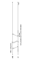
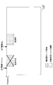
- FIG. 3 is a diagram illustrating an example of a collision type resource region and a non-collision type resource region.
- the collision type resource region and the non-collision type resource region are divided by TDM and FDM.
- TDM and FDM are divided by TDM and FDM.
- FIG. 3 by dividing the collision type resource region and the non-collision type resource region, it is possible to prevent the resources allocated by the scheduling by the radio base station from receiving interference due to the collision type UL transmission.
- the collision type resource region may be set by system information (for example, MIB and / or SIB, broadcast information, etc.) or higher layer signaling (for example, RRC signaling or MAC (Medium Access Control) signaling). .
- the collision type resource region is designated by a layer 1 / layer 2 (L1 / L2) control channel (for example, PDCCH: Physical Downlink Control Channel, EPDCCH: Enhanced Physical Downlink Control Channel, DL control channel, etc.) Also good.
- the collision type resource region may be specified by a combination of system information or higher layer signaling and an L1 / L2 control channel.
- the collision type resource region may be a user terminal specific parameter (for example, user terminal identification information such as C-RNTI or S-TMSI) or a cell specific parameter (for example, a cell identification such as a physical cell ID). Information)) may be derived by the user terminal.
- the packet (UL data) transmitted in the collision-type UL may be divided.
- a packet with a relatively large number of repetitions for coverage extension is transmitted, or when a packet with a relatively large size is transmitted, there is a possibility that a packet to be transmitted by collision-type UL may be divided.
- FIG. 4 is a diagram illustrating an example of occurrence of division of a packet transmitted by collision-type UL.
- FIG. 4 shows a case where a packet having a relatively large number of repetitions is divided as an example, but the case where packet division occurs is not limited to this.
- a plurality of divided packets obtained by dividing one packet here, three divided packets
- transmission of all the divided packets is completed.
- a delay associated with packet division processing and integration processing may occur.
- the present inventors have conceived of preventing division of packets transmitted by collision-type UL by setting a plurality of collision-type resource areas having different parameters (first mode).
- the present inventors pay attention to the point that the non-collision resource area may be insufficient when the collision resource area and the non-collision resource area are separated, and transmit the collision resource area to the non-collision UL transmission. (2nd mode).
- the preamble and / or control information of the UL data may be transmitted together with the UL data, or only the UL data may be transmitted.
- the user terminal may perform collision type UL transmission without establishing UL synchronization with the radio base station, or perform UL type collision after establishing UL synchronization with message 1-4 in FIG. (In the latter case, transmission of the preamble may be omitted).
- the collision type resource region includes a predetermined number of time resources and frequency resources.
- the time resource may be called, for example, a symbol, a subframe interval, a subframe, a transmission time interval (TTI), a scheduling unit, or the like.
- a frequency resource may be called a resource block (PRB), a resource block group (RBG), etc., for example.
- the collision type resource region includes at least code resources (for example, cyclic shift values, OCC (Orthogonal Cover Code), etc.), spatial resources (for example, in the case of spatial multiplexing), and power resources (for example, in the case of power multiplexing). It may be configured to include one.
- the user terminal sets a plurality of collision type resource areas having different parameters, selects at least one collision type resource area from the plurality of collision type resource areas, and uses resources in the selected collision type resource area. Then, UL data may be transmitted.
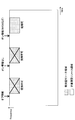
- FIG. 5 is a diagram showing a setting example of a plurality of collision type resource areas according to the first mode.
- Each collision type resource area is set at a predetermined period.
- the collision type resource areas # 1 to # 3 are set with periods # 1 to # 3, respectively.
- the periods # 1 to # 3 are different from each other, but at least two of them may be the same.
- frequency hopping may be applied to each collision type resource region. For example, frequency hopping is applied to each of the collision type resource regions # 1 to # 3 in FIG. Different parameters relating to frequency hopping may be applied to the collision type resource regions # 1 to # 3. Different frequency offset values (# 1, # 1 ', # 2, # 3) are applied to the collision type resource regions # 1 to # 3 in FIG.
- the parameter related to frequency hopping is not limited to the frequency offset value, and may be whether or not frequency hopping is applied.
- the same frequency offset value may be used between the same collision type
- the collision resource areas # 1 to # 3 may each be configured with a different number of frequency resources and / or time resources.
- the collision type resource # 2 includes a larger number of time resources and frequency resources than the collision type resource region # 1 so as to be suitable for transmission of large-capacity UL data.
- the collision type resource # 3 is configured with a larger number of time resources than the collision type resource region # 1 so as to be suitable for transmission of long-time UL data such as when repetition is applied.
- parameters related to the number of repetitions of UL data transmitted in collision-type UL may be different in collision-type resource areas # 1 to # 3.
- repetition non-application may be set in the collision type resource areas # 1 and # 2
- the repetition number of UL data is set to a predetermined number (for example, 100 times). May be.
- parameters related to the transmission processing of UL data transmitted by collision type UL may be different.
- the parameter may include, for example, at least one of a modulation scheme, a coding rate, an MCS index indicating a modulation scheme and a coding rate, a transport block size, and a packet size.
- parameters related to the preamble may be different.
- the parameter relating to the preamble may include at least one of information indicating whether or not to transmit the preamble together with UL data and information indicating a preamble sequence that can be selected by the user terminal.
- the resource group identification information may be a radio network temporary identifier (RNTI) unique to the resource group, for example.
- RNTI radio network temporary identifier
- the parameter may include, for example, at least one of a start point of a collision type resource region (for example, a start index of a frequency resource and / or a time resource), a period, and a frequency offset.
- the numerology may be different.
- the neurology may include at least one of a subcarrier interval, a cyclic prefix (CP) length, a symbol length, and a radio frame configuration.
- CP cyclic prefix
- parameters regarding retransmission control may be different.
- the parameter may include at least one of whether or not the transmission is an initial transmission, a redundant version (RV), a HARQ process number (HPN), and the like.
- parameters related to the multiplexing method may be different.
- the parameter may include at least one of whether to apply code division multiplexing and whether to apply non-orthogonal multiplexing (NOMA) including spatial multiplexing and / or power multiplexing.
- NOMA non-orthogonal multiplexing
- the plurality of collision type resource areas according to the first aspect include the number of time resources, the number of frequency resources, the parameter related to the number of repetitions, the parameter related to transmission processing, the parameter related to frequency hopping, the parameter related to the preamble, and the resource At least one of the group identification information, the parameter related to time and / or frequency position, the neurology, and the parameter related to retransmission control may be different.
- the plurality of collision type resource regions are based on system information (for example, also referred to as MIB and / or SIB, broadcast information, etc.) or higher layer signaling (for example, RRC signaling or MAC signaling). It may be set.
- the plurality of collision type resource regions may be specified by the L1 / L2 control channel.
- the collision type resource region may be specified by a combination of system information or higher layer signaling and an L1 / L2 control channel.
- the plurality of collision-type resource areas include user terminal specific parameters (for example, user terminal identification information such as C-RNTI or S-TMSI) or cell specific parameters (for example, cell such as physical cell ID). May be derived by the user terminal based on the identification information).
- user terminal specific parameters for example, user terminal identification information such as C-RNTI or S-TMSI
- cell specific parameters for example, cell such as physical cell ID. May be derived by the user terminal based on the identification information).
- FIG. 6 is a diagram showing a selection example of a collision type resource region according to the first mode.
- FIG. 6 as in FIG. 5, it is assumed that collision type resource areas # 1 to # 3 having different parameters are set.
- the user terminal selects at least one collision type resource area from among the collision type resource areas # 1 to # 3, and transmits UL data using resources in the selected collision type resource area. .
- the user terminal determines the UL data size, buffer status (BSR: Buffer Status Report), reference signal received power (RSRP), reference signal received quality (RSRQ: Reference Signal Received). Quality), parameters related to the number of repetitions, parameters related to the transmission process, pneumatics, parameters related to retransmission control, and use cases (for example, mMTC, URLLC, etc.), and at least one used for transmitting UL data.
- BSR Buffer Status Report
- RSRP reference signal received power
- RSRQ Reference Signal Received
- Quality Quality
- parameters related to the number of repetitions parameters related to the transmission process
- pneumatics parameters related to retransmission control
- use cases for example, mMTC, URLLC, etc.
- Two collision type resource regions may be selected.
- the user terminal uses a collision type resource region # configured with a larger number of time resources than the collision type resource regions # 1 and 2 as a transmission resource for a packet with a large number of repetitions (for example, 100 times). 3 may be selected.
- the user terminal may select the collision type resource region # 2 as a transmission resource for packets to which repetition is not applied.
- the user terminal may select the collision type resource area # 2 as a transmission resource for a packet having a large packet size. Further, as shown in FIG. 6, the user terminal selects a plurality of collision type resource areas # 2 and # 3, assigns UL data to each of the plurality of collision type resource areas # 2 and # 3, and transmits the selected UL data. May be.
- a higher-order modulation method such as 64QAM (Quadrature Amplitude Modulation), 256QAM is set, and can be used in the collision type resource region # 3.
- a relatively low-order modulation method such as QPSK (Quadrature Phase Shift Keying) or 16QAM is set as a simple modulation method is assumed.
- the user terminal can transmit which modulation method is applied to the UL data assigned to the collision resource areas # 2 and # 3 as UL data control information together with the UL data (see FIG. 2). For example, when mapping UL data modulated by QPSK to collision type resource area # 3 that can use QPSK or 16QAM, the user terminal transmits control information indicating that QPSK is applied together with UL data. Also good.
- the resource area can be appropriately selected according to the application. As a result, it is possible to prevent division of packets transmitted by collision-type UL and to prevent occurrence of delay.
- the non-collision resource area When there is a separation between the non-collision resource area and the collision resource area, the non-collision resource area may be insufficient. Therefore, it is desirable to set the collision type resource area on or off according to the traffic amount of the non-collision type UL transmission so that the collision type resource area can be used for non-collision type UL transmission.
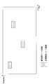
- FIG. 7 is a diagram illustrating an example of a collision type resource region according to the second mode.
- the collision type resource region is TDM and FDMed with the non-collision type resource region.
- the configuration of the resource area shown in FIG. 7 is merely an example, and the present invention is not limited to this.
- the collision type resource region and the non-collision type resource region may be multiplexed by at least one of TDM, FDM, and CDM.
- the non-collision type resource area can be used for transmission of large-capacity data such as eMBB and data with relatively low demand for delay reduction, but the application is not limited to this.
- the radio base station allocates (schedules) resources in the non-collision resource region to the user terminals, and the user terminals transmit or receive UL data using the resources scheduled by the radio base stations.
- DL data can be transmitted or received.
- the collision-type resource area can be used for transmission of data with a small capacity such as MTC and data with relatively low demand for delay reduction, but the application is not limited to this.
- the user terminal transmits UL data using the resource selected from the collision type resource region without the UL grant from the radio base station.
- the user terminal may stop the transmission of UL data using the collision type resource region.
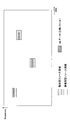
- FIG. 8 is a diagram illustrating an example of on / off control of the collision type resource region according to the second mode.
- the collision type resource region is set by higher layer signaling or system information.
- the user terminal stops transmitting UL data using the collision type resource area. Also good.
- the DL timing may be determined in advance, or may be set by higher layer signaling or system information.
- TDD time division duplex
- FDD frequency division duplex
- the off-information signaling includes lower layer signaling (for example, physical layer signaling, L1 / L2 control channel, DL control channel, etc.), upper layer signaling (for example, RRC signaling, MAC signaling), broadcast (for example, SIB, At least one of system information such as MIB).
- lower layer signaling for example, physical layer signaling, L1 / L2 control channel, DL control channel, etc.
- upper layer signaling for example, RRC signaling, MAC signaling
- broadcast for example, SIB, At least one of system information such as MIB).
- the signaling of off information may be specific to the resource group to which the collision type resource region belongs, may be specific to the cell, or may be specific to the user terminal. If unique to a resource group, identification information of the resource group (for example, RNTI unique to the resource group) may be provided.
- DCI resource group-specific downlink control information
- DL control channel L1 / L2 control channel
- RNTI identification information
- the user terminal when detecting the off information at the DL timing, the user terminal determines that the immediately following collision type resource area cannot be used, and stops the collision type UL transmission using the collision type resource area. On the other hand, if the user terminal does not detect the off information at the DL timing, the user terminal determines that the immediately following collision type resource area can be used, and starts collision type UL transmission using the collision type resource area.
- the collision type resource area can be flexibly used for non-collision type transmission. As a result, frequency use efficiency can be improved.
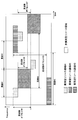
- FIG. 9 is a diagram illustrating another example of the on / off control of the collision type resource region according to the second mode.
- the description has been given of the case where the period during which the collision type resource region is turned off is limited to the collision type resource region immediately after the reception of the off information.
- FIG. 9 illustrates a case where the period during which the collision type resource region is turned off is from when the off state is received to when the on state for turning on the use of the collision type resource region is received. .
- the difference from FIG. 8 will be mainly described.
- the user terminal determines that the collision type resource area cannot be used after detecting the off information at the DL timing until the on information is detected, and the user terminal uses the collision type resource area. Cancel the type UL transmission. Further, when the user terminal detects the ON state, the user terminal determines that the collision type resource area is usable, and starts collision type UL transmission using the collision type resource area.
- DL timing at which ON information is signaled may be determined in advance, or may be set by higher layer signaling or system information.
- On-information signaling includes lower layer signaling (eg, physical layer signaling, L1 / L2 control channel, DL control channel), upper layer signaling (eg, RRC signaling, MAC signaling), broadcast (eg, SIB, MIB). At least one of the system information) can be used.
- the signaling of the on information may be specific to the resource group to which the collision type resource region belongs, may be specific to the cell, or may be specific to the user terminal.
- identification information of the resource group for example, RNTI for the resource group
- the ON information may include control information for collision-type UL transmission in the collision-type resource region to be turned on.
- the control information includes, for example, a modulation scheme, a coding rate, a transport block size, a repetition number, a radio parameter of a collision type resource region (for example, subcarrier interval, CP length, frame configuration, etc., also referred to as a neurology) At least one piece of information included in the UL grant may be indicated.
- region described in the 1st aspect may be included. The user terminal controls transmission of UL data in the collision type resource area based on the control information.
- ON information is included in downlink control information (DCI) specific to resource groups together with an MCS (Modulation and Coding Scheme) index indicating a modulation scheme and a coding rate.
- DCI downlink control information
- MCS Modulation and Coding Scheme
- the user terminal when the user terminal detects the DCI masked with the resource group identification information (RNTI) at the DL timing, based on the ON information included in the DCI, the collision type UL transmission in the collision type resource region. To start. Further, the user terminal may determine the modulation scheme, coding rate, and transport block size applied to the UL data based on the MCS index included in the DCI.
- RNTI resource group identification information
- the collision type resource area can be flexibly used for non-collision type transmission.
- control information for collision-type UL transmission is added to the on-information, transmission of UL data in the collision-type resource area can be controlled more appropriately.
- the collision type resource region can be used for non-collision type transmission, so that traffic (for example, eMBB) of non-collision type transmission increases. Even in this case, the non-collision resource region can be expanded while preventing interference with non-collision transmission.
- traffic for example, eMBB
- wireless communication system Wireless communication system
- the radio communication method according to each of the above aspects is applied.
- wireless communication method which concerns on each said aspect may be applied independently, respectively, and may be applied in combination.
- FIG. 10 is a diagram illustrating an example of a schematic configuration of the wireless communication system according to the present embodiment.
- carrier aggregation (CA) and / or dual connectivity (DC) in which a plurality of basic frequency blocks (component carriers) each having a system bandwidth (for example, 20 MHz) of the LTE system as one unit are applied.
- the wireless communication system 1 may be referred to as SUPER 3G, LTE-A (LTE-Advanced), IMT-Advanced, 4G, 5G, FRA (Future Radio Access), NR (New Rat), or the like.
- the radio communication system 1 shown in FIG. 10 includes a radio base station 11 that forms a macro cell C1, and radio base stations 12a to 12c that are arranged in the macro cell C1 and form a small cell C2 that is narrower than the macro cell C1. .
- the user terminal 20 is arrange
- the user terminal 20 can be connected to both the radio base station 11 and the radio base station 12. It is assumed that the user terminal 20 uses the macro cell C1 and the small cell C2 that use different frequencies simultaneously by CA or DC. In addition, the user terminal 20 can apply CA or DC using a plurality of cells (CC) (for example, two or more CCs). Further, the user terminal can use the license band CC and the unlicensed band CC as a plurality of cells. In addition, it can be set as the structure by which the TDD carrier which applies shortening TTI is contained in either of several cells.
- CC cells
- Communication between the user terminal 20 and the radio base station 11 can be performed using a carrier having a relatively low frequency band (for example, 2 GHz) and a narrow bandwidth (referred to as an existing carrier or a legacy carrier).
- a carrier having a wide bandwidth in a relatively high frequency band for example, 3.5 GHz, 5 GHz, 30 to 70 GHz, etc.
- the same carrier as that between the base station 11 and the base station 11 may be used.
- the configuration of the frequency band used by each radio base station is not limited to this.
- a wired connection for example, an optical fiber compliant with CPRI (Common Public Radio Interface), an X2 interface, etc.
- a wireless connection It can be set as the structure to do.
- the radio base station 11 and each radio base station 12 are connected to the higher station apparatus 30 and connected to the core network 40 via the higher station apparatus 30.
- the upper station device 30 includes, for example, an access gateway device, a radio network controller (RNC), a mobility management entity (MME), and the like, but is not limited thereto.
- RNC radio network controller
- MME mobility management entity
- Each radio base station 12 may be connected to the higher station apparatus 30 via the radio base station 11.
- the radio base station 11 is a radio base station having a relatively wide coverage, and may be called a macro base station, an aggregation node, an eNB (eNodeB), a transmission / reception point, or the like.
- the radio base station 12 is a radio base station having local coverage, and includes a small base station, a micro base station, a pico base station, a femto base station, a HeNB (Home eNodeB), an RRH (Remote Radio Head), and transmission / reception. It may be called a point.
- the radio base stations 11 and 12 are not distinguished, they are collectively referred to as a radio base station 10.
- Each user terminal 20 is a terminal compatible with various communication methods such as LTE and LTE-A, and may include not only a mobile communication terminal but also a fixed communication terminal.
- OFDMA orthogonal frequency division multiple access
- SC-FDMA single carrier-frequency division multiple access
- OFDMA is a multi-carrier transmission scheme that performs communication by dividing a frequency band into a plurality of narrow frequency bands (subcarriers) and mapping data to each subcarrier.
- SC-FDMA is a single-carrier transmission scheme that reduces interference between terminals by dividing the system bandwidth into bands consisting of one or continuous resource blocks for each terminal and using a plurality of terminals with mutually different bands. is there.
- the uplink and downlink radio access schemes are not limited to these combinations, and OFDMA may be used in the UL.
- DL channels DL data channels (PDSCH: Physical Downlink Shared Channel, also referred to as DL shared channel) shared by each user terminal 20, broadcast channels (PBCH: Physical Broadcast Channel), L1 / L2 A control channel or the like is used.
- PDSCH Physical Downlink Shared Channel
- PBCH Physical Broadcast Channel
- SIB System Information Block
- MIB Master Information Block
- L1 / L2 control channels include DL control channels (PDCCH (Physical Downlink Control Channel), EPDCCH (Enhanced Physical Downlink Control Channel)), PCFICH (Physical Control Format Indicator Channel), PHICH (Physical Hybrid-ARQ Indicator Channel), etc. .
- Downlink control information (DCI: Downlink Control Information) including scheduling information of PDSCH and PUSCH is transmitted by PDCCH.
- the number of OFDM symbols used for PDCCH is transmitted by PCFICH.
- the EPDCCH is frequency-division multiplexed with the PDSCH, and is used for transmission of DCI and the like as with the PDCCH.
- HARQ retransmission indication information (ACK / NACK) for PUSCH can be transmitted by at least one of PHICH, PDCCH, and EPDCCH.
- a UL data channel (PUSCH: Physical Uplink Shared Channel, also referred to as a UL shared channel) shared by each user terminal 20, a UL control channel (PUCCH: Physical Uplink Control Channel), random An access channel (PRACH: Physical Random Access Channel) or the like is used.
- PUSCH Physical Uplink Shared Channel
- PUCCH Physical Uplink Control Channel
- PRACH Physical Random Access Channel
- User data and higher layer control information are transmitted by the PUSCH.
- Uplink control information including at least one of retransmission instruction information (ACK / NACK) and channel state information (CSI) is transmitted by PUSCH or PUCCH.
- the PRACH can transmit a random access preamble for establishing a connection with a cell.
- FIG. 11 is a diagram illustrating an example of the overall configuration of the radio base station according to the present embodiment.
- the radio base station 10 includes a plurality of transmission / reception antennas 101, an amplifier unit 102, a transmission / reception unit 103, a baseband signal processing unit 104, a call processing unit 105, and a transmission path interface 106.
- the transmission / reception antenna 101, the amplifier unit 102, and the transmission / reception unit 103 may each be configured to include one or more.
- DL data transmitted from the radio base station 10 to the user terminal 20 is input from the higher station apparatus 30 to the baseband signal processing unit 104 via the transmission path interface 106.
- PDCP Packet Data Convergence Protocol
- RLC Radio Link Control
- MAC Medium Access
- Retransmission control for example, HARQ transmission processing
- scheduling for example, transmission format selection, channel coding, Inverse Fast Fourier Transform (IFFT) processing, precoding processing, and other transmission processing
- IFFT Inverse Fast Fourier Transform
- precoding processing precoding processing
- other transmission processing are performed and the transmission / reception unit 103.
- the DL control signal is also subjected to transmission processing such as channel coding and inverse fast Fourier transform, and is transferred to the transmission / reception unit 103.
- the transmission / reception unit 103 converts the baseband signal output by precoding for each antenna from the baseband signal processing unit 104 to a radio frequency band and transmits the converted signal.
- the radio frequency signal frequency-converted by the transmission / reception unit 103 is amplified by the amplifier unit 102 and transmitted from the transmission / reception antenna 101.
- the transmission / reception unit 103 can be configured by a transmitter / receiver, a transmission / reception circuit, or a transmission / reception device which is described based on common recognition in the technical field according to the present invention.
- the transmission / reception part 103 may be comprised as an integral transmission / reception part, and may be comprised from a transmission part and a receiving part.
- the radio frequency signal received by the transmission / reception antenna 101 is amplified by the amplifier unit 102.
- the transmission / reception unit 103 receives the UL signal amplified by the amplifier unit 102.
- the transmission / reception unit 103 converts the frequency of the received signal into a baseband signal and outputs it to the baseband signal processing unit 104.
- the baseband signal processing unit 104 performs Fast Fourier Transform (FFT) processing, Inverse Discrete Fourier Transform (IDFT) processing, and error correction on user data included in the input UL signal. Decoding, MAC retransmission control reception processing, RLC layer and PDCP layer reception processing are performed and transferred to the upper station apparatus 30 via the transmission path interface 106.
- the call processing unit 105 performs call processing such as communication channel setting and release, state management of the radio base station 10, and radio resource management.
- the transmission path interface 106 transmits and receives signals to and from the higher station apparatus 30 via a predetermined interface.
- the transmission path interface 106 transmits / receives signals (backhaul signaling) to / from other radio base stations 10 via an interface between base stations (for example, an optical fiber compliant with CPRI (Common Public Radio Interface), X2 interface). May be.
- CPRI Common Public Radio Interface
- X2 interface May be.
- the transmission / reception unit 103 includes a DL signal (for example, a DL control signal (DL control channel), a DL data signal (DL data channel, a DL shared channel), a DL reference signal (DM-RS, CSI-RS, etc.), and a discovery signal. , Synchronization signals, broadcast signals, etc.) and UL signals (eg, UL control signals (UL control channel), UL data signals (UL data channel, UL shared channel), UL reference signals, etc.) are received.
- DL signal for example, a DL control signal (DL control channel), a DL data signal (DL data channel, a DL shared channel), a DL reference signal (DM-RS, CSI-RS, etc.
- DM-RS DL reference signal
- CSI-RS CSI-RS
- the transmission / reception unit 103 transmits configuration information (CBUL configuration information) related to collision-type UL transmission using system information or higher layer signaling. Further, the transmission / reception unit 103 receives a UL signal (at least one of a preamble, control information, and UL data) transmitted from the user terminal 20 by collision-type UL transmission.
- configuration information CBUL configuration information
- a UL signal at least one of a preamble, control information, and UL data
- the transmission / reception unit 103 transmits setting information of a plurality of collision type resource areas having different parameters by at least one of system information, higher layer signaling, and DL control channel.
- the setting information includes the number of time resources, the number of frequency resources, a parameter related to the number of repetitions, a parameter related to transmission processing, a parameter related to frequency hopping, a parameter related to preamble, a resource group identification information, a parameter related to time and / or frequency position.
- At least one of the parameters related to the neurology and retransmission control may be included for each collision type resource region.
- the transmission unit and the reception unit of the present invention are configured by the transmission / reception unit 103 and / or the transmission path interface 106.
- FIG. 12 is a diagram illustrating an example of a functional configuration of the radio base station according to the present embodiment. Note that FIG. 12 mainly shows functional blocks of characteristic portions in the present embodiment, and the wireless base station 10 also has other functional blocks necessary for wireless communication. As illustrated in FIG. 12, the baseband signal processing unit 104 includes at least a control unit 301, a transmission signal generation unit 302, a mapping unit 303, a reception signal processing unit 304, and a measurement unit 305.
- the control unit 301 controls the entire radio base station 10.
- the control part 301 can be comprised from the controller, the control circuit, or control apparatus demonstrated based on the common recognition in the technical field which concerns on this invention.
- the control unit 301 controls signal generation by the transmission signal generation unit 302 and signal allocation by the mapping unit 303, for example.
- the control unit 301 also controls signal reception processing by the reception signal processing unit 304 and signal measurement by the measurement unit 305.
- the control unit 301 controls scheduling (for example, resource allocation) of DL signals and / or UL signals. Specifically, the control unit 301 generates and transmits a DCI (DL assignment) including scheduling information of the DL data channel and a DCI (UL grant) including scheduling information of the UL data channel. 302, the mapping unit 303, and the transmission / reception unit 103 are controlled.
- a DCI DL assignment
- a DCI UL grant
- control unit 301 may control collision type UL (CBUL) transmission in which UL data is transmitted from the user terminal 20 without a UL grant.
- CBUL collision type UL
- the control unit 301 may determine the above-described CBUL configuration information such as UL resources that can be used for collision-type UL transmission.
- control unit 301 may control reception of UL data in accordance with a transmission format for collision-type UL transmission.
- the transmission format may include an access channel that transmits a randomly selected preamble, a control channel that transmits UL data control information, and a data channel that transmits UL data. .
- control unit 301 may detect UL transmission using the preamble. Further, the control unit 301 may blind-decode the UL control channel and identify the user terminal 20 based on the detected control information. Further, the control unit 301 may control the reception processing (demodulation, decoding, etc.) of UL data from the user terminal 20 based on the control information. Further, the control unit 301 may control beam search and / or channel estimation performed based on the preamble.
- control unit 301 may control the setting of a plurality of collision type resource areas having different parameters (first mode). Specifically, the control unit 301 includes a number of time resources, a number of frequency resources, a parameter related to the number of repetitions, a parameter related to transmission processing, a parameter related to frequency hopping, a parameter related to preamble, resource group identification information, time and / or frequency. At least one of the parameter relating to the position, the neurology, and the parameter relating to the retransmission control may be determined for each collision type resource region. In addition, the control unit 301 may control generation and transmission processing of setting information indicating the determination result.
- control unit 301 may control the on / off state of the collision type resource region (second mode). Specifically, the control unit 301 turns off the use of the collision resource region and / or the turn on of the collision resource region based on the traffic amount of the non-collision resource region.
- Information signaling may be controlled. The signaling may be specific to a resource group including a collision type resource region, specific to a cell, or specific to a user terminal 20.
- the transmission signal generation unit 302 generates a DL signal (DL reference signal such as DL control channel, DL data channel, DM-RS, etc.) based on an instruction from the control unit 301, and outputs the DL signal to the mapping unit 303.
- the transmission signal generation unit 302 can be configured by a signal generator, a signal generation circuit, or a signal generation device described based on common recognition in the technical field according to the present invention.
- the mapping unit 303 maps the DL signal generated by the transmission signal generation unit 302 to a predetermined radio resource based on an instruction from the control unit 301, and outputs the DL signal to the transmission / reception unit 103.
- the mapping unit 303 can be configured by a mapper, a mapping circuit, or a mapping device described based on common recognition in the technical field according to the present invention.
- the reception signal processing unit 304 performs reception processing (for example, demapping, demodulation, decoding, etc.) on the reception signal input from the transmission / reception unit 103.
- the received signal is, for example, a UL signal (UL control channel, UL data channel, UL reference signal, etc.) transmitted from the user terminal 20.
- the reception signal processing unit 304 can be configured by a signal processor, a signal processing circuit, or a signal processing device described based on common recognition in the technical field according to the present invention.
- the reception signal processing unit 304 outputs the information decoded by the reception processing to the control unit 301.
- the reception processing unit 304 outputs at least one of a preamble, control information, and UL data to the control unit 301.
- the reception signal processing unit 304 outputs the reception signal and the signal after reception processing to the measurement unit 305.
- the measurement unit 305 performs measurement on the received signal.
- the measurement part 305 can be comprised from the measuring device, measurement circuit, or measurement apparatus demonstrated based on common recognition in the technical field which concerns on this invention.
- the measurement unit 305 may measure, for example, received power (for example, RSRP (Reference Signal Received Power)), reception quality (for example, RSRQ (Reference Signal Received Quality)), channel state, and the like of the received signal.
- the measurement result may be output to the control unit 301.
- FIG. 13 is a diagram illustrating an example of the overall configuration of the user terminal according to the present embodiment.
- the user terminal 20 includes a plurality of transmission / reception antennas 201, an amplifier unit 202, a transmission / reception unit 203, a baseband signal processing unit 204, and an application unit 205.
- the transmission / reception antenna 201, the amplifier unit 202, and the transmission / reception unit 203 may each be configured to include one or more.
- the radio frequency signal received by the transmission / reception antenna 201 is amplified by the amplifier unit 202.
- the transmission / reception unit 203 receives the DL signal amplified by the amplifier unit 202.
- the transmission / reception unit 203 converts the frequency of the received signal into a baseband signal and outputs it to the baseband signal processing unit 204.
- the transmission / reception unit 203 can be configured by a transmitter / receiver, a transmission / reception circuit, or a transmission / reception device described based on common recognition in the technical field according to the present invention.
- the transmission / reception unit 203 may be configured as an integral transmission / reception unit, or may be configured from a transmission unit and a reception unit.
- the baseband signal processing unit 204 performs FFT processing, error correction decoding, retransmission control reception processing, and the like on the input baseband signal.
- the DL data is transferred to the application unit 205.
- the application unit 205 performs processing related to layers higher than the physical layer and the MAC layer. Of the DL data, system information and higher layer control information are also transferred to the application unit 205.
- UL data is input from the application unit 205 to the baseband signal processing unit 204.
- the baseband signal processing unit 204 performs transmission / reception by performing retransmission control transmission processing (for example, HARQ transmission processing), channel coding, precoding, discrete Fourier transform (DFT) processing, IFFT processing, and the like. Is transferred to the unit 203.
- the transmission / reception unit 203 converts the baseband signal output from the baseband signal processing unit 204 into a radio frequency band and transmits it.
- the radio frequency signal frequency-converted by the transmission / reception unit 203 is amplified by the amplifier unit 202 and transmitted from the transmission / reception antenna 201.
- the transmission / reception unit 203 includes a DL signal (for example, a DL control signal (DL control channel), a DL data signal (DL data channel, a DL shared channel), a DL reference signal (DM-RS, CSI-RS, etc.), and a discovery signal.
- a DL signal for example, a DL control signal (DL control channel), a DL data signal (DL data channel, a DL shared channel), a DL reference signal (DM-RS, CSI-RS, etc.), and a discovery signal.
- a UL signal for example, UL control signal (UL control channel), UL data signal (UL data channel, UL shared channel), UL reference signal, etc.
- the transmission / reception unit 203 receives configuration information (CBUL configuration information) related to collision-type UL transmission through system information or higher layer signaling.
- the transmission / reception unit 203 transmits a UL signal (at least one of a preamble, control information, and UL data) based on the transmission format of the collision-type UL transmission.
- the transmission / reception unit 203 receives setting information of a plurality of collision type resource areas having different parameters by at least one of system information, higher layer signaling, and DL control channel.
- the setting information includes the number of time resources, the number of frequency resources, a parameter related to the number of repetitions, a parameter related to transmission processing, a parameter related to frequency hopping, a parameter related to preamble, a resource group identification information, a parameter related to time and / or frequency position.
- At least one of the parameters related to the neurology and retransmission control may be included for each collision type resource region.
- FIG. 14 is a diagram illustrating an example of a functional configuration of the user terminal according to the present embodiment. Note that FIG. 14 mainly shows functional blocks of characteristic portions in the present embodiment, and the user terminal 20 also has other functional blocks necessary for wireless communication. As illustrated in FIG. 14, the baseband signal processing unit 204 included in the user terminal 20 includes a control unit 401, a transmission signal generation unit 402, a mapping unit 403, a reception signal processing unit 404, and a measurement unit 405. At least.
- the control unit 401 controls the entire user terminal 20.
- the control unit 401 can be composed of a controller, a control circuit, or a control device described based on common recognition in the technical field according to the present invention.
- the control unit 401 controls, for example, signal generation by the transmission signal generation unit 402 and signal allocation by the mapping unit 403.
- the control unit 401 controls signal reception processing by the reception signal processing unit 404 and signal measurement by the measurement unit 405.
- the control unit 401 acquires the DL control channel and the DL data channel transmitted from the radio base station 10 from the received signal processing unit 404. Specifically, the control unit 401 blindly decodes the DL control channel to detect DCI, and controls the transmission / reception unit 203 and the received signal processing unit 404 to receive the DL data channel based on the DCI. Further, the control unit 401 estimates the channel gain based on the DL reference signal, and demodulates the DL data channel based on the estimated channel gain.
- the control unit 401 controls transmission of retransmission control information (for example, HARQ-ACK) transmitted on the UL control channel or the UL data channel based on the result of determining whether or not retransmission control is required for the DL data channel. May be. Moreover, the control part 401 may control transmission of the channel state information (CSI: Channel State Information) generated based on the DL reference signal.
- CSI Channel State Information
- control unit 401 controls collision type UL (CBUL) transmission. Specifically, the control unit 401 may control transmission of UL data without a UL grant according to a transmission format for collision-type UL transmission.
- CBUL collision type UL
- control unit 401 may determine a UL resource used for collision-type UL transmission based on the CBUL configuration information.
- the UL resource may be at least one of a time resource, a frequency resource, a resource group, a code resource, a power resource, and a spatial resource.
- control unit 401 may randomly select a preamble from a plurality of preambles indicated by the CBUL configuration information.
- control unit 401 may control the setting of a plurality of collision type resource areas having different parameters as described above (first mode). Specifically, the control unit 401 uses the system information (for example, also referred to as MIB and / or SIB, broadcast information, etc.) or higher layer signaling (for example, RRC signaling or MAC signaling) to generate the plurality of collision-type resources. An area may be set.
- system information for example, also referred to as MIB and / or SIB, broadcast information, etc.
- higher layer signaling for example, RRC signaling or MAC signaling
- control unit 401 may determine the plurality of collision type resource regions based on DCI transmitted through the L1 / L2 control channel. Alternatively, the control unit 401 may determine the plurality of collision type resource regions based on a combination of system information or higher layer signaling and DCI transmitted through the L1 / L2 control channel.
- control unit 401 uses parameters specific to the user terminal (for example, user terminal identification information such as C-RNTI or S-TMSI) or cell specific parameters (for example, cell identification information such as a physical cell ID).
- user terminal identification information such as C-RNTI or S-TMSI
- cell specific parameters for example, cell identification information such as a physical cell ID.
- the plurality of collision-type resource regions may be determined based on
- control unit 401 may select at least one collision type resource area from among the collision type resource areas (first mode). Specifically, the user terminal performs the UL data size, buffer status, reference signal reception power (RSRP), reference signal reception quality (RSRQ), parameters related to the number of repetitions, parameters related to the transmission process, On the basis of at least one of parameters related to logic and retransmission control, at least one collision type resource region used for UL data transmission may be selected.
- RSRP reference signal reception power
- RSRQ reference signal reception quality
- control unit 401 may control the on / off state of the collision type resource region (second mode). Specifically, when the off information for turning off the use of the collision type resource region is signaled, the control unit 401 may stop the transmission of UL data using the collision type resource region. For example, when the off information included in DCI is blind-decoded by the DL control channel, the control unit 401 may stop transmitting UL data using the collision type resource region based on the off information.
- the control unit 401 may stop transmitting UL data using the immediately following collision type resource area. .
- the control unit 401 may start transmission of UL data using the immediately following collision resource region (FIG. 8).
- control unit 401 may stop transmission of UL data using the collision type resource region until the on information for turning on the use of the collision type resource region is signaled after the off information is signaled. Good ( Figure 9). Further, the control unit 401 may start transmission of UL data using the collision type resource region after the ON information is signaled.
- the transmission signal generation unit 402 generates a UL signal (UL control channel, UL data channel, UL reference signal, etc.) based on an instruction from the control unit 401, and outputs the UL signal to the mapping unit 403.
- the transmission signal generation unit 402 can be configured by a signal generator, a signal generation circuit, or a signal generation device described based on common recognition in the technical field according to the present invention.
- the transmission signal generation unit 402 generates a UL data channel based on an instruction from the control unit 401. For example, when the UL grant is included in the DL control channel notified from the radio base station 10, the transmission signal generation unit 402 is instructed by the control unit 401 to generate a UL data channel.
- the mapping unit 403 maps the UL signal generated by the transmission signal generation unit 402 to a radio resource based on an instruction from the control unit 401, and outputs it to the transmission / reception unit 203.
- the mapping unit 403 can be configured by a mapper, a mapping circuit, or a mapping device described based on common recognition in the technical field according to the present invention.
- the reception signal processing unit 404 performs reception processing (for example, demapping, demodulation, decoding, etc.) on the reception signal input from the transmission / reception unit 203.
- the received signal is, for example, a DL signal (DL control channel, DL data channel, DL reference signal, etc.) transmitted from the radio base station 10.
- the reception signal processing unit 404 can be configured by a signal processor, a signal processing circuit, or a signal processing device described based on common recognition in the technical field according to the present invention. Further, the reception signal processing unit 404 can constitute a reception unit according to the present invention.
- the received signal processing unit 404 performs blind decoding on the DL control channel that schedules transmission and / or reception of the DL data channel based on an instruction from the control unit 401, and performs DL data channel reception processing based on the DCI.
- Received signal processing section 404 estimates the channel gain based on DM-RS or CRS, and demodulates the DL data channel based on the estimated channel gain.
- the reception signal processing unit 404 outputs the information decoded by the reception processing to the control unit 401.
- the reception signal processing unit 404 outputs broadcast information, system information, RRC signaling, DCI, and the like to the control unit 401, for example.
- the reception signal processing unit 404 may output the data decoding result to the control unit 401.
- the reception signal processing unit 404 outputs the reception signal and the signal after reception processing to the measurement unit 405.
- the measurement unit 405 performs measurement on the received signal.
- the measurement part 405 can be comprised from the measuring device, measurement circuit, or measurement apparatus demonstrated based on common recognition in the technical field which concerns on this invention.
- the measurement unit 405 may measure, for example, the received power (for example, RSRP), DL reception quality (for example, RSRQ), channel state, and the like of the received signal.
- the measurement result may be output to the control unit 401.
- each functional block may be realized by one device physically and / or logically coupled, and two or more devices physically and / or logically separated may be directly and / or indirectly. (For example, wired and / or wireless) and may be realized by these plural devices.
- the radio base station, user terminal, and the like in this embodiment may function as a computer that performs processing of the radio communication method of the present invention.
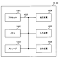
- FIG. 15 is a diagram illustrating an example of a hardware configuration of the radio base station and the user terminal according to the present embodiment.
- the wireless base station 10 and the user terminal 20 described above may be physically configured as a computer device including a processor 1001, a memory 1002, a storage 1003, a communication device 1004, an input device 1005, an output device 1006, a bus 1007, and the like. Good.
- the term “apparatus” can be read as a circuit, a device, a unit, or the like.
- the hardware configurations of the radio base station 10 and the user terminal 20 may be configured to include one or a plurality of each device illustrated in the figure, or may be configured not to include some devices.
- processor 1001 may be implemented by one or more chips.
- each function in the radio base station 10 and the user terminal 20 reads predetermined software (program) on hardware such as the processor 1001 and the memory 1002, so that the processor 1001 performs computation and communication by the communication device 1004.
- predetermined software program
- it is realized by controlling data reading and / or writing in the memory 1002 and the storage 1003.
- the processor 1001 controls the entire computer by operating an operating system, for example.
- the processor 1001 may be configured by a central processing unit (CPU) including an interface with peripheral devices, a control device, an arithmetic device, a register, and the like.
- CPU central processing unit
- the baseband signal processing unit 104 (204) and the call processing unit 105 described above may be realized by the processor 1001.
- the processor 1001 reads programs (program codes), software modules, data, and the like from the storage 1003 and / or the communication device 1004 to the memory 1002, and executes various processes according to these.
- programs program codes
- software modules software modules
- data data
- the like data
- the control unit 401 of the user terminal 20 may be realized by a control program stored in the memory 1002 and operated by the processor 1001, and may be realized similarly for other functional blocks.
- the memory 1002 is a computer-readable recording medium such as a ROM (Read Only Memory), an EPROM (Erasable Programmable ROM), an EEPROM (Electrically EPROM), a RAM (Random Access Memory), or any other suitable storage medium. It may be configured by one.
- the memory 1002 may be called a register, a cache, a main memory (main storage device), or the like.
- the memory 1002 can store programs (program codes), software modules, and the like that can be executed to implement the wireless communication method according to an embodiment of the present invention.
- the storage 1003 is a computer-readable recording medium such as a flexible disk, a floppy (registered trademark) disk, a magneto-optical disk (for example, a compact disk (CD-ROM (Compact Disc ROM)), a digital versatile disk, Blu-ray® disk), removable disk, hard disk drive, smart card, flash memory device (eg, card, stick, key drive), magnetic stripe, database, server, or other suitable storage medium It may be constituted by.
- the storage 1003 may be referred to as an auxiliary storage device.
- the communication device 1004 is hardware (transmission / reception device) for performing communication between computers via a wired and / or wireless network, and is also referred to as a network device, a network controller, a network card, a communication module, or the like.
- the communication device 1004 includes, for example, a high-frequency switch, a duplexer, a filter, a frequency synthesizer, etc., in order to realize frequency division duplex (FDD) and / or time division duplex (TDD). It may be configured.
- FDD frequency division duplex
- TDD time division duplex
- the transmission / reception antenna 101 (201), the amplifier unit 102 (202), the transmission / reception unit 103 (203), the transmission path interface 106, and the like described above may be realized by the communication device 1004.
- the input device 1005 is an input device (for example, a keyboard, a mouse, a microphone, a switch, a button, a sensor, etc.) that accepts an input from the outside.
- the output device 1006 is an output device (for example, a display, a speaker, an LED (Light Emitting Diode) lamp, etc.) that performs output to the outside.
- the input device 1005 and the output device 1006 may have an integrated configuration (for example, a touch panel).
- each device such as the processor 1001 and the memory 1002 is connected by a bus 1007 for communicating information.
- the bus 1007 may be configured with a single bus or may be configured with different buses between apparatuses.
- the radio base station 10 and the user terminal 20 include a microprocessor, a digital signal processor (DSP), an ASIC (Application Specific Integrated Circuit), a PLD (Programmable Logic Device), an FPGA (Field Programmable Gate Array), and the like. It may be configured including hardware, and a part or all of each functional block may be realized by the hardware. For example, the processor 1001 may be implemented by at least one of these hardware.
- DSP digital signal processor
- ASIC Application Specific Integrated Circuit
- PLD Programmable Logic Device
- FPGA Field Programmable Gate Array
- the channel and / or symbol may be a signal (signaling).
- the signal may be a message.
- the reference signal may be abbreviated as RS (Reference Signal), and may be referred to as a pilot, a pilot signal, or the like depending on an applied standard.
- a component carrier CC: Component Carrier
- CC Component Carrier
- the radio frame may be configured with one or a plurality of periods (frames) in the time domain.
- Each of the one or more periods (frames) constituting the radio frame may be referred to as a subframe.
- a subframe may be composed of one or more slots in the time domain.
- the slot may be configured with one or a plurality of symbols (OFDM (Orthogonal Frequency Division Multiplexing) symbol, SC-FDMA (Single Carrier Frequency Division Multiple Access) symbol, etc.) in the time domain).
- OFDM Orthogonal Frequency Division Multiplexing
- SC-FDMA Single Carrier Frequency Division Multiple Access
- the radio frame, subframe, slot, and symbol all represent a time unit when transmitting a signal.
- Different names may be used for the radio frame, the subframe, the slot, and the symbol.
- one subframe may be referred to as a transmission time interval (TTI)
- a plurality of consecutive subframes may be referred to as a TTI
- one slot may be referred to as a TTI.
- the subframe or TTI may be a subframe (1 ms) in the existing LTE, a period shorter than 1 ms (for example, 1-13 symbols), or a period longer than 1 ms. Also good.
- TTI means, for example, a minimum time unit for scheduling in wireless communication.
- a radio base station performs scheduling to allocate radio resources (frequency bandwidth, transmission power, etc. that can be used in each user terminal) to each user terminal in units of TTI.
- the definition of TTI is not limited to this.
- the TTI may be a transmission time unit of a channel-encoded data packet (transport block), or may be a processing unit such as scheduling or link adaptation.
- a TTI having a time length of 1 ms may be called a normal TTI (TTI in LTE Rel. 8-12), a normal TTI, a long TTI, a normal subframe, a normal subframe, or a long subframe.
- TTI shorter than a normal TTI may be called a shortened TTI, a short TTI, a shortened subframe, a short subframe, or the like.
- a resource block is a resource allocation unit in the time domain and the frequency domain, and may include one or a plurality of continuous subcarriers (subcarriers) in the frequency domain. Further, the RB may include one or a plurality of symbols in the time domain, and may have a length of one slot, one subframe, or 1 TTI. One TTI and one subframe may each be composed of one or a plurality of resource blocks.
- the RB may be called a physical resource block (PRB: Physical RB), a PRB pair, an RB pair, or the like.
- the resource block may be composed of one or a plurality of resource elements (RE: Resource Element).
- RE Resource Element
- 1RE may be a radio resource region of 1 subcarrier and 1 symbol.
- the structure of the above-described radio frame, subframe, slot, symbol, and the like is merely an example.
- the configuration such as the cyclic prefix (CP) length can be changed in various ways.
- information, parameters, and the like described in this specification may be represented by absolute values, may be represented by relative values from a predetermined value, or may be represented by other corresponding information.
- the radio resource may be indicated by a predetermined index.
- mathematical formulas and the like using these parameters may differ from those explicitly disclosed herein.
- PUCCH Physical Uplink Control Channel
- PDCCH Physical Downlink Control Channel
- information elements can be identified by any suitable name, so the various channels and information elements assigned to them.
- the name is not limiting in any way.
- information, signals, etc. can be output from the upper layer to the lower layer and / or from the lower layer to the upper layer.
- Information, signals, and the like may be input / output via a plurality of network nodes.
- the input / output information, signals, etc. may be stored in a specific location (for example, a memory), or may be managed by a management table. Input / output information, signals, and the like can be overwritten, updated, or added. The output information, signals, etc. may be deleted. Input information, signals, and the like may be transmitted to other devices.
- information notification includes physical layer signaling (eg, downlink control information (DCI), uplink control information (UCI)), upper layer signaling (eg, RRC (Radio Resource Control) signaling), It may be implemented by broadcast information (Master Information Block (MIB), System Information Block (SIB), etc.), MAC (Medium Access Control) signaling), other signals, or a combination thereof.
- DCI downlink control information
- UCI uplink control information
- RRC Radio Resource Control
- MIB Master Information Block
- SIB System Information Block
- MAC Medium Access Control
- the physical layer signaling may be referred to as L1 / L2 (Layer 1 / Layer 2) control information (L1 / L2 control signal), L1 control information (L1 control signal), or the like.
- the RRC signaling may be referred to as an RRC message, and may be, for example, an RRC connection setup (RRCConnectionSetup) message, an RRC connection reconfiguration (RRCConnectionReconfiguration) message, or the like.
- the MAC signaling may be notified by, for example, a MAC control element (MAC CE (Control Element)).
- notification of predetermined information is not limited to explicitly performed, but implicitly (for example, by not performing notification of the predetermined information or another (By notification of information).
- the determination may be performed by a value represented by 1 bit (0 or 1), or may be performed by a boolean value represented by true or false.
- the comparison may be performed by numerical comparison (for example, comparison with a predetermined value).
- software, instructions, information, etc. may be transmitted / received via a transmission medium.
- software can use websites, servers using wired technology (coaxial cable, fiber optic cable, twisted pair, digital subscriber line (DSL), etc.) and / or wireless technology (infrared, microwave, etc.) , Or other remote sources, these wired and / or wireless technologies are included within the definition of transmission media.
- system and “network” used in this specification are used interchangeably.
- base station BS
- radio base station eNB
- cell e.g., a fixed station
- eNodeB eNodeB
- cell group e.g., a cell
- carrier femtocell
- component carrier e.g., a fixed station, NodeB, eNodeB (eNB), access point, transmission point, reception point, femtocell, and small cell.
- the base station can accommodate one or a plurality of (for example, three) cells (also called sectors). If the base station accommodates multiple cells, the entire coverage area of the base station can be partitioned into multiple smaller areas, each smaller area being a base station subsystem (eg, an indoor small base station (RRH: The term “cell” or “sector” refers to part or all of the coverage area of a base station and / or base station subsystem that provides communication service in this coverage. Point to.
- RRH indoor small base station
- MS mobile station
- UE user equipment
- terminal may be used interchangeably.
- a base station may also be called in terms such as a fixed station, NodeB, eNodeB (eNB), access point, transmission point, reception point, femtocell, and small cell.
- NodeB NodeB
- eNodeB eNodeB
- access point transmission point
- reception point femtocell
- small cell small cell
- a mobile station is defined by those skilled in the art as a subscriber station, mobile unit, subscriber unit, wireless unit, remote unit, mobile device, wireless device, wireless communication device, remote device, mobile subscriber station, access terminal, mobile terminal, wireless It may also be called terminal, remote terminal, handset, user agent, mobile client, client or some other suitable terminology.
- the radio base station in this specification may be read by the user terminal.
- each aspect / embodiment of the present invention may be applied to a configuration in which communication between a radio base station and a user terminal is replaced with communication between a plurality of user terminals (D2D: Device-to-Device).
- the user terminal 20 may have a function that the wireless base station 10 has.
- words such as “up” and “down” may be read as “side”.
- the uplink channel may be read as a side channel.
- a user terminal in this specification may be read by a radio base station.
- the wireless base station 10 may have a function that the user terminal 20 has.
- the specific operation assumed to be performed by the base station may be performed by the upper node in some cases.
- various operations performed for communication with a terminal may be performed by one or more network nodes other than the base station and the base station (for example, It is obvious that this can be done by MME (Mobility Management Entity), S-GW (Serving-Gateway), etc., but not limited thereto) or a combination thereof.
- MME Mobility Management Entity
- S-GW Serving-Gateway
- each aspect / embodiment described in this specification may be used alone, in combination, or may be switched according to execution.
- the order of the processing procedures, sequences, flowcharts, and the like of each aspect / embodiment described in this specification may be changed as long as there is no contradiction.
- the methods described herein present the elements of the various steps in an exemplary order and are not limited to the specific order presented.
- Each aspect / embodiment described herein includes LTE (Long Term Evolution), LTE-A (LTE-Advanced), LTE-B (LTE-Beyond), SUPER 3G, IMT-Advanced, 4G (4th generation mobile). communication system), 5G (5th generation mobile communication system), FRA (Future Radio Access), New-RAT (Radio Access Technology), NR (New Radio), NX (New radio access), FX (Future generation radio access), GSM (registered trademark) (Global System for Mobile communications), CDMA2000, UMB (Ultra Mobile Broadband), IEEE 802.11 (Wi-Fi (registered trademark)), IEEE 802.16 (WiMAX (registered trademark)), IEEE 802 .20, UWB (Ultra-WideBand), Bluetooth (registered trademark), The present invention may be applied to a system using other appropriate wireless communication methods and / or a next generation system extended based on these.
- the phrase “based on” does not mean “based only on”, unless expressly specified otherwise. In other words, the phrase “based on” means both “based only on” and “based at least on.”
- any reference to elements using designations such as “first”, “second”, etc. as used herein does not generally limit the amount or order of those elements. These designations can be used herein as a convenient way to distinguish between two or more elements. Thus, reference to the first and second elements does not mean that only two elements can be employed or that the first element must precede the second element in some way.
- determining may encompass a wide variety of actions. For example, “determination” means calculating, computing, processing, deriving, investigating, looking up (eg, table, database or other data). It may be considered to “judge” (search in structure), ascertaining, etc.
- “determination (decision)” includes receiving (for example, receiving information), transmitting (for example, transmitting information), input (input), output (output), access ( accessing) (e.g., accessing data in memory), etc. may be considered to be “determining”. Also, “determination” is considered to be “determination (resolving)”, “selecting”, “choosing”, “establishing”, “comparing”, etc. Also good. That is, “determination (determination)” may be regarded as “determination (determination)” of some operation.
- the terms “connected”, “coupled”, or any variation thereof refers to any direct or indirect connection between two or more elements or By coupling, it can include the presence of one or more intermediate elements between two elements that are “connected” or “coupled” to each other.
- the coupling or connection between the elements may be physical, logical, or a combination thereof.
- the two elements are radio frequency by using one or more wires, cables and / or printed electrical connections, and as some non-limiting and non-inclusive examples
- electromagnetic energy such as electromagnetic energy having a wavelength in the region, microwave region, and light (both visible and invisible) region, it can be considered to be “connected” or “coupled” to each other.
Landscapes
- Engineering & Computer Science (AREA)
- Computer Networks & Wireless Communication (AREA)
- Signal Processing (AREA)
- Mobile Radio Communication Systems (AREA)
Abstract
Priority Applications (5)
| Application Number | Priority Date | Filing Date | Title |
|---|---|---|---|
| MX2018013646A MX2018013646A (es) | 2016-05-12 | 2017-05-11 | Terminal de usuario y metodo de comunicacion por radio. |
| US16/300,363 US20190166619A1 (en) | 2016-05-12 | 2017-05-11 | User terminal and radio communication method |
| EP17796206.5A EP3457804A4 (fr) | 2016-05-12 | 2017-05-11 | Terminal utilisateur, et procédé de communication sans fil |
| CN201780028830.7A CN109076612B (zh) | 2016-05-12 | 2017-05-11 | 终端、基站、系统、以及无线通信方法 |
| JP2018517066A JP7111612B2 (ja) | 2016-05-12 | 2017-05-11 | 端末、無線通信方法、基地局及びシステム |
Applications Claiming Priority (2)
| Application Number | Priority Date | Filing Date | Title |
|---|---|---|---|
| JP2016096437 | 2016-05-12 | ||
| JP2016-096437 | 2016-05-12 |
Publications (1)
| Publication Number | Publication Date |
|---|---|
| WO2017195848A1 true WO2017195848A1 (fr) | 2017-11-16 |
Family
ID=60267255
Family Applications (1)
| Application Number | Title | Priority Date | Filing Date |
|---|---|---|---|
| PCT/JP2017/017771 WO2017195848A1 (fr) | 2016-05-12 | 2017-05-11 | Terminal utilisateur, et procédé de communication sans fil |
Country Status (6)
| Country | Link |
|---|---|
| US (1) | US20190166619A1 (fr) |
| EP (1) | EP3457804A4 (fr) |
| JP (1) | JP7111612B2 (fr) |
| CN (1) | CN109076612B (fr) |
| MX (1) | MX2018013646A (fr) |
| WO (1) | WO2017195848A1 (fr) |
Cited By (1)
| Publication number | Priority date | Publication date | Assignee | Title |
|---|---|---|---|---|
| US11800557B2 (en) | 2018-06-21 | 2023-10-24 | Nokia Technologies Oy | Transport block size for contention free random access in random access procedure |
Families Citing this family (10)
| Publication number | Priority date | Publication date | Assignee | Title |
|---|---|---|---|---|
| CN113329498A (zh) * | 2015-11-13 | 2021-08-31 | Oppo广东移动通信有限公司 | 无线资源分配的方法和装置 |
| CN108024359B (zh) * | 2016-11-04 | 2022-01-14 | 华为技术有限公司 | 上行接入方法、基站和用户设备 |
| CN108631976B (zh) * | 2017-03-23 | 2021-07-16 | 华为技术有限公司 | 一种通信方法及装置 |
| US10667282B2 (en) * | 2017-07-11 | 2020-05-26 | Qualcomm Incorporated | Uplink hopping pattern modes for hybrid automatic repeat request (HARQ) transmissions |
| CN114142979A (zh) * | 2017-08-11 | 2022-03-04 | 华为技术有限公司 | 一种获取参考信号的方法、装置和计算机可读存储介质 |
| US11196512B2 (en) * | 2018-06-29 | 2021-12-07 | Qualcomm Incorporated | Resolving decodability for subsequent transmissions whose throughput exceeds a threshold |
| US10833818B2 (en) * | 2018-11-13 | 2020-11-10 | Qualcomm Incorporated | Resource exclusion in a half duplex based wireless communication system |
| CN111726884B (zh) * | 2019-03-20 | 2022-06-07 | 中国移动通信有限公司研究院 | 一种指示方法及设备 |
| EP4042797A1 (fr) * | 2019-10-11 | 2022-08-17 | Nokia Technologies Oy | Transmission de données en une étape dans un système de télécommunication |
| CN114599114A (zh) * | 2020-12-07 | 2022-06-07 | 上海朗帛通信技术有限公司 | 一种被用于中继无线通信中的方法和装置 |
Citations (2)
| Publication number | Priority date | Publication date | Assignee | Title |
|---|---|---|---|---|
| US20120044878A1 (en) * | 2010-08-19 | 2012-02-23 | Motorola, Inc. | Method and apparatus for providing contention-based resource zones in a wireless network |
| WO2016053639A1 (fr) * | 2014-10-02 | 2016-04-07 | Qualcomm Incorporated | Transmissions de liaison montante basées sur des conflits d'accès pour la réduction des délais de transit |
Family Cites Families (13)
| Publication number | Priority date | Publication date | Assignee | Title |
|---|---|---|---|---|
| KR101789326B1 (ko) * | 2009-10-21 | 2017-10-24 | 엘지전자 주식회사 | 중계국을 포함하는 무선 통신 시스템에서 참조 신호 전송 방법 및 장치 |
| WO2011068385A2 (fr) * | 2009-12-03 | 2011-06-09 | 엘지전자 주식회사 | Procédé et appareil permettant une transmission en mode contention efficace dans un système de communication sans fil |
| MY162196A (en) * | 2010-01-08 | 2017-05-31 | Interdigital Patent Holdings Inc | Channel state information transmission for multiple carriers |
| KR101813031B1 (ko) * | 2010-04-13 | 2017-12-28 | 엘지전자 주식회사 | 상향링크 신호를 전송하는 방법 및 이를 위한 장치 |
| EP2761796A4 (fr) * | 2011-09-30 | 2015-07-15 | Intel Corp | Service de diffusion groupée utilisant une sous-trame de diffusion individuelle |
| WO2013077625A1 (fr) * | 2011-11-23 | 2013-05-30 | 엘지전자 주식회사 | Procédé et dispositif pour envoyer/obtenir des informations de commande dans un système de communication sans fil |
| CN104205968B (zh) * | 2012-03-21 | 2018-06-29 | 富士通株式会社 | 无线通信系统 |
| CN102882644B (zh) * | 2012-09-21 | 2015-09-16 | 中兴通讯股份有限公司 | 下行控制信息的检测处理、检测方法及装置 |
| CN104854811B (zh) * | 2012-09-26 | 2018-04-24 | 交互数字专利控股公司 | 动态tdd上行链路/下行链路配置方法 |
| US9918323B2 (en) * | 2013-04-02 | 2018-03-13 | Lg Electronics Inc. | Method and apparatus for transmitting and receiving signal in wireless communication system |
| JP6224358B2 (ja) * | 2013-06-14 | 2017-11-01 | 株式会社Nttドコモ | 無線基地局、ユーザ端末及び無線通信方法 |
| WO2015018005A1 (fr) * | 2013-08-07 | 2015-02-12 | Panasonic Intellectual Property Corporation Of America | Appareil de station de base, terminal, procédé d'émission et procédé de réception |
| CN114710242A (zh) * | 2016-04-01 | 2022-07-05 | 华为技术有限公司 | 用于srs切换、发送和增强的系统与方法 |
-
2017
- 2017-05-11 US US16/300,363 patent/US20190166619A1/en not_active Abandoned
- 2017-05-11 MX MX2018013646A patent/MX2018013646A/es unknown
- 2017-05-11 EP EP17796206.5A patent/EP3457804A4/fr not_active Withdrawn
- 2017-05-11 CN CN201780028830.7A patent/CN109076612B/zh active Active
- 2017-05-11 WO PCT/JP2017/017771 patent/WO2017195848A1/fr active Application Filing
- 2017-05-11 JP JP2018517066A patent/JP7111612B2/ja active Active
Patent Citations (2)
| Publication number | Priority date | Publication date | Assignee | Title |
|---|---|---|---|---|
| US20120044878A1 (en) * | 2010-08-19 | 2012-02-23 | Motorola, Inc. | Method and apparatus for providing contention-based resource zones in a wireless network |
| WO2016053639A1 (fr) * | 2014-10-02 | 2016-04-07 | Qualcomm Incorporated | Transmissions de liaison montante basées sur des conflits d'accès pour la réduction des délais de transit |
Non-Patent Citations (6)
| Title |
|---|
| "Evolved Universal Terrestrial Radio Access (E-UTRA) and Evolved Universal Terrestrial Radio Access Network (E-UTRAN); Overall description; Stage 2 (Release 8)", 3GPP TS36.300 V8.12.0, April 2010 (2010-04-01) |
| "Physical Layer Aspects for Evolved UTRA", 3GPP TR 25.814 V0.4.1 3GPP TSG-RAN WG1#43 R1-051623, November 2005 (2005-11-01), pages 47, XP050100892, Retrieved from the Internet <URL:http://www.3gpp.org/ftp/tsg_ran/WG1_RL1/TSGR1_43/Docs/R1-051623.zip> * |
| CATT: "The solution of the Contention Based Uplink Transmission", 3GPP TSG-RAN WG2#70 R2-102803, May 2010 (2010-05-01), XP050423145, Retrieved from the Internet <URL:http://www.3gpp.org/ftp/tsg_ran/WG2_RL2/TSGR2_70/Docs/> * |
| MEDIATEK INC.: "UL Contention Based Access for Latency Reduction", 3GPP TSG-RAN WG2#90 R2-152383, May 2015 (2015-05-01), XP050973269, Retrieved from the Internet <URL:http://www.3gpp.org/ftp/tsg_ran/WG2_RL2/TSGR2_90/Docs/> * |
| MOTOROLA MOBILITY: "Uplink Latency Reduction through Contention-Based PUSCH Transmissions", 3GPP TSG-RAN WG2#92 R2-156644, November 2015 (2015-11-01), XP051024881, Retrieved from the Internet <URL:http://www.3gpp.org/ftp/tsg_ran/WG2_RL2/TSGR2_92/Docs/> * |
| NTT DOCOMO, INC.: "Initial views and evaluation results on non-orthogonal multiple access for NR uplink", 3GPP TSG-RAN WG1#84B R1- 163111, April 2016 (2016-04-01), XP051080548, Retrieved from the Internet <URL:http://www.3gpp.org/ftp/tsg_ran/WG1_RL1/TSGR1_84b/Docs/> * |
Cited By (1)
| Publication number | Priority date | Publication date | Assignee | Title |
|---|---|---|---|---|
| US11800557B2 (en) | 2018-06-21 | 2023-10-24 | Nokia Technologies Oy | Transport block size for contention free random access in random access procedure |
Also Published As
| Publication number | Publication date |
|---|---|
| MX2018013646A (es) | 2019-03-01 |
| US20190166619A1 (en) | 2019-05-30 |
| EP3457804A4 (fr) | 2019-12-18 |
| JP7111612B2 (ja) | 2022-08-02 |
| EP3457804A1 (fr) | 2019-03-20 |
| JPWO2017195848A1 (ja) | 2019-03-14 |
| CN109076612B (zh) | 2023-08-29 |
| CN109076612A (zh) | 2018-12-21 |
Similar Documents
| Publication | Publication Date | Title |
|---|---|---|
| CN109156023B (zh) | 用户终端及无线通信方法 | |
| JP7034906B2 (ja) | 端末、無線通信方法、基地局及びシステム | |
| JP7111612B2 (ja) | 端末、無線通信方法、基地局及びシステム | |
| US11516851B2 (en) | User terminal and radio communication method | |
| WO2018012456A1 (fr) | Terminal d'utilisateur et procédé de communications sans fil | |
| US20210204328A1 (en) | Terminal, radio communication method, base station, and system | |
| WO2018203397A1 (fr) | Terminal utilisateur et procédé de communication sans fil | |
| JP7272791B2 (ja) | 端末、無線通信方法及びシステム | |
| WO2017191832A1 (fr) | Terminal d'utilisateur et procédé de communication sans fil | |
| WO2019159370A1 (fr) | Terminal utilisateur et procédé de communication sans fil | |
| WO2018084208A1 (fr) | Terminal utilisateur et procédé de communication sans fil | |
| WO2019150486A1 (fr) | Terminal utilisateur et procédé de communication sans fil | |
| JPWO2018062455A1 (ja) | ユーザ端末及び無線通信方法 | |
| WO2019220648A1 (fr) | Terminal utilisateur et procédé de communication sans fil | |
| WO2018124030A1 (fr) | Terminal utilisateur et procédé de communications sans fil | |
| CN109156004B (zh) | 用户终端以及无线通信方法 | |
| WO2019211917A1 (fr) | Terminal d'utilisateur et dispositif de station de base |
Legal Events
| Date | Code | Title | Description |
|---|---|---|---|
| ENP | Entry into the national phase |
Ref document number: 2018517066 Country of ref document: JP Kind code of ref document: A |
|
| WWE | Wipo information: entry into national phase |
Ref document number: 201780028830.7 Country of ref document: CN |
|
| NENP | Non-entry into the national phase |
Ref country code: DE |
|
| 121 | Ep: the epo has been informed by wipo that ep was designated in this application |
Ref document number: 17796206 Country of ref document: EP Kind code of ref document: A1 |
|
| ENP | Entry into the national phase |
Ref document number: 2017796206 Country of ref document: EP Effective date: 20181212 |