WO2015190137A1 - マルチディスク変速機及びホイール駆動装置 - Google Patents
マルチディスク変速機及びホイール駆動装置 Download PDFInfo
- Publication number
- WO2015190137A1 WO2015190137A1 PCT/JP2015/056212 JP2015056212W WO2015190137A1 WO 2015190137 A1 WO2015190137 A1 WO 2015190137A1 JP 2015056212 W JP2015056212 W JP 2015056212W WO 2015190137 A1 WO2015190137 A1 WO 2015190137A1
- Authority
- WO
- WIPO (PCT)
- Prior art keywords
- disk
- pressing
- primary
- shaft
- pair
- Prior art date
- Legal status (The legal status is an assumption and is not a legal conclusion. Google has not performed a legal analysis and makes no representation as to the accuracy of the status listed.)
- Ceased
Links
Images

Classifications
-
- F—MECHANICAL ENGINEERING; LIGHTING; HEATING; WEAPONS; BLASTING
- F16—ENGINEERING ELEMENTS AND UNITS; GENERAL MEASURES FOR PRODUCING AND MAINTAINING EFFECTIVE FUNCTIONING OF MACHINES OR INSTALLATIONS; THERMAL INSULATION IN GENERAL
- F16H—GEARING
- F16H15/00—Gearings for conveying rotary motion with variable gear ratio, or for reversing rotary motion, by friction between rotary members
- F16H15/02—Gearings for conveying rotary motion with variable gear ratio, or for reversing rotary motion, by friction between rotary members without members having orbital motion
- F16H15/04—Gearings providing a continuous range of gear ratios
- F16H15/06—Gearings providing a continuous range of gear ratios in which a member A of uniform effective diameter mounted on a shaft may co-operate with different parts of a member B
- F16H15/08—Gearings providing a continuous range of gear ratios in which a member A of uniform effective diameter mounted on a shaft may co-operate with different parts of a member B in which the member B is a disc with a flat or approximately flat friction surface
- F16H15/14—Gearings providing a continuous range of gear ratios in which a member A of uniform effective diameter mounted on a shaft may co-operate with different parts of a member B in which the member B is a disc with a flat or approximately flat friction surface in which the axes of the members are parallel or approximately parallel
-
- Y—GENERAL TAGGING OF NEW TECHNOLOGICAL DEVELOPMENTS; GENERAL TAGGING OF CROSS-SECTIONAL TECHNOLOGIES SPANNING OVER SEVERAL SECTIONS OF THE IPC; TECHNICAL SUBJECTS COVERED BY FORMER USPC CROSS-REFERENCE ART COLLECTIONS [XRACs] AND DIGESTS
- Y02—TECHNOLOGIES OR APPLICATIONS FOR MITIGATION OR ADAPTATION AGAINST CLIMATE CHANGE
- Y02T—CLIMATE CHANGE MITIGATION TECHNOLOGIES RELATED TO TRANSPORTATION
- Y02T10/00—Road transport of goods or passengers
- Y02T10/60—Other road transportation technologies with climate change mitigation effect
- Y02T10/72—Electric energy management in electromobility
Definitions
- the present invention relates to a multi-disc transmission.
- JP2010-53995A a primary disk provided on the input shaft and a secondary disk provided on the output shaft are partially overlapped to provide a disk overlap area, and both disks are sandwiched between a pair of pressing rollers in the disk overlap area.
- a multi-disc transmission that transmits the rotation of the input shaft to the output shaft is disclosed.
- shifting is realized by changing the position where a pair of pressing rollers sandwich both discs. That is, if the position between the two disks is close to the input shaft, the gear ratio changes to the low side (large gear ratio side), and if close to the output shaft, the gear ratio changes to the high side (low gear ratio side). .
- the pressing roller transmits the driving force by sandwiching both discs.
- the pressing force of the pressing roller is released, but if the pressing force of the pressing roller is simply reduced to zero, the surfaces of both disks are brought into close contact with the lubricating oil, and drag torque is generated. End up.
- an unintended driving force is generated.
- such a transmission is provided in a brake mechanism of a wheel driving device, an unnecessarily braking force is generated and energy efficiency is reduced. There is a problem of doing.
- the present invention has been made in view of such technical problems, and an object of the present invention is to suppress the transmission of torque in a multi-disc transmission when driving force is not transmitted.
- an input shaft to which a driving force from a driving force source is input an output shaft arranged in parallel with the input shaft, a primary disk fixed to the input shaft, and fixed to the output shaft
- the primary disk and the secondary disk are pressed against each other in the overlapping area where the primary disk and the secondary disk overlap, and the driving force from the primary disk can be transmitted to the secondary disk.
- a pair of pressing rollers a pressing force adjusting mechanism that applies a pressing force to the pair of pressing rollers, a speed change actuator that moves the pair of pressing rollers in the radial direction of the primary disk and the secondary disk in the overlapping region, and a pair of pressing rollers Primary disk and secondary disk Characterized in that it comprises a biasing mechanism for urging in a direction to separate the click together, a.
- the pair of pressing rollers when the pair of pressing rollers are separated from both the disks, the pair of pressing rollers are biased in the direction of separating the primary disk and the secondary disk by the biasing force of the biasing mechanism.
- a sufficient clearance is ensured as compared with the case where there is no urging mechanism between the pair of pressing rollers and the primary disk and the secondary disk, so that the contact between the disks is released, the drag torque is suppressed, and the driving force is reduced. Torque transmission between the primary disk and the secondary disk can be suppressed during transmission.
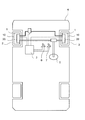
- FIG. 1 is an explanatory diagram of a vehicle including a wheel drive device according to an embodiment of the present invention.
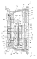
- FIG. 2 is an explanatory diagram of the wheel drive device according to the embodiment of the present invention.
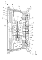
- FIG. 3 is an explanatory diagram of the wheel driving device according to the embodiment of the present invention.
- FIG. 4 is an explanatory diagram of the wheel drive device according to the embodiment of the present invention.
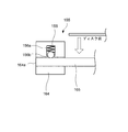
- FIG. 5 is an explanatory diagram of the urging mechanism according to the embodiment of the present invention.
- FIG. 1 is an explanatory diagram of a vehicle 4 including a wheel drive device 1 to which a multi-disc transmission according to an embodiment of the present invention is applied.
- the wheel drive device 1 is housed in a wheel 10 that constitutes the drive wheel 2 of the vehicle, and rotates the drive wheel 2 by the drive force of the motor 20 that is a drive force source. Let it run.
- the vehicle 4 is provided with a steering device 5 and controls the steering direction of the drive wheels 2.
- the wheel drive device 1 operates under the control of the control device 3 based on instructions such as operation of the steering device 5 by the driver, operation of the accelerator pedal 6 and the brake pedal 7.
- the vehicle 4 is provided with four wheels, but at least two may be configured as the drive wheels 2.
- 2 to 4 set the horizontal x-axis, the vertical y-axis, and the z-axis orthogonal to the x-axis y-axis, and show cross-sectional views in the x-axis plane, the y-axis plane, and the z-axis plane, respectively. .
- the wheel drive device 1 includes a wheel 10, a motor 20, a speed change mechanism 30, and a speed reduction mechanism 40.
- the wheel 10 is composed of a substantially cylindrical rim portion 10a for holding a tire and a disk-like disc portion 10b attached to a rotating hub 15 via bolts 16.
- a drive device such as a motor 20 accommodated in the housing 12 is housed inside the wheel 10.
- the housing 12 has a substantially cylindrical shape that is slightly smaller than the inner diameter of the rim portion 10 a of the wheel 10, and is connected to a suspension (not shown) of the vehicle 4.
- the motor 20 is configured as an axial gap motor in which disk-shaped stators 21 and 22 having coils and a disk-shaped rotor 23 having permanent magnets are arranged side by side in the rotation axis direction.
- the rotation of the rotor 23 that rotates when the motor 20 is driven is input to the speed change mechanism 30 from the input shaft 31 fixed to the rotor 23.
- the input shaft 31 extends from the motor 20 into the housing 12, and the end of the input shaft 31 is rotatably supported at the center of the hub 15 coupled to the disk portion 10b of the wheel 10 via a bearing 12a. .
- the speed change mechanism 30 is configured such that a disk-shaped primary disk 32 fixed to the input shaft 31 and a disk-shaped secondary disk 34 fixed to the output shaft 33 are brought into contact with each other by a pressing mechanism 35, whereby the input shaft 31.
- This is a multi-disc transmission that transmits the rotation of the motor to the output shaft 33 so as to be variable.
- the pressing mechanism 35 includes a rotation shaft 101 fixed to the housing 12 and a first and second pair of clamp arms (a front clamp arm 167 and a rear clamp arm 168) coupled to the rotation shaft 101 so as to be swingable. ) And a pressing force adjusting mechanism 132 provided on the free end side of the pair of clamp arms. The pressing force adjusting mechanism 132 adjusts the pressing force between the primary disk 32 and the secondary disk 34 in the pressing mechanism 35 by generating a pressing force in the pair of arms.
- the speed reduction mechanism 40 includes an external gear output gear 33a provided on the output shaft 33 and an internal gear 14 meshing with the external gear output gear 33a, and the rotation output from the output shaft 33 is transmitted to the internal gear 14. The reduced speed rotation is transmitted to the wheel 10 through the hub 15.
- the motor 20 includes a stator 21, a rotor 23, and a stator 22 arranged in this order in the axial direction.
- the motor 20 has a substantially cylindrical shape whose outer periphery matches the inner diameter of the opening of the housing 12, and is fixed to the inner peripheral side of the housing 12.
- the rotor 23 is arranged between the stators 21 and 22 arranged with a gap in the axial direction, and rotates by the action of the magnetic field generated by these.
- Each of the stators 21 and 22 is provided with a plurality of coils in the circumferential direction. Each coil is wound around an axis parallel to the rotation axis of the motor 20.
- the permanent magnet provided in the rotor 23 is configured as a ferrite magnet.
- the control device 3 rotates the rotor 23 by supplying current corresponding to the depression amount of the accelerator pedal 6 to the coils provided in the stators 21 and 22. As the rotor 23 rotates, the input shaft 31 rotates. The rotation of the input shaft 31 is input to the speed change mechanism 30.
- the speed change mechanism 30 includes a primary disk 32 fixed to the input shaft 31, a secondary disk 34 fixed to the output shaft 33, and a pressing mechanism 35.
- the primary disk 32 is configured by mounting two circular disks 32 a side by side in the axial direction of the input shaft, and rotates integrally with the input shaft 31.
- the two disks 32a are arranged at a predetermined interval.
- the outer peripheral end of the disk 32 a is disposed so as to be close to the output shaft 33.
- the secondary disk 34 is configured by a center disk 34 a and two side disks 34 b provided facing the both sides of the center disk 34 a arranged side by side in the axial direction of the output shaft 33, and integrated with the output shaft 33. Turns and turns.
- the center disk 34a and the side disk 34b are arranged at a predetermined interval.
- the outer peripheral ends of the center disk 34 a and the side disks 34 b are arranged so as to be close to the input shaft 31.
- the disk 32a of the primary disk 32 is arranged between the center disk 34a of the secondary disk 34 and the side disk 34b.
- the primary disk 32 and the secondary disk 34 form a disk overlap region where a part of the disk overlaps between the input shaft 31 and the output shaft 33.
- a gap is formed between the disk 32a of the primary disk 32 and the center disk 34a of the secondary disk 34 in a state where the pressing force by the pressing mechanism 35 does not act.
- the primary disk 32 and the secondary disk 34 are elastically deformed to come into contact with each other, and a torque transmission contact portion is formed.
- Rotation is transmitted from the input shaft 31 to the output shaft 33 by forming a torque transmission contact portion between the primary disk 32 and the secondary disk 34.
- a torque transmission contact portion By moving the torque transmission contact portion in the radial direction of the primary disk 32 and the secondary disk 34 in the disk overlapping region, the rotation of the input shaft 31 can be transmitted to the output shaft 33 in a variable speed manner.
- an axis connection line O indicated by a thick dotted line connects the axis of the input shaft 31 and the output shaft 33 and is orthogonal to the input shaft 31 and the output shaft 33.
- the torque transmission contact portion is formed on the shaft connection line O.
- the pressing mechanism 35 includes a pressing roller mechanism 130, a disk clamping mechanism 131, a pressing force adjusting mechanism 132, and a sliding actuator 133.
- the pressing roller mechanism 130 includes a pressing roller 160, a holding unit 161, a pressing roller shaft 162, a roller block 163, a guide block 164, a guide block shaft 165, and a guide block shaft 151.
- the pair of pressing roller mechanisms 130 are arranged on both sides of the primary disk 32 and the secondary disk 34 and are attached to the roller block 163.
- the roller block 163 is mounted between a guide block 164 formed in the vertical direction (y-axis direction) between the roller block 163 and the support member 25 provided in the horizontal direction (x-axis direction) on the inner periphery of the housing 12.
- a guide block shaft 151 extending in the direction of the connecting line O and a set of guide block shafts 165 are slidably attached.
- an urging mechanism 155 that urges the roller block 163 in a direction to separate the primary disk 32 and the secondary disk 34 from each other is provided.
- the urging mechanism 155 will be described in detail with reference to FIG.
- the disc clamp mechanism 131 includes a front clamp arm 167 and a rear clamp arm 168 as shown in FIG.
- the front clamp arm 167 and the rear clamp arm 168 are each slidably attached with a guide portion 166 on the lower side of the pressing roller mechanism 130.
- the front clamp arm 167 and the rear clamp arm 168 are moved in a direction in which the primary disk 32 and the secondary disk 34 are clamped with each other by the pressing force adjusting mechanism 132, thereby pressing the pressing roller 160 against the disk.
- the pressing force adjusting mechanism 132 moves the front clamp arm 167 and the rear clamp arm 168 in a direction to sandwich the primary disk 32 and the secondary disk 34 by the operation of the actuator 190.
- the control device 3 outputs a command signal so as to generate a pressing force corresponding to the torque to be transmitted, and the actuator 190 operates in response to the command signal, so that the pressing roller 160 presses according to the torque to be transmitted. It is pressed against the disc side by force. Thereby, the primary disk 32 and the secondary disk 34 are elastically deformed and brought into contact with each other to form a torque transmission contact portion, and the rotation of the input shaft 31 is transmitted to the output shaft 33.
- the pressing force adjusting mechanism 132 operates the actuator 190 in response to a command signal indicating that the pressing force from the control device 3 is zero, and the pressing roller 160 is pressed. Force is zero. Accordingly, the primary disk 32 and the secondary disk 34 are not elastically deformed, so that the driving force is not transmitted, and the rotation of the input shaft 31 is not transmitted to the output shaft 33.
- the sliding actuator 133 includes an electric motor 134 and a sliding mechanism 135.
- the sliding actuator 135 is moved forward and backward by operating the electric motor 134 according to a command signal from the control device 3, and is connected to the sliding mechanism 135.
- the pressing roller mechanism 130 is moved along the axial connection line O. As a result, the pressing roller 160 of the pressing roller mechanism 130 is moved in the direction of the axis connection line O to form a torque transmission contact portion at a position corresponding to the target gear ratio.
- An external gear 33a is provided at the end of the output shaft 33 on the disk portion 10b side.
- the external gear output gear 33 a meshes with the internal gear 14 fixed to the hub 15 coupled to the wheel 10 to rotate the internal gear 14.
- the external gear output gear 33a meshes with an idler gear 51 that is provided on the inner peripheral side of the internal gear 14 and is rotatably provided coaxially with the input shaft 31.
- the internal gear 14 and the idler gear 51 have the same rotation shaft, and there is an interval between the external gear 33a and the external gear 33a.
- the idler gear 51 is pivotally supported via a bearing 51 a so as to be rotatable with respect to the output shaft 33.
- a pinion 61a having substantially the same shape as the external gear output gear 33a meshes at a position different from that of the external gear output gear 33a.
- the pinion 61 a is provided on the disk portion 10 b side of the counter shaft 61.
- the external tooth output gear 33a of the output shaft 33 is provided at one point in the circumferential equal division point of the internal gear 14, and the pinion 61a of the counter shaft 61 is provided at another point in the circumferential equal division point of the internal gear 14.
- the external tooth output gear 33a and the pinion 61a are arranged in the diameter direction of the internal gear 14 with the input shaft 31 as the center, but more pinions 61a and counter shafts may be arranged.
- a bearing 17 is provided on a wall surface on the inner peripheral side of the housing 12 and on the disk portion 10b side, and the internal gear 14 is supported by the bearing 17 so as to be rotatable from the outer periphery.
- the internal gear 14 is fixed to the hub 15.
- the hub 15 is rotatably supported by the housing 12 via the internal gear 14 and the bearing 17.
- the disk portion 10 b of the wheel 10 is coupled to the hub 15 via a bolt 16.
- An oil seal 18 is provided between the hub 15 and the housing 12.
- the oil seal 18 prevents the lubricating oil from scattering from the bearing 17 and the like to the wheel 10 and the outside thereof.
- the secondary disk 34 fixed to the output shaft 33 is provided with a brake device 72.
- the brake device 72 imparts rotational resistance by sandwiching the center disk 34a and the two side disks 34b constituting the secondary disk 34, and brakes the rotation of the output shaft 33.
- a braking force is applied to the vehicle by braking the rotation of the output shaft 33.
- the brake device 72 controls the braking force of the wheel drive device 1 by applying a braking force by sandwiching the secondary disk 34 according to an instruction from the control device 3 according to, for example, the depression amount of the brake pedal by the driver.
- the wheel drive device 1 shifts the output of the motor 20 by the speed change mechanism 30, and the wheel 10 via the internal gear 14 provided on the inner side of the wheel 10 with the speed-changed rotation. It is the structure which is transmitted to.
- the rotation to the wheel 10 can be transmitted with a large reduction ratio, and the space in the inner diameter portion of the internal gear 14 is driven by the wheel. Since it can use for the component of the apparatus 1, the depth of a component can be formed flat, and the size and weight of the wheel drive device 1 can be reduced.
- the pressing force adjusting mechanism 132 outputs a command signal so as to generate a pressing force corresponding to the torque to be transmitted from the control device 3, and the actuator 190 operates by receiving the command signal.
- the pressing roller 160 is pressed toward the disc side with a pressing force corresponding to the torque to be transmitted.
- the primary disk 32 and the secondary disk 34 are elastically deformed and brought into contact with each other to form a torque transmission contact portion, and the rotation of the input shaft 31 is transmitted to the output shaft 33.
- the pressing force adjusting mechanism 132 operates the actuator 190 in response to a command signal indicating that the pressing force is zero from the control device 3, and the pressing roller 160 The pressing force becomes zero. Accordingly, the primary disk 32 and the secondary disk 34 are not elastically deformed, so that the driving force is not transmitted, and the rotation of the input shaft 31 is not transmitted to the output shaft 33.
- the actuator 190 controls the pressing force of the pressing roller 160 with zero, but since the control device 3 only controls the torque (pressing force) of the pressing roller 160, the primary disk 32 is actually controlled. And the secondary disk 34 is not sufficiently clear. In this case, between the disks, there may be a state in which these are kept in close contact with the lubricating oil in the wheel drive device 1. When the surfaces of the primary disk 32 and the secondary disk 34 are brought into close contact with each other by the lubricating oil, drag torque is generated.
- the following configuration is used to suppress drag torque between the disks.
- FIG. 5 is an explanatory diagram of the biasing mechanism 155 of the present embodiment.
- the pressing roller mechanism 130 is slidably supported by a guide block shaft 151 and a pair of guide block shafts 165 that extend in the direction of the axis connecting line O.
- Each of the guide block shafts 165 is attached to a pair of guide blocks 164 at both ends via a pair of urging mechanisms 155.
- the urging mechanism 155 includes a through hole 164a through which the guide block shaft 165 is inserted, and a ball plunger 156 that urges the guide block shaft 165.
- the ball plunger 156 includes a spring 156a and a ball 156b.
- the through hole 164a is formed in a shape slightly larger than the outer shape of the guide block shaft 165, and the guide block shaft 165 is parallel to the input shaft 31 and the output shaft 33 (z-axis direction) in the biasing mechanism 155. It is configured to be movable.
- a ball plunger 156 constituted by a spring 156a and a ball 156b biases the guide block shaft 165 in a direction in which the primary disk 32 and the secondary disk 34 are separated from each other.
- the pair of pressing rollers 160 are quickly separated in the direction separating from each other, and the primary disk 32 and the secondary disk 34 are separated from each other. They are separated quickly by the centrifugal force of the rotation.
- the speed change mechanism 30 of the present embodiment includes the input shaft 31 to which the rotation of the motor 20 that is a driving force source is input, the output shaft 33 that is disposed in parallel with the input shaft 31, and the input shaft 31.
- a pair of pressing rollers 160 that press the secondary disk 34 against each other, a pressing force adjusting mechanism 132 that applies a pressing force to the pair of pressing rollers 160, and a radius of the primary disk 32 and the secondary disk 34 in the overlapping region.
- Sliding actuator 133 to move in the direction
- the pair of pressing rollers 160 are moved from the primary disk 32 and the secondary disk 34 by the biasing force of the biasing mechanism 155. Is biased in the direction of separating them. As a result, contact between the primary disk 32 and the secondary disk 34 is released, and a sufficient clearance between the disks can be secured, so that drag torque can be suppressed, and transmission of torque can be suppressed when driving force is not transmitted.
- the pressing roller 160 is provided with a guide block shaft 165 that slidably supports the primary disk 32 and the secondary disk 34 in the radial direction, and the urging mechanism 155 includes the guide block shaft 165, the primary disk 32 and the secondary disk 34.
- the urging mechanism 155 includes the guide block shaft 165, the primary disk 32 and the secondary disk 34.
- a ball plunger 156 that urges them in a direction in which they are separated from each other.
- the urging mechanism 155 that urges the guide block shaft 165 includes the ball plunger 156.
- the urging mechanism 155 is not limited to this, and the guide block shaft 165 is not limited to the elastic member such as rubber or hydraulic pressure. May be energized.
Landscapes
- Engineering & Computer Science (AREA)
- General Engineering & Computer Science (AREA)
- Mechanical Engineering (AREA)
- Friction Gearing (AREA)
- Electric Propulsion And Braking For Vehicles (AREA)
Abstract
プライマリディスク(32)及びセカンダリディスク(34)が重合する重合領域においてプライマリディスク(32)及びセカンダリディスク(34)を互いに押し付け、プライマリディスク(32)からの駆動力をセカンダリディスク(34)に伝達可能とする一対の押付ローラ(130)と、一対の押付ローラ(130)に押付力を作用させる押付力発生機構(35)と、一対の押付ローラ(130)を重合領域においてプライマリディスク(32)及びセカンダリディスク(34)の半径方向に移動させる変速アクチュエータ(133)と、一対の押付ローラ(130)を、プライマリディスク(32)及びセカンダリディスク(34)を互いに離間させる方向に付勢する付勢機構(155)と、を備える。
Description
本発明は、マルチディスク変速機に関する。
JP2010-53995Aには、入力軸に設けられたプライマリディスクと出力軸に設けられたセカンダリディスクとを部分的に重ね合わせてディスク重合領域を設け、ディスク重合領域で両ディスクを一対の押付ローラで挟んで接触させることで、入力軸の回転を出力軸に伝達するマルチディスク変速機が開示されている。
マルチディスク変速機においては、一対の押付ローラが両ディスクを挟む位置を変更することによって変速が実現される。すなわち、両ディスクを挟む位置を、入力軸に近づければ変速比がLow側(変速比大側)に変化し、出力軸に近づければ変速比がHigh側(変速比小側)に変化する。
JP2010-53995Aに記載のマルチディスク変速機では、押付ローラが両ディスクを挟むことにより駆動力を伝達する。一方で、駆動力を伝達しない場合は押付ローラの押付力を解放するが、単に押付ローラの押付力をゼロにしただけでは、両ディスクの面同士が潤滑油により密着し、引き摺りトルクが発生してしまう。これにより、意図しない駆動力が発生することで、例えばホイール駆動装置のブレーキ機構にこのような変速機が設けられている場合には、必要以上のブレーキ力が発生してしまい、エネルギー効率が低下するという問題がある。
本発明は、このような技術的課題に鑑みてなされたもので、マルチディスク変速機において、駆動力の非伝達時に、トルクの伝達を抑制することを目的とする。
本発明のある態様によれば、駆動力源からの駆動力が入力される入力軸と、入力軸と平行に配置された出力軸と、入力軸に固定されたプライマリディスクと、出力軸に固定され、プライマリディスクに重合するように配設されたセカンダリディスクと、プライマリディスク及びセカンダリディスクが重合する重合領域においてプライマリディスク及びセカンダリディスクを互いに押し付け、プライマリディスクからの駆動力をセカンダリディスクに伝達可能とする一対の押付ローラと、一対の押付ローラに押付力を作用させる押付力調整機構と、一対の押付ローラを重合領域においてプライマリディスク及びセカンダリディスクの半径方向に移動させる変速アクチュエータと、一対の押付ローラを、プライマリディスク及びセカンダリディスクを互いに離間させる方向に付勢する付勢機構と、を備えることを特徴とする。
上記態様によれば、一対の押付ローラを両ディスクから離間させる場合は、付勢機構の付勢力により、一対の押付ローラが、プライマリディスク及びセカンダリディスクを離間させる方向へと付勢されるので、一対の押付ローラと、プライマリディスク及びセカンダリディスクとの間に付勢機構が無い場合に比べ十分なクリアランスが確保されるため、ディスク間の接触が解放されて引き摺りトルクが抑制され、駆動力の非伝達時にプライマリディスクとセカンダリディスクの間のトルクの伝達を抑制できる。
以下、図面を参照して本発明の実施形態について説明する。
図1は、本発明の実施形態のマルチディスク変速機が適用されるホイール駆動装置1を備える車両4の説明図である。
本実施形態のホイール駆動装置1は、車両の駆動輪2を構成するホイール10の内部に収装され、駆動力源であるモータ20の駆動力により駆動輪2を回転させることにより、車両4を走行させる。車両4にはステアリング装置5が備えられており、駆動輪2の操舵方向を制御する。ホイール駆動装置1は、運転者によるステアリング装置5の操作、アクセルペダル6、ブレーキペダル7の操作等の指示に基づいて、制御装置3の制御により動作する。
車両4は4つの車輪が備えられるが、少なくとも2つが駆動輪2として構成されていればよい。
図2から図4は、本実施形態のホイール駆動装置1の構成を示す説明図である。
図2から図4は、水平方向のx軸、垂直方向のy軸及びx軸y軸に直交するz軸を設定し、これらx軸平面、y軸平面及びz軸平面における断面図をそれぞれ示す。
ホイール駆動装置1は、ホイール10、モータ20、変速機構30及び減速機構40を備える。
ホイール10は、タイヤを保持する略円筒形状のリム部10aと、回転側のハブ15にボルト16を介して取付けられる円板状のディスク部10bとから構成される。ホイール10の内方には、ハウジング12に収容されたモータ20等の駆動装置が収装される。ハウジング12は、ホイール10のリム部10aの内径よりも僅かに小さい略円筒形状を有し、車両4の図示しないサスペンションに連結されている。
モータ20は、コイルを有する円板状のステータ21、22と、永久磁石を有する円板状のロータ23とが回転軸方向に並べて配置されるアキシャルギャップモータとして構成される。モータ20が駆動されることで回転するロータ23の回転は、ロータ23に固定された入力軸31から変速機構30へと入力される。
入力軸31は、モータ20からハウジング12内へと延設され、入力軸31の端部はホイール10のディスク部10bに結合されるハブ15の中央にベアリング12aを介して回転自在に支持される。
変速機構30は、入力軸31に固定された円板状のプライマリディスク32と、出力軸33に固定された円板状のセカンダリディスク34とを、押付機構35により接触させることで、入力軸31の回転を変速可能に出力軸33へと伝達するマルチディスク変速機である。
押付機構35は、ハウジング12に固定された回動軸101と、回動軸101にそれぞれ揺動可能に連結される第1及び第2の一対のクランプアーム(フロントクランプアーム167、リアクランプアーム168)と、一対のクランプアームの自由端側に設けられる押付力調整機構132とで構成される。押付力調整機構132は、一対のアームに押付力を発生させることで、押付機構35におけるプライマリディスク32とセカンダリディスク34との押付力を調整する。
減速機構40は、出力軸33に設けられた外歯出力ギヤ33aと外歯出力ギヤ33aに噛合する内歯ギヤ14とで構成されており、出力軸33から出力される回転を内歯ギヤ14により減速し、減速された回転がハブ15を介してホイール10に伝達される。
次に、ホイール駆動装置1の各構成を説明する。
モータ20は、ステータ21、ロータ23及びステータ22が順に軸方向に配置されて構成される。モータ20は、その外周がハウジング12の開口部の内径に適う略円筒形状を有し、ハウジング12の内周側に固定される。
ロータ23は、軸方向に間隙を存して配置されるステータ21、22の間に配置され、これらの発生する磁界の作用により回転する。ステータ21、22には、いずれも周方向に複数のコイルが備えられる。各コイルはモータ20の回転軸と平行な軸を中心として巻回される。本実施形態のモータ20は、ロータ23に備えられる永久磁石がフェライト磁石として構成される。
制御装置3は、ステータ21、22に備えられるコイルにアクセルペダル6の踏み込み量に応じた電流を供給することによりロータ23を回転させる。ロータ23が回転することにより、入力軸31が回転する。入力軸31の回転は変速機構30に入力される。
変速機構30は、入力軸31に固定されたプライマリディスク32と、出力軸33に固定されたセカンダリディスク34と、押付機構35とにより構成される。
プライマリディスク32は、2枚の円形のディスク32aが入力軸の軸方向に並べて取付けられて構成され、入力軸31と一体となって回転する。2枚のディスク32aは所定の間隔を設けて配置される。ディスク32aの外周端は出力軸33に近接するように配置される。
セカンダリディスク34は、センターディスク34aと、センターディスク34aの両面側に向かい合わせて設けた2枚のサイドディスク34bとが出力軸33の軸方向に並べて取付けられて構成され、出力軸33と一体となって回転する。センターディスク34aとサイドディスク34bとは所定の間隔を設けて配置される。センターディスク34a及びサイドディスク34bの外周端は入力軸31に近接するように配置される。
プライマリディスク32のディスク32aは、セカンダリディスク34のセンターディスク34aとサイドディスク34bとの間に配置される。プライマリディスク32とセカンダリディスク34とは、入力軸31と出力軸33との間でディスクの一部が重なり合うディスク重合領域を形成する。
ディスク重合領域において、プライマリディスク32のディスク32aとセカンダリディスク34のセンターディスク34aとの間には、押付機構35による押付力が作用しない状態では隙間が形成される。押付機構35による押付力が作用する状態では、プライマリディスク32とセカンダリディスク34とが弾性変形して接触し、トルク伝達接触部が形成される。
プライマリディスク32とセカンダリディスク34との間にトルク伝達接触部が形成されることにより、入力軸31から出力軸33に回転が伝達される。ディスク重合領域において、トルク伝達接触部をプライマリディスク32及びセカンダリディスク34の半径方向に移動させることで、入力軸31の回転を変速可能に出力軸33に伝達することができる。なお、図3において太点線で示す軸心連結線Oは、入力軸31と出力軸33との軸心を結び、入力軸31と出力軸33とに直交する線である。トルク伝達接触部は、軸心連結線O上に形成される。
押付機構35は、押付ローラ機構130、ディスククランプ機構131、押付力調整機構132及び摺動アクチュエータ133を備える。
押付ローラ機構130は、押付ローラ160、保持部161、押付ローラシャフト162、ローラブロック163、ガイドブロック164、ガイドブロックシャフト165及びガイドブロックシャフト151を備える。
一組の押付ローラ機構130は、プライマリディスク32及びセカンダリディスク34を挟んで両側に配置され、ローラブロック163に取付けられる。ローラブロック163は、ハウジング12の内周に水平方向(x軸方向)に備えられる支持部材25との間に垂直方向(y軸方向)に形成されたガイドブロック164の間に取付けられ、軸心連結線O方向に延設されるガイドブロックシャフト151と一組のガイドブロックシャフト165に摺動可能に取付けられる。
ガイドブロック164とガイドブロックシャフト165との間には、ローラブロック163をプライマリディスク32及びセカンダリディスク34を互いに離間させる方向に付勢する付勢機構155が備えられる。付勢機構155は、図5で詳述する。
ディスククランプ機構131は、図4に示すように、フロントクランプアーム167及びリアクランプアーム168を備える。フロントクランプアーム167及びリアクランプアーム168は、それぞれ押付ローラ機構130の下側にあるガイド部166が摺動可能に取付けられる。フロントクランプアーム167及びリアクランプアーム168は、押付力調整機構132により互いにプライマリディスク32及びセカンダリディスク34を挟持する方向に移動させられることで、押付ローラ160をディスクに押し付ける。
押付力調整機構132は、アクチュエータ190の動作により、フロントクランプアーム167及びリアクランプアーム168を互いにプライマリディスク32及びセカンダリディスク34を挟持する方向に移動させる。制御装置3からは、伝達すべきトルクに応じた押付力を発生するよう指令信号を出力し、指令信号をうけてアクチュエータ190が動作することで、押付ローラ160が伝達すべきトルクに応じた押付力でそれぞれディスク側に押し付けられる。これにより、プライマリディスク32とセカンダリディスク34とを弾性変形させ、これらを接触させることによりトルク伝達接触部が形成され、入力軸31の回転が出力軸33へと伝達される。
押付力調整機構132は、プライマリディスク32及びセカンダリディスク34の間で駆動力を伝達しない場合は、制御装置3からの押付力がゼロである指令信号によりアクチュエータ190が動作し、押付ローラ160は押付力がゼロとなる。これにより、プライマリディスク32とセカンダリディスク34とは弾性変形がなくなることで駆動力の伝達がなくなり、入力軸31の回転が出力軸33に伝達されなくなる。
摺動アクチュエータ133は、電動モータ134と摺動機構135とを備え、制御装置3からの指令信号により電動モータ134を動作させることで摺動機構135を進退させ、摺動機構135に連結される押付ローラ機構130を軸心連結線Oに沿って移動させる。これにより、押付ローラ機構130の押付ローラ160を軸心連結線O方向に移動させて、目標変速比に対応する位置にトルク伝達接触部を形成する。
出力軸33のディスク部10b側の端部には、外歯出力ギヤ33aが備えられる。外歯出力ギヤ33aはホイール10に結合されるハブ15に固定される内歯ギヤ14と噛合し、内歯ギヤ14を回転させる。
外歯出力ギヤ33aは、内歯ギヤ14の内周側にあって入力軸31と同軸に回転自在に備えられるアイドラギヤ51にも噛合する。内歯ギヤ14とアイドラギヤ51とは回転軸を同一とし、これらの間は外歯出力ギヤ33aが噛合する間隔を有する。アイドラギヤ51は、出力軸33に対して回転自在にベアリング51aを介して軸支される。
内歯ギヤ14とアイドラギヤ51との間は、外歯出力ギヤ33aとは異なる位置に外歯出力ギヤ33aと略同形状のピニオン61aが噛合する。ピニオン61aは、カウンタ軸61のディスク部10b側に備えられる。
出力軸33の外歯出力ギヤ33aは内歯ギヤ14の周方向等分割点の一点に備えられ、カウンタ軸61のピニオン61aは内歯ギヤ14の周方向等分割点の他点に備えられる。本実施形態では、入力軸31を中心として内歯ギヤ14の直径方向に外歯出力ギヤ33aとピニオン61aとを配置したが、さらに多くのピニオン61a及びカウンタ軸を配置してもよい。
ハウジング12の内周側であってディスク部10b側の壁面にはベアリング17が備えられ、内歯ギヤ14は、ベアリング17に外周から回転自在に支持される。内歯ギヤ14は、ハブ15に固定される。ハブ15は、内歯ギヤ14及びベアリング17を介してハウジング12に回転自在に支持される。ホイール10のディスク部10bはボルト16を介してハブ15に結合される。
ハブ15とハウジング12との間にはオイルシール18が備えられる。オイルシール18は、ベアリング17等から潤滑油がホイール10及びその外部へと飛散することを防止する。
出力軸33に固定されるセカンダリディスク34には、ブレーキ装置72が備えられる。ブレーキ装置72は、セカンダリディスク34を構成するセンターディスク34a及び二つのサイドディスク34bをそれぞれ挟持することにより回転抵抗を与え、出力軸33の回転を制動する。出力軸33の回転を制動することにより車両に制動力を与える。
ブレーキ装置72は、例えば運転者によるブレーキペダルの踏み込み量に応じて、制御装置3の指示により、セカンダリディスク34を挟持することにより制動力を与え、ホイール駆動装置1の制動力を制御する。
このように、本実施形態のホイール駆動装置1は、モータ20の出力を、変速機構30により変速させ、変速された回転をホイール10の内方に備えられた内歯ギヤ14を介してホイール10に伝達させる構成である。このように、ホイール10への回転の伝達を内歯ギヤ14により行うことにより、ホイール10への回転を大きな減速比により伝達することができると共に、内歯ギヤ14の内径部分のスペースをホイール駆動装置1の構成部品に用いることができるので、構成部品の奥行きを扁平に形成することができて、ホイール駆動装置1のサイズ及び重量を低減することができる。
次に、本実施形態の付勢機構155について、図5を参照して説明する。
前述のように、押付力調整機構132は、制御装置3からは伝達すべきトルクに応じた押付力を発生するように指令信号を出力し、指令信号をうけてアクチュエータ190が動作することで、押付ローラ160が伝達すべきトルクに応じた押付力でそれぞれディスク側に押付けられる。これにより、プライマリディスク32とセカンダリディスク34とを弾性変形させ、これらを接触させることによりトルク伝達接触部形成され、入力軸31の回転が出力軸33へと伝達される。
一方、プライマリディスク32及びセカンダリディスク34の間で駆動力を伝達しない場合は、押付力調整機構132は、制御装置3から押付力がゼロである指令信号によりアクチュエータ190が動作し、押付ローラ160は押付力がゼロとなる。これにより、プライマリディスク32とセカンダリディスク34とは弾性変形がなくなることで駆動力の伝達がなくなり、入力軸31の回転が出力軸33に伝達されなくなる。
このとき、アクチュエータ190は押付ローラ160の押付力をゼロでコントロールしているが、制御装置3は押付ローラ160のトルク(押付力)をコントロールしているだけであるため、実際にはプライマリディスク32とセカンダリディスク34との間のクリアランスが十分でない。この場合ディスク間において、ホイール駆動装置1内の潤滑油によりこれらの間が密着したままの状態となる場合がある。プライマリディスク32とセカンダリディスク34との面同士が潤滑油により密着すると、引き摺りトルクが発生してしまう。
本実施形態では、ディスク間の引き摺りトルクを抑制するために、次のように構成した。
図5は、本実施形態の付勢機構155の説明図である。
押付ローラ機構130は、軸心連結線O方向に延設されるガイドブロックシャフト151と一組のガイドブロックシャフト165に摺動可能に支持される。ガイドブロックシャフト165は、それぞれ、両端側の一組のガイドブロック164に対して一組の付勢機構155を介して取付けられる。
付勢機構155は、ガイドブロックシャフト165が挿通される貫通孔164aと、ガイドブロックシャフト165を付勢するボールプランジャ156とを備える。ボールプランジャ156は、バネ156a及びボール156bから構成される。
貫通孔164aは、ガイドブロックシャフト165の外周の形状よりも僅かに大きな形状に形成されおり、付勢機構155においてガイドブロックシャフト165が入力軸31及び出力軸33と平行方向(z軸方向)に移動可能に構成される。バネ156a及びボール156bにより構成されるボールプランジャ156は、ガイドブロックシャフト165を、プライマリディスク32及びセカンダリディスク34が離間する方向へと付勢する。
このような構成により、押付ローラ160を両ディスク側に押付けた場合は、付勢機構155のボールプランジャ156が縮退してガイドブロックシャフト165が、プライマリディスク32及びセカンダリディスク34を接触する方向へと移動する。
一方、押付ローラ160を両ディスクから離間させる場合は、付勢機構155のボールプランジャ156の付勢力により、ガイドブロックシャフト165が、プライマリディスク32及びセカンダリディスク34を離間させる方向へと付勢される(図5の矢印方向)。
ガイドブロックシャフト165がプライマリディスク32及びセカンダリディスク34を離間させる方向へと付勢されることにより、一対の押付ローラ160が互いに離間する方向へと速やかに離れると共に、プライマリディスク32及びセカンダリディスク34が、その回転の遠心力により、速やかに離間される。
これにより、押付ローラ160の押付力がゼロとなった場合には、プライマリディスク32とセカンダリディスク34との接触が解放され、付勢機構155が無い場合に比べて両ディスク間のクリアランスが十分に確保されるので、潤滑油が介在しても入力軸31の回転が出力軸33に伝達され難くなる。
以上説明したように、本実施形態の変速機構30は、駆動力源であるモータ20の回転が入力される入力軸31と、入力軸31と平行に配置された出力軸33と、入力軸31に固定されたプライマリディスク32と、出力軸33に固定され、プライマリディスク32に互いに重合するように配設されたセカンダリディスク34と、プライマリディスク32及びセカンダリディスク34が重合する重合領域においてプライマリディスク32及びセカンダリディスク34を互いに押し付ける一対の押付ローラ160と、一対の押付ローラ160に押付力を作用させる押付力調整機構132と、一対の押付ローラ160を重合領域においてプライマリディスク32及びセカンダリディスク34の半径方向に移動させる摺動アクチュエータ133と、一対の押付ローラ160を、プライマリディスク32及びセカンダリディスク34を互いに離間させる方向に付勢する付勢機構155と、を備えた。
本実施形態では、このように構成することにより、一方、押付ローラ160の押付力を解放した場合は、付勢機構155の付勢力により、一対の押付ローラ160が、プライマリディスク32及びセカンダリディスク34を離間させる方向へと付勢される。これにより、プライマリディスク32とセカンダリディスク34と接触が解放されてディスク間のクリアランスを十分に確保できるので、引き摺りトルクを抑制することができ、駆動力の非伝達時に、トルクの伝達を抑制できる。
押付ローラ160には、プライマリディスク32及びセカンダリディスク34の半径方向に摺動可能に支持するガイドブロックシャフト165が備えられ、付勢機構155は、ガイドブロックシャフト165を、プライマリディスク32及びセカンダリディスク34を互いに離間させる方向に付勢するボールプランジャ156により構成される。このように、簡易な構成によって、引き摺りトルクを抑制することができるので、マルチディスク変速機の製造コストを上昇させることがない。
以上、本発明の実施形態について説明したが、上記実施形態は本発明の適用例の一つを示したものに過ぎず、本発明の技術的範囲を上記実施形態の具体的構成に限定する趣旨ではない。
上記実施形態では、ガイドブロックシャフト165を付勢する付勢機構155を、ボールプランジャ156を備えて構成したが、これに限られるものではなく、例えばゴム等の弾性部材や油圧によってガイドブロックシャフト165を付勢するものであってもよい。
本願は、2014年6月12日に日本国特許庁に出願された特願2014-121800に基づく優先権を主張する。これらの出願のすべての内容は参照により本明細書に組み込まれる。
Claims (3)
- 駆動力源からの駆動力が入力される入力軸と、
前記入力軸と平行に配置された出力軸と、
前記入力軸に固定されたプライマリディスクと、
前記出力軸に固定され、前記プライマリディスクに重合するように配設されたセカンダリディスクと、
前記プライマリディスク及び前記セカンダリディスクが重合する重合領域において前記プライマリディスク及び前記セカンダリディスクを互いに押し付け、前記プライマリディスクからの前記駆動力を前記セカンダリディスクに伝達可能とする一対の押付ローラと、
一対の前記押付ローラに押付力を作用させる押付力調整機構と、
一対の前記押付ローラを前記重合領域において前記プライマリディスク及び前記セカンダリディスクの半径方向に移動させる変速アクチュエータと、
一対の前記押付ローラを、前記プライマリディスク及び前記セカンダリディスクを互いに離間させる方向に付勢する付勢機構と、
を備えるマルチディスク変速機。 - 請求項1に記載のマルチディスク変速機であって、
前記押付ローラには、前記プライマリディスク及び前記セカンダリディスクの半径方向に摺動可能に支持するシャフトが備えられ、
前記付勢機構は、前記シャフトを、前記プライマリディスク及び前記セカンダリディスクを互いに離間させる方向に付勢するボールプランジャにより構成されるマルチディスク変速機。 - ホイールの内方又はその近傍に配設されたモータと、
請求項1又は2に記載のマルチディスク変速機を備え、前記駆動源は、前記モータであるホイール駆動装置。
Priority Applications (1)
| Application Number | Priority Date | Filing Date | Title |
|---|---|---|---|
| JP2016527662A JP6298889B2 (ja) | 2014-06-12 | 2015-03-03 | マルチディスク変速機及びホイール駆動装置 |
Applications Claiming Priority (2)
| Application Number | Priority Date | Filing Date | Title |
|---|---|---|---|
| JP2014121800 | 2014-06-12 | ||
| JP2014-121800 | 2014-06-12 |
Publications (1)
| Publication Number | Publication Date |
|---|---|
| WO2015190137A1 true WO2015190137A1 (ja) | 2015-12-17 |
Family
ID=54833246
Family Applications (1)
| Application Number | Title | Priority Date | Filing Date |
|---|---|---|---|
| PCT/JP2015/056212 Ceased WO2015190137A1 (ja) | 2014-06-12 | 2015-03-03 | マルチディスク変速機及びホイール駆動装置 |
Country Status (2)
| Country | Link |
|---|---|
| JP (1) | JP6298889B2 (ja) |
| WO (1) | WO2015190137A1 (ja) |
Citations (5)
| Publication number | Priority date | Publication date | Assignee | Title |
|---|---|---|---|---|
| GB392917A (en) * | 1930-11-24 | 1933-05-24 | Eugen Mandler | Improvements in or relating to friction gears |
| JPH0193658A (ja) * | 1987-10-05 | 1989-04-12 | Fuji Heavy Ind Ltd | 車輛用無段変速装置 |
| JP2010053995A (ja) * | 2008-08-29 | 2010-03-11 | Jatco Ltd | 変速機 |
| JP2010241183A (ja) * | 2009-04-01 | 2010-10-28 | Toyota Motor Corp | インホイールモータ搭載車の車高調整機構 |
| JP2011030307A (ja) * | 2009-07-22 | 2011-02-10 | Toyota Motor Corp | 回転電機 |
-
2015
- 2015-03-03 WO PCT/JP2015/056212 patent/WO2015190137A1/ja not_active Ceased
- 2015-03-03 JP JP2016527662A patent/JP6298889B2/ja not_active Expired - Fee Related
Patent Citations (5)
| Publication number | Priority date | Publication date | Assignee | Title |
|---|---|---|---|---|
| GB392917A (en) * | 1930-11-24 | 1933-05-24 | Eugen Mandler | Improvements in or relating to friction gears |
| JPH0193658A (ja) * | 1987-10-05 | 1989-04-12 | Fuji Heavy Ind Ltd | 車輛用無段変速装置 |
| JP2010053995A (ja) * | 2008-08-29 | 2010-03-11 | Jatco Ltd | 変速機 |
| JP2010241183A (ja) * | 2009-04-01 | 2010-10-28 | Toyota Motor Corp | インホイールモータ搭載車の車高調整機構 |
| JP2011030307A (ja) * | 2009-07-22 | 2011-02-10 | Toyota Motor Corp | 回転電機 |
Also Published As
| Publication number | Publication date |
|---|---|
| JP6298889B2 (ja) | 2018-03-20 |
| JPWO2015190137A1 (ja) | 2017-04-20 |
Similar Documents
| Publication | Publication Date | Title |
|---|---|---|
| JP6475187B2 (ja) | 駆動装置 | |
| US11555538B2 (en) | Disconnector apparatus | |
| US9476470B2 (en) | Electro-mechanical brake | |
| KR100957329B1 (ko) | 전동식 브레이크 시스템용 디스크 브레이크 장치 | |
| WO2010110027A1 (ja) | インホイールモーター用ブレーキ装置 | |
| JP2014159837A (ja) | 車輪駆動装置 | |
| JP5907164B2 (ja) | 電磁クラッチ | |
| WO2011067813A1 (ja) | 無段変速機 | |
| JP6298889B2 (ja) | マルチディスク変速機及びホイール駆動装置 | |
| JP6784203B2 (ja) | 駆動装置 | |
| JP5965936B2 (ja) | マルチディスク変速機及びホイール駆動装置 | |
| JP6015462B2 (ja) | 電動式ディスクブレーキ装置の組付方法 | |
| JP2018118546A (ja) | 車両 | |
| JP2013200012A (ja) | ブレーキ装置及び動力伝達装置 | |
| JP6113676B2 (ja) | マルチディスク変速機及びホイール駆動装置 | |
| JP5432408B1 (ja) | 互いに逆回転する複数の大口径薄型の回転電機を電気自動車の駆動用モーターとして使う場合に適する変速装置 | |
| JP2015108426A (ja) | ホイール駆動装置 | |
| JP6057081B2 (ja) | 潤滑油供給装置 | |
| JP6117702B2 (ja) | マルチフリーディスク式クラッチ | |
| JP2005155871A (ja) | 高分子アクチュエータおよびクラッチ装置 | |
| JP2010090994A (ja) | 電動ブレーキ装置 | |
| JP2017198243A (ja) | 車両用無段変速機 | |
| JP5942877B2 (ja) | ベルト式無段変速機の制御装置 | |
| JP5371700B2 (ja) | デファレンシャル装置 | |
| JP2014137068A (ja) | 断続装置及びこの断続装置を用いた動力伝達装置及びこの動力伝達装置を用いた車両用駆動装置 |
Legal Events
| Date | Code | Title | Description |
|---|---|---|---|
| 121 | Ep: the epo has been informed by wipo that ep was designated in this application |
Ref document number: 15806048 Country of ref document: EP Kind code of ref document: A1 |
|
| ENP | Entry into the national phase |
Ref document number: 2016527662 Country of ref document: JP Kind code of ref document: A |
|
| NENP | Non-entry into the national phase |
Ref country code: DE |
|
| 122 | Ep: pct application non-entry in european phase |
Ref document number: 15806048 Country of ref document: EP Kind code of ref document: A1 |