WO2015190050A1 - 運転支援装置 - Google Patents
運転支援装置 Download PDFInfo
- Publication number
- WO2015190050A1 WO2015190050A1 PCT/JP2015/002659 JP2015002659W WO2015190050A1 WO 2015190050 A1 WO2015190050 A1 WO 2015190050A1 JP 2015002659 W JP2015002659 W JP 2015002659W WO 2015190050 A1 WO2015190050 A1 WO 2015190050A1
- Authority
- WO
- WIPO (PCT)
- Prior art keywords
- obstacle
- arrangement
- vehicle
- parking area
- unit
- Prior art date
- Legal status (The legal status is an assumption and is not a legal conclusion. Google has not performed a legal analysis and makes no representation as to the accuracy of the status listed.)
- Ceased
Links
Images




Classifications
-
- G—PHYSICS
- G08—SIGNALLING
- G08G—TRAFFIC CONTROL SYSTEMS
- G08G1/00—Traffic control systems for road vehicles
- G08G1/16—Anti-collision systems
- G08G1/168—Driving aids for parking, e.g. acoustic or visual feedback on parking space
-
- B—PERFORMING OPERATIONS; TRANSPORTING
- B62—LAND VEHICLES FOR TRAVELLING OTHERWISE THAN ON RAILS
- B62D—MOTOR VEHICLES; TRAILERS
- B62D15/00—Steering not otherwise provided for
- B62D15/02—Steering position indicators ; Steering position determination; Steering aids
- B62D15/027—Parking aids, e.g. instruction means
-
- B—PERFORMING OPERATIONS; TRANSPORTING
- B62—LAND VEHICLES FOR TRAVELLING OTHERWISE THAN ON RAILS
- B62D—MOTOR VEHICLES; TRAILERS
- B62D15/00—Steering not otherwise provided for
- B62D15/02—Steering position indicators ; Steering position determination; Steering aids
- B62D15/027—Parking aids, e.g. instruction means
- B62D15/028—Guided parking by providing commands to the driver, e.g. acoustically or optically
-
- G—PHYSICS
- G08—SIGNALLING
- G08G—TRAFFIC CONTROL SYSTEMS
- G08G1/00—Traffic control systems for road vehicles
- G08G1/16—Anti-collision systems
- G08G1/165—Anti-collision systems for passive traffic, e.g. including static obstacles, trees
-
- G—PHYSICS
- G08—SIGNALLING
- G08G—TRAFFIC CONTROL SYSTEMS
- G08G1/00—Traffic control systems for road vehicles
- G08G1/16—Anti-collision systems
- G08G1/166—Anti-collision systems for active traffic, e.g. moving vehicles, pedestrians, bikes
Definitions
- This disclosure relates to a driving assistance device (Driving Assistance Apparatus) that notifies the presence of an obstacle.
- Driving Assistance Apparatus Driving Assistance Apparatus
- a driving assistance device that detects an obstacle by an obstacle sensor such as a camera or a sonar provided in a vehicle and notifies the presence of the obstacle is known.
- Patent Document 1 the presence or absence of obstacles around the vehicle is determined based on the output signals of clearance sonar provided at the front and rear parts of the vehicle, and the approach to obstacles in the vicinity of the vehicle is determined.
- a driving support device that performs notification by buzzer sounding when detected is disclosed.
- a stationary obstacle (hereinafter referred to as a stationary object) that must always be in proximity to a parking area such as a home where parking and departure are frequently performed every time parking or departure is performed. If it exists, even if the driver has already learned the presence of the stationary object, the presence of the stationary object is notified every time parking or departure.
- the purpose of this disclosure is to make the driver aware of the presence of non-stationary obstacles in the vicinity of the parking area, even when there are stationary obstacles that must always be in close proximity each time parking or leaving. It is an object of the present invention to provide a driving support device that makes it easy.
- a driving support device including a notification unit that notifies a vehicle driver is provided so as to include an arrangement memory, an arrangement acquisition unit, and an obstacle identification unit.
- the arrangement memory stores past arrangements of obstacles around the target parking area.
- the arrangement acquisition unit acquires the current arrangement of obstacles around the parking area when driving around the parking area, which is at least one of driving the vehicle to enter the parking area and driving driving from the parking area.
- the obstacle identification unit is a non-stationary obstacle around the parking area based on the difference between the past obstacle arrangement stored in the arrangement memory and the current obstacle arrangement acquired by the arrangement acquisition unit. Identify unsteady obstacles that are
- the notification unit performs notification that indicates the presence of the unsteady obstacle specified by the obstacle specifying unit.
- the notifying unit notifies the presence of the non-steady obstacle identified by the obstacle identifying unit. Even if there is a stationary obstacle that does not get the result and the attention to the obstacle tends to decrease due to the familiarity with the obstacle, it is easy for the driver to notice the presence of the obstacle that is not stationary. can do.
- FIG. 1st embodiment shows an example of a schematic structure of the driving assistance system of 1st embodiment.
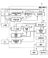
- Block diagram showing an example of a schematic configuration of a driving assistance ECU
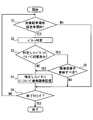
- the flowchart which shows an example of the flow of the obstacle learning process in driving assistance ECU
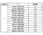
- the figure which shows an example of the correspondence of the pattern of the parking direction of a vehicle with respect to a target parking area, and a captured image
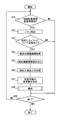
- Flowchart showing an example of the flow of parking vehicle support processing in the driving support ECU
- FIG. 1 Schematic diagram showing an example when there is no unsteady object around the target parking area
- the schematic diagram which shows the example in case an unsteady thing exists in the circumference
- the flowchart which shows an example of the flow of the alerting
- the block diagram for demonstrating the schematic structure of the driving assistance ECU of a 2nd modification.
- the figure which shows an example of the correspondence of the pattern of the parking direction of a vehicle, and a captured image according to a driver and object parking area.
- FIG. 1 is a diagram illustrating an example of a schematic configuration of a driving support system 100 to which the present disclosure is applied.
- the driving support system 100 is mounted on a vehicle and includes a camera 1, a vehicle state sensor group 2, a navigation device 3, a display device 4, an audio output device 5, and a driving support ECU 6 as shown in FIG. Yes.
- a vehicle equipped with the driving support system 100 is also referred to as a host vehicle or a subject vehicle.
- Camera 1 is installed in a vehicle and images the periphery of the vehicle.
- the camera 1 is also referred to as an obstacle sensor or an imaging device.
- the camera 1 a front camera that captures a predetermined angular range in front of the vehicle including a corner portion at the front of the vehicle, and a rear camera that captures a predetermined angular range in the rear of the vehicle that includes a corner portion at the rear of the vehicle.
- Vehicle state sensor group 2 is a group of various sensors that detect the vehicle state of the vehicle.
- the vehicle state sensor group 2 includes, for example, a vehicle speed sensor that detects the vehicle speed of the vehicle, a shift position sensor that detects the shift position of the vehicle, and a steering angle sensor that detects the steering angle of the vehicle.
- the navigation device 3 includes a position detector 31 and a map DB (database) 32.
- the position detector 31 sequentially detects the current position of the vehicle using, for example, a positioning system that detects the current position of the vehicle based on radio waves from a positioning satellite.
- the current position of the vehicle is, for example, the position of the center of the rear wheel axle of the vehicle and is represented by latitude / longitude coordinates.
- the map DB 32 stores map data including road data composed of node data and link data.
- a link is a link between nodes when each road on the electronic map is divided by a plurality of nodes such as intersections, branches, and joining points.
- the display device 4 displays text and images in accordance with instructions from the driving support ECU 6.
- the display device 4 is capable of full color display and can be configured using a liquid crystal display or the like.
- the display device 4 may be configured to use a display provided on an instrument panel or the like, or may be configured to use HUD (Head-Up Display).
- the audio output device 5 is composed of a speaker or the like, and outputs audio according to instructions from the driving support ECU 6.
- the display device 4 or the audio output device 5 is also referred to as a notification device.
- the driving support ECU 6 is mainly configured as a microcomputer, and each includes a known CPU, a memory such as a ROM and a RAM, an I / O, and a bus connecting them.
- the driving assistance ECU 6 executes various processes based on various information input from the camera 1, the vehicle state sensor group 2, and the navigation device 3. This driving assistance ECU 6 is also referred to as a driving assistance device.
- the driving support ECU 6 may be configured in hardware by one or a plurality of ICs.
- the driving assistance ECU 6 includes a captured image acquisition unit 61, a target parking area identification unit 62, a parking area memory 63, a learning determination unit 64, a pattern identification unit 65, an arrangement memory 66, an arrangement storage unit 67, and an assistance.
- a determination unit 68, an old and new comparison unit 69, an obstacle specifying unit 70, a proximity detection unit 71 (also referred to as a detection unit), and a notification unit 72 (also referred to as a notification processing unit 72) are provided.
- the memory is also referred to as a storage device or a storage device.
- the storage unit is also referred to as a storage processing unit.
- the captured image acquisition unit 61 sequentially acquires captured images captured by the camera 1.
- the target parking area specifying unit 62 specifies a parking area (hereinafter referred to as a target parking area) to be supported at the time of parking or departure, and stores the position of the specified target parking area in the parking area memory 63.
- the position of the target parking area is represented by, for example, latitude / longitude coordinates.
- the position registered as the user's home in the navigation device 3 may be specified as the target parking area.
- the driving assistance ECU 6 may determine that the vehicle is parked based on the fact that the vehicle state sensor group 2 detects that the shift position has become the parking position.
- the parking area memory 63 stores them. The positions of a plurality of target parking areas are stored.
- the learning determination unit 64, the pattern specification unit 65, the arrangement memory 66, the arrangement storage unit 67, the support determination unit 68, the old and new comparison unit 69, the obstacle specification unit 70, the proximity detection unit 71, and the notification unit 72 will be described in detail later. To do.
- the obstacle learning process in the driving support ECU 6 will be described with reference to the flowchart of FIG.
- the flowchart or the process of the flowchart described in the present disclosure includes a plurality of sections (or referred to as steps), and each section is expressed as, for example, S1. Further, each section can be divided into a plurality of subsections, while a plurality of sections can be combined into one section. Further, each section can be referred to as a device, a module.
- each of the above sections or a combination thereof includes not only (i) a section of software combined with a hardware unit (eg, a computer), but also (ii) hardware (eg, an integrated circuit, As a section of (wiring logic circuit), it can be realized with or without the function of related devices.
- the hardware section can be included inside the microcomputer.
- the obstacle learning process is a process for storing the arrangement of obstacles around the target parking area. As an example, the flowchart of FIG. 3 is started when the ignition power supply of the vehicle is turned on.
- the learning determination unit 64 determines whether the vehicle has started either parking in the target parking area or leaving the target parking area (hereinafter referred to as parking).
- parking the distance between the current position of the vehicle and the position of the target parking area stored in the parking area memory 63 is less than a predetermined distance such as 15 m, and the vehicle state sensor group 2 detects the vehicle.
- the shift position is not a parking position and the vehicle speed of the vehicle detected by the vehicle state sensor group 2 is, for example, less than or equal to a slow vehicle speed, it is determined that the vehicle has started parking in the target parking area. do it.
- the current position of the vehicle and the position of the target parking area are less than the predetermined distance, and the vehicle shift position detected by the vehicle state sensor group 2 has moved from the parking position to the forward position or the reverse position. In such a case, it may be determined that the vehicle has started departure from the target parking area.
- a configuration in which the steering angle of the vehicle detected by the vehicle state sensor group 2 is changed by a predetermined value or more may be added as a condition.
- the pattern specifying unit 65 specifies a pattern according to the vehicle situation.
- the following description will be given by taking as an example the case where the pattern of the parking direction of the vehicle with respect to the target parking area is specified. If the pattern of the parking direction of the vehicle with respect to the target parking area is specified from the current position of the vehicle, the traveling direction of the vehicle obtained from the current position of the vehicle obtained sequentially, link data, and the target parking area, Good.
- FIG. 4 is a diagram illustrating an example of a correspondence relationship between the pattern of the parking direction of the vehicle with respect to the target parking area and the captured image stored in the arrangement memory 66 for each target parking area.
- FIG. 4 shows an example of the correspondence relationship between the pattern of the parking direction of the vehicle and the captured image for the target parking area C.
- the arrangement storage unit 67 determines whether the captured image has been stored in the arrangement memory 66 for the pattern specified in S2. In the past obstacle learning process, when the captured image for the corresponding pattern is stored, the captured image is already stored in the arrangement memory 66 for the pattern specified in S2. On the other hand, when the captured image for the corresponding pattern has not been stored, such as when the obstacle learning process is executed for the first time, the captured image has not been stored in the placement memory 66 for the pattern specified in S2.
- the process proceeds to S4.
- the captured image acquisition unit 61 acquires a captured image.
- storage part 67 matches the acquired captured image with the pattern specified by S2, and memorize
- the captured image acquisition unit 61 acquires a captured image obtained by capturing the traveling direction of the vehicle with the camera 1. That is, a captured image of the front camera is acquired when moving forward, and a captured image of the rear camera is acquired when moving backward.
- both patterns of “Entering from the right direction backward” and “Entering from the right direction” both patterns of “Entering from the left direction and entering backward” and “Entering from the left direction”
- a common captured image may be stored for the other pattern.
- the process proceeds to S5.
- the arrangement storage unit 67 determines whether or not to update the captured image stored in the arrangement storage unit 67 in association with the pattern specified in S2.
- the update is performed when an unsteady non-stationary object is not identified from the captured image acquired by the captured image acquisition unit 61 in S27 of a parking vehicle support process described later that is executed in parallel with the obstacle learning process. What is necessary is just to set it as the structure determined to be.
- Non-stationary obstacles are also referred to as non-stationary obstacles or transitional obstacles.
- an obstacle that is stationary is also referred to as a stationary obstacle or a non-transition obstacle.
- the process moves to S4, where the arrangement storage unit 67 associates the captured image acquired by the captured image acquisition unit 61 with the pattern specified in S2, and the arrangement storage unit 67 The captured image is updated by storing the information in 66 by overwriting.
- the process proceeds to S6.
- S6 when it is the end timing of the obstacle learning process (S6: YES), the obstacle learning process is ended. If it is not the end timing of the obstacle learning process (S6: NO), the process returns to S1 and is repeated.
- the end timing of the obstacle learning process for example, when the current position of the vehicle and the position of the target parking area stored in the parking area memory 63 are equal to or more than the predetermined distance described above, or the ignition power source of the vehicle When is turned off.
- the parked vehicle support process is a process of notifying an obstacle close to the vehicle when parked in the target parking area.
- the flowchart of FIG. 5 is started when the ignition power of the vehicle is turned on, and is executed in parallel with the obstacle learning process described above.
- the support determination unit 68 determines whether the vehicle has started either parking in the target parking area or leaving the target parking area (that is, parking). Determine whether. And when it determines with having started parking (S21: YES), it moves to S22. On the other hand, if it is determined that parking is not started (S21: NO), the process proceeds to S29.
- the pattern specifying unit 65 specifies a pattern corresponding to the vehicle condition in the same manner as in the process of S2 described above.
- the pattern of the parking direction of the vehicle with respect to the target parking area is specified.
- any one of the learning determination unit 64 and the support determination unit 68 may have the other function.
- the arrangement storage unit 67 determines whether or not a captured image is stored in the arrangement memory 66 for the combination of the target parking area determined to start parking in S21 and the pattern specified in S22. Specifically, in the past obstacle learning process, when a captured image for the corresponding pattern has been stored, it is determined that there is a storage in the arrangement memory 66, and the captured image for the corresponding pattern is stored. If not, it is determined that there is no storage in the arrangement memory 66. If it is determined that there is memory (S23: YES), the process proceeds to S24, and if it is determined that there is no memory (S23: NO), the process proceeds to S29.
- the captured image acquisition unit 61 acquires the current captured image. Therefore, the captured image acquisition unit 61 is also referred to as an arrangement acquisition unit.
- the past captured image stored in association with the pattern specified in S22 is read from the arrangement memory 66.
- the current captured image acquired in S24 and the past captured image read from the arrangement memory 66 in S25 are captured images having the same pattern in the parking direction of the vehicle with respect to the target parking area when captured.
- the captured image is stored in the placement memory 66 in S4 of the obstacle learning process that is executed in parallel with the parked vehicle support process
- the captured image is stored after S25.
- the captured image is stored in the arrangement memory 66 in the past obstacle learning process rather than the obstacle learning process that is executed in parallel with the parked vehicle support process. Will be read out.
- the new and old comparison unit 69 compares the current captured image acquired in S24 with the past captured image read from the arrangement memory 66 in S25, and detects a difference between the captured images.
- the difference between the captured images may be detected by subtracting the past captured image from the current captured image in the same manner as the known temporal difference image method.
- what is necessary is just to set it as the structure which detects a thing more than the range of an error as a difference about a difference.
- the error referred to here includes an error of about the difference between captured images that may be caused by a deviation of the travel locus even if the pattern of the parking direction of the vehicle is the same. According to this, even if there is a deviation between the travel trajectory when the past captured image is obtained and the travel trajectory when the current captured image is obtained, the difference due to this deviation is determined as the difference between the captured images. This eliminates the need for detection and improves the specific accuracy of unsteady objects, which will be described later.
- the current captured image acquired in S24 and the past captured image read from the arrangement memory 66 in S25 are captured images having the same pattern of the parking direction of the vehicle with respect to the target parking area when captured, Since the imaging positions are substantially the same, the stationary obstacles should match in both captured images. Therefore, the difference between the captured images can be easily detected by subtracting the past captured image from the current captured image.
- the past captured image is subtracted from the current captured image after removing the influence of the shift. It is good also as a structure. For example, a plurality of feature points common to the current captured image and a past captured image are detected, and the captured image is subjected to deformation such as enlargement / reduction or rotation so that the positions of the plurality of feature points overlap. Thus, a configuration in which the influence of the shift in the imaging direction and the imaging position is removed may be adopted.
- a non-stationary obstacle hereinafter referred to as an unsteady object
- a stationary obstacle hereinafter referred to as a stationary object
- a distance distribution obtained from a parallax of a current captured image of a stereo camera by known stereo image processing and an original image
- a plurality of three-dimensional images in the captured image by known recognition processing are used.
- the distance between the vehicle and the obstacles is also detected.
- those present at the position of the difference detected at S26 are identified as non-stationary objects, and those other than the position of the difference detected at S26 are identified as stationary objects.
- the obstacle identifying unit 70 sequentially detects the distance between the vehicle and the stationary object or the unsteady object based on the distance image obtained from the captured image sequentially acquired by the captured image acquisition unit 61.
- the obstacle identifying unit 70 once identifies a stationary object or an unsteady object, tracks the position of the stationary object or the unsteady object in the captured image by a known area tracking process, The distance between the vehicle and the stationary object or the unsteady object may be sequentially detected without specifying the unsteady object.
- the proximity detection unit 71 determines whether the obstacle closest to the vehicle is an unsteady object from the distance between the vehicle sequentially detected by the obstacle specifying unit 70 and the steady or unsteady object. . If it is determined that the obstacle closest to the vehicle is an unsteady object (S281: YES), the process proceeds to S282. On the other hand, when it is determined that the obstacle closest to the vehicle is not an unsteady object (S281: NO), the process proceeds to S284. As an example, when an unsteady object is not identified by the obstacle identifying unit 70, or when an unsteady object is identified but the obstacle closest to the vehicle is a stationary object, the obstacle closest to the vehicle is non-steady. It is determined that it is not a stationary object.
- an obstacle that is predicted not to contact the vehicle even if it travels as it is is not targeted even if it approaches, and only an obstacle that is predicted to contact the vehicle if it proceeds as it is Good.
- the process proceeds to S283.
- the process proceeds to S286.
- the set distance here is a distance that can be arbitrarily set according to the vehicle speed of the vehicle, for example, and is a distance necessary to avoid at least contact with an obstacle.
- the notification unit 72 instructs the display device 4 and the audio output device 5 to notify that the presence of an unsteady object (that is, an unsteady obstacle) is present.
- an unsteady object that is, an unsteady obstacle
- text such as “There is an obstacle at a different position than usual” is displayed, sound is output, or a warning sound of a different type from the warning sound that indicates the presence of a stationary object is output.
- a warning sound of a different type from the warning sound that indicates the presence of a stationary object is output.
- the notification that the presence of the unsteady object is present is made according to the distance between the vehicle and the unsteady object approaching, such as shortening the cycle of the warning sound as the distance between the vehicle and the unsteady object approaches. It is good also as composition changed.
- S284 when it is determined that the obstacle closest to the vehicle is not an unsteady object, when the distance between the stationary object determined to be closest to the vehicle and the vehicle is equal to or less than the set distance (S284: YES). , The process proceeds to S285. On the other hand, when the distance between the stationary object determined to be closest to the vehicle and the vehicle is longer than the set distance (S284: NO), the process proceeds to S286.
- the set distance here may be the same distance as S282 or a different distance from S282.
- the set distance in S284 is It is preferable that the distance is shorter than the set distance in S282.
- the notification unit 72 instructs the display device 4 and the audio output device 5 to notify that there is a stationary object (that is, a stationary obstacle).
- a stationary object that is, a stationary obstacle.
- notification there is an example of outputting a warning sound of a different type from a warning sound when indicating the presence of an unsteady object.
- a stationary object is used rather than a warning sound when indicating the presence of an unsteady object. It is preferable to make the configuration less noticeable, for example, by lowering the volume of a warning sound when indicating the presence of the.
- the support determination unit 68 determines whether or not the vehicle has completed parking. As an example, when the current position of the vehicle and the position of the target parking area are equal to or greater than the predetermined distance described above, it is determined that the vehicle has started departure, and the vehicle is moved when the vehicle shift position becomes the parking position. What is necessary is just to set it as the structure which determines with having completed parking. And when it determines with having completed the parking vehicle (S286: YES), it moves to S29. On the other hand, if it is determined that parking is not completed (S286: NO), the process returns to S281 and the process is repeated.
- S29 if it is the end timing of the parking car support process (S29: YES), the parking car support process is ended. Moreover, when it is not the completion
- An example of the end timing of the parked vehicle support process is when the ignition power of the vehicle is turned off.
- FIG. 7 is a schematic diagram illustrating an example in which an unsteady object does not exist around the target parking area
- FIG. 8 illustrates an example in which an unsteady object exists around the same target parking area as FIG. It is a schematic diagram shown. 7 and 8, A represents a vehicle, B represents a stationary object, C represents a target parking area, and D in FIG. 8 represents an unsteady object.
- a notification indicating the presence of the stationary object when approaching the stationary object Will be done.
- FIG. 7 if a situation in which there is no non-stationary object around the target parking area continues, a similar notification will be performed every time the vehicle is parked, and a notification indicating the presence of the stationary object
- the driver may become accustomed to the driver, and the driver may not pay attention to the notification indicating the presence of the stationary object.
- the driving support system 100 of the first modification is the same as the driving support system 100 of the first embodiment, except that the notification-related processing in the parking car support processing is partially different.
- the proximity detector 71 determines whether or not the obstacle closest to the vehicle is an unsteady object, as in S281 described above.
- the process proceeds to S282a.
- the process proceeds to S284a.
- the processing from S282a to S284a is the same as the processing of S282 to S283 and S286 described above.
- the captured image corresponding to the pattern according to the vehicle situation is stored in the arrangement memory 66 for each target parking area, and the past captured image corresponding to the pattern according to the target parking area and the vehicle situation is arranged.
- the configuration for reading from the memory 66 is shown, the configuration is not necessarily limited thereto.
- a captured image corresponding to a pattern corresponding to a vehicle condition for each driver and target parking area is stored in the arrangement memory 66, and a past captured image corresponding to a pattern corresponding to the driver, the target parking area, and the vehicle condition is stored.
- a configuration for reading from the arrangement memory 66 (hereinafter, second modification) may be adopted. Below, this 2nd modification is demonstrated.
- the driving support system 100 according to the second modified example is provided with a driver specifying unit 73 that specifies the driver in the driving support ECU 6, and except that the obstacle learning process and the parking car support process are partially different. This is the same as the driving support system 100 of the embodiment.
- the driving assistance ECU 6 of the second modified example includes a captured image acquisition unit 61, a target parking area identification unit 62, a parking area memory 63, a learning determination unit 64, a pattern identification unit 65, an arrangement memory 66, an arrangement storage unit 67, and an assistance determination unit. 68, an old and new comparison unit 69, an obstacle identification unit 70, a proximity detection unit 71, a notification unit 72, and a driver identification unit 73.
- the driver specifying unit 73 specifies a driver who is driving the vehicle.
- a weight scale or pressure sensor provided in the seating portion of the driver's seat is used as the vehicle state sensor group 2, and an individual driver is determined based on the weight measured by the weight scale and the detection value of the pressure sensor. What is necessary is just to set it as the structure to identify.
- the configuration may be such that an individual driver is specified from the ID received from the electronic key.
- the pattern specifying unit 65 specifies the pattern according to the vehicle situation, and the driver specifying unit 73. Identifies the driver driving the vehicle.
- the arrangement storage unit 67 stores the captured image acquired by the captured image acquisition unit 61 in the arrangement memory 66 in association with the pattern specified by the pattern specifying unit 65 and the driver specified by the driver specifying unit 73. Note that the captured image is stored in the arrangement memory 66 in the same manner as the obstacle learning process in the first embodiment for the combination of the pattern specified by the pattern specifying unit 65 and the driver specified by the driver specifying unit 73. This is performed when the arrangement storage unit 67 determines that the image has not been stored in the arrangement memory 66 or the captured image needs to be updated.
- the captured image is stored in the arrangement memory 66 in a pattern according to the situation of the vehicle for each driver (see X and Y in FIG. 11) and parking area (see C ⁇ b> 1 and C ⁇ b> 2 in FIG. 11). It is done in association.
- FIG. 11 shows an example in which the pattern of the parking direction of the vehicle with respect to the target parking area is used as the pattern according to the situation of the vehicle.
- the wife's parents 'parking area corresponds to the target parking area, but for the husband, the wife's parents' parking area does not correspond to the target parking area There are cases.
- the pattern specifying unit 65 uses the pattern specifying unit 65 to specify a pattern according to the vehicle situation.
- the driver specifying unit 73 specifies a driver who is driving the vehicle.
- the captured image is stored in the arrangement memory 66 and the arrangement storage unit If determined to be 67, the captured image is read as a past captured image. Then, the new and old comparison unit 69 compares the past captured image and the current captured image acquired by the captured image acquisition unit 61 to detect a difference between the captured images.
- ⁇ Summary of second modification> When a plurality of drivers use the same vehicle, there may be a parking area that is a target parking area for a certain driver but is not a target parking area for another driver. Even in such a situation, according to the second modified example, since the past captured image of the target parking area is stored for each driver, it is possible to receive parking assistance according to the target parking area for each driver. become.
- the pattern in the parking direction of the vehicle with respect to the target parking area is shown as an example of the pattern according to the vehicle situation, but this is not necessarily limited thereto.
- a pattern according to the situation of a vehicle it is good also as a structure (henceforth a 3rd modification) using a time zone and a weather pattern.
- the time zone and weather pattern there is a change that makes it impossible to recognize the same obstacle on the image recognition, such as pattern division such as day or night, or pattern division such as sunny, cloudy, rainy or snowy
- pattern division such as day or night
- pattern division such as sunny, cloudy, rainy or snowy
- the pattern may be divided by the above.
- the configuration of the third modified example it becomes possible to identify non-stationary objects from captured images of the same current and past conditions such as time zone and weather, so when conditions such as time zone and weather are different It is possible to identify the unsteady object with higher accuracy by eliminating the influence of the erroneous determination that occurs.
- the distance of the vehicle to the target parking area is significantly different, the number of obstacles reflected in the current captured image and the past captured image will differ even if the number of obstacles actually present is the same between the current and past In other words, the specific accuracy of unsteady objects may be reduced.
- the configuration of the fourth modified example it is possible to specify an unsteady object from the captured images of the present and the past with the same condition of the distance of the vehicle to the target parking area.
- the influence of erroneous determination that occurs when the distance of the vehicle to the region is significantly different can be eliminated, and the unsteady object can be specified with higher accuracy.
- the configuration in which both the front camera and the rear camera are used as the camera 1 has been described, but the configuration is not necessarily limited thereto.
- the camera 1 may be configured to use only the front camera among the front camera and the rear camera, or may be configured to use only the rear camera.
- the present disclosure may be applied only when the vehicle starts moving forward from the target parking area or when the vehicle enters the target parking area by moving forward, and only the rear camera is used. In this case, the present disclosure may be applied only when the vehicle starts moving backward from the target parking area or enters the target parking area backward.
- the driving support system 100a of the sixth modified example is the same as the driving support system 100 of the first embodiment except that the ultrasonic sensor 7 is included and the parking assistance support processing in the driving support ECU 6 is partially different. is there.
- the driving support system 100a is mounted on a vehicle. As shown in FIG. 12, the camera 1, the vehicle state sensor group 2, the navigation device 3, the display device 4, the audio output device 5, the driving support ECU 6, and the ultrasonic wave A sensor 7 is included.
- the ultrasonic sensor 7 is installed in the vehicle and detects the distance to the obstacle around the vehicle.
- the ultrasonic sensor 7 is also referred to as an obstacle sensor.
- the ultrasonic sensor 7 includes a plurality of ultrasonic sensors 7 provided at the front of the vehicle such that a predetermined angular range in front of the vehicle including a corner portion at the front of the vehicle becomes a scanning range, and a corner at the rear of the vehicle.
- a case will be described as an example in which a plurality of ultrasonic sensors 7 provided at the rear of the vehicle are used such that a predetermined angular range behind the vehicle including the portion becomes a scanning range.
- the configuration using the ultrasonic sensor 7 will be described as an example. However, if the sensor detects the distance from the vehicle to the obstacle based on the delay time of the transmission / reception wave of the exploration wave, an ultrasonic sensor such as a radar can be used. It is good also as a structure using sensors other than a sonic sensor.
- the driving support ECU 6 of the sixth modification may be configured to detect the position of the obstacle with respect to the vehicle by triangulation from the distance to the obstacle detected by the plurality of ultrasonic sensors 7.
- a radar is used in place of the ultrasonic sensor 7, a phase monopulse radar is used, so that the direction of the obstacle relative to the vehicle obtained from the phase difference between the transmission and reception waves of the exploration wave, and the transmission and reception of the exploration wave What is necessary is just to set it as the structure which detects the position of the obstruction with respect to a vehicle from the distance calculated
- the parked car support process in the sixth modified example is the same as the parked car support process in the first embodiment, except that the process for specifying unsteady objects and stationary objects around the target parking area is different.
- specification part 70 of a 6th modification detects the distance of a vehicle, a stationary object, and an unsteady thing sequentially with the ultrasonic sensor 7, and performs the above-mentioned alerting
- the type of sensor used at the front and rear of the vehicle may be different, such as using the ultrasonic sensor 7 at the front of the vehicle and using the camera 1 at the rear of the vehicle.
- the notification unit 72 when the distance between the unsteady object specified by the obstacle specifying unit 70 and the vehicle is equal to or less than the set distance, the notification unit 72 notifies that the presence of the unsteady object is present. Although shown, it is not necessarily limited to this. For example, when the obstacle specifying unit 70 specifies an unsteady object, the notification unit 72 may notify that the presence of the unsteady object is present regardless of the distance between the vehicle and the unsteady object.
- the configuration using the position detector 31 and the map DB 32 provided in the navigation device 3 has been described, but the configuration is not necessarily limited thereto.
- a position detector provided in a known locator may be used, or a map DB provided in a server may be used.
Landscapes
- Engineering & Computer Science (AREA)
- Physics & Mathematics (AREA)
- General Physics & Mathematics (AREA)
- Chemical & Material Sciences (AREA)
- Combustion & Propulsion (AREA)
- Transportation (AREA)
- Mechanical Engineering (AREA)
- Traffic Control Systems (AREA)
- Closed-Circuit Television Systems (AREA)
Abstract
運転支援装置(Driving Assistance Apparatus)(6)において、対象駐車領域周辺の過去の撮像画像を記憶している配置メモリ(66)と、対象駐車領域に対しての駐発車時に、対象駐車領域周辺の現在の撮像画像を取得する撮像画像取得部(61)と、配置メモリに記憶されている過去の撮像画像と、撮像画像取得部で取得した現在の撮像画像との差異をもとに、対象駐車領域周辺における非定常物を特定する障害物特定部(70)とを備える。非定常物に近接した場合に報知部(72)が非定常物の存在を示す旨の報知を行う。
Description
本出願は、2014年6月10日に出願された日本出願番号2014-119944号に基づくもので、ここにその記載内容を援用する。
本開示は、障害物の存在を報知する運転支援装置(Driving Assistance Apparatus)に関するものである。
従来、車両に設けられたカメラやソナー等の障害物センサで障害物を検出し、障害物の存在を報知する運転支援装置が知られている。
特許文献1には、自車両の前部と後部とに設けられたクリアランスソナーの出力信号に基づいて、車両周囲に存在する障害物の有無を判定するとともに、車両近傍の障害物への接近を検知した場合にブザー吹鳴によって報知を行う運転支援装置が開示されている。
特許文献1に開示の運転支援装置は、頻繁に駐車や発車を行う自宅などの駐車領域周辺に駐車や発車のたびに常に近接せざるを得ない定常的な障害物(以下、定常物)が存在した場合、その定常物の存在をドライバが既に学習済みであっても、その定常物の存在を駐車や発車のたびに毎回報知することになる。
このように、既に学習済みの定常物について毎回報知が行われると、駐車領域周辺に新たに加わった障害物(つまり、定常的でない障害物である非定常障害物)についての報知が行われた場合でも、ユーザは学習済みの定常物について報知が行われていると思い込み、非定常障害物の存在に気付くことができなくなる可能性がある。
本開示の目的は、駐車領域周辺において、駐車や発車のたびに常に近接せざるを得ない定常的な障害物が存在した場合であっても、定常的でない障害物の存在をドライバに気付かせやすくすることを可能にする運転支援装置を提供することにある。
本開示の一つの例によれば、車両のドライバに向けて報知を行う報知部を備える運転支援装置は、配置メモリ、配置取得部、障害物特定部を含むように提供される。配置メモリは、対象とする駐車領域周辺の過去の障害物の配置を記憶している。配置取得部は、車両を駐車領域に進入させる運転時、及び駐車領域から発車させる運転時の少なくともいずれかである駐車領域周辺運転時に、駐車領域周辺の現在の障害物の配置を取得する。障害物特定部は、配置メモリに記憶されている過去の障害物の配置と、配置取得部で取得した現在の障害物の配置との差異をもとに、駐車領域周辺における定常的でない障害物である非定常障害物を特定する。ここで、報知部は、障害物特定部で特定した非定常障害物の存在を示す旨の報知を行う。
対象とする駐車領域周辺に定常的な障害物しかない場合には、その駐車領域周辺の過去の障害物の配置と現在の障害物の配置との間に差異は生じないが、定常的でない障害物が存在した場合には、その駐車領域周辺の過去の障害物の配置と現在の障害物の配置との間に差異が生じる。よって、配置メモリに記憶されている過去の障害物の配置と、配置取得部で取得した現在の障害物の配置との差異をもとに、駐車領域周辺における定常的でない障害物を障害物特定部で特定することができる。
また、報知部は、定常的な障害物が存在した場合に、障害物特定部で特定した定常的でない障害物の存在を示す旨の報知を行うので、駐車や発車のたびに常に近接せざるを得ない定常的な障害物が存在し、その障害物に対する慣れによって障害物に対しての注意力が低下し易い状況にあった場合でも、定常的でない障害物の存在をドライバに気付かせやすくすることができる。
その結果、駐車領域周辺において、駐車や発車のたびに常に近接せざるを得ない定常的な障害物が存在した場合であっても、定常的でない障害物の存在をドライバに気付かせやすくすることが可能になる。
本開示についての上記目的およびその他の目的、特徴や利点は、添付の図面を参照しながら下記の詳細な記述により、より明確になる。
第一実施形態の運転支援システムの概略的な構成の一例を示す図
運転支援ECUの概略的な構成の一例を示すブロック図
運転支援ECUでの障害物学習処理の流れの一例を示すフローチャート
対象駐車領域に対する車両の駐発車方向のパターンと撮像画像との対応関係の一例を示す図
運転支援ECUでの駐発車支援処理の流れの一例を示すフローチャート
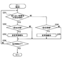
第一実施形態における報知関連処理の流れの一例を示すフローチャート
対象駐車領域の周辺に非定常物が存在しない場合の例を示す模式図
図7と同じ対象駐車領域の周辺に非定常物が存在する場合の例を示す模式図
第一変形例における報知関連処理の流れの一例を示すフローチャート
第二変形例の運転支援ECUの概略的な構成について説明するためのブロック図
ドライバ及び対象駐車領域別の、車両の駐発車方向のパターンと撮像画像との対応関係の一例を示す図
第六変形例の運転支援システムの概略的な構成の一例を示す図
(第一実施形態)
<運転支援システム100の概略構成>
図1は、本開示が適用された運転支援システム100の概略的な構成の一例を示す図である。運転支援システム100は、車両に搭載されるものであり、図1に示すようにカメラ1、車両状態センサ群2、ナビゲーション装置3、表示装置4、音声出力装置5、及び運転支援ECU6を含んでいる。運転支援システム100を搭載している車両を以降ではホスト車あるいはサブジェクトビークルとも呼ぶ。
<運転支援システム100の概略構成>
図1は、本開示が適用された運転支援システム100の概略的な構成の一例を示す図である。運転支援システム100は、車両に搭載されるものであり、図1に示すようにカメラ1、車両状態センサ群2、ナビゲーション装置3、表示装置4、音声出力装置5、及び運転支援ECU6を含んでいる。運転支援システム100を搭載している車両を以降ではホスト車あるいはサブジェクトビークルとも呼ぶ。
カメラ1は、車両に設置されて車両周辺を撮像する。このカメラ1は障害物センサあるいは撮像装置とも言及される。本実施形態では、カメラ1としては、車両前部のコーナー部分が含まれる車両前方所定角範囲を撮像する前方カメラと、車両後部のコーナー部分が含まれる車両後方所定角範囲を撮像する後方カメラとを用いる場合を例に挙げて説明を行う。本実施形態の例では、カメラ1としてステレオカメラを用いる場合を例に挙げて以降の説明を行う。
車両状態センサ群2は、車両の車両状態を検出する各種センサ群である。車両状態センサ群2には、例えば車両の車速を検出する車速センサ、車両のシフトポジションを検出するシフトポジションセンサ、車両の舵角を検出する舵角センサが含まれるものとする。
ナビゲーション装置3は、位置検出器31及び地図DB(データベース)32を備えている。位置検出器31は、例えば、測位衛星からの電波に基づいて車両の現在位置を検出する測位システム等を利用して、車両の現在位置の検出を逐次行う。車両の現在位置は、例えば車両の後輪車軸中心の位置であって、緯度/経度の座標で表すものとする。地図DB32は、ノードデータ及びリンクデータからなる道路データなどを含む地図データを記憶している。リンクとは、電子地図上の各道路を、交差や分岐や合流する点等の複数のノードにて分割したときのノード間を結ぶものである。
表示装置4は、運転支援ECU6の指示に従ってテキストや画像を表示する。例えば表示装置4は、フルカラー表示が可能なものであり、液晶ディスプレイ等を用いて構成することができる。表示装置4としては、インストゥルメントパネル等に設けたディスプレイを用いる構成としてもよいし、HUD(Head-Up Display)を用いる構成としてもよい。音声出力装置5は、スピーカ等から構成され、運転支援ECU6の指示に従って音声を出力する。なお、表示装置4あるいは音声出力装置5は、報知装置とも言及される。
運転支援ECU6は、主にマイクロコンピュータとして構成され、いずれも周知のCPU、ROMやRAM等のメモリ、I/O、及びこれらを接続するバスによって構成される。運転支援ECU6は、カメラ1、車両状態センサ群2、ナビゲーション装置3から入力された各種情報に基づき、各種処理を実行する。この運転支援ECU6は、運転支援装置とも言及される。
なお、運転支援ECU6が実行する機能の一部又は全部を、一つ或いは複数のIC等によりハードウェア的に構成してもよい。
<運転支援ECU6の詳細構成>
図2に示すように、運転支援ECU6は、撮像画像取得部61、対象駐車領域特定部62、駐車領域メモリ63、学習判定部64、パターン特定部65、配置メモリ66、配置記憶部67、支援判定部68、新旧比較部69、障害物特定部70、近接検知部71(検知部とも言及される)、及び報知部72(報知処理部72とも言及される)を備えている。尚、メモリは、記憶器、記憶装置とも言及される。また、記憶部は、記憶処理部とも言及される。
図2に示すように、運転支援ECU6は、撮像画像取得部61、対象駐車領域特定部62、駐車領域メモリ63、学習判定部64、パターン特定部65、配置メモリ66、配置記憶部67、支援判定部68、新旧比較部69、障害物特定部70、近接検知部71(検知部とも言及される)、及び報知部72(報知処理部72とも言及される)を備えている。尚、メモリは、記憶器、記憶装置とも言及される。また、記憶部は、記憶処理部とも言及される。
撮像画像取得部61は、カメラ1で撮像された撮像画像を逐次取得する。対象駐車領域特定部62は、駐車時や発車時に支援を行う対象とする駐車領域(以下、対象駐車領域)を特定し、特定した対象駐車領域の位置を駐車領域メモリ63に記憶する。対象駐車領域の位置は、例えば緯度/経度の座標で表すものとする。
対象駐車領域の特定の一例としては、ナビゲーション装置3においてユーザの自宅として登録されている位置を対象駐車領域と特定する構成とすればよい。また、ユーザが対象駐車領域を設定するための図示しないボタン等を操作したときの車両位置を対象駐車領域と特定する構成としてもよい。他にも、車両が例えば3回等の所定回数以上駐車した位置を対象駐車領域と特定する構成としてもよい。車両が駐車したことは、例えばシフトポジションが駐車位置になったことを車両状態センサ群2で検出したことをもとに運転支援ECU6が判定する構成とすればよい。
なお、対象駐車領域特定部62で自宅の駐車領域と勤務先の駐車領域とを対象駐車領域と特定する場合のように、対象駐車領域を複数特定した場合には、駐車領域メモリ63にはそれら複数の対象駐車領域の位置が記憶されることになる。
学習判定部64、パターン特定部65、配置メモリ66、配置記憶部67、支援判定部68、新旧比較部69、障害物特定部70、近接検知部71、及び報知部72については、後に詳述する。
<第一実施形態における障害物学習処理>
ここで、運転支援ECU6での障害物学習処理について図3のフローチャートを用いて説明を行う。ここで、本開示に記載されるフローチャート、あるいは、フローチャートの処理は、複数のセクション(あるいはステップと言及される)を含み、各セクションは、たとえば、S1と表現される。さらに、各セクションは、複数のサブセクションに分割されることができる、一方、複数のセクションが合わさって一つのセクションにすることも可能である。さらに、各セクションは、デバイス、モジュールとして言及されることができる。また、上記の複数のセクションの各々あるいは組合わさったものは、(i)ハードウエアユニット(例えば、コンピュータ)と組み合わさったソフトウエアのセクションのみならず、(ii)ハードウエア(例えば、集積回路、配線論理回路)のセクションとして、関連する装置の機能を含みあるいは含まずに実現できる。さらに、ハードウエアのセクションは、マイクロコンピュータの内部に含まれることもできる。障害物学習処理は、対象駐車領域周辺の障害物の配置を記憶する処理である。図3のフローチャートは、一例として、車両のイグニッション電源がオンになったときに開始される。
ここで、運転支援ECU6での障害物学習処理について図3のフローチャートを用いて説明を行う。ここで、本開示に記載されるフローチャート、あるいは、フローチャートの処理は、複数のセクション(あるいはステップと言及される)を含み、各セクションは、たとえば、S1と表現される。さらに、各セクションは、複数のサブセクションに分割されることができる、一方、複数のセクションが合わさって一つのセクションにすることも可能である。さらに、各セクションは、デバイス、モジュールとして言及されることができる。また、上記の複数のセクションの各々あるいは組合わさったものは、(i)ハードウエアユニット(例えば、コンピュータ)と組み合わさったソフトウエアのセクションのみならず、(ii)ハードウエア(例えば、集積回路、配線論理回路)のセクションとして、関連する装置の機能を含みあるいは含まずに実現できる。さらに、ハードウエアのセクションは、マイクロコンピュータの内部に含まれることもできる。障害物学習処理は、対象駐車領域周辺の障害物の配置を記憶する処理である。図3のフローチャートは、一例として、車両のイグニッション電源がオンになったときに開始される。
まず、S1では、学習判定部64が、車両が対象駐車領域への駐車及び対象駐車領域からの発車のいずれか(以下、駐発車)を開始したか否かを判定する。一例としては、車両の現在位置と駐車領域メモリ63に記憶されている対象駐車領域の位置との距離が、例えば15m等の所定距離未満であり、車両状態センサ群2で検出している車両のシフトポジションが駐車位置でなく、且つ、車両状態センサ群2で検出している車両の車速が例えば徐行程度の車速以下である場合に、対象駐車領域に車両が駐車を開始したと判定する構成とすればよい。また、車両の現在位置と対象駐車領域の位置とが前述の所定距離未満であり、且つ、車両状態センサ群2で検出している車両のシフトポジションが駐車位置から前進位置や後退位置に移った場合に、対象駐車領域から車両が発車を開始したと判定する構成とすればよい。
他にも、車両状態センサ群2で検出している車両の操舵角が所定値以上変化したことなども条件に加える構成としてもよい。
そして、駐発車を開始したと判定した場合(S1:YES)には、S2に移る。一方、駐発車を開始していないと判定した場合(S1:NO)には、S6に移る。
S2では、パターン特定部65が、車両の状況に応じたパターンを特定する。本実施形態の一例としては、対象駐車領域に対する車両の駐発車方向のパターンを特定する場合を例に挙げて以降の説明を行う。対象駐車領域に対する車両の駐発車方向のパターンは、車両の現在位置と、逐次得られる車両の現在位置から求められる車両の進行方向と、リンクデータと、対象駐車領域とから特定する構成とすればよい。
対象駐車領域に対する車両の駐発車方向のパターンは、図4に示すように、「右方向から後退で進入」、「左方向から後退で進入」、「直進方向から後退で進入」、「右方向から前進で進入」、「左方向から前進で進入」、「直進方向から後退で進入」、「右方向へ後退で退出」、「左方向へ後退で退出」、「直進方向へ後退で退出」、「右方向へ前進で退出」、「左方向へ前進で退出」、「直進方向へ前進で退出」の12パターン存在する。図4は、対象駐車領域別に配置メモリ66に記憶される、対象駐車領域に対する車両の駐発車方向のパターンと撮像画像との対応関係の一例を示す図である。図4では、対象駐車領域Cについての車両の駐発車方向のパターンと撮像画像との対応関係の一例を示している。
S3では、配置記憶部67が、S2で特定したパターンについて、撮像画像が配置メモリ66に記憶済みか否かを判定する。過去の障害物学習処理において、該当するパターンについての撮像画像が記憶されていた場合には、S2で特定したパターンについて、撮像画像が配置メモリ66に記憶済みとなる。一方、障害物学習処理を初めて実行する場合など、該当するパターンについての撮像画像が記憶済みでない場合には、S2で特定したパターンについて、撮像画像が配置メモリ66に記憶済みでないことになる。
S3で記憶済みでないと判定した場合(S3:NO)には、S4に移る。S4では、撮像画像取得部61が撮像画像を取得する。そして、取得した撮像画像を、S2で特定したパターンに対応付けて配置記憶部67が配置メモリ66に記憶し(図4参照)、障害物学習処理を終了する。撮像画像取得部61は、車両の進行方向をカメラ1で撮像した撮像画像を取得するものとする。つまり、前進時には前方カメラの撮像画像を取得し、後退時には後方カメラの撮像画像を取得する。
なお、「右方向から後退で進入」と「右方向から前進で進入」との両パターン、「左方向から後退で進入」と「左方向から前進で進入」との両パターン、「直進方向から後退で進入」と「直進方向から後退で進入」との両パターン、「右方向へ後退で退出」と「右方向へ前進で退出」との両パターン、「左方向へ後退で退出」と「左方向へ前進で退出」との両パターン、及び「直進方向へ後退で退出」と「直進方向へ前進で退出」との両パターンについては、同様の撮像画像が得られると考えられるので、どちらか一方のパターンについての撮像画像が得られた場合には、もう一方のパターンについても共通の撮像画像を記憶する構成としてもよい。
また、S3で記憶済みと判定した場合(S3:YES)には、S5に移る。S5では、配置記憶部67が、S2で特定したパターンに対応付けて配置記憶部67に記憶されている撮像画像を、更新すべきか否か判定する。一例として、障害物学習処理と並行して実行される後述の駐発車支援処理のS27において、撮像画像取得部61が取得した撮像画像から定常的でない非定常物が特定されなかった場合に、更新すべきと判定する構成とすればよい。定常的でない障害物は、非定常障害物あるいは遷移的障害物とも言及される。一方、定常的である障害物は、定常障害物あるいは非遷移障害物とも言及される。
そして、更新すべきと判定した場合(S5:YES)には、S4に移って、撮像画像取得部61が取得した撮像画像を、S2で特定したパターンに対応付けて配置記憶部67が配置メモリ66に上書きで記憶することで、撮像画像を更新する。一方、更新すべきでないと判定した場合(S5:NO)には、S6に移る。
なお、ここでは、撮像画像を更新すべきか否かを判定する構成を示したが、撮像画像を更新すべきか否かを判定せずに常に更新する構成としてもよい。
S6では、障害物学習処理の終了タイミングである場合(S6:YES)には、障害物学習処理を終了する。また、障害物学習処理の終了タイミングでない場合(S6:NO)には、S1に戻って処理を繰り返す。障害物学習処理の終了タイミングの一例としては、車両の現在位置と駐車領域メモリ63に記憶されている対象駐車領域の位置とが、例えば前述の所定距離以上となったときや、車両のイグニッション電源がオフになったときなどがある。
<第一実施形態における駐発車支援処理>
続いて、運転支援ECU6での駐発車支援処理について図5のフローチャートを用いて説明を行う。駐発車支援処理は、対象駐車領域に対しての駐発車時において、車両に近接する障害物を報知する処理である。図5のフローチャートは、一例として、車両のイグニッション電源がオンになったときに開始され、前述の障害物学習処理と並行して実行されるものとする。
続いて、運転支援ECU6での駐発車支援処理について図5のフローチャートを用いて説明を行う。駐発車支援処理は、対象駐車領域に対しての駐発車時において、車両に近接する障害物を報知する処理である。図5のフローチャートは、一例として、車両のイグニッション電源がオンになったときに開始され、前述の障害物学習処理と並行して実行されるものとする。
まず、S21では、前述のS1の処理と同様にして、支援判定部68が、車両が対象駐車領域への駐車及び対象駐車領域からの発車のいずれか(つまり、駐発車)を開始したか否かを判定する。そして、駐発車を開始したと判定した場合(S21:YES)には、S22に移る。一方、駐発車を開始していないと判定した場合(S21:NO)には、S29に移る。
S22では、前述のS2の処理と同様にして、パターン特定部65が、車両の状況に応じたパターンを特定する。本実施形態の例では、対象駐車領域に対する車両の駐発車方向のパターンを特定する。
なお、S21~S22の処理については、駐発車支援処理と並行して実行する障害物学習処理におけるS1~S2の処理を利用する構成としてもよい。この場合、学習判定部64及び支援判定部68のいずれかがもう一方の機能も兼ねる構成とすればよい。
S23では、配置記憶部67が、S21で駐発車を開始したと判定された対象駐車領域とS22で特定したパターンとの組み合わせについて、撮像画像が配置メモリ66に記憶ありか否かを判定する。具体的には、過去の障害物学習処理において、該当するパターンについての撮像画像が記憶されていた場合には、配置メモリ66に記憶ありと判定し、該当するパターンについての撮像画像が記憶されていない場合には、配置メモリ66に記憶なしと判定する。そして、記憶ありと判定した場合(S23:YES)には、S24に移り、記憶なしと判定した場合(S23:NO)には、S29に移る。
S24では、撮像画像取得部61が現在の撮像画像を取得する。よって、撮像画像取得部61は配置取得部とも言及される。S25では、S22で特定したパターンに対応付けて記憶された過去の撮像画像を配置メモリ66から読み出す。S24で取得する現在の撮像画像と、S25で配置メモリ66から読み出す過去の撮像画像とは、撮像した際の対象駐車領域に対する車両の駐発車方向のパターンが同じ撮像画像である。
また、駐発車支援処理と並行して実行している障害物学習処理のS4で配置メモリ66へ撮像画像が記憶される場合であっても、この撮像画像の記憶は、S25以降に行われる後述のS27の処理結果をもとに行われるので、S25では、駐発車支援処理と並行して実行している障害物学習処理よりも過去の障害物学習処理で配置メモリ66に記憶された撮像画像を読み出すことになる。
S26では、新旧比較部69が、S24で取得した現在の撮像画像と、S25で配置メモリ66から読み出した過去の撮像画像とを比較して、撮像画像の差異を検出する。一例としては、公知の経時的差分画像法と同様にして、現在の撮像画像から過去の撮像画像を差し引くことで、撮像画像の差異を検出する構成とすればよい。なお、差異については、誤差程度の範囲以上のものを差異として検出する構成とすればよい。
また、ここで言うところの誤差には、車両の駐発車方向のパターンが同じであっても走行軌跡のずれによって生じる可能性のある撮像画像の差異程度の誤差まで含む構成とすることが好ましい。これによれば、過去の撮像画像が得られた場合の走行軌跡と現在の撮像画像が得られた場合の走行軌跡との間にずれがあったとしても、このずれによる差異を撮像画像の差異と検出せずに済むようになり、後述する非定常物の特定の精度が向上する。
S24で取得した現在の撮像画像と、S25で配置メモリ66から読み出した過去の撮像画像とは、撮像した際の対象駐車領域に対する車両の駐発車方向のパターンが同じ撮像画像であって撮像方向や撮像位置が略同一であるので、定常的な障害物については両撮像画像で配置が一致する筈である。よって、現在の撮像画像から過去の撮像画像を差し引くことで、撮像画像の差異を容易に検出することができる。
なお、現在の撮像画像と過去の撮像画像との間で撮像方向や撮像位置にずれがあることも考慮して、このずれによる影響を取り除いた上で現在の撮像画像から過去の撮像画像を差し引く構成としてもよい。一例としては、現在の撮像画像と過去の撮像画像とで共通な特徴点を複数検出し、その複数の特徴点の位置が重なるように撮像画像に対して拡大縮小や回転等の変形を行うことで、撮像方向や撮像位置のずれによる影響を取り除く構成とすればよい。
S27では、障害物特定部70が、S26で検出した差異をもとに、対象駐車領域周辺における定常的でない障害物(以下、非定常物)や定常的な障害物(以下、定常物)を特定する。
一例としては、公知のステレオ画像処理によってステレオカメラの現在の撮像画像の視差から得られた距離分布(以下、距離画像)と、元画像とから、公知の認識処理によって撮像画像内の複数の立体物や自転車や歩行者や壁等の障害物を検出するとともに、車両と障害物との距離も検出する。そして、検出した障害物のうち、S26で検出した差異の位置に存在するものを非定常物、S26で検出した差異の位置以外に存在するものを定常物と特定する。
また、障害物特定部70は、撮像画像取得部61で逐次取得する撮像画像から得られる距離画像をもとに、車両と定常物や非定常物との距離を逐次検出する。障害物特定部70は、一旦定常物や非定常物を特定した場合には、公知の領域追跡処理によって撮像画像中の定常物や非定常物の位置を追跡することで、再度の定常物や非定常物の特定を行わずに、車両と定常物や非定常物との距離を逐次検出できるようにすればよい。
S28では、報知関連処理を行う。ここで、図6のフローチャートを用いて、報知関連処理の概略について説明を行う。
まず、S281では、近接検知部71が、障害物特定部70で逐次検出される車両と定常物や非定常物との距離から、車両に最も近い障害物が非定常物か否かを判定する。そして、車両に最も近い障害物が非定常物と判定した場合(S281:YES)には、S282に移る。一方、車両に最も近い障害物が非定常物でないと判定した場合(S281:NO)には、S284に移る。一例として、障害物特定部70で非定常物が特定されていない場合や、非定常物が特定されたが車両に最も近い障害物が定常物である場合に、車両に最も近い障害物が非定常物でないと判定される。
なお、車両に最も近い障害物として、車両に接触するまでの距離が最も近い障害物を対象とする構成としてもよい。具体例としては、そのまま進行しても車両に接触しないと予測される障害物は近接したとしても対象とせず、そのまま進行すると車両と接触すると予測される障害物のみを対象とする構成とすればよい。
S282では、車両に最も近いと判定した非定常物と車両との距離が設定距離以下であった場合(S282:YES)には、S283に移る。一方、車両に最も近いと判定した非定常物と車両との距離が設定距離よりも長かった場合(S282:NO)には、S286に移る。ここで言うところの設定距離とは、例えば車両の車速等に応じて任意に設定可能な距離であって、少なくとも障害物との接触を回避するのに必要な距離である。
S283では、報知部72が、表示装置4や音声出力装置5に指示を行って、非定常物(つまり、定常的でない障害物)の存在を示す旨の報知を行う。報知の一例としては、「いつもと異なる位置に障害物があります」等のテキストを表示させたり、音声を出力したり、定常物の存在を示す際の警告音とは異なる種類の警告音を出力させたりするなどの例がある。
なお、非定常物の存在を示す旨の報知は、車両と非定常物との距離が接近するほど警告音の周期を短くするなど、車両と非定常物との距離が接近するのに応じて変化させる構成としてもよい。
また、車両に最も近い障害物が非定常物でないと判定した場合のS284では、車両に最も近いと判定した定常物と車両との距離が設定距離以下であった場合(S284:YES)には、S285に移る。一方、車両に最も近いと判定した定常物と車両との距離が設定距離よりも長かった場合(S284:NO)には、S286に移る。ここで言うところの設定距離は、S282と同一の距離であってもよいし、S282と異なる距離であってもよい。定常物の存在は車両のドライバにとっては認識済みである可能性が高く、あまり近接しないうちから定常物について報知を行うとドライバに煩わしさを感じさせるおそれがあることから、S284における設定距離は、S282における設定距離よりも短くすることが好ましい。
S285では、報知部72が、表示装置4や音声出力装置5に指示を行って、定常物(つまり、定常的な障害物)の存在を示す旨の報知を行う。報知の一例としては、非定常物の存在を示す際の警告音とは異なる種類の警告音を出力させたりするなどの例がある。
なお、定常物の存在は車両のドライバにとっては認識済みである可能性が高いことから、ドライバに煩わしさを感じさせにくくするために、非定常物の存在を示す際の警告音よりも定常物の存在を示す際の警告音の音量を下げるなど、より目立ちにくい構成とすることが好ましい。
S286では、支援判定部68が、車両が駐発車を完了したか否かを判定する。一例として、車両の現在位置と対象駐車領域の位置とが前述の所定距離以上となった場合に、車両が発車を完了したと判定し、車両のシフトポジションが駐車位置となった場合に車両が駐車を完了したと判定する構成とすればよい。そして、駐発車を完了したと判定した場合(S286:YES)には、S29に移る。一方、駐発車を完了していないと判定した場合(S286:NO)には、S281に戻って処理を繰り返す。
図5に戻って、S29では、駐発車支援処理の終了タイミングである場合(S29:YES)には、駐発車支援処理を終了する。また、駐発車支援処理の終了タイミングでない場合(S29:NO)には、S21に戻って処理を繰り返す。駐発車支援処理の終了タイミングの一例としては、車両のイグニッション電源がオフになったときなどがある。
<第一実施形態のまとめ>
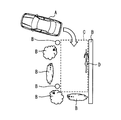
ここで、第一実施形態の構成における作用効果について、具体的に図7、図8を用いて説明を行う。図7は、対象駐車領域の周辺に非定常物が存在しない場合の例を示す模式図であり、図8は、図7と同じ対象駐車領域の周辺に非定常物が存在する場合の例を示す模式図である。図7及び図8のAが車両、Bが定常物、Cが対象駐車領域を示しており、図8のDが非定常物を示している。
ここで、第一実施形態の構成における作用効果について、具体的に図7、図8を用いて説明を行う。図7は、対象駐車領域の周辺に非定常物が存在しない場合の例を示す模式図であり、図8は、図7と同じ対象駐車領域の周辺に非定常物が存在する場合の例を示す模式図である。図7及び図8のAが車両、Bが定常物、Cが対象駐車領域を示しており、図8のDが非定常物を示している。
対象駐車領域周辺に駐発車のたびに常に近接せざるを得ない定常物が存在する場合、第一実施形態の構成によれば、その定常物に近接した際にその定常物の存在を示す報知が行われることになる。ここで、図7に示すように対象駐車領域周辺に非定常物が存在しない状況が続くと、駐発車のたびに毎回似たような報知が行われることになり、定常物の存在を示す報知に対してドライバの慣れが生じ、定常物の存在を示す報知にドライバが注意を払わなくなることがある。
このような状況になったとしても、第一実施形態の構成によれば、図8に示すように対象駐車領域周辺に非定常物が存在する場合には、ドライバにとって慣れの生じていない、定常物の存在を示す報知とは異なった報知を行うので、ドライバが非定常物の存在に気付きやすくなる。
その結果、駐車領域周辺において、駐車や発車のたびに常に近接せざるを得ない定常的な障害物が存在した場合であっても、定常的でない障害物の存在をドライバに気付かせやすくすることが可能になる。
(第一変形例)
前述の実施形態では、定常物に近接した際にその定常物の存在を示す報知を行う構成を示したが、必ずしもこれに限らない。例えば、定常物に近接した際にはその定常物の存在を示す報知を行わず、非定常物に近接した際にだけその非定常物の存在を示す報知を行う構成(以下、第一変形例)としてもよい。以下では、この第一変形例について説明を行う。なお、説明の便宜上、この第一変形例以降の説明において、それまでの実施形態の説明に用いた図に示した部材と同一の機能を有する部材については、同一の符号を付し、その説明を省略する。
前述の実施形態では、定常物に近接した際にその定常物の存在を示す報知を行う構成を示したが、必ずしもこれに限らない。例えば、定常物に近接した際にはその定常物の存在を示す報知を行わず、非定常物に近接した際にだけその非定常物の存在を示す報知を行う構成(以下、第一変形例)としてもよい。以下では、この第一変形例について説明を行う。なお、説明の便宜上、この第一変形例以降の説明において、それまでの実施形態の説明に用いた図に示した部材と同一の機能を有する部材については、同一の符号を付し、その説明を省略する。
第一変形例の運転支援システム100は、駐発車支援処理における報知関連処理が一部異なる点を除けば、第一実施形態の運転支援システム100と同様である。
<第一変形例の報知関連処理>
ここで、図9のフローチャートを用いて、第一変形例における報知関連処理についての説明を行う。
ここで、図9のフローチャートを用いて、第一変形例における報知関連処理についての説明を行う。
まず、S281aでは、前述のS281と同様にして、近接検知部71が、車両に最も近い障害物が非定常物か否かを判定する。そして、車両に最も近い障害物が非定常物と判定した場合(S281a:YES)には、S282aに移る。一方、車両に最も近い障害物が非定常物でないと判定した場合(S281a:NO)には、S284aに移る。S282a~S284aまでの処理は、前述のS282~S283、S286の処理と同様である。
図9のフローチャートによれば、車両に最も近い障害物が定常物と判定された場合には、その定常物についての報知は行わず、車両に最も近い障害物が非定常物と判定された場合にその非定常物についての報知を行うことになる。
<第一変形例のまとめ>
第一変形例の構成によれば、定常物については報知を行わないので、定常物の存在がドライバにとっては認識済みである場合に、定常物の存在を示す報知によってドライバが煩わしさを感じることがなくなる。
第一変形例の構成によれば、定常物については報知を行わないので、定常物の存在がドライバにとっては認識済みである場合に、定常物の存在を示す報知によってドライバが煩わしさを感じることがなくなる。
(第二変形例)
前述の実施形態では、対象駐車領域別に車両の状況に応じたパターンに対応した撮像画像を配置メモリ66に記憶し、対象駐車領域及び車両の状況に応じたパターンに対応した過去の撮像画像を配置メモリ66から読み出す構成を示したが、必ずしもこれに限らない。例えば、ドライバ及び対象駐車領域別に車両の状況に応じたパターンに対応した撮像画像を配置メモリ66に記憶し、ドライバ、対象駐車領域、及び車両の状況に応じたパターンに対応した過去の撮像画像を配置メモリ66から読み出す構成(以下、第二変形例)としてもよい。以下では、この第二変形例について説明を行う。
前述の実施形態では、対象駐車領域別に車両の状況に応じたパターンに対応した撮像画像を配置メモリ66に記憶し、対象駐車領域及び車両の状況に応じたパターンに対応した過去の撮像画像を配置メモリ66から読み出す構成を示したが、必ずしもこれに限らない。例えば、ドライバ及び対象駐車領域別に車両の状況に応じたパターンに対応した撮像画像を配置メモリ66に記憶し、ドライバ、対象駐車領域、及び車両の状況に応じたパターンに対応した過去の撮像画像を配置メモリ66から読み出す構成(以下、第二変形例)としてもよい。以下では、この第二変形例について説明を行う。
第二変形例の運転支援システム100は、運転支援ECU6にドライバを特定するドライバ特定部73をさらに備える点、及び障害物学習処理と駐発車支援処理とが一部異なる点を除けば、第一実施形態の運転支援システム100と同様である。
<第二変形例の運転支援ECU6の詳細構成>
ここで、図10を用いて、第二変形例の運転支援ECU6について説明を行う。図10では、便宜上、運転支援ECU6に備えられる機能ブロックのうち、第二変形例についての説明に必要な機能ブロックのみを記載している。
ここで、図10を用いて、第二変形例の運転支援ECU6について説明を行う。図10では、便宜上、運転支援ECU6に備えられる機能ブロックのうち、第二変形例についての説明に必要な機能ブロックのみを記載している。
第二変形例の運転支援ECU6は、撮像画像取得部61、対象駐車領域特定部62、駐車領域メモリ63、学習判定部64、パターン特定部65、配置メモリ66、配置記憶部67、支援判定部68、新旧比較部69、障害物特定部70、近接検知部71、報知部72、及びドライバ特定部73を備えている。
ドライバ特定部73は、車両を運転中のドライバを特定する。一例としては、車両状態センサ群2として運転席シートの着座部分に設けられた体重計や圧力センサを用い、この体重計で計測される体重やこの圧力センサでの検出値から、個別のドライバを特定する構成とすればよい。他にも、電子キーから受信したIDから個別のドライバを特定する構成などとしてもよい。
<第二変形例における障害物学習処理>
第二変形例における障害物学習処理では、駐発車を開始したと学習判定部64が判定した場合に、パターン特定部65が車両の状況に応じたパターンを特定するのに加え、ドライバ特定部73が車両を運転中のドライバを特定する。
第二変形例における障害物学習処理では、駐発車を開始したと学習判定部64が判定した場合に、パターン特定部65が車両の状況に応じたパターンを特定するのに加え、ドライバ特定部73が車両を運転中のドライバを特定する。
そして、撮像画像取得部61が取得した撮像画像を、パターン特定部65で特定したパターンとドライバ特定部73で特定したドライバとに対応付けて配置記憶部67が配置メモリ66に記憶する。なお、撮像画像の配置メモリ66への記憶は、第一実施形態における障害物学習処理と同様にして、パターン特定部65で特定したパターンとドライバ特定部73で特定したドライバとの組み合わせについて、撮像画像が配置メモリ66に記憶済みでないか、撮像画像の更新が必要と配置記憶部67が判定した場合に行う。
配置メモリ66への撮像画像の記憶は、図11に示すように、ドライバ(図11のX、Y参照)及び駐車領域(図11のC1、C2参照)別に、車両の状況に応じたパターンに対応付けて行われる。図11では、車両の状況に応じたパターンとして、対象駐車領域に対する車両の駐発車方向のパターンを用いた場合を例に示す。
車両を利用するドライバによって対象駐車領域が異なる場合の一例としては、妻は妻の実家の駐車領域が対象駐車領域に該当するが、夫にとっては妻の実家の駐車領域は対象駐車領域に該当しない場合などがある。
<第二変形例における駐発車支援処理>
第二変形例における駐発車支援処理では、駐発車を開始したと支援判定部68が判定した場合に、パターン特定部65でパターン特定部65が車両の状況に応じたパターンを特定するのに加え、ドライバ特定部73が車両を運転中のドライバを特定する。
第二変形例における駐発車支援処理では、駐発車を開始したと支援判定部68が判定した場合に、パターン特定部65でパターン特定部65が車両の状況に応じたパターンを特定するのに加え、ドライバ特定部73が車両を運転中のドライバを特定する。
そして、駐発車を開始したと判定された対象駐車領域とパターン特定部65で特定したパターンとドライバ特定部73で特定したドライバとの組み合わせについて、撮像画像が配置メモリ66に記憶ありと配置記憶部67で判定された場合に、その撮像画像を過去の撮像画像として読み出す。そして、その過去の撮像画像と、撮像画像取得部61が取得する現在の撮像画像とを新旧比較部69が比較して撮像画像の差異を検出する。
<第二変形例のまとめ>
同一の車両を複数のドライバが利用する場合、あるドライバにとっては対象駐車領域となるが、他のドライバにとっては対象駐車領域とならない駐車領域が存在することがある。このような状況であっても、第二変形例によれば、ドライバ別に対象駐車領域の過去の撮像画像を記憶するので、ドライバごとの対象駐車領域に応じた駐発車の支援を受けることが可能になる。
同一の車両を複数のドライバが利用する場合、あるドライバにとっては対象駐車領域となるが、他のドライバにとっては対象駐車領域とならない駐車領域が存在することがある。このような状況であっても、第二変形例によれば、ドライバ別に対象駐車領域の過去の撮像画像を記憶するので、ドライバごとの対象駐車領域に応じた駐発車の支援を受けることが可能になる。
(第三変形例)
前述の実施形態では、車両の状況に応じたパターンとして、対象駐車領域に対する車両の駐発車方向のパターンを一例として示したが、必ずしもこれに限らない。車両の状況に応じたパターンとしては、時間帯や天候のパターンを用いる構成(以下、第三変形例)としてもよい。
前述の実施形態では、車両の状況に応じたパターンとして、対象駐車領域に対する車両の駐発車方向のパターンを一例として示したが、必ずしもこれに限らない。車両の状況に応じたパターンとしては、時間帯や天候のパターンを用いる構成(以下、第三変形例)としてもよい。
時間帯や天候のパターンとしては、昼か夜かといったパターン分けや晴天か曇天か雨天か雪かといったパターン分けなど、同一の障害物が画像認識上で同一と認識できなくなる程度の変化がある区分でパターン分けを行う構成とすればよい。
第三変形例の構成によれば、時間帯や天候といった条件が同じ現在と過去との撮像画像から非定常物の特定を行うことが可能になるので、時間帯や天候といった条件が異なる場合に生じる誤判定の影響を排除して、非定常物の特定をより精度良く行うことが可能になる。
(第四変形例)
また、車両の状況に応じたパターンとして、対象駐車領域までの車両の距離も用いる構成としてもよい。対象駐車領域までの車両の距離のパターンとしては、例えば数段階程度にパターン分けする構成(以下、第四変形例)とすればよい。
また、車両の状況に応じたパターンとして、対象駐車領域までの車両の距離も用いる構成としてもよい。対象駐車領域までの車両の距離のパターンとしては、例えば数段階程度にパターン分けする構成(以下、第四変形例)とすればよい。
対象駐車領域までの車両の距離が大幅に異なると、現在と過去とで実際に存在する障害物の数は同じであっても、現在の撮像画像と過去の撮像画像とで映りこむ障害物の数が異なってしまい、非定常物の特定の精度が低下する場合がある。
これに対して第四変形例の構成によれば、対象駐車領域までの車両の距離という条件が同じ現在と過去との撮像画像から非定常物の特定を行うことが可能になるので、対象駐車領域までの車両の距離が大幅に異なる場合に生じる誤判定の影響を排除して、非定常物の特定をより精度良く行うことが可能になる。
(第五変形例)
前述の実施形態では、カメラ1として前方カメラと後方カメラとの両方を用いる構成を示したが、必ずしもこれに限らない。例えば、カメラ1として、前方カメラ及び後方カメラのうち前方カメラのみを用いる構成としてもよいし、後方カメラのみを用いる構成としてもよい。
前述の実施形態では、カメラ1として前方カメラと後方カメラとの両方を用いる構成を示したが、必ずしもこれに限らない。例えば、カメラ1として、前方カメラ及び後方カメラのうち前方カメラのみを用いる構成としてもよいし、後方カメラのみを用いる構成としてもよい。
例えば、前方カメラのみを用いる構成とした場合には、対象駐車領域から前進で発進する場合や対象駐車領域に前進で進入する場合にのみ本開示を適用すればよいし、後方カメラのみを用いる構成とした場合には、対象駐車領域から後退で発進する場合や対象駐車領域に後退で進入する場合にのみ本開示を適用すればよい。
(第六変形例)
前述の実施形態では、障害物の配置を記憶して比較するためのセンサとしての機能と、障害物までの距離を検出するためのセンサとしての機能との両方をカメラ1が担う構成を示したが、必ずしもこれに限らない。例えば、障害物の配置を記憶して比較するためのセンサと、障害物までの距離を検出するためのセンサとで異なる種類の他のセンサを用いる構成(以下、第六変形例)としてもよい。以下では、障害物の配置を記憶して比較するためのセンサとしてはカメラ1を用い、障害物までの距離を検出するための他のセンサとしては超音波センサ7を用いる場合を例に挙げて、第六変形例についての説明を行う。
前述の実施形態では、障害物の配置を記憶して比較するためのセンサとしての機能と、障害物までの距離を検出するためのセンサとしての機能との両方をカメラ1が担う構成を示したが、必ずしもこれに限らない。例えば、障害物の配置を記憶して比較するためのセンサと、障害物までの距離を検出するためのセンサとで異なる種類の他のセンサを用いる構成(以下、第六変形例)としてもよい。以下では、障害物の配置を記憶して比較するためのセンサとしてはカメラ1を用い、障害物までの距離を検出するための他のセンサとしては超音波センサ7を用いる場合を例に挙げて、第六変形例についての説明を行う。
第六変形例の運転支援システム100aは、超音波センサ7を含む点、及び運転支援ECU6での駐発車支援処理が一部異なる点を除けば、第一実施形態の運転支援システム100と同様である。
<運転支援システム100aの概略構成>
運転支援システム100aは、車両に搭載されるものであり、図12に示すようにカメラ1、車両状態センサ群2、ナビゲーション装置3、表示装置4、音声出力装置5、運転支援ECU6、及び超音波センサ7を含んでいる。
運転支援システム100aは、車両に搭載されるものであり、図12に示すようにカメラ1、車両状態センサ群2、ナビゲーション装置3、表示装置4、音声出力装置5、運転支援ECU6、及び超音波センサ7を含んでいる。
超音波センサ7は、車両に設置されて車両周辺の障害物までの距離を検出する。この超音波センサ7は障害物センサとも言及される。ここでは、超音波センサ7としては、車両前部のコーナー部分が含まれる車両前方所定角範囲が走査範囲となるように車両の前部に複数設けられた超音波センサ7と、車両後部のコーナー部分が含まれる車両後方所定角範囲が走査範囲となるように車両の後部に複数設けられた超音波センサ7とを用いる場合を例に挙げて説明を行う。
なお、ここでは、超音波センサ7を用いる構成を例に挙げて説明を行うが、探査波の送受波の遅延時間によって車両から障害物までの距離を検出するセンサであれば、レーダなどの超音波センサ以外のセンサを用いる構成としてもよい。
また、第六変形例の運転支援ECU6は、複数の超音波センサ7で検出した障害物までの距離から三角測量によって車両に対する障害物の位置を検出する構成とすればよい。なお、超音波センサ7の代わりにレーダを用いる場合には、位相モノパルス方式のレーダを用いることで、探査波の送受波の位相差から求まる車両に対する障害物の方位と、探査波の送受波の遅延時間から求まる距離とから、車両に対する障害物の位置を検出する構成とすればよい。
<第六変形例における駐発車支援処理>
第六変形例における駐発車支援処理は、対象駐車領域周辺における非定常物や定常物を特定する処理が異なる点を除けば、第一実施形態における駐発車支援処理と同様である。
第六変形例における駐発車支援処理は、対象駐車領域周辺における非定常物や定常物を特定する処理が異なる点を除けば、第一実施形態における駐発車支援処理と同様である。
第六変形例における駐発車支援処理では、超音波センサ7で検出した障害物のうち、第一実施形態のS26と同様の処理で検出した差異の位置に存在するものを非定常物、その差異の位置以外に存在するものを定常物と特定する。なお、超音波センサ7で検出した障害物の位置と、第一実施形態のS26と同様の処理で検出した差異の位置(つまり、距離画像中の位置)との対応付けは、両者とも車両に対する相対位置であることを利用して行う構成とすればよい。
そして、第六変形例の障害物特定部70は、超音波センサ7で車両と定常物や非定常物との距離を逐次検出し、前述の報知関連処理を実行する。
<第六変形例のまとめ>
第六変形例の構成によっても、第一実施形態と同様に、駐車領域周辺において、駐車や発車のたびに常に近接せざるを得ない定常的な障害物が存在した場合であっても、定常的でない障害物の存在をドライバに気付かせやすくすることが可能になる。
第六変形例の構成によっても、第一実施形態と同様に、駐車領域周辺において、駐車や発車のたびに常に近接せざるを得ない定常的な障害物が存在した場合であっても、定常的でない障害物の存在をドライバに気付かせやすくすることが可能になる。
(第七変形例)
また、カメラ1の代わりに、探査波の送受波によって車両に対する障害物の位置を検出する超音波センサやレーダなどのセンサを用いる構成(以下、第七変形例)としてもよい。超音波センサやレーダなどのセンサを用いる場合は、障害物の配置として撮像画像を用いる代わりに、超音波センサやレーダなどで検出した障害物の位置の分布を用いる構成とすればよい。
また、カメラ1の代わりに、探査波の送受波によって車両に対する障害物の位置を検出する超音波センサやレーダなどのセンサを用いる構成(以下、第七変形例)としてもよい。超音波センサやレーダなどのセンサを用いる場合は、障害物の配置として撮像画像を用いる代わりに、超音波センサやレーダなどで検出した障害物の位置の分布を用いる構成とすればよい。
第七変形例の構成によっても、第一実施形態と同様に、駐車領域周辺において、駐車や発車のたびに常に近接せざるを得ない定常的な障害物が存在した場合であっても、定常的でない障害物の存在をドライバに気付かせやすくすることが可能になる。
(第八変形例)
他にも、車両の前部では超音波センサ7を用い、車両の後部ではカメラ1を用いるなどといったように、車両の前部と後部とで用いるセンサの種類を異ならせる構成としてもよい。
他にも、車両の前部では超音波センサ7を用い、車両の後部ではカメラ1を用いるなどといったように、車両の前部と後部とで用いるセンサの種類を異ならせる構成としてもよい。
(第九変形例)
前述の実施形態では、障害物特定部70で特定した非定常物と車両との距離が設定距離以下となった場合に、報知部72が非定常物の存在を示す旨の報知を行う構成を示したが、必ずしもこれに限らない。例えば、障害物特定部70で非定常物を特定した場合に、車両と非定常物との距離に関わらず、報知部72が非定常物の存在を示す旨の報知を行う構成としてもよい。
前述の実施形態では、障害物特定部70で特定した非定常物と車両との距離が設定距離以下となった場合に、報知部72が非定常物の存在を示す旨の報知を行う構成を示したが、必ずしもこれに限らない。例えば、障害物特定部70で非定常物を特定した場合に、車両と非定常物との距離に関わらず、報知部72が非定常物の存在を示す旨の報知を行う構成としてもよい。
(第十変形例)
前述の実施形態では、ナビゲーション装置3に備えられる位置検出器31及び地図DB32を用いる構成を示したが、必ずしもこれに限らない。例えば、ナビゲーション装置3に備えられる位置検出器31及び地図DB32を用いずに、公知のロケータに備えられる位置検出器を用いたり、サーバに備えられた地図DBを用いたりする構成としてもよい。
前述の実施形態では、ナビゲーション装置3に備えられる位置検出器31及び地図DB32を用いる構成を示したが、必ずしもこれに限らない。例えば、ナビゲーション装置3に備えられる位置検出器31及び地図DB32を用いずに、公知のロケータに備えられる位置検出器を用いたり、サーバに備えられた地図DBを用いたりする構成としてもよい。
本開示は、実施例に準拠して記述されたが、本開示は当該実施例や構造に限定されるものではないと理解される。本開示は、様々な変形例や均等範囲内の変形をも包含する。加えて、様々な組み合わせや形態、さらには、それらに一要素のみ、それ以上、あるいはそれ以下、を含む他の組み合わせや形態をも、本開示の範疇や思想範囲に入るものである。
Claims (10)
- 車両で用いられ、
前記車両のドライバに向けて報知を行う報知部(72)と、
対象とする駐車領域周辺の過去の障害物の配置を記憶している配置メモリ(66)と、
前記車両を前記駐車領域に進入させる運転時、及び前記駐車領域から発車させる運転時の少なくともいずれかである駐車領域周辺運転時に、前記駐車領域周辺の現在の障害物の配置を取得する配置取得部(61)と、
前記配置メモリに記憶されている過去の障害物の配置と、前記配置取得部で取得した現在の障害物の配置との差異をもとに、前記駐車領域周辺における定常的でない障害物である非定常障害物を特定する障害物特定部(70)とを備え、
前記報知部は、前記障害物特定部で特定した非定常障害物の存在を示す旨の報知を行う
運転支援装置。 - 請求項1において、
前記車両の周辺に存在する障害物を検出する障害物センサ(1、7)を用いて、前記車両に近接する障害物を検知する検知部(71)を備え、
前記報知部は、非定常障害物を前記障害物特定部で特定した場合であって、且つ、その非定常障害物を前記検知部で検知した場合に、非定常障害物の存在を示す旨の前記報知を行う
運転支援装置。 - 請求項2において、
前記障害物特定部は、非定常障害物に加え、定常的な障害物である定常障害物も特定するものであって、
前記報知部は、定常障害物を前記障害物特定部で特定した場合であって、且つ、その定常障害物を前記検知部で検知した場合、非定常障害物の存在を示す旨の前記報知と区別できる態様の報知を行う
運転支援装置。 - 請求項2において、
前記報知部は、前記障害物特定部で特定した非定常障害物以外の障害物については報知を行わない
運転支援装置。 - 請求項2~4のいずれか1項において、
前記検知部で用いる前記障害物センサによって、前記配置メモリに記憶している過去の障害物の配置、及び前記配置取得部で取得する現在の障害物の配置を得る
運転支援装置。 - 請求項2~4のいずれか1項において、
前記検知部で用いる前記障害物センサとは異なる、前記車両の周辺に存在する障害物を検出する他の障害物センサによって、前記配置メモリに記憶している過去の障害物の配置、及び前記配置取得部で取得する現在の障害物の配置を得る
運転支援装置。 - 請求項5又は6において、
前記配置メモリに記憶している過去の障害物の配置、及び前記配置取得部で取得する現在の障害物の配置を得る前記障害物センサは、撮像装置であって、
前記配置メモリは、前記駐車領域周辺を前記撮像装置で撮像した画像を、前記駐車領域周辺の過去の障害物の配置として記憶しておき、
前記配置取得部は、前記駐車領域周辺運転時に前記撮像装置で撮像した画像を、前記駐車領域周辺の現在の障害物の配置として取得する
運転支援装置。 - 請求項1~7のいずれか1項において、
前記配置メモリは、前記駐車領域周辺運転時の状況に応じて類別されたパターン別に過去の障害物の配置を記憶しており、
前記駐車領域周辺運転時に、その駐車領域周辺運転時の状況に応じた前記パターンを特定するパターン特定部(65)を備え、
前記障害物特定部は、前記配置メモリに記憶されている過去の障害物の配置のうち、前記パターン特定部で特定した前記パターンに応じた過去の障害物の配置と、前記配置取得部で取得した現在の障害物の配置との差異をもとに、前記駐車領域周辺における非定常障害物を特定する
運転支援装置。 - 請求項8において、
前記パターンは、前記駐車領域に対する前記車両の方向、前記駐車領域までの前記車両の距離、時間帯、及び天候の少なくともいずれかである
運転支援装置。 - 請求項1~9のいずれか1項において、
前記配置メモリは、前記車両を利用するドライバが複数存在する場合に、そのドライバ別に、対象とする前記駐車領域周辺の過去の障害物の配置を記憶しており、
前記車両を運転中のドライバを特定するドライバ特定部(73)を備え、
前記障害物特定部は、前記配置メモリに記憶されている過去の障害物の配置のうち、前記ドライバ特定部で特定したドライバに応じた過去の障害物の配置と、前記配置取得部で取得した現在の障害物の配置との差異をもとに、前記駐車領域周辺における非定常的障害物を特定する
運転支援装置。
Priority Applications (3)
| Application Number | Priority Date | Filing Date | Title |
|---|---|---|---|
| US15/310,882 US9830826B2 (en) | 2014-06-10 | 2015-05-26 | Driving assistance apparatus |
| CN201580030390.XA CN106458126B (zh) | 2014-06-10 | 2015-05-26 | 驾驶辅助装置 |
| DE112015002772.6T DE112015002772T5 (de) | 2014-06-10 | 2015-05-26 | Fahrunterstützungsvorrichtung |
Applications Claiming Priority (2)
| Application Number | Priority Date | Filing Date | Title |
|---|---|---|---|
| JP2014-119944 | 2014-06-10 | ||
| JP2014119944A JP2015231818A (ja) | 2014-06-10 | 2014-06-10 | 運転支援装置 |
Publications (1)
| Publication Number | Publication Date |
|---|---|
| WO2015190050A1 true WO2015190050A1 (ja) | 2015-12-17 |
Family
ID=54833168
Family Applications (1)
| Application Number | Title | Priority Date | Filing Date |
|---|---|---|---|
| PCT/JP2015/002659 Ceased WO2015190050A1 (ja) | 2014-06-10 | 2015-05-26 | 運転支援装置 |
Country Status (5)
| Country | Link |
|---|---|
| US (1) | US9830826B2 (ja) |
| JP (1) | JP2015231818A (ja) |
| CN (1) | CN106458126B (ja) |
| DE (1) | DE112015002772T5 (ja) |
| WO (1) | WO2015190050A1 (ja) |
Cited By (1)
| Publication number | Priority date | Publication date | Assignee | Title |
|---|---|---|---|---|
| WO2019167519A1 (ja) * | 2018-02-27 | 2019-09-06 | 日立オートモティブシステムズ株式会社 | ノイズキャンセル学習装置、及び、それを備えた車両 |
Families Citing this family (10)
| Publication number | Priority date | Publication date | Assignee | Title |
|---|---|---|---|---|
| JP6761708B2 (ja) * | 2016-09-05 | 2020-09-30 | パナソニック インテレクチュアル プロパティ コーポレーション オブ アメリカPanasonic Intellectual Property Corporation of America | 駐車位置特定方法、駐車位置学習方法、駐車位置特定システム、駐車位置学習装置およびプログラム |
| DE112017008042T5 (de) * | 2017-09-15 | 2020-07-09 | Mitsubishi Electric Corporation | Fahrassistenzvorrichtung und Fahrassistenzverfahren |
| JP6980897B2 (ja) | 2018-03-12 | 2021-12-15 | 日立Astemo株式会社 | 車両制御装置 |
| JP7187169B2 (ja) | 2018-04-23 | 2022-12-12 | フォルシアクラリオン・エレクトロニクス株式会社 | 情報処理装置及び情報処理方法 |
| US20200058223A1 (en) * | 2018-07-31 | 2020-02-20 | Nikos Perivolaris | Object filtering motion detection system |
| JP7347406B2 (ja) * | 2020-11-30 | 2023-09-20 | トヨタ自動車株式会社 | 画像表示装置、プログラム及び画像表示方法 |
| MX2024006342A (es) * | 2021-11-30 | 2024-06-11 | Nissan Motor | Metodo de asistencia al estacionamiento y dispositivo de asistencia al estacionamiento. |
| EP4442522A4 (en) * | 2021-11-30 | 2025-05-07 | Nissan Motor Co., Ltd. | PARKING ASSISTANCE METHOD AND PARKING ASSISTANCE DEVICE |
| JP2023167136A (ja) * | 2022-05-11 | 2023-11-24 | 日立Astemo株式会社 | 運転支援装置 |
| CN118323179A (zh) * | 2024-03-27 | 2024-07-12 | 北京易控智驾科技有限公司 | 车辆控制方法及装置、存储介质及电子设备 |
Citations (6)
| Publication number | Priority date | Publication date | Assignee | Title |
|---|---|---|---|---|
| JPH07291063A (ja) * | 1994-04-22 | 1995-11-07 | Nippondenso Co Ltd | 停止物距離警報装置 |
| JP2001357498A (ja) * | 2000-06-15 | 2001-12-26 | Mazda Motor Corp | 車両用情報提供装置 |
| JP2005008020A (ja) * | 2003-06-18 | 2005-01-13 | Denso Corp | 車両用走行情報報知装置 |
| JP2007243464A (ja) * | 2006-03-07 | 2007-09-20 | Aisin Aw Co Ltd | 駐車支援方法及び駐車支援装置 |
| WO2009090695A1 (ja) * | 2008-01-16 | 2009-07-23 | Mitsubishi Electric Corporation | 車両用センサシステム |
| JP2011126337A (ja) * | 2009-12-15 | 2011-06-30 | Toyota Motor Corp | 運転支援装置 |
Family Cites Families (3)
| Publication number | Priority date | Publication date | Assignee | Title |
|---|---|---|---|---|
| DE19514654B4 (de) | 1994-04-20 | 2009-07-09 | Denso Corporation, Kariya | Kollisionsalarmsystem für ein Kraftfahrzeug |
| JP2008227646A (ja) * | 2007-03-09 | 2008-09-25 | Clarion Co Ltd | 障害物検知装置 |
| US9069356B2 (en) * | 2011-06-12 | 2015-06-30 | Microsoft Technology Licensing, Llc | Nomadic security device with patrol alerts |
-
2014
- 2014-06-10 JP JP2014119944A patent/JP2015231818A/ja active Pending
-
2015
- 2015-05-26 WO PCT/JP2015/002659 patent/WO2015190050A1/ja not_active Ceased
- 2015-05-26 DE DE112015002772.6T patent/DE112015002772T5/de not_active Withdrawn
- 2015-05-26 CN CN201580030390.XA patent/CN106458126B/zh not_active Expired - Fee Related
- 2015-05-26 US US15/310,882 patent/US9830826B2/en not_active Expired - Fee Related
Patent Citations (6)
| Publication number | Priority date | Publication date | Assignee | Title |
|---|---|---|---|---|
| JPH07291063A (ja) * | 1994-04-22 | 1995-11-07 | Nippondenso Co Ltd | 停止物距離警報装置 |
| JP2001357498A (ja) * | 2000-06-15 | 2001-12-26 | Mazda Motor Corp | 車両用情報提供装置 |
| JP2005008020A (ja) * | 2003-06-18 | 2005-01-13 | Denso Corp | 車両用走行情報報知装置 |
| JP2007243464A (ja) * | 2006-03-07 | 2007-09-20 | Aisin Aw Co Ltd | 駐車支援方法及び駐車支援装置 |
| WO2009090695A1 (ja) * | 2008-01-16 | 2009-07-23 | Mitsubishi Electric Corporation | 車両用センサシステム |
| JP2011126337A (ja) * | 2009-12-15 | 2011-06-30 | Toyota Motor Corp | 運転支援装置 |
Cited By (3)
| Publication number | Priority date | Publication date | Assignee | Title |
|---|---|---|---|---|
| WO2019167519A1 (ja) * | 2018-02-27 | 2019-09-06 | 日立オートモティブシステムズ株式会社 | ノイズキャンセル学習装置、及び、それを備えた車両 |
| JPWO2019167519A1 (ja) * | 2018-02-27 | 2021-01-14 | 日立オートモティブシステムズ株式会社 | ノイズキャンセル学習装置、及び、それを備えた車両 |
| US11429108B2 (en) | 2018-02-27 | 2022-08-30 | Hitachi Astemo, Ltd. | Noise-cancelling learning device and vehicle provided with same |
Also Published As
| Publication number | Publication date |
|---|---|
| US9830826B2 (en) | 2017-11-28 |
| US20170076608A1 (en) | 2017-03-16 |
| CN106458126B (zh) | 2019-04-02 |
| JP2015231818A (ja) | 2015-12-24 |
| CN106458126A (zh) | 2017-02-22 |
| DE112015002772T5 (de) | 2017-03-02 |
Similar Documents
| Publication | Publication Date | Title |
|---|---|---|
| JP6260462B2 (ja) | 運転支援装置 | |
| WO2015190050A1 (ja) | 運転支援装置 | |
| EP3800111B1 (en) | Periphery monitoring device | |
| JP6303453B2 (ja) | 駐車支援装置 | |
| JP6917330B2 (ja) | 駐車支援装置 | |
| CN114555420B (zh) | 车辆用周边监视装置以及车辆用周边监视方法 | |
| KR102513745B1 (ko) | 운전 지원 장치 | |
| WO2016063535A1 (ja) | 障害物警報装置 | |
| WO2019239747A1 (ja) | 車両制御装置 | |
| US10347126B2 (en) | Driving assistance device | |
| CN114502428B (zh) | 车辆用驾驶辅助装置以及车辆用驾驶辅助方法 | |
| WO2017104209A1 (ja) | 運転支援装置 | |
| JP2022502642A (ja) | 移動手段周辺の物体が移動手段の運転操作に及ぼす影響を評価する方法 | |
| WO2015136863A1 (ja) | 駐車支援装置 | |
| JP2004221871A (ja) | 車輌周辺監視装置 | |
| JP6552285B2 (ja) | 車載表示装置及び車両後方映像表示方法 | |
| JP5287464B2 (ja) | 運転支援システム | |
| US20230182722A1 (en) | Collision avoidance method and apparatus | |
| JP7495573B2 (ja) | 通知システム、サーバ、携帯装置、及び鞍乗り型車両 | |
| JP7618350B2 (ja) | 制御装置、警告制御方法およびプログラム | |
| US20260070574A1 (en) | Driving assistance device | |
| JP5831269B2 (ja) | 運転支援装置 | |
| WO2023026760A1 (ja) | 物体検知装置、物体検知方法 | |
| JP2025073569A (ja) | 注意喚起装置および注意喚起方法 | |
| JP2024143116A (ja) | 運転支援装置、運転支援方法及びコンピュータプログラム |
Legal Events
| Date | Code | Title | Description |
|---|---|---|---|
| 121 | Ep: the epo has been informed by wipo that ep was designated in this application |
Ref document number: 15807512 Country of ref document: EP Kind code of ref document: A1 |
|
| WWE | Wipo information: entry into national phase |
Ref document number: 15310882 Country of ref document: US |
|
| WWE | Wipo information: entry into national phase |
Ref document number: 112015002772 Country of ref document: DE |
|
| 122 | Ep: pct application non-entry in european phase |
Ref document number: 15807512 Country of ref document: EP Kind code of ref document: A1 |