WO2015186768A1 - 内燃機関およびこれを備えた船舶 - Google Patents
内燃機関およびこれを備えた船舶 Download PDFInfo
- Publication number
- WO2015186768A1 WO2015186768A1 PCT/JP2015/066120 JP2015066120W WO2015186768A1 WO 2015186768 A1 WO2015186768 A1 WO 2015186768A1 JP 2015066120 W JP2015066120 W JP 2015066120W WO 2015186768 A1 WO2015186768 A1 WO 2015186768A1
- Authority
- WO
- WIPO (PCT)
- Prior art keywords
- fuel gas
- gas
- fuel
- valve
- premixed
- Prior art date
- Legal status (The legal status is an assumption and is not a legal conclusion. Google has not performed a legal analysis and makes no representation as to the accuracy of the status listed.)
- Ceased
Links
Images








Classifications
-
- F—MECHANICAL ENGINEERING; LIGHTING; HEATING; WEAPONS; BLASTING
- F02—COMBUSTION ENGINES; HOT-GAS OR COMBUSTION-PRODUCT ENGINE PLANTS
- F02B—INTERNAL-COMBUSTION PISTON ENGINES; COMBUSTION ENGINES IN GENERAL
- F02B25/00—Engines characterised by using fresh charge for scavenging cylinders
- F02B25/02—Engines characterised by using fresh charge for scavenging cylinders using unidirectional scavenging
- F02B25/04—Engines having ports both in cylinder head and in cylinder wall near bottom of piston stroke
-
- F—MECHANICAL ENGINEERING; LIGHTING; HEATING; WEAPONS; BLASTING
- F02—COMBUSTION ENGINES; HOT-GAS OR COMBUSTION-PRODUCT ENGINE PLANTS
- F02B—INTERNAL-COMBUSTION PISTON ENGINES; COMBUSTION ENGINES IN GENERAL
- F02B43/00—Engines characterised by operating on gaseous fuels; Plants including such engines
-
- F—MECHANICAL ENGINEERING; LIGHTING; HEATING; WEAPONS; BLASTING
- F02—COMBUSTION ENGINES; HOT-GAS OR COMBUSTION-PRODUCT ENGINE PLANTS
- F02D—CONTROLLING COMBUSTION ENGINES
- F02D19/00—Controlling engines characterised by their use of non-liquid fuels, pluralities of fuels, or non-fuel substances added to the combustible mixtures
- F02D19/06—Controlling engines characterised by their use of non-liquid fuels, pluralities of fuels, or non-fuel substances added to the combustible mixtures peculiar to engines working with pluralities of fuels, e.g. alternatively with light and heavy fuel oil, other than engines indifferent to the fuel consumed
- F02D19/08—Controlling engines characterised by their use of non-liquid fuels, pluralities of fuels, or non-fuel substances added to the combustible mixtures peculiar to engines working with pluralities of fuels, e.g. alternatively with light and heavy fuel oil, other than engines indifferent to the fuel consumed simultaneously using pluralities of fuels
- F02D19/10—Controlling engines characterised by their use of non-liquid fuels, pluralities of fuels, or non-fuel substances added to the combustible mixtures peculiar to engines working with pluralities of fuels, e.g. alternatively with light and heavy fuel oil, other than engines indifferent to the fuel consumed simultaneously using pluralities of fuels peculiar to compression-ignition engines in which the main fuel is gaseous
-
- F—MECHANICAL ENGINEERING; LIGHTING; HEATING; WEAPONS; BLASTING
- F02—COMBUSTION ENGINES; HOT-GAS OR COMBUSTION-PRODUCT ENGINE PLANTS
- F02D—CONTROLLING COMBUSTION ENGINES
- F02D41/00—Electrical control of supply of combustible mixture or its constituents
- F02D41/02—Circuit arrangements for generating control signals
- F02D41/04—Introducing corrections for particular operating conditions
-
- F—MECHANICAL ENGINEERING; LIGHTING; HEATING; WEAPONS; BLASTING
- F02—COMBUSTION ENGINES; HOT-GAS OR COMBUSTION-PRODUCT ENGINE PLANTS
- F02M—SUPPLYING COMBUSTION ENGINES IN GENERAL WITH COMBUSTIBLE MIXTURES OR CONSTITUENTS THEREOF
- F02M21/00—Apparatus for supplying engines with non-liquid fuels, e.g. gaseous fuels stored in liquid form
- F02M21/02—Apparatus for supplying engines with non-liquid fuels, e.g. gaseous fuels stored in liquid form for gaseous fuels
-
- Y—GENERAL TAGGING OF NEW TECHNOLOGICAL DEVELOPMENTS; GENERAL TAGGING OF CROSS-SECTIONAL TECHNOLOGIES SPANNING OVER SEVERAL SECTIONS OF THE IPC; TECHNICAL SUBJECTS COVERED BY FORMER USPC CROSS-REFERENCE ART COLLECTIONS [XRACs] AND DIGESTS
- Y02—TECHNOLOGIES OR APPLICATIONS FOR MITIGATION OR ADAPTATION AGAINST CLIMATE CHANGE
- Y02T—CLIMATE CHANGE MITIGATION TECHNOLOGIES RELATED TO TRANSPORTATION
- Y02T10/00—Road transport of goods or passengers
- Y02T10/10—Internal combustion engine [ICE] based vehicles
- Y02T10/12—Improving ICE efficiencies
-
- Y—GENERAL TAGGING OF NEW TECHNOLOGICAL DEVELOPMENTS; GENERAL TAGGING OF CROSS-SECTIONAL TECHNOLOGIES SPANNING OVER SEVERAL SECTIONS OF THE IPC; TECHNICAL SUBJECTS COVERED BY FORMER USPC CROSS-REFERENCE ART COLLECTIONS [XRACs] AND DIGESTS
- Y02—TECHNOLOGIES OR APPLICATIONS FOR MITIGATION OR ADAPTATION AGAINST CLIMATE CHANGE
- Y02T—CLIMATE CHANGE MITIGATION TECHNOLOGIES RELATED TO TRANSPORTATION
- Y02T10/00—Road transport of goods or passengers
- Y02T10/10—Internal combustion engine [ICE] based vehicles
- Y02T10/30—Use of alternative fuels, e.g. biofuels
Definitions
- the present invention relates to an internal combustion engine that performs premixed combustion using fuel gas, and a ship equipped with the same.
- a dual fuel engine (hereinafter referred to as "DF engine") has been developed as a marine main engine in anticipation of demand for liquefied gas carriers such as LNG (liquefied natural gas) (see Patent Documents 1 and 2 below).
- the DF engine is provided with a fuel oil mode for burning fuel oil and a fuel gas mode for burning fuel gas such as LNG.
- fuel oil is generally used as a pilot fuel for ignition.
- Patent No. 5395848 gazette International Publication No. 2013/183737
- a DF engine used as a marine main vessel of a liquefied gas carrier a low-speed two-stroke diesel engine whose rotation speed at rating is 200 rpm or less is used.
- a diffusion combustion type in which diffusion combustion of fuel gas is performed when performing a fuel gas mode
- a premix combustion type in which premix combustion of fuel gas is performed.
- FIG. 12 shows a diffusion combustion type DF engine.
- the diffusion combustion type DF engine 100 includes a cylinder liner 101 and a piston 103 that reciprocates in the cylinder liner 101.
- a cylinder cover 105 is provided at the upper end of the cylinder liner 101.
- the cylinder cover 105 is provided with one exhaust valve 107, two diffusion fuel gas injection valves 109, and two fuel oil valves 111. It is done. Further, a scavenging port 113 is provided below the cylinder liner 103.
- Such diffusion combustion with fuel gas has the advantage of having the same level of combustion stability as diffusion combustion with fuel oil of a diesel engine.
- diesel engines using diffusion combustion with fuel gas can reduce NOx (nitrogen oxide) by about 20 to 30% compared to diesel engines using diffusion combustion with fuel oil, but diffusion combustion is used As a result, NOx emissions are still high, and it is not possible to satisfy Tier III defined by the International Maritime Organization (IMO), especially when used as a marine main engine. Therefore, in the emission control area (ECA; emission control area) to which the above-mentioned Tier III is applied, there is a problem that it can not be operated unless some measures for NOx emission reduction are taken.
- ECA emission control area
- exhaust gas treatment equipment such as SCR (Selective Catalytic Reduction; selective catalyst reduction) and incidental equipment such as EGR (Exhaust Gas Recirculation; exhaust gas recirculation) to reduce NOx.
- SCR Selective Catalytic Reduction; selective catalyst reduction
- EGR exhaust Gas Recirculation; exhaust gas recirculation
- FIG. 15 a premixed combustion type DF engine 120 is shown.
- the same components as those of the diffusive combustion type DF engine 100 described with reference to FIGS. 12 to 14 are given the same reference numerals.
- the position of the injection valve which injects fuel gas differs with respect to the DF engine 120 of the premix combustion type of DF engine 120 shown in FIG. 12 etc.
- Such premixed combustion with fuel gas has an advantage that NOx emissions are low, and the above-described Tier III can be achieved by the engine alone without using the above-described SCR and EGR.
- the premixed combustion type DF engine 120 has a risk that abnormal combustion such as pre-ignition and knocking peculiar to premixed combustion occurs, and there is a problem that the combustion stability is worse than diffusion combustion.
- the premixed combustion type DF engine 120 is configured to inject fuel gas at a low pressure, mixing of the fuel gas with air (scavenging air) is insufficient and the mixture concentration tends to be uneven. . It is known that abnormal combustion such as pre-ignition or knocking is likely to occur locally at a position where the gas concentration is high (the excess air ratio ⁇ is low). Since the concentration becomes uneven, the possibility of abnormal combustion increases.
- the cylinder top portion which becomes a hot spot by injecting the fuel gas at a low pressure in a direction orthogonal to the cylinder axis direction from the height position where the gas injection valve is provided It is disclosed that premixing is performed without increasing the pressure of the fuel gas by mixing the scavenging air introduced from the scavenging port without directing the fuel gas to the exhaust valve or the exhaust valve.
- the injection direction of the fuel gas is horizontal, the upper part of the combustion space (the region indicated by the symbol A in FIG. 15B) is effectively effective. There is a problem that it is not used and pre-mixing is not sufficient.
- the present invention has been made in view of such circumstances, and it is an object of the present invention to provide an internal combustion engine in which combustion stability is improved by promoting mixing of premixed mixture in a cylinder and a ship provided with the same. To aim.
- a cylinder liner a piston reciprocating in the cylinder liner, a cylinder cover provided on one end side of the cylinder liner, an exhaust valve provided on the cylinder cover, and the cylinder
- a first fuel gas which is provided in the cylinder cover and provided with a scavenging port provided on the other end side of the liner, and which injects a fuel gas as a fuel for premixed combustion into a cylinder formed by the cylinder liner and the cylinder cover
- An injection valve is provided, and the first fuel gas injection valve is an internal combustion engine that injects the fuel gas toward the piston after the scavenging port is closed by the piston.
- the first fuel gas injection valve is provided on the cylinder cover, and fuel gas is injected toward the piston (for example, from the top to the bottom) after the scavenging port is closed by the piston. did.
- the fuel gas can be injected to the whole by effectively using the piston reciprocating direction (for example, the vertical direction) of the combustion space after the scavenging port is closed by the piston, and the mixing of the fuel gas with the oxidant gas is promoted. Be done. Therefore, the local minimum ⁇ (where ⁇ is the excess air ratio) at which the fuel gas concentration increases locally can be increased, and combustion stability can be avoided by avoiding abnormal combustion such as pre-ignition or knocking as much as possible. Can be improved.
- the reduction ratio of the compression ratio can be made smaller than that of the conventional premixed engine, and the reduction of the thermal efficiency can be minimized. It is also possible to operate at a high load, which is defined as the in-cylinder average effective pressure).
- a high load which is defined as the in-cylinder average effective pressure.
- the timing for injecting the fuel gas a range in which the fuel gas does not leak out of the system from the exhaust valve after the piston is closed at the scavenging port is preferable. Specifically, for example, 140 to 20 deg BTDC (BTDC is Before Top Dead Center) ), Preferably 100 or more and 60 deg BTDC or less.
- the first fuel gas injection valve of the present embodiment is provided on the cylinder cover in the same manner as the exhaust valve, and injects the fuel gas away from the exhaust valve, so before the exhaust valve is completely closed. Even injection of fuel gas can be started. As described above, if the fuel gas injection is started before the exhaust valve is closed, it is possible to ensure a long time for mixing the fuel gas with the oxidant gas, so that the mixing can be performed more uniformly. .
- the timing at which the exhaust valve closes is, for example, about 90 deg BTDC.
- the fuel gas injection period (i.e., the period during which injection is continued) is, for example, 20 degrees or more and 30 degrees or less when the load of the internal combustion engine is 100%.
- the fuel gas injected from at least one injection hole is directed to the piston after closing the scavenging port. Just do it.
- the oxidant gas is introduced into the cylinder from the scavenging port, the fuel gas is injected from the first fuel gas injection valve to the oxidant gas in the cylinder, and the combustion gas after combustion is exhausted.
- a uniflow scavenging type is used which discharges from the valve.
- the bore stroke ratio which is the ratio of the stroke of the piston to the inner diameter of the cylinder liner, may be 3 or more.
- the combustion space after the scavenging port is closed by the piston has a vertically elongated shape extending in the reciprocating motion direction of the piston. Therefore, when adopting a premixed combustion method using fuel gas for such a diesel engine, it becomes difficult to uniformly mix the fuel gas with the oxidant gas (for example, air).
- the first fuel gas injection valve is provided on the cylinder cover, and fuel gas is injected toward the piston (for example, from the top to the bottom) after closing the scavenging port.
- the fuel gas can be injected to the whole by effectively using the piston reciprocating direction (for example, the vertical direction) of the combustion space, and the mixing of the fuel gas with the oxidant gas can be promoted.
- the internal combustion engine according to the first aspect of the present invention for example, a low-speed two-stroke diesel engine operated at a rated speed of 200 rpm or less is used, which is mainly adopted as a marine main engine.
- the pressure of the fuel gas injected from the first fuel gas injection valve can be 1.0 MPa or more and 50 MPa or less in absolute pressure.
- the fuel gas is injected at a high pressure of 1.0 MPa or more and 50 MPa or less in absolute pressure, mixing with the oxidant gas can be further promoted.
- the injection pressure is more preferably 20 MPa or more and 30 MPa or less in absolute pressure.
- the cylinder cover may be provided with a fuel oil injection valve for injecting the fuel oil into the cylinder.
- Fuel oil injected from a fuel oil injection valve provided on a cylinder cover is used as a pilot oil at the time of premixed combustion with fuel gas. That is, ignition is performed by the fuel oil injected from the fuel injection valve.
- a dual fuel oil mode and a fuel gas mode are provided by providing a fuel oil mode (so-called oil-only combustion mode) in which an internal combustion engine is operated using fuel oil injected from a fuel oil injection valve as diffusion combustion fuel.
- An internal combustion engine can be used as a fuel engine (DF engine). When used as a DF engine, an operation with higher combustion stability can be performed by selecting the fuel oil mode.
- the fuel gas mode is selected, the discharge of SOx derived from the fuel oil can be avoided, and the operating time of the fuel oil mode can be reduced to reduce the fuel oil cost.
- a second fuel gas injection valve for injecting fuel gas into the cylinder is further provided on the cylinder cover, and combustion is performed using the second fuel gas injection valve.
- a control unit may be provided to switch between a diffusion fuel gas mode to be performed and a premixed fuel gas mode in which combustion is performed using the first fuel gas injection valve.
- the fuel oil injection valve mentioned above the fuel oil injected from this fuel oil injection valve is used as pilot oil at the time of diffusion combustion by fuel gas.
- the first fuel gas injection valve and the second fuel gas injection valve it is possible to selectively use a premixed fuel gas mode for performing premixed combustion and a diffusion fuel gas mode for performing diffusion combustion according to the situation. .
- a premixed combustion gas mode can be selected, and it can operate by making NOx in exhaust gas below a regulation value.
- the diffusion fuel gas mode can be selected to perform the operation with higher combustion stability.
- the pressure of the fuel gas injected from the diffusion fuel gas injection valve is not less than the cylinder internal pressure at compression and 50 MPa (absolute pressure) or less, and more preferably 10 MPa to 30 MPa in absolute pressure.
- control unit is configured to control the fuel gas injected from the first fuel gas injection valve in the combustion stroke in the first cycle immediately after switching to the premixed fuel gas mode.
- the amount of fuel gas injected from the first fuel gas injection valve may be increased to the concentration at which the fuel is completely burned.
- the following operation is performed. For example, when switching from the diffusion fuel gas mode in which diffusion combustion is performed to the premixed fuel gas mode, the fuel gas injected from the second fuel gas injection valve is reduced and the fuel gas injected from the first fuel gas injection valve is Increase.
- the premixing ratio which is the ratio of the fuel gas injected from the first fuel gas injection valve to the total fuel gas injected, is 0% (diffusion It is conceivable to increase over multiple cycles from combustion only) to 100% (premixed combustion only).
- the premix ratio is gradually increased over a plurality of cycles, in the case of the initial cycle where the premix ratio is small, the amount of fuel gas injected from the first fuel gas injection valve is small and the premix concentration is Since the fuel gas can not be completely burned, the unburned fuel gas may be discharged from the exhaust valve.
- the fuel gas is injected from the first fuel gas injection valve to a concentration at which the fuel gas is completely burned in the combustion stroke in the first cycle immediately after switching from the diffusion fuel gas mode to the premix fuel gas mode.
- the pre-mixing ratio immediately after switching is set to 40% or more and 60% or less. After setting the premixing ratio to 40% or more and 60% or less immediately after switching, it is preferable to gradually increase the premixing ratio in a plurality of subsequent cycles.
- the fuel gas may be injected from the first fuel gas injection valve, and the fuel gas may be injected as the premixed fuel from the second fuel gas injection valve.
- the fuel gas can be uniformly mixed with the oxidant gas by injecting the fuel gas as the premixed fuel from the first fuel gas injection valve and effectively using the piston reciprocation direction in the combustion space.
- the first fuel gas injection valve is provided on the cylinder cover, the mixing of the fuel gas may be relatively deteriorated in the region on the cylinder cover side in the cylinder.
- the second fuel gas injection valve injects fuel to perform diffusion combustion when the piston ascends to the cylinder cover side, so the fuel gas injection direction is the area on the cylinder cover side in the cylinder (specifically The second fuel gas injection valve can promote mixing of the region on the cylinder cover side in the cylinder.
- fuel gas is injected as premixed fuel from the first fuel gas injection valve, and fuel gas is further injected as premixed fuel from the second fuel gas injection valve.
- the entire combustion space can be uniformly mixed.
- fuel gas may be injected as premixed fuel from the second fuel gas injection valve, and mixing may be further promoted by sequentially injecting the fuel gas. preferable.
- a second aspect of the present invention is a ship in which any one of the internal combustion engines described above is used as a marine main engine.
- the second aspect of the present invention by using the above-described internal combustion engine, it is possible to avoid abnormal combustion such as premature ignition and knocking as much as possible, and to perform premixed combustion with fuel gas which is excellent in thermal efficiency and capable of high load operation. As it can be carried out, a ship excellent in energy saving performance and environmental performance can be realized.
- combustion stability can be improved by avoiding abnormal combustion such as premature ignition and knocking as much as possible.
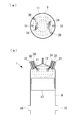
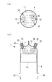
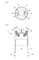
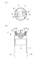
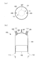
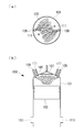
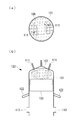
- FIG. 2 is a schematic view of a configuration around a cylinder including a cylinder liner shown in FIG. 1, showing a state in which a premixed fuel gas is injected, (a) is a plan view, and (b) is a longitudinal sectional view. It is the schematic corresponding to FIG. 2, and shows the ignition condition by pilot oil, (a) is a top view, (b) is a longitudinal cross-sectional view. It is the schematic corresponding to FIG. 2, and shows a premix combustion state, (a) is a top view, (b) is a longitudinal cross-sectional view.
- FIG. 2 It is the schematic corresponding to FIG. 2, and shows the process which compresses air, (a) is a top view, (b) is a longitudinal cross-sectional view. It is the schematic corresponding to FIG. 2, and shows the ignition state by pilot oil and the injection state of diffused fuel gas, (a) is a top view, (b) is a longitudinal cross-sectional view. It is the schematic corresponding to FIG. 2, and shows a diffusion combustion state, (a) is a top view, (b) is a longitudinal cross-sectional view. It is the schematic perspective view which showed an example of the injection direction of the fuel gas from a premixed gas valve. FIG. 10 is a schematic perspective view showing another example of the injection direction of fuel gas from the premixed gas valve. FIG.
- FIG. 10 is a schematic perspective view showing another example of the injection direction of fuel gas from the premixed gas valve.
- FIG. 10 is a schematic perspective view showing another example of the injection direction of fuel gas from the premixed gas valve.
- the process which compresses the air of a diffusion combustion type DF engine is shown, (a) is a top view, (b) is a longitudinal cross-sectional view.
- the ignition state by pilot oil of a diffusion combustion type DF engine is shown, (a) is a plan view, (b) is a longitudinal sectional view.
- the diffusion combustion state by the fuel gas of a diffusion combustion type DF engine is shown, (a) is a top view, (b) is a longitudinal cross-sectional view.
- the state which is injecting the premix fuel gas of DF engine of a premix combustion type is shown, (a) is a top view, (b) is a longitudinal cross-sectional view.
- the ignition condition by the pilot oil of DF engine of premix combustion type is shown, (a) is a top view, (b) is a longitudinal cross-sectional view.
- the premix combustion state of a premixed combustion type DF engine is shown, (a) is a plan view, (b) is a longitudinal sectional view.
- FIG. 1 schematically shows a crosshead diesel engine (internal combustion engine) 1 according to an embodiment of the present invention.
- the diesel engine 1 shown in the figure is, for example, a low-speed two-stroke one-cycle uniflow scavenging system used as a marine main vessel of a liquefied gas carrier such as an LNG carrier.
- the diesel engine 1 includes a base plate 3 located below, a frame 5 provided on the base plate 3, and a jacket 7 provided on the frame 5.
- the base plate 3, the frame 5 and the jacket 7 are integrally fastened and fixed by a plurality of tension bolts (not shown) extending in the vertical direction.
- the jacket 7 is provided with a cylinder liner 9, and a plurality of scavenging ports 10 are formed on the lower end side of the cylinder liner 9.
- a cylinder cover 11 is provided at the upper end of the cylinder liner 9.
- the cylinder cover 11 is provided with an exhaust valve 12.
- a uniflow scavenging system is used in which air is introduced into the cylinder from below as scavenging air from the scavenging port 10 provided on the lower end side of the cylinder liner 9 and the combustion exhaust gas is exhausted from the exhaust valve 12 located in the upper side It is adopted.
- the exhaust gas discharged from the exhaust valve 12 is collected in the exhaust gas manifold 14 and then sent to the turbocharger 16.
- the turbocharger 16 the exhaust gas (not shown) is rotated by the introduced exhaust gas, and thereby the coaxially connected compressor (not shown) is rotated.
- the compressor compresses the air taken in from the outside, is cooled by the air cooler 18, and is led to the scavenging manifold 20.
- the compressed air led to the scavenging manifold 20 is led to the scavenging port 10 described above.
- a piston 13 is provided so as to be capable of reciprocating.
- the upper end of the piston rod 15 is rotatably attached to the lower end of the piston 13.
- the super stroke is such that the bore stroke ratio, which is the ratio of the stroke of the piston 13 to the inner diameter of the cylinder liner 9, is 3 or more.
- the base plate 3 is a crankcase, and a crankshaft 17 is provided.
- the rotational output taken from the crankshaft 17 is transmitted to the propulsion propeller of the ship.
- the lower end of the connecting rod 19 is rotatably connected to the upper end of the crankshaft 17.
- the frame 5 is provided with a crosshead 21 that rotatably connects the piston rod 15 and the connecting rod 19. That is, the lower end of the piston rod 15 and the upper end of the connecting rod 19 are connected to the cross head 21.
- a pair of sliding plates 23 extending in the vertical direction is provided on both sides (left and right in FIG. 1) of the cross head 21 in a state of being fixed to the frame 5 side.
- FIG. 2 schematically shows the configuration around the cylinder of the diesel engine 1.
- the cylinder cover 11 includes a fuel gas injection valve for premixing (hereinafter referred to as “premixed gas valve”) 30 as a first fuel gas injection valve, and a second fuel.
- premixed gas valve a fuel gas injection valve for premixing
- second fuel a second fuel.
- a diffusion fuel gas injection valve (hereinafter referred to as “diffusion gas valve”) 32 as a gas injection valve and a fuel oil injection valve (hereinafter referred to as “fuel oil valve”) 34 are provided.
- premixed gas valves 30 are provided on the outer peripheral side of the cylinder cover 11 in plan view.
- the two premixed gas valves 30 are disposed at mutually opposing positions across the center of the cylinder cover 11 (that is, the center of the exhaust valve 12).
- the number of premixed gas valves 30 is only two as an example, and may be one or three or more.
- the premixed gas valve 30 is connected to a fuel gas supply source (not shown), and injects the fuel gas at high pressure into the cylinder formed by the cylinder liner 9 and the cylinder cover 11.
- fuel gas hydrocarbon gas such as vaporized LNG is used.
- the gas injection pressure from the premixed gas valve 30 is 1.0 MPa or more and 50 MPa or less in absolute pressure, and preferably 20 MPa or more and 30 MPa or less in absolute pressure.
- the nozzle provided at the tip of the premixed gas valve 30 is provided with a plurality of injection holes, and fuel gas is injected from the respective injection holes into the cylinder. For example, in the present embodiment shown in FIG. 2B, a state in which the fuel gas is injected from each of the four injection holes is shown.
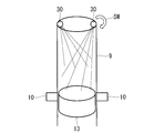
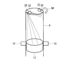
- the direction of the fuel gas injected from the premixed gas valve 30 is the direction of the piston 13, more specifically, the top of the piston 13 after closing the scavenging port 10 with the piston 13, ie, the piston
- the fuel gas is injected toward the top surface of the upper end of the circular shape 13.
- the premixed gas valve 30 may be provided with each injection hole so that the fuel gas is injected from the at least one injection hole in the direction of the piston 13, and all the injection holes are in the direction of the piston 13 It does not have to be provided to inject
- the premixed gas valve 30 is activated when operating the diesel engine 1 by premixed combustion, and is stopped without being activated during diffusion combustion operation with fuel gas or diffusion combustion operation with fuel oil.
- the start and stop of the premixed gas valve 30 are performed by a command from a control unit (not shown).
- the injection timing of the premixed gas valve 30 is controlled by a control unit (not shown) and is set to a range where fuel gas does not leak from the exhaust valve 12 to the outside of the system. Specifically, for example, 140 to 20 deg BTDC (BTDChaBefore Top Dead Center) Preferably, it is 100 or more and 60 deg BTDC or less.
- the timing at which the exhaust valve 12 closes is, for example, about 90 deg BTDC.
- a period which injects fuel gas namely, period which continues injecting fuel gas
- each diffusion gas valve 32 is disposed at a position circumferentially offset from the premixed gas valve 30 by a predetermined angle, but the diffusion gas valve 32 and the premixed gas valve 30 are located on the cylinder cover 11. It should just be arrange
- the number of diffusion gas valves 32 is only two as an example, and may be one or three or more, but the same as the number of fuel oil valves 34 .
- the premixed gas valve 30 is connected to a fuel gas supply source (not shown), and injects the fuel gas into the cylinder formed by the cylinder liner 9 and the cylinder cover 11.
- a fuel gas supply source not shown
- a hydrocarbon-based gas such as vaporized LNG is used.
- the gas injection pressure from the diffusion gas valve 32 is a pressure higher than air (scavenging air) after being compressed by the piston 13 and is 50 MPa or less, for example, 10 MPa or more and 30 MPa or less in absolute pressure.
- the nozzle provided at the tip of the diffusion gas valve 32 is provided with a plurality of injection holes, and fuel gas is injected from the respective injection holes into the cylinder.
- FIG. 7B a state in which the fuel gas is injected from each of the four injection holes is shown.
- the direction of the fuel gas injected from the diffusion gas valve 32 is such that diffusion combustion is performed in the combustion space where the piston 13 is raised to near the top dead center and narrowed.
- the direction is a horizontal direction or a direction slightly downward from the horizontal direction, and is a direction not facing the top of the piston 13.
- the diffusion gas valve 32 is activated when operating the diesel engine 1 by diffusion combustion, and is stopped without being activated in a premixed combustion operation with fuel gas or a diffusion combustion operation with fuel oil.
- the start and stop of the diffusion gas valve 32 are performed by an instruction from a control unit (not shown).
- the diffusion gas valve 32 When the diffusion gas valve 32 is used as a gas valve for premixed combustion, it may be activated at the time of premixed combustion operation (see, for example, FIG. 11).
- a period in which the diffusion gas valve 32 injects the fuel gas is controlled by a control unit (not shown), and is, for example, 20 degrees or more and 30 degrees or less when the load of the diesel engine 1 is 100%.
- the fuel oil valve 34 is located on the outer peripheral side of the exhaust valve 12 and is higher than the premixed gas valve 30 and the diffusion gas valve 32. Two are provided on the inner circumference side. The two fuel oil valves 34 are disposed at positions facing each other across the center of the cylinder cover 11 (that is, the center of the exhaust valve 12). However, each fuel oil valve 34 is disposed at a circumferentially offset position with respect to the diffusion gas valve 32 and the premixed gas valve 30 by a predetermined angle. The number of fuel oil valves 34 is only two as an example, and may be one or three or more. Further, if it is on the outer peripheral side than the exhaust valve 12, it may not be on the inner peripheral side with respect to the premixed gas valve 30 and the diffusion gas valve 32.
- the fuel oil valve 34 is connected to a fuel oil supply source (not shown), and injects the fuel oil into the cylinder formed by the cylinder liner 9 and the cylinder cover 11.
- fuel oil heavy oil, such as C heavy oil, is used, for example.
- the injection pressure from the fuel oil valve 34 is a pressure higher than the air (scavenging air) after being compressed by the piston 13, and is, for example, 30 MPa or more and 80 MPa or less in absolute pressure.
- the nozzle provided at the tip of the fuel oil valve 34 is provided with a plurality of injection holes, and fuel oil is injected from the respective injection holes into the cylinder.
- FIG. 3B a state in which fuel oil is injected from each of the four injection holes is shown.
- the direction of the fuel oil injected from the fuel oil valve 34 is such that ignition or diffusion combustion is performed in the combustion space in which the piston 13 is raised to near the top dead center and narrowed.
- the horizontal direction or the direction slightly downward from the horizontal direction is a direction not directed to the top of the piston 13.
- the fuel oil valve 34 operates to inject fuel oil for diffusion combustion when the diesel engine 1 is operated by diffusion combustion with fuel oil (so-called oil-only combustion operation), and pre-mixed combustion with fuel gas During operation and diffusion combustion operation with fuel gas, it operates to inject pilot oil for ignition.
- the operation of the fuel oil valve 34 is performed by a command from a control unit (not shown).
- a premixed gas valve 30 is mainly used, a premixed fuel gas mode which uses the fuel oil valve 34 for pilot, and a diffused fuel gas which mainly uses the diffusion gas valve 32 and which uses the fuel oil valve 34 for pilot.
- a mode and a diffusion fuel oil mode which exclusively uses the fuel oil valve 34.
- the premixed fuel gas mode is used, for example, when a vessel navigates in the ECA because NOx emissions are low.
- the diffusion fuel gas mode has higher combustion stability than the premix fuel gas mode, but has a larger amount of NOx generation than the premix fuel gas mode, so it is used, for example, when the vessel travels outside the ECA. Further, the diffusion fuel gas mode can be used in place of the premix fuel gas mode when the combustion stability is required as long as it is within a predetermined time within the range not exceeding the NOx control amount even within the ECA.
- SOx derived from fuel oil is generated more than in the case of using fuel gas, so when traveling in a sea area where SOx emission regulations are relatively loose, for example, high combustion stability is required or It is used when it is better to use fuel oil than fuel gas.
- the premixed fuel gas mode will be described using FIGS. 2 to 4.
- the pressure from the premixed gas valve 30 is A fuel gas of a high pressure of 1.0 MPa to 50 MPa, preferably an absolute pressure of 20 MPa to 30 MPa, is injected toward the top of the piston 13.
- the diffusion gas valve 32 is closed.
- the diffusion gas valve 32 may be used in combination.
- the injection timing of the fuel gas from the premixed gas valve 30 is selected within a range in which the fuel gas does not leak out of the system from the exhaust valve 12 after the piston 13 closes the scavenging port 10, for example 140 or more and 20 degrees BTDC or less Preferably, it is selected between 100 and 60 deg BTDC. In this case, the timing at which the exhaust valve 12 closes is about 90 deg BTDC.
- the injection period in which the fuel gas continues to be injected from the premixed gas valve 30 is, for example, 20 degrees or more and 30 degrees or less when the load of the internal combustion engine is 100%.
- the premixed gas valve 30 injects from the upper cylinder cover 11 toward the top of the lower piston 13, the longitudinal direction of the longitudinally elongated combustion space after closing the scavenging port 10 with the piston 13 is effectively used.
- the fuel gas can be injected to the whole, and the mixing of the fuel gas with the air (scavenging gas; oxidant gas) is promoted.
- the diesel engine 1 of the present embodiment has an extremely long stroke, mixing by fuel gas injection in the longitudinal direction is considered effective.
- the piston 13 moves upward to compress the premixed air. Then, as shown in FIG. 3, when reaching near the top dead center, pilot oil is injected from the fuel oil valve 34 and ignition is performed. Premixed combustion is performed while the flame formed by this ignition propagates in the premixed air, and the combustion and expansion strokes are performed as shown in FIG. 4 (at this time, the injection of pilot oil from the fuel oil valve 34 is (Stopped), the piston 13 moves downward.
- the diffusion fuel oil mode (so-called oil-only combustion mode) is not shown, but is similar to diffusion combustion using a common fuel oil. Specifically, the exhaust valve 12 is closed to compress air as the piston 13 ascends, and fuel oil is injected from the fuel oil valve 34 at high pressure near the top dead center to perform diffusion combustion, and expansion by this diffusion combustion The piston 13 is lowered by the stroke.
- the diesel engine 1 can be established as a dual fuel engine (DF engine) used in combination with the operation using fuel gas.
- DF engine dual fuel engine
- the premixed gas valve 30 and the diffusion gas valve 32 are always closed.
- the diesel engine 1 of the present embodiment further includes premixed transition control performed when transitioning from the diffused fuel gas mode or the diffused fuel oil mode to the premixed fuel gas mode.
- the fuel gas injected from the diffusion gas injection valve 32 is reduced and the fuel gas injected from the premix gas valve 30 is increased. That is, at the time of switching from the diffusion fuel gas mode to the premix fuel gas mode, the premix ratio, which is the ratio of the fuel gas injected from the premix gas valve 30 to the total fuel gas to be injected, is 0% (only diffusion combustion (Diffusion fuel gas mode) to increase to 100% (premixed fuel gas mode of only premixed combustion).
- the fuel gas injected from the premixed gas valve 30 is completely burned in the combustion stroke in the first cycle immediately after switching from the diffusion fuel gas mode to the premixed fuel gas mode by the premixed transfer control by the control unit.
- the amount of fuel gas injected from the pre-mixture gas valve 30 is increased to the concentration at which the pre-mixture ratio is rapidly increased.
- the premixing ratio is rapidly raised from 0% to 40% or more and 60% or less.
- the premixing ratio is gradually increased in a plurality of subsequent cycles.
- the same control is performed when switching from the diffusion fuel oil mode using fuel oil to the premix fuel gas mode. That is, when switching from the diffusion fuel oil mode to the mixed fuel gas mode, the fuel oil injected from the fuel oil valve 34 is decreased and the fuel gas injected from the premixed gas valve 30 is increased. That is, at the time of switching from the diffusion fuel oil mode to the premix fuel gas mode, the premix ratio, which is the calorific value ratio of the fuel gas injected from the premix gas valve 30 to the total fuel injected, is 0% (only diffusion combustion (Diffusion fuel oil mode) to 100% (premixed fuel gas mode only in premixed combustion).
- the fuel gas injected from the premixed gas valve 30 is completely burned in the combustion stroke in the first cycle immediately after switching from the diffusion fuel oil mode to the premixed fuel gas mode by the premixed transfer control by the control unit.
- the amount of fuel gas injected from the pre-mixture gas valve 30 is increased to the concentration at which the pre-mixture ratio is rapidly increased.
- the premixing ratio is rapidly raised from 0% to 40% or more and 60% or less.
- the premixing ratio is gradually increased in a plurality of subsequent cycles.
- the fuel gas injected from all the injection holes (four in the drawing) of the premixed gas valve 30 is injected toward the top of the piston 13.
- Fuel gas is injected.
- the direction in which the fuel gas is injected is the direction along the swirl direction SW of the air introduced from the scavenging port 10, and is injected so as to be placed on the swirl air.
- the timings at which the fuel gas is injected from the left and right premixed gas valves 30 may be different.
- the combustion gas can be respectively injected at the timing when the piston position becomes different as the piston 13 ascends, mixing of the fuel gas can be promoted.
- the injection pressure at the time of injecting the fuel gas from the left and right premixed gas valves 30 may be made different. Thereby, the arrival position of the fuel gas injected from the left and right premixed gas valves 30 can be adjusted, and the mixing of the fuel gas can be promoted. Further, the mixing of fuel gas may be promoted with the direction of the fuel gas injected from the premixed gas valve 30 as the direction opposite to the swirl direction SW of air.
- the directions in which the fuel gas is injected from the left and right premixed gas valves 30 are made different in the longitudinal direction.
- the fuel gas can be mixed by effectively using the longitudinal direction of the combustion space which has been made longitudinally.
- the direction of the injection holes may be changed, or by making the diameters of the injection holes different at the left and right premixed gas valves 30 even in the same direction of the injection holes.
- the timing to inject fuel gas from the left and right premixed gas valves 30 may be the same as or different from the timing at which the mixing of the fuel gas is good.
- the fuel gas is injected from the premixed gas valve 30 in such a direction that the mixing of the fuel gas is good, and may be a direction along the swirl direction SW of air or may be a direction opposite thereto.
- some of the plurality of injection holes are directed to the top of the piston 13, and the other injection holes are directed horizontally inclined upwards.
- the fuel gas can be mixed by effectively using the longitudinal direction of the combustion space which has been made longitudinally.
- the fuel gas is similarly injected from the premixed gas valve 30 on the right side in a direction symmetrical to the axis of the cylinder liner 9. Ru.
- the diameter of the injection hole inclined in the horizontal direction without going to the top of the piston 13 may be smaller than the diameter of the injection hole toward the top of the piston 13.
- the timing to inject fuel gas from the left and right premixed gas valves 30 may be the same as or different from the timing at which the mixing of the fuel gas is good. Further, the fuel gas is injected from the premixed gas valve 30 in such a direction that the mixing of the fuel gas is good, and may be a direction along the swirl direction SW of air or may be a direction opposite thereto.
- a diffusion gas valve 32 is used in addition to the premixed gas valve 30, in addition to the premixed gas valve 30, a diffusion gas valve 32 is used.
- the injection pattern of the premixed gas valve 30 any one of FIGS. 8 to 10 described above may be used. Since the diffusion gas valve 32 injects fuel to perform ignition and diffusion combustion when the piston 13 moves up to the cylinder cover 11 side, the injection direction of the fuel gas is a region on the cylinder cover 11 side in the cylinder (specifically In the upper region of the cylinder).
- the diffusion gas valve 32 also in the premixed fuel gas mode by utilizing the injection direction of the diffusion gas valve 32, it is possible to promote mixing in the upper region on the cylinder cover 11 side in the cylinder.
- the injection timing may be simultaneous injection of the premixed gas valve 30 and the diffusion gas valve 32, or after injecting the premixed gas valve 30 first, the diffusion gas valve 32 at the timing when the piston 13 rises to a predetermined position. May be injected.
- the premixed gas valve 30 is provided on the cylinder cover 11, and fuel gas is injected from the upper side to the lower side toward the top of the piston 13 after the scavenging port 10 is closed by the piston 13.
- the fuel gas can be injected to the whole by effectively using the piston reciprocating direction of the combustion space after the scavenging port 10 is closed by the piston 13, and the mixing of the fuel gas and the air is promoted.
- the diesel engine 1 has an extremely long stroke, and the combustion space has a long shape in the piston reciprocating direction, so that the fuel gas can be effectively mixed by effectively using the longitudinal direction of the combustion space.
- the fuel gas is injected at a high pressure of 1.0 MPa or more and 50 MPa or less in absolute pressure, and more preferably 20 MPa or more and 30 MPa or less in absolute pressure, mixing of fuel gas is further promoted. Therefore, the local minimum ⁇ (where ⁇ is the excess air ratio) at which the fuel gas concentration increases locally can be increased, and combustion stability can be avoided by avoiding abnormal combustion such as pre-ignition or knocking as much as possible. Can be improved. In addition, since abnormal combustion such as pre-ignition and knocking can be avoided as much as possible, the reduction ratio of the compression ratio can be made smaller than that of the conventional premixed engine, and the reduction of the thermal efficiency can be minimized. It is also possible to operate at a high load, which is defined as the in-cylinder average effective pressure).
- the premixed gas valve 30 is provided on the cylinder cover 11 in the same manner as the exhaust valve 12 and injects the fuel gas in a direction away from the exhaust valve 12, so that the exhaust valve 12 is not completely closed. Can also start the injection of fuel gas. As described above, if the injection of the fuel gas is started before the exhaust valve 12 is closed, a long time for mixing the fuel gas with the air can be secured, so that the mixing can be performed more uniformly.
- the premixed fuel gas mode and the diffusion fuel gas mode can be used according to the situation, the premixed combustion gas mode is selected when used in the ECA, and NOx in the exhaust gas is below the regulation value. Driving can be done. This eliminates the need for an exhaust gas processing apparatus such as SCR for removing NOx, and additional equipment such as EGR for reducing NOx.
- the diffusion fuel gas mode can be selected to perform an operation with higher combustion stability.
- a fuel oil mode for performing diffusion combustion using the fuel oil valve 34 is provided, and a diesel engine 1 as a DF engine provided with a fuel oil mode and a fuel gas mode (premixed fuel gas mode and diffusion fuel gas mode) Therefore, by selecting the fuel oil mode, it is possible to perform an operation with higher combustion stability. On the other hand, if the fuel gas mode is selected, the discharge of SOx derived from the fuel oil can be avoided, and the operating time of the fuel oil mode can be reduced to reduce the fuel oil cost.
- the amount of fuel gas injected from the premixed gas valve 30 to the concentration at which the fuel gas completely burns in the combustion stroke in the first cycle immediately after switching from the diffusion fuel gas mode or the diffusion fuel oil mode to the premixed fuel gas mode Since the increased premixed transfer control is adopted, it is possible to prevent the unburned gas from being exhausted from the exhaust valve 12 at the time of switching from the diffusion fuel gas mode to the premixed fuel gas mode.
- the premixed gas valve 30 and the diffusion gas valve 32 are described as separate gas valves, but the premixed gas valve 30 and the diffusion gas valve 32 are used as a common gas valve. May be In such a case, the directions of the plurality of injection holes formed in the common gas valve are separately set for premixing and diffusion, and the injection holes are switched.
- Diesel engine internal combustion engine 9 cylinder liner 10 scavenging port 11 cylinder cover 12 exhaust valve 13 piston 14 exhaust gas manifold 16 supercharger 30 premixed gas valve (first fuel gas injection valve) 32 Diffusion gas valve (second fuel gas injection valve) 34 Fuel oil valve (fuel oil injection valve)
Landscapes
- Engineering & Computer Science (AREA)
- Chemical & Material Sciences (AREA)
- Combustion & Propulsion (AREA)
- Mechanical Engineering (AREA)
- General Engineering & Computer Science (AREA)
- Oil, Petroleum & Natural Gas (AREA)
- Chemical Kinetics & Catalysis (AREA)
- General Chemical & Material Sciences (AREA)
- Output Control And Ontrol Of Special Type Engine (AREA)
- Electrical Control Of Air Or Fuel Supplied To Internal-Combustion Engine (AREA)
- Combustion Methods Of Internal-Combustion Engines (AREA)
Abstract
筒内における予混合気の混合を促進して燃焼安定性を向上させた内燃機関を提供する。内燃機関(1)が、シリンダライナ(9)内を往復動するピストン(13)と、シリンダライナ(9)の一端側に設けられたシリンダカバー(11)と、シリンダカバー(11)に設けられた排気弁(12)と、シリンダライナ(9)の他端側に設けられた掃気ポート(10)と、シリンダカバー(11)に設けられ、シリンダライナ(9)及びシリンダカバー(11)によって形成される筒内に燃料ガスを噴射する予混合ガス弁(30)とを備え、予混合ガス弁(30)は、シリンダカバー(11)に設けられ、掃気ポート(10)をピストン(13)で閉じた後のピストン(13)に向けて燃料ガスを高圧で噴射する。
Description
本発明は、燃料ガスを用いて予混合燃焼を行う内燃機関およびこれを備えた船舶に関するものである。
近年、LNG(液化天然ガス)等の液化ガス運搬船の需要を見込んで舶用主機としてデュアルフューエル機関(以下「DF機関」という。)の開発が行われている(下記特許文献1及び2参照)。DF機関は、燃料油の燃焼を行う燃料油モードと、LNG等の燃料ガスの燃焼を行う燃料ガスモードとを備えている。なお、燃料ガスモードでは、着火用のパイロット燃料として燃料油が用いられるのが一般的である。
液化ガス運搬船の舶用主機として用いられるDF機関は、定格における回転数が200rpm以下とされた低速2ストロークディーゼル機関が用いられる。このようなDF機関は、燃料ガスモードを行う際に燃料ガスの拡散燃焼を行う拡散燃焼タイプと、燃料ガスの予混合燃焼を行う予混合燃焼タイプが存在する。
図12には、拡散燃焼タイプのDF機関が示されている。
拡散燃焼タイプのDF機関100は、シリンダライナ101と、シリンダライナ101内を往復動するピストン103とを備えている。シリンダライナ101の上端にはシリンダカバー105が設けられており、このシリンダカバー105には、1つの排気弁107と、2つの拡散用燃料ガス噴射弁109と、2つの燃料油弁111とが設けられている。また、シリンダライナ103の下方には掃気ポート113が設けられている。
拡散燃焼タイプのDF機関100は、シリンダライナ101と、シリンダライナ101内を往復動するピストン103とを備えている。シリンダライナ101の上端にはシリンダカバー105が設けられており、このシリンダカバー105には、1つの排気弁107と、2つの拡散用燃料ガス噴射弁109と、2つの燃料油弁111とが設けられている。また、シリンダライナ103の下方には掃気ポート113が設けられている。
図12のように、ピストン103によって掃気ポート113が閉じられて排気弁107も閉じられた後にピストン103が上昇することによって筒内の空気が圧縮される。そして、図13に示すように、ピストン103が上死点付近まで到達すると、燃料油弁111から燃料油をパイロット油として噴射するとともに、このパイロット油と同時または直後に、拡散用燃料ガス噴射弁109から例えば約30MPa程度の高圧とされた燃料ガスを噴射する。これにより、図14に示すように、燃料ガスの噴射に応じて筒内で拡散燃焼が行われ(このとき燃料油弁111からのパイロット油の噴射は停止されている)、膨張行程によってピストン103が下方へと押し下げられる。
このような燃料ガスによる拡散燃焼は、ディーゼル機関の燃料油による拡散燃焼と同等レベルの燃焼安定性を有するという利点を有する。
しかし、燃料ガスによる拡散燃焼を用いたディーゼル機関は、燃料油による拡散燃焼を用いたディーゼル機関に比べて20~30%程度のNOx(窒素酸化物)を減らすことはできるが、拡散燃焼を用いるためNOx排出量が依然として多く、特に舶用主機として用いる場合には国際海事機関(IMO)が定めたTier IIIを満足することができない。したがって、上記Tier IIIが適用される排ガス規制海域(ECA;Emission Control Area)では、何らかのNOx排出低減対策を行わなければ運転することができないという問題がある。
NOx排出量を低減するには、SCR(Selective Catalytic Reduction;選択式触媒還元)等の排ガス処理装置や、NOxを低減するためのEGR(Exhaust Gas Recirculation;排ガス再循環)等の付帯設備を追加することが考えられるが、イニシャルコストやランニングコストが増大することになる。
しかし、燃料ガスによる拡散燃焼を用いたディーゼル機関は、燃料油による拡散燃焼を用いたディーゼル機関に比べて20~30%程度のNOx(窒素酸化物)を減らすことはできるが、拡散燃焼を用いるためNOx排出量が依然として多く、特に舶用主機として用いる場合には国際海事機関(IMO)が定めたTier IIIを満足することができない。したがって、上記Tier IIIが適用される排ガス規制海域(ECA;Emission Control Area)では、何らかのNOx排出低減対策を行わなければ運転することができないという問題がある。
NOx排出量を低減するには、SCR(Selective Catalytic Reduction;選択式触媒還元)等の排ガス処理装置や、NOxを低減するためのEGR(Exhaust Gas Recirculation;排ガス再循環)等の付帯設備を追加することが考えられるが、イニシャルコストやランニングコストが増大することになる。
図15には、予混合燃焼タイプのDF機関120が示されている。なお、図12~図14を用いて説明した拡散燃焼タイプのDF機関100と同様の構成については同一符号を付してある。
予混合燃焼タイプのDF機関120は、図12等に示した拡散燃焼タイプのDF機関100に対して、燃料ガスを噴射する噴射弁の位置が異なる。具体的には、予混合燃焼タイプのDF機関120は、シリンダライナ101の側部でかつ掃気ポート113の上方に、2つの予混合用燃料ガス噴射弁122が設けられている。
予混合燃焼タイプのDF機関120は、図12等に示した拡散燃焼タイプのDF機関100に対して、燃料ガスを噴射する噴射弁の位置が異なる。具体的には、予混合燃焼タイプのDF機関120は、シリンダライナ101の側部でかつ掃気ポート113の上方に、2つの予混合用燃料ガス噴射弁122が設けられている。
図15のように、ピストン103によって掃気ポート113が閉じられた後に、予混合用燃料ガス噴射弁122から燃料ガスが噴射される。予混合燃料ガス噴射弁122から噴射される燃焼ガスは、略水平方向に向けて例えば1.0MPa未満の低圧で噴射される。これにより、掃気ポート113から導入された空気と燃料ガスとが予混合される。そして、図16のようにピストン103が上昇するに従い予混合気が圧縮され、ピストン103が上死点付近まで到達すると、燃料油弁111からパイロット油が噴射されて着火が行われる。これにより、図17に示すように、筒内で火炎面伝播による予混合燃焼が行われ(このとき燃料油弁111からのパイロット油の噴射は停止されている)、膨張行程によってピストン103が下方へと押し下げられる。
このような燃料ガスによる予混合燃焼は、NOx排出量が低く、上述したSCRやEGRを用いなくても機関単独で上記Tier IIIを達成することができるという利点を有する。
しかし、予混合燃焼タイプのDF機関120は、予混合燃焼特有の過早着火やノッキング等の異常燃焼が発生するリスクがあり、拡散燃焼に比べて燃焼安定性が悪いという問題がある。
また、予混合燃焼タイプのDF機関120は、低圧とされた燃料ガスを噴射する構成となっているので、空気(掃気)に対する燃料ガスの混合が不十分となり混合気濃度が不均一になりやすい。過早着火やノッキング等の異常燃焼は局所的にガス濃度が高い(空気過剰率λが低い)位置で発生しやすいことが知られており、低圧とされた燃料ガスを噴射するだけでは混合気濃度が不均一となるため異常燃焼が発生する可能性が高くなる。
しかし、予混合燃焼タイプのDF機関120は、予混合燃焼特有の過早着火やノッキング等の異常燃焼が発生するリスクがあり、拡散燃焼に比べて燃焼安定性が悪いという問題がある。
また、予混合燃焼タイプのDF機関120は、低圧とされた燃料ガスを噴射する構成となっているので、空気(掃気)に対する燃料ガスの混合が不十分となり混合気濃度が不均一になりやすい。過早着火やノッキング等の異常燃焼は局所的にガス濃度が高い(空気過剰率λが低い)位置で発生しやすいことが知られており、低圧とされた燃料ガスを噴射するだけでは混合気濃度が不均一となるため異常燃焼が発生する可能性が高くなる。
これに対して、上記特許文献1では、ガス噴射弁が設けられた高さ位置からシリンダ軸方向に対して直交する方向に向けて燃料ガスを低圧で噴射することで、ホットスポットとなるシリンダ頂部や排気弁へと燃料ガスを向かわせずに掃気ポートから導入した掃気に混合させることで、燃料ガスを高圧にせずに予混合を行わせることが開示されている。しかし、この特許文献1に記載された噴射方法であっても、燃料ガスの噴射方向が水平方向であるため、燃焼空間の上部(図15(b)の符号Aで示した領域)が有効に利用されておらず、予混合が十分でないという問題がある。
したがって、予混合燃焼を用いるDF機関では、異常燃焼を回避するために圧縮比を下げて運転をせざるを得ず、熱効率が低下するという問題がある。
また、高いPme(筒内平均有効圧力)とされた高負荷での運転になるほど異常燃焼が発生しやすくなり燃焼安定性が悪化するため、上述のように幾何学的圧縮比を下げても高負荷運転が困難となり、さらに負荷(即ちPme)に制約を設ける必要が生じる。特に、舶用主機としてDF機関を用いる場合、上記Tier IIIが適用されるECAでは、高負荷運転を行うことができず、船舶の運転の自由度を下げてしまうという問題がある。
また、高いPme(筒内平均有効圧力)とされた高負荷での運転になるほど異常燃焼が発生しやすくなり燃焼安定性が悪化するため、上述のように幾何学的圧縮比を下げても高負荷運転が困難となり、さらに負荷(即ちPme)に制約を設ける必要が生じる。特に、舶用主機としてDF機関を用いる場合、上記Tier IIIが適用されるECAでは、高負荷運転を行うことができず、船舶の運転の自由度を下げてしまうという問題がある。
本発明は、このような事情に鑑みてなされたものであって、筒内における予混合気の混合を促進して燃焼安定性を向上させた内燃機関およびこれを備えた船舶を提供することを目的とする。
本発明の第1態様は、シリンダライナと、該シリンダライナ内を往復動するピストンと、前記シリンダライナの一端側に設けられたシリンダカバーと、該シリンダカバーに設けられた排気弁と、前記シリンダライナの他端側に設けられた掃気ポートと、前記シリンダカバーに設けられ、前記シリンダライナ及び前記シリンダカバーによって形成される筒内に燃料ガスを予混合燃焼用燃料として噴射する第1の燃料ガス噴射弁とを備え、前記第1の燃料ガス噴射弁は、前記掃気ポートを前記ピストンで閉じた後の該ピストンに向けて前記燃料ガスを噴射する内燃機関である。
本発明の第1態様では、第1の燃料ガス噴射弁をシリンダカバーに設け、掃気ポートをピストンで閉じた後のピストンに向けて(例えば上方から下方に向けて)燃料ガスを噴射することとした。これにより、掃気ポートをピストンで閉じた後の燃焼空間のピストン往復動方向(例えば上下方向)を有効に使って燃料ガスを全体に噴射することができ、酸化剤ガスに対する燃料ガスの混合が促進される。したがって、局所的に燃料ガス濃度が高くなる局所的最小λ(λは空気過剰率)を大きくすることができ、過早着火やノッキング等の異常燃焼を可及的に回避することで燃焼安定性を向上させることができる。また、過早着火やノッキング等の異常燃焼を可及的に回避することができるので、従来の予混合機関よりも圧縮比の下げ代を小さくでき、熱効率の低下を最小化でき、高いPme(筒内平均有効圧力)とされた高負荷での運転も可能となる。
燃料ガスを噴射するタイミングとしては、掃気ポートをピストンが閉じた後でかつ排気弁から燃料ガスが系外にリークしない範囲が好ましく、具体的には例えば140以上20degBTDC以下(BTDCはBefore Top Dead Centre)、好ましくは100以上60degBTDC以下とされる。なお、本態様の第1の燃料ガス噴射弁は、排気弁と同様にシリンダカバーに設けられており、排気弁から遠ざかるように燃料ガスを噴射することになるので、排気弁が完全に閉じる前であっても燃料ガスの噴射を開始することができる。このように排気弁が閉じる前に燃料ガスの噴射を開始することとすれば、燃料ガスを酸化剤ガスに対して混合させる時間を多く確保することができるので、より均一に混合することができる。排気弁が閉じるタイミングとしては例えば約90degBTDCである。
燃料ガスを噴射する期間(即ち噴射し続ける期間)としては、例えば内燃機関の負荷が100%の場合には20deg以上30deg以下とされる。
燃料ガスを噴射する噴孔が第1の燃料ガス噴射弁に複数設けられている場合には、少なくとも1つの噴孔から噴射される燃料ガスが掃気ポートを閉じた後のピストンに向けられていれば良い。
内燃機関としては、例えば、掃気ポートから酸化剤ガスを筒内に導入し、第1の燃料ガス噴射弁から燃料ガスを筒内の酸化剤ガスに対して噴射し、燃焼後の燃焼ガスを排気弁から排出するユニフロー掃気型が用いられる。
燃料ガスを噴射するタイミングとしては、掃気ポートをピストンが閉じた後でかつ排気弁から燃料ガスが系外にリークしない範囲が好ましく、具体的には例えば140以上20degBTDC以下(BTDCはBefore Top Dead Centre)、好ましくは100以上60degBTDC以下とされる。なお、本態様の第1の燃料ガス噴射弁は、排気弁と同様にシリンダカバーに設けられており、排気弁から遠ざかるように燃料ガスを噴射することになるので、排気弁が完全に閉じる前であっても燃料ガスの噴射を開始することができる。このように排気弁が閉じる前に燃料ガスの噴射を開始することとすれば、燃料ガスを酸化剤ガスに対して混合させる時間を多く確保することができるので、より均一に混合することができる。排気弁が閉じるタイミングとしては例えば約90degBTDCである。
燃料ガスを噴射する期間(即ち噴射し続ける期間)としては、例えば内燃機関の負荷が100%の場合には20deg以上30deg以下とされる。
燃料ガスを噴射する噴孔が第1の燃料ガス噴射弁に複数設けられている場合には、少なくとも1つの噴孔から噴射される燃料ガスが掃気ポートを閉じた後のピストンに向けられていれば良い。
内燃機関としては、例えば、掃気ポートから酸化剤ガスを筒内に導入し、第1の燃料ガス噴射弁から燃料ガスを筒内の酸化剤ガスに対して噴射し、燃焼後の燃焼ガスを排気弁から排出するユニフロー掃気型が用いられる。
本発明の第1態様の内燃機関では、前記シリンダライナの内径に対する前記ピストンのストロークの比であるボアストローク比が3以上としてもよい。
ボアストローク比が3以上といった超ロングストロークが用いられる。このため、掃気ポートをピストンで閉じた後の燃焼空間はピストンの往復動方向に伸びた縦長の形状となる。したがって、このようなディーゼルエンジンに燃料ガスを用いた予混合燃焼方式を採用する場合、燃料ガスを酸化剤ガス(例えば空気)に対して均一に混合することが困難となる。
本発明の第1態様では、第1の燃料ガス噴射弁をシリンダカバーに設け、掃気ポートを閉じた後のピストンに向けて(例えば上方から下方に向けて)燃料ガスを噴射することとしているので、超ロングストロークであっても燃焼空間のピストン往復動方向(例えば上下方向)を有効に使って燃料ガスを全体に噴射することができ、酸化剤ガスに対する燃料ガスの混合を促進することができる。
本発明の第1態様の内燃機関としては、例えば、定格にて200rpm以下で運転される低速2ストロークディーゼルエンジンが用いられ、主に舶用主機に採用される。
本発明の第1態様では、第1の燃料ガス噴射弁をシリンダカバーに設け、掃気ポートを閉じた後のピストンに向けて(例えば上方から下方に向けて)燃料ガスを噴射することとしているので、超ロングストロークであっても燃焼空間のピストン往復動方向(例えば上下方向)を有効に使って燃料ガスを全体に噴射することができ、酸化剤ガスに対する燃料ガスの混合を促進することができる。
本発明の第1態様の内燃機関としては、例えば、定格にて200rpm以下で運転される低速2ストロークディーゼルエンジンが用いられ、主に舶用主機に採用される。
本発明の第1態様の内燃機関では、前記第1の燃料ガス噴射弁から噴射される燃料ガスの圧力は、絶対圧で1.0MPa以上50MPa以下とすることができる。
絶対圧で1.0MPa以上50MPa以下とされた高圧で燃料ガスを噴射することとしたので、酸化剤ガスに対する混合をより促進することができる。噴射圧力としては、より好ましくは絶対圧で20MPa以上30MPa以下とされる。
本発明の第1態様の内燃機関では、前記シリンダカバーに、前記筒内に燃料油を噴射する燃料油用噴射弁を設けてもよい。
シリンダカバーに設けられた燃料油用噴射弁から噴射される燃料油は、燃料ガスによる予混合燃焼時にパイロット用油として用いられる。すなわち、燃料用噴射弁から噴射される燃料油によって着火が行われる。
燃料油用噴射弁から噴射される燃料油を拡散燃焼用燃料として用いて内燃機関を運転する燃料油モード(いわゆる油専焼モード)を備えることにより、燃料油モードと燃料ガスモードとを備えたデュアルフューエル機関(DF機関)として内燃機関を用いることができる。
DF機関として用いた場合には、燃料油モードを選択することによりさらに燃焼安定性の高い運転を行うことができる。一方、燃料ガスモードを選択すれば、燃料油由来のSOxの排出を回避でき、また燃料油モードの運転時間を低減して燃料油コストを抑えることができる。
燃料油用噴射弁から噴射される燃料油を拡散燃焼用燃料として用いて内燃機関を運転する燃料油モード(いわゆる油専焼モード)を備えることにより、燃料油モードと燃料ガスモードとを備えたデュアルフューエル機関(DF機関)として内燃機関を用いることができる。
DF機関として用いた場合には、燃料油モードを選択することによりさらに燃焼安定性の高い運転を行うことができる。一方、燃料ガスモードを選択すれば、燃料油由来のSOxの排出を回避でき、また燃料油モードの運転時間を低減して燃料油コストを抑えることができる。
本発明の第1態様の内燃機関は、前記シリンダカバーに、前記筒内に燃料ガスを噴射する第2の燃料ガス噴射弁がさらに設けられ、前記第2の燃料ガス噴射弁を用いて燃焼を行う拡散燃料ガスモードと、前記第1の燃料ガス噴射弁を用いて燃焼を行う予混合燃料ガスモードとを切り替える制御部を備えていてもよい。
第2の燃料ガス噴射弁によって筒内に燃料ガスを噴射することにより、予混合燃焼よりも燃焼安定性が高い拡散燃焼を行わせることができる。上述した燃料油噴射弁が設けられている場合には、この燃料油噴射弁から噴射される燃料油が燃料ガスによる拡散燃焼時のパイロット油として用いられる。
第1の燃料ガス噴射弁と第2の燃料ガス噴射弁とを切り替えることにより、予混合燃焼を行う予混合燃料ガスモードと拡散燃焼を行う拡散燃料ガスモードとを状況に応じて使い分けることができる。
例えば、ECAのように排ガス規制が適用される領域で用いられる場合には、予混合燃焼ガスモードを選択し、排ガス中のNOxを規制値以下にして運転を行うことができる。これにより、NOxを除去するためのSCR等の排ガス処理装置や、NOxを低減するためのEGR等の付帯設備が不要となる。一方、排ガス規制が適用されない領域では、拡散燃料ガスモードを選択し、より燃焼安定性の高い運転を行うことができる。
拡散用燃料ガス噴射弁から噴射される燃料ガスの圧力は、圧縮時の筒内圧以上50MPa(絶対圧)以下、より好ましくは絶対圧で10MPa以上30MPa以下とされる。
第1の燃料ガス噴射弁と第2の燃料ガス噴射弁とを切り替えることにより、予混合燃焼を行う予混合燃料ガスモードと拡散燃焼を行う拡散燃料ガスモードとを状況に応じて使い分けることができる。
例えば、ECAのように排ガス規制が適用される領域で用いられる場合には、予混合燃焼ガスモードを選択し、排ガス中のNOxを規制値以下にして運転を行うことができる。これにより、NOxを除去するためのSCR等の排ガス処理装置や、NOxを低減するためのEGR等の付帯設備が不要となる。一方、排ガス規制が適用されない領域では、拡散燃料ガスモードを選択し、より燃焼安定性の高い運転を行うことができる。
拡散用燃料ガス噴射弁から噴射される燃料ガスの圧力は、圧縮時の筒内圧以上50MPa(絶対圧)以下、より好ましくは絶対圧で10MPa以上30MPa以下とされる。
本発明の第1態様の内燃機関では、前記制御部は、前記予混合燃料ガスモードに切り替えた直後の最初のサイクルにおける燃焼行程にて前記第1の燃料ガス噴射弁から噴射される燃料ガスが完全燃焼する濃度まで、該第1の燃料ガス噴射弁から噴射される燃料ガス量を増大させることとしてもよい。
拡散燃焼を行う拡散燃料ガスモードや拡散燃料油モードのように予混合燃料ガスを用いないモードから、予混合燃焼を行う予混合燃料ガスモードに切り替える際には、以下のように動作する。例えば拡散燃焼を行う拡散燃料ガスモードから予混合燃料ガスモードに切り替える際には、第2の燃料ガス噴射弁から噴射する燃料ガスを減少させるとともに第1の燃料ガス噴射弁から噴射する燃料ガスを増大させる。すなわち、拡散燃料ガスモードから予混合燃料ガスモードへの切換時には、噴射する全燃料ガス中のうち第1の燃料ガス噴射弁から噴射される燃料ガスの割合である予混合割合を0%(拡散燃焼のみ)から100%(予混合燃焼のみ)に向かって複数のサイクルにわたって増大させていくことが考えられる。このとき、予混合割合を複数のサイクルにわたって徐々に増加させていくと、予混合割合が小さい初期のサイクルの場合には第1の燃料ガス噴射弁から噴射される燃料ガス量が少なく予混合濃度が低いため燃料ガスを完全燃焼させることができず未燃の燃料ガスを排気弁から排出してしまうおそれがある。
そこで、本発明の第1態様において、拡散燃料ガスモードから予混合燃料ガスモードに切り替えた直後の最初のサイクルにおける燃焼行程にて燃料ガスが完全燃焼する濃度まで第1の燃料ガス噴射弁から噴射する燃料ガス量を増大させることにより、拡散燃料ガスモードから予混合燃料ガスモードへの切替時に未燃ガスが排気弁から排出されることを防止することができる。
例えば、切替直後の予混合割合は40%以上60%以下とされる。切替直後に40%以上60%以下の予混合割合とした後は、続く複数のサイクルにて徐々に予混合割合を増大させることが好ましい。
そこで、本発明の第1態様において、拡散燃料ガスモードから予混合燃料ガスモードに切り替えた直後の最初のサイクルにおける燃焼行程にて燃料ガスが完全燃焼する濃度まで第1の燃料ガス噴射弁から噴射する燃料ガス量を増大させることにより、拡散燃料ガスモードから予混合燃料ガスモードへの切替時に未燃ガスが排気弁から排出されることを防止することができる。
例えば、切替直後の予混合割合は40%以上60%以下とされる。切替直後に40%以上60%以下の予混合割合とした後は、続く複数のサイクルにて徐々に予混合割合を増大させることが好ましい。
本発明の第1態様の内燃機関では、前記第1の燃料ガス噴射弁から燃料ガスを噴射し、かつ、前記第2の燃料ガス噴射弁から予混合燃料として燃料ガスを噴射することとしてもよい。
第1の燃料ガス噴射弁から予混合燃料として燃料ガスを噴射して燃焼空間内のピストン往復動方向を有効に使って燃料ガスを酸化剤ガスに対して均一に混合することができる。しかし、第1の燃料ガス噴射弁はシリンダカバーに設けられているため、筒内のシリンダカバー側の領域は燃料ガスの混合が比較的悪くなるおそれがある。一方、第2の燃料ガス噴射弁は、ピストンがシリンダカバー側に上昇した際に燃料を噴射して拡散燃焼を行うものなので、燃料ガスの噴射方向は筒内におけるシリンダカバー側の領域(具体的には筒内の上方領域)に向いており、このため、第2の燃料ガス噴射弁によって筒内のシリンダカバー側の領域の混合を促進することができる。
そこで、本発明の第1態様は、第1の燃料ガス噴射弁から予混合燃料として燃料ガスを噴射し、さらに、第2の燃料ガス噴射弁から予混合燃料として燃料ガスを噴射することで、燃焼空間の全体を均一に混合させることができる。
第1の燃料ガス噴射弁から燃料ガスを噴射した後に、第2の燃料ガス噴射弁から予混合燃料として燃料ガスを噴射することとして、燃料ガスを順次噴射することによって混合をさらに促進することが好ましい。
そこで、本発明の第1態様は、第1の燃料ガス噴射弁から予混合燃料として燃料ガスを噴射し、さらに、第2の燃料ガス噴射弁から予混合燃料として燃料ガスを噴射することで、燃焼空間の全体を均一に混合させることができる。
第1の燃料ガス噴射弁から燃料ガスを噴射した後に、第2の燃料ガス噴射弁から予混合燃料として燃料ガスを噴射することとして、燃料ガスを順次噴射することによって混合をさらに促進することが好ましい。
本発明の第2態様は、上述のいずれかの内燃機関が舶用主機として用いられる船舶である。
本発明の第2態様は、上述した内燃機関を用いることにより、過早着火やノッキング等の異常燃焼を可及的に回避し、熱効率に優れ高負荷運転も可能な燃料ガスによる予混合燃焼を行わせることができるので、省エネ性および環境性能に優れた船舶を実現することができる。
本発明によれば、過早着火やノッキング等の異常燃焼を可及的に回避することで燃焼安定性を向上させることができる。
以下に、本発明にかかる実施形態について、図面を参照して説明する。
図1には、本発明の一実施形態にかかるクロスヘッド型ディーゼル機関(内燃機関)1の概略が示されている。同図に示されたディーゼル機関1は、例えばLNG船等の液化ガス運搬船の舶用主機として用いられる低速2ストローク1サイクルのユニフロー掃気方式とされている。
図1には、本発明の一実施形態にかかるクロスヘッド型ディーゼル機関(内燃機関)1の概略が示されている。同図に示されたディーゼル機関1は、例えばLNG船等の液化ガス運搬船の舶用主機として用いられる低速2ストローク1サイクルのユニフロー掃気方式とされている。
ディーゼル機関1は、下方に位置する台板3と、台板3上に設けられた架構5と、架構5上に設けられたジャケット7とを備えている。これら台板3、架構5及びジャケット7は、上下方向に延在する複数のテンションボルト(図示せず)によって一体的に締め付けられて固定されている。
ジャケット7にはシリンダライナ9が設けられており、シリンダライナ9の下端側には複数の掃気ポート10が形成されている。シリンダライナ9の上端には、シリンダカバー11が設けられている。シリンダカバー11には、排気弁12が設けられている。このように、シリンダライナ9の下端側に設けた掃気ポート10から空気が掃気として下方から筒内に導入され、筒内の上方に位置する排気弁12から燃焼排ガスが排気されるユニフロー掃気方式が採用されている。
排気弁12から排出させた排ガスは、排気ガスマニホールド14に集められた後に、過給機16へと送られる。過給機16では、導かれた排ガスによって図示しない排気タービンが回転させられ、これにより同軸にて接続された図示しないコンプレッサが回転させられる。コンプレッサは、外部から取り込んだ空気を圧縮し、エアクーラ18にて冷却された後に掃気マニホールド20へと導かれる。掃気マニホールド20へと導かれた圧縮空気は、上述した掃気ポート10へと導かれる。
シリンダライナ9およびシリンダカバー11によって形成された空間内には、ピストン13が往復動可能に設けられている。ピストン13の下端には、ピストン棒15の上端が回動可能に取り付けられている。
本実施形態のディーゼル機関1では、シリンダライナ9の内径に対するピストン13のストロークの比であるボアストローク比が3以上とされた超ロングストロークとされている。
本実施形態のディーゼル機関1では、シリンダライナ9の内径に対するピストン13のストロークの比であるボアストローク比が3以上とされた超ロングストロークとされている。
台板3はクランクケースとされており、クランク軸17が設けられている。クランク軸17から取り出された回転出力が船舶の推進用プロペラへと伝達されるようになっている。クランク軸17の上端には、連接棒19の下端が回動可能に接続されている。
架構5には、ピストン棒15と連接棒19とを回動可能に接続するクロスヘッド21が設けられている。すなわち、ピストン棒15の下端および連接棒19の上端がクロスヘッド21に接続されている。クロスヘッド21の両側(図1において左右)には、上下方向に延在する一対の摺動板23が架構5側に固定された状態で設けられている。
図2には、ディーゼル機関1の筒内周りの構成が模式的に示されている。同図に示されているように、シリンダカバー11には、第1の燃料ガス噴射弁としての予混合用燃料ガス噴射弁(以下「予混合ガス弁」という。)30と、第2の燃料ガス噴射弁としての拡散用燃料ガス噴射弁(以下「拡散ガス弁」という。)32と、燃料油噴射弁(以下「燃料油弁」という。)34とが設けられている。
予混合ガス弁30は、図2(a)に示されているように、シリンダカバー11を平面視した場合の外周側に2つ設けられている。2つの予混合ガス弁30は、シリンダカバー11の中心(すなわち排気弁12の中心)を挟んで互いに対向する位置に配置されている。なお、予混合ガス弁30の数は、例示として2つとしているだけであり、1つであってもよいし、3つ以上であってもよい。
予混合ガス弁30は、図示しない燃料ガス供給源に接続されており、シリンダライナ9及びシリンダカバー11によって形成される筒内に燃料ガスを高圧で噴射する。燃料ガスとしては、気化したLNGといった炭化水素系のガスが用いられる。
予混合ガス弁30からのガス噴射圧力は、絶対圧で1.0MPa以上50MPa以下とされており、好ましくは絶対圧で20MPa以上30MPa以下とされる。予混合ガス弁30の先端に設けられたノズルには複数の噴孔が設けられており、それぞれの噴孔から燃料ガスが筒内に噴射される。例えば、図2(b)に示した本実施形態では、4つの噴孔のそれぞれから燃料ガスが噴射された状態が示されている。同図に示されているように、予混合ガス弁30から噴射される燃料ガスの向きは、ピストン13の方向、より詳しくは掃気ポート10をピストン13で閉じた後のピストン13の頂部すなわちピストン13上端の円形とされた頂面に向けて燃料ガスを噴射する向きとされている。
なお、予混合ガス弁30は少なくとも一つの噴孔からピストン13の方向に燃料ガスが噴射されるように各噴孔が設けられていればよく、全ての噴孔がピストン13の方向に燃料ガスを噴射するように設けられる必要はない。
なお、予混合ガス弁30は少なくとも一つの噴孔からピストン13の方向に燃料ガスが噴射されるように各噴孔が設けられていればよく、全ての噴孔がピストン13の方向に燃料ガスを噴射するように設けられる必要はない。
予混合ガス弁30は、予混合燃焼によりディーゼル機関1を動作させる場合に起動され、燃料ガスによる拡散燃焼運転や燃料油による拡散燃焼運転の際には起動されずに停止される。予混合ガス弁30の起動および停止は、図示しない制御部からの指令によって行われる。
予混合ガス弁30の噴射タイミングは、図示しない制御部によって制御され、排気弁12から燃料ガスが系外にリークしない範囲とされ、具体的には、例えば140以上20degBTDC以下(BTDChaBefore Top Dead Centre)、好ましくは100以上60degBTDC以下とされる。ここで、排気弁12が閉じるタイミングとしては、例えば約90degBTDCとされる。
燃料ガスを噴射する期間(すなわち燃料ガスを噴射し続ける期間)としては、例えばディーゼル機関1の負荷が100%の場合には20deg以上30deg以下とされる。
燃料ガスを噴射する期間(すなわち燃料ガスを噴射し続ける期間)としては、例えばディーゼル機関1の負荷が100%の場合には20deg以上30deg以下とされる。
拡散ガス弁32は、図2(a)に示されているように、シリンダカバー11を平面視した場合の外周側に2つ設けられている。2つの拡散ガス弁32は、シリンダカバー11の中心(すなわち排気弁12の中心)を挟んで互いに対向する位置に配置されている。本実施形態では、各拡散ガス弁32は、予混合ガス弁30に対して所定角度だけ周方向ずれた位置に配置されているが、拡散ガス弁32と予混合ガス弁30はシリンダカバー11上に配置されていればよい。なお、拡散ガス弁32の数は、例示として2つとしているだけであり、1つであってもよいし、3つ以上であってもよいが、燃料油弁34の数と同じとされる。
予混合ガス弁30は、図示しない燃料ガス供給源に接続されており、シリンダライナ9及びシリンダカバー11によって形成される筒内に燃料ガスを噴射する。燃料ガスとしては、拡散ガス弁32と同様に、気化したLNGといった炭化水素系のガスが用いられる。
拡散ガス弁32からのガス噴射圧力は、ピストン13によって圧縮された後の空気(掃気)よりも高い圧力であって50MPa以下とされており、例えば絶対圧で10MPa以上30MPa以下とされる。拡散ガス弁32の先端に設けられたノズルには複数の噴孔が設けられており、それぞれの噴孔から燃料ガスが筒内に噴射される。例えば、図7(b)に示した本実施形態では、4つの噴孔のそれぞれから燃料ガスが噴射された状態が示されている。同図に示されているように、拡散ガス弁32から噴射される燃料ガスの向きは、ピストン13が上死点近傍まで上昇して狭められた燃焼空間内で拡散燃焼が行われるように、水平方向または水平方向から少しだけ下方を向いた方向とされ、しかもピストン13の頂部に向かわない方向とされている。
拡散ガス弁32は、拡散燃焼によりディーゼル機関1を動作させる場合に起動され、燃料ガスによる予混合燃焼運転や燃料油による拡散燃焼運転の際には起動されずに停止される。拡散ガス弁32の起動および停止は、図示しない制御部からの指令によって行われる。なお、拡散ガス弁32を予混合燃焼用のガス弁として用いる場合には、予混合燃焼運転時に起動される場合もある(例えば図11参照)。
拡散ガス弁32が燃料ガスを噴射する期間(即ち噴射し続ける期間)は、図示しない制御部によって制御され、例えばディーゼル機関1の負荷が100%の場合には20deg以上30deg以下とされる。
燃料油弁34は、図2(a)に示されているように、シリンダカバー11を平面視した場合に、排気弁12よりも外周側でかつ予混合ガス弁30及び拡散ガス弁32よりも内周側に2つ設けられている。2つの燃料油弁34は、シリンダカバー11の中心(すなわち排気弁12の中心)を挟んで互いに対向する位置に配置されている。ただし、各燃料油弁34は、拡散ガス弁32及び予混合ガス弁30に対して所定角度だけ周方向にずれた位置に配置されている。なお、燃料油弁34の数は、例示として2つとしているだけであり、1つであってもよいし、3つ以上であってもよい。また、排気弁12よりも外周側であれば、予混合ガス弁30及び拡散ガス弁32よりも内周側でなくてもよい。
燃料油弁34は、図示しない燃料油供給源に接続されており、シリンダライナ9及びシリンダカバー11によって形成される筒内に燃料油を噴射する。燃料油としては、例えばC重油等の重油が用いられる。
燃料油弁34からの噴射圧力は、ピストン13によって圧縮された後の空気(掃気)よりも高い圧力とされており、例えば絶対圧で30MPa以上80MPa以下とされる。燃料油弁34の先端に設けられたノズルには複数の噴孔が設けられており、それぞれの噴孔から燃料油が筒内に噴射される。例えば、図3(b)に示した本実施形態では、4つの噴孔のそれぞれから燃料油が噴射された状態が示されている。同図に示されているように、燃料油弁34から噴射される燃料油の向きは、ピストン13が上死点近傍まで上昇して狭められた燃焼空間内で、着火または拡散燃焼が行われるように、水平方向または水平方向から少しだけ下方を向いた方向とされ、しかもピストン13の頂部に向かわない方向とされている。
燃料油弁34は、燃料油による拡散燃焼によりディーゼル機関1を動作させる場合には拡散燃焼のための燃料油を噴射するように動作し(いわゆる油専焼運転)、また、燃料ガスによる予混合燃焼運転および燃料ガスによる拡散燃焼運転の際には、着火用のパイロット油を噴射するように動作する。燃料油弁34の動作は、図示しない制御部からの指令によって行われる。
次に、上記構成のディーゼル機関1の動作モードについて説明する。動作モードとしては、予混合ガス弁30を主として用い、燃料油弁34をパイロット用として用いる予混合燃料ガスモードと、拡散ガス弁32を主として用い、燃料油弁34をパイロット用として用いる拡散燃料ガスモードと、燃料油弁34を専ら用いる拡散燃料油モード(いわゆる油専焼モード)とがある。
予混合燃料ガスモードは、NOx排出量が少ないため、例えば、船舶がECA内を航行する際に用いられる。
拡散燃料ガスモードは、予混合燃料ガスモードよりも燃焼安定性が高い一方で、予混合燃料ガスモードに比べてNOx発生量が多いので、例えば、船舶がECA外を航行する際に用いられる。また、拡散燃料ガスモードは、ECA内であってもNOx規制量を超えない範囲で所定の時間内あれば、燃焼安定性が求められる場合に予混合燃料ガスモードに代えて用いることができる。
拡散燃料油モードは、燃料油由来のSOxが燃料ガスを用いる場合に比べて多く発生するので、例えば、SOx排出規制が比較的緩い海域を航行する際に、高い燃焼安定性が求められる場合や、燃料ガスよりも燃料油を用いた方が良い場合に用いられる。
予混合燃料ガスモードは、NOx排出量が少ないため、例えば、船舶がECA内を航行する際に用いられる。
拡散燃料ガスモードは、予混合燃料ガスモードよりも燃焼安定性が高い一方で、予混合燃料ガスモードに比べてNOx発生量が多いので、例えば、船舶がECA外を航行する際に用いられる。また、拡散燃料ガスモードは、ECA内であってもNOx規制量を超えない範囲で所定の時間内あれば、燃焼安定性が求められる場合に予混合燃料ガスモードに代えて用いることができる。
拡散燃料油モードは、燃料油由来のSOxが燃料ガスを用いる場合に比べて多く発生するので、例えば、SOx排出規制が比較的緩い海域を航行する際に、高い燃焼安定性が求められる場合や、燃料ガスよりも燃料油を用いた方が良い場合に用いられる。
[予混合燃料ガスモード]
予混合燃料ガスモードについて、図2~図4を用いて説明する。
図2に示されているように、排気弁12が閉じられてさらにピストン13が掃気ポート10を閉じた後の圧縮行程の初期に、制御部の指令によって、予混合ガス弁30から絶対圧で1.0MPa以上50MPa以下、好ましくは絶対圧で20MPa以上30MPa以下の高圧とされた燃料ガスがピストン13の頂部に向けて噴射される。なお、予混合燃料ガスモードでは、拡散ガス弁32は閉じられている。ただし、図11に示すように、拡散ガス弁32を併用する場合もある。
予混合燃料ガスモードについて、図2~図4を用いて説明する。
図2に示されているように、排気弁12が閉じられてさらにピストン13が掃気ポート10を閉じた後の圧縮行程の初期に、制御部の指令によって、予混合ガス弁30から絶対圧で1.0MPa以上50MPa以下、好ましくは絶対圧で20MPa以上30MPa以下の高圧とされた燃料ガスがピストン13の頂部に向けて噴射される。なお、予混合燃料ガスモードでは、拡散ガス弁32は閉じられている。ただし、図11に示すように、拡散ガス弁32を併用する場合もある。
予混合ガス弁30からの燃料ガスの噴射タイミングとしては、掃気ポート10をピストン13が閉じた後でかつ排気弁12から燃料ガスが系外にリークしない範囲で選定され、例えば140以上20degBTDC以下、好ましくは100以上60degBTDC以下の間で選定される。この場合、排気弁12が閉じるタイミングは約90degBTDCである。予混合ガス弁30から燃料ガスが噴射し続ける噴射期間は、例えば内燃機関の負荷が100%の場合には20deg以上30deg以下とされる。
予混合ガス弁30は、上方のシリンダカバー11から下方のピストン13の頂部に向かって噴射するので、掃気ポート10をピストン13で閉じた後の縦長とされた燃焼空間の長手方向を有効に使って燃料ガスを全体に噴射することができ、空気(掃気;酸化剤ガス)に対する燃料ガスの混合が促進される。特に、本実施形態のディーゼル機関1は超ロングストロークとされているので、長手方向の燃料ガス噴射による混合は効果的とされる。
予混合ガス弁30から噴射された燃料ガスによって筒内に予混合気が形成された後、ピストン13は上方へと移動して予混合気を圧縮する。そして、図3に示すように上死点付近まで到達すると、燃料油弁34からパイロット油が噴射されて着火が行われる。この着火によって形成された火炎が予混合気内を伝播しながら予混合燃焼が行われ、図4に示すように燃焼および膨張行程が行われ(このとき燃料油弁34からのパイロット油の噴射は停止されている)、ピストン13が下方へと移動する。
[拡散燃料ガスモード]
拡散燃料ガスモードについて、図5~7を用いて説明する。
図5に示されているように、排気弁12が閉じられてさらにピストン13が掃気ポート10を閉じた後の圧縮行程では、掃気ポート10から導入した空気のみを圧縮する。そして、図6に示すように、ピストン13が上死点付近まで到達すると、燃料油弁34から燃料油をパイロット油として噴射するとともに、このパイロット油と同時または直後に、拡散ガス弁32から、圧縮時の筒内圧以上50MPa(絶対圧)以下、より好ましくは絶対圧で10MPa以上30MPa以下の高圧とされた燃料ガスを噴射する。これにより、図7に示すように、燃料ガスの噴射に応じて筒内で拡散燃焼が行われ(このとき燃料油弁34からのパイロット油の噴射は停止されている)、膨張行程によってピストン13が下方へと押し下げられる。
なお、拡散燃料ガスモードでは、予混合ガス弁30は常時閉じられている。
拡散燃料ガスモードについて、図5~7を用いて説明する。
図5に示されているように、排気弁12が閉じられてさらにピストン13が掃気ポート10を閉じた後の圧縮行程では、掃気ポート10から導入した空気のみを圧縮する。そして、図6に示すように、ピストン13が上死点付近まで到達すると、燃料油弁34から燃料油をパイロット油として噴射するとともに、このパイロット油と同時または直後に、拡散ガス弁32から、圧縮時の筒内圧以上50MPa(絶対圧)以下、より好ましくは絶対圧で10MPa以上30MPa以下の高圧とされた燃料ガスを噴射する。これにより、図7に示すように、燃料ガスの噴射に応じて筒内で拡散燃焼が行われ(このとき燃料油弁34からのパイロット油の噴射は停止されている)、膨張行程によってピストン13が下方へと押し下げられる。
なお、拡散燃料ガスモードでは、予混合ガス弁30は常時閉じられている。
[拡散燃料油モード]
拡散燃料油モード(いわゆる油専焼モード)については、図示しないが、一般の燃料油を用いた拡散燃焼と同様である。具体的には、排気弁12を閉じてピストン13の上昇とともに空気の圧縮を行い、上死点付近で燃料油弁34から燃料油を高圧で噴射して拡散燃焼を行い、この拡散燃焼による膨張行程によりピストン13が下降する。
このように拡散燃料油モードを備えることにより、燃料ガスを用いた運転と併用されるデュアルフューエル機関(DF機関)としてディーゼル機関1を成立させることができる。
なお、拡散燃料油モードでは、予混合ガス弁30及び拡散ガス弁32は常時閉じられている。
拡散燃料油モード(いわゆる油専焼モード)については、図示しないが、一般の燃料油を用いた拡散燃焼と同様である。具体的には、排気弁12を閉じてピストン13の上昇とともに空気の圧縮を行い、上死点付近で燃料油弁34から燃料油を高圧で噴射して拡散燃焼を行い、この拡散燃焼による膨張行程によりピストン13が下降する。
このように拡散燃料油モードを備えることにより、燃料ガスを用いた運転と併用されるデュアルフューエル機関(DF機関)としてディーゼル機関1を成立させることができる。
なお、拡散燃料油モードでは、予混合ガス弁30及び拡散ガス弁32は常時閉じられている。
[予混合移行制御]
本実施形態のディーゼル機関1は、さらに、拡散燃料ガスモード又は拡散燃料油モードから予混合燃料ガスモードに移行する際に行われる予混合移行制御を備えている。
本実施形態のディーゼル機関1は、さらに、拡散燃料ガスモード又は拡散燃料油モードから予混合燃料ガスモードに移行する際に行われる予混合移行制御を備えている。
燃料ガスを用いた拡散燃料ガスモードから予混合燃料ガスモードに切り替える際には、拡散ガス噴射弁32から噴射する燃料ガスを減少させるとともに予混合ガス弁30から噴射する燃料ガスを増大させる。すなわち、拡散燃料ガスモードから予混合燃料ガスモードへの切換時には、噴射する全燃料ガス中のうち予混合ガス弁30から噴射される燃料ガスの割合である予混合割合を0%(拡散燃焼のみの拡散燃料ガスモード)から100%(予混合燃焼のみの予混合燃料ガスモード)に向かって増大させていく。このとき、制御部による予混合移行制御により、拡散燃料ガスモードから予混合燃料ガスモードに切り替えた直後の最初のサイクルにおける燃焼行程にて、予混合ガス弁30から噴射される燃料ガスが完全燃焼する濃度まで、予混合ガス弁30から噴射される燃料ガス量を増大させて予混合割合を一気に上昇させる。具体的には、モード切換時の最初のサイクルで、予混合割合を0%から40%以上60%以下まで一気に上昇させる。そして、モード切替直後の最初のサイクルで40%以上60%以下の予混合割合とした後は、続く複数のサイクルにて徐々に予混合割合を増大させる。
これにより、拡散燃料ガスモードから予混合燃料ガスモードへの切替時に、最初のサイクルから予混合燃料の完全燃焼が行われることになり、未燃ガスが排気弁から排出されることを防止することができる。すなわち、モード切替直後に複数のサイクルにわたって予混合割合を0%から徐々に増大させていくと、予混合割合が小さい初期のサイクルでは予混合ガス弁30から噴射される燃料ガス量が少なく予混合濃度が低すぎて燃料ガスを完全燃焼させることができず未燃の燃料ガスである炭化水素(HC)を排気弁12から排出してしまうという不具合を回避することができる。
また、燃料油を用いた拡散燃料油モードから予混合燃料ガスモードへの切替時においても、同様の制御を行う。すなわち、拡散燃料油モードから混合燃料ガスモードに切り替える際には、燃料油弁34から噴射する燃料油を減少させるとともに予混合ガス弁30から噴射する燃料ガスを増大させる。すなわち、拡散燃料油モードから予混合燃料ガスモードへの切換時には、噴射する全燃料のうち予混合ガス弁30から噴射される燃料ガスの発熱量割合である予混合割合を0%(拡散燃焼のみの拡散燃料油モード)から100%(予混合燃焼のみの予混合燃料ガスモード)に向かって増大させていく。このとき、制御部による予混合移行制御により、拡散燃料油モードから予混合燃料ガスモードに切り替えた直後の最初のサイクルにおける燃焼行程にて、予混合ガス弁30から噴射される燃料ガスが完全燃焼する濃度まで、予混合ガス弁30から噴射される燃料ガス量を増大させて予混合割合を一気に上昇させる。具体的には、モード切換時の最初のサイクルで、予混合割合を0%から40%以上60%以下まで一気に上昇させる。そして、モード切替直後の最初のサイクルで40%以上60%以下の予混合割合とした後は、続く複数のサイクルにて徐々に予混合割合を増大させる。
これにより、拡散燃料油モードから予混合燃料ガスモードへの切替時に、最初のサイクルから予混合燃料の完全燃焼が行われることになり、未燃ガスが排気弁から排出されることを防止することができる。すなわち、モード切替直後に複数のサイクルにわたって予混合割合を0%から徐々に増大させていくと、予混合割合が小さい初期のサイクルでは予混合ガス弁30から噴射される燃料ガス量が少なく予混合濃度が低すぎて燃料ガスを完全燃焼させることができず未燃の燃料ガスである炭化水素(HC)を排気弁12から排出してしまうという不具合を回避することができる。
[燃料ガス噴射パターン]
次に、予混合燃料ガスモードにおける予混合ガス弁30から噴射する燃料ガスの噴射方向について説明する。予混合ガス弁30から噴射される燃料ガスは、ピストン13が掃気ポート10を閉じた後のピストン13の頂部に向けて少なくとも一部の燃料ガスが噴射されるものであるが、以下に説明するように複数のパターンがある。いずれのパターンを採用するかは、実際に採用されるディーゼル機関1の形状等によって適宜決定される。
次に、予混合燃料ガスモードにおける予混合ガス弁30から噴射する燃料ガスの噴射方向について説明する。予混合ガス弁30から噴射される燃料ガスは、ピストン13が掃気ポート10を閉じた後のピストン13の頂部に向けて少なくとも一部の燃料ガスが噴射されるものであるが、以下に説明するように複数のパターンがある。いずれのパターンを採用するかは、実際に採用されるディーゼル機関1の形状等によって適宜決定される。
図8に示す噴射パターンでは、予混合ガス弁30の全ての噴孔(同図では4つ)から噴射される燃料ガスがピストン13の頂部に向かって噴射される。なお、同図では左側の予混合ガス弁30からの噴射状態しか示されていないが、右側の予混合ガス弁30からも同様に同じタイミングで全ての噴孔からピストン13の頂面に向けて燃料ガスが噴射される。燃料ガスが噴射される向きは、掃気ポート10から導入された空気のスワール方向SWに沿った向きとされ、スワール空気に乗せるように噴射される。
図8の変形例として、左右の予混合ガス弁30から燃料ガスを噴射するタイミングを異ならせることとしても良い。これにより、ピストン13の上昇に伴い異なるピストン位置となったタイミングでそれぞれ燃焼ガスを噴射することができるので、燃料ガスの混合を促進させることができる。
また、左右の予混合ガス弁30から燃料ガスを噴射する際の噴射圧力を異ならせることとしても良い。これにより、左右の予混合ガス弁30から噴射される燃料ガスの到達位置を調整することができ、燃料ガスの混合を促進させることができる。
また、予混合ガス弁30から噴射させる燃料ガスの向きを、空気のスワール方向SWに逆らう向きとして、燃料ガスの混合を促進しても良い。
図8の変形例として、左右の予混合ガス弁30から燃料ガスを噴射するタイミングを異ならせることとしても良い。これにより、ピストン13の上昇に伴い異なるピストン位置となったタイミングでそれぞれ燃焼ガスを噴射することができるので、燃料ガスの混合を促進させることができる。
また、左右の予混合ガス弁30から燃料ガスを噴射する際の噴射圧力を異ならせることとしても良い。これにより、左右の予混合ガス弁30から噴射される燃料ガスの到達位置を調整することができ、燃料ガスの混合を促進させることができる。
また、予混合ガス弁30から噴射させる燃料ガスの向きを、空気のスワール方向SWに逆らう向きとして、燃料ガスの混合を促進しても良い。
図9に示す噴射パターンでは、左右の予混合ガス弁30から燃料ガスを噴射する方向を、長手方向に異ならせることとする。これにより、縦長とされた燃焼空間の長手方向を有効に使って燃料ガスの混合を行わせることができる。燃料ガスの噴射方向を変更する方法としては、噴孔の向きを変えることとしても良いし、同じ噴孔の向きであっても噴孔の径を左右の予混合ガス弁30で異ならせることによっても実現することができる。
左右の予混合ガス弁30から燃料ガスを噴射するタイミングは、燃料ガスの混合が良好とされるタイミングが用いられ、同じタイミングでも良いし、異ならせても良い。
また、予混合ガス弁30から燃料ガスを噴射する向きは、燃料ガスの混合が良好とされる向きが用いられ、空気のスワール方向SWに沿った向きでも良いし、逆らう向きでも良い。
左右の予混合ガス弁30から燃料ガスを噴射するタイミングは、燃料ガスの混合が良好とされるタイミングが用いられ、同じタイミングでも良いし、異ならせても良い。
また、予混合ガス弁30から燃料ガスを噴射する向きは、燃料ガスの混合が良好とされる向きが用いられ、空気のスワール方向SWに沿った向きでも良いし、逆らう向きでも良い。
図10に示す噴射パターンでは、複数ある噴孔のうち一部の噴孔をピストン13の頂部に向け、その他の噴孔はそれよりも上方に向かうように水平方向に傾けた方向に向ける。これにより、縦長とされた燃焼空間の長手方向を有効に使って燃料ガスの混合を行わせることができる。なお、同図では左側の予混合ガス弁30からの噴射状態しか示されていないが、右側の予混合ガス弁30からも同様にシリンダライナ9の軸線に対称となる向きに燃料ガスが噴射される。ピストン13の頂部に向かわずに水平方向に傾けた噴孔については、ピストン13の頂部に向かう噴孔よりも小さい径としてもよい。水平方向に傾けた噴孔から燃料ガスが噴射される領域は混合対象となる空気が比較的少ないからである。
左右の予混合ガス弁30から燃料ガスを噴射するタイミングは、燃料ガスの混合が良好とされるタイミングが用いられ、同じタイミングでも良いし、異ならせても良い。
また、予混合ガス弁30から燃料ガスを噴射する向きは、燃料ガスの混合が良好とされる向きが用いられ、空気のスワール方向SWに沿った向きでも良いし、逆らう向きでも良い。
左右の予混合ガス弁30から燃料ガスを噴射するタイミングは、燃料ガスの混合が良好とされるタイミングが用いられ、同じタイミングでも良いし、異ならせても良い。
また、予混合ガス弁30から燃料ガスを噴射する向きは、燃料ガスの混合が良好とされる向きが用いられ、空気のスワール方向SWに沿った向きでも良いし、逆らう向きでも良い。
図11に示す噴射パターンでは、予混合ガス弁30に加えて拡散ガス弁32を用いる。予混合ガス弁30の噴射パターンとしては、上述した図8~図10のいずれを用いても良い。拡散ガス弁32は、ピストン13がシリンダカバー11側に上昇した際に燃料を噴射して着火や拡散燃焼を行うものなので、燃料ガスの噴射方向は筒内におけるシリンダカバー11側の領域(具体的には筒内の上方領域)に向いている。この拡散ガス弁32の噴射向きを利用して、予混合燃料ガスモードの際にも拡散ガス弁32を用いることで、筒内のシリンダカバー11側の上方領域の混合を促進することができる。
噴射タイミングは、予混合ガス弁30と拡散ガス弁32とを同時に噴射しても良いし、先に予混合ガス弁30を噴射した後に、ピストン13が所定位置まで上昇したタイミングで拡散ガス弁32を噴射させても良い。このように予混合ガス弁30と拡散ガス弁32から燃料ガスを順次噴射することで、ピストン13の移動に応じて変化する燃焼空間の形状に適した混合状態を実現することができる。
噴射タイミングは、予混合ガス弁30と拡散ガス弁32とを同時に噴射しても良いし、先に予混合ガス弁30を噴射した後に、ピストン13が所定位置まで上昇したタイミングで拡散ガス弁32を噴射させても良い。このように予混合ガス弁30と拡散ガス弁32から燃料ガスを順次噴射することで、ピストン13の移動に応じて変化する燃焼空間の形状に適した混合状態を実現することができる。
以上の通り、本実施形態のディーゼル機関1によれば、以下の作用効果を奏する。
予混合ガス弁30をシリンダカバー11に設け、掃気ポート10をピストン13で閉じた後のピストン13頂部に向けて上方から下方へと燃料ガスを噴射することとした。これにより、掃気ポート10をピストン13で閉じた後の燃焼空間のピストン往復動方向を有効に使って燃料ガスを全体に噴射することができ、燃料ガスと空気との混合が促進される。特に、ディーゼル機関1は、超ロングストロークとされ、燃焼空間がピストン往復動方向に長い形状とされているので、燃焼空間の長手方向を有効に使って燃料ガスの混合が効果的に行われる。さらに、絶対圧で1.0MPa以上50MPa以下、より好ましくは絶対圧で20MPa以上30MPa以下とされた高圧で燃料ガスを噴射することとしたので、さらに燃料ガスの混合が促進される。
したがって、局所的に燃料ガス濃度が高くなる局所的最小λ(λは空気過剰率)を大きくすることができ、過早着火やノッキング等の異常燃焼を可及的に回避することで燃焼安定性を向上させることができる。また、過早着火やノッキング等の異常燃焼を可及的に回避することができるので、従来の予混合機関よりも圧縮比の下げ代を小さくでき、熱効率の低下を最小化でき、高いPme(筒内平均有効圧力)とされた高負荷での運転も可能となる。
予混合ガス弁30をシリンダカバー11に設け、掃気ポート10をピストン13で閉じた後のピストン13頂部に向けて上方から下方へと燃料ガスを噴射することとした。これにより、掃気ポート10をピストン13で閉じた後の燃焼空間のピストン往復動方向を有効に使って燃料ガスを全体に噴射することができ、燃料ガスと空気との混合が促進される。特に、ディーゼル機関1は、超ロングストロークとされ、燃焼空間がピストン往復動方向に長い形状とされているので、燃焼空間の長手方向を有効に使って燃料ガスの混合が効果的に行われる。さらに、絶対圧で1.0MPa以上50MPa以下、より好ましくは絶対圧で20MPa以上30MPa以下とされた高圧で燃料ガスを噴射することとしたので、さらに燃料ガスの混合が促進される。
したがって、局所的に燃料ガス濃度が高くなる局所的最小λ(λは空気過剰率)を大きくすることができ、過早着火やノッキング等の異常燃焼を可及的に回避することで燃焼安定性を向上させることができる。また、過早着火やノッキング等の異常燃焼を可及的に回避することができるので、従来の予混合機関よりも圧縮比の下げ代を小さくでき、熱効率の低下を最小化でき、高いPme(筒内平均有効圧力)とされた高負荷での運転も可能となる。
予混合ガス弁30は、排気弁12と同様にシリンダカバー11に設けられており、排気弁12から遠ざかる方向に燃料ガスを噴射することになるので、排気弁12が完全に閉じる前であっても燃料ガスの噴射を開始することができる。このように排気弁12が閉じる前に燃料ガスの噴射を開始することとすれば、燃料ガスを空気に対して混合させる時間を多く確保することができるので、より均一に混合させることができる。
また、予混合燃料ガスモードと拡散燃料ガスモードとを状況に応じて使い分けることができるので、ECA内で用いられる場合には、予混合燃焼ガスモードを選択し、排ガス中のNOxを規制値以下にして運転を行うことができる。これにより、NOxを除去するためのSCR等の排ガス処理装置や、NOxを低減するためのEGR等の付帯設備が不要となる。一方、ECA外では、拡散燃料ガスモードを選択し、より燃焼安定性の高い運転を行うことができる。
また、燃料油弁34を用いて拡散燃焼を行う燃料油モードを備えることとし、燃料油モードと燃料ガスモード(予混合燃料ガスモード及び拡散燃料ガスモード)とを備えたDF機関としてディーゼル機関1を構成することとしたので、燃料油モードを選択することによりさらに燃焼安定性の高い運転を行うことができる。一方、燃料ガスモードを選択すれば、燃料油由来のSOxの排出を回避でき、また燃料油モードの運転時間を低減して燃料油コストを抑えることができる。
また、拡散燃料ガスモード又は拡散燃料油モードから予混合燃料ガスモードに切り替えた直後の最初のサイクルにおける燃焼行程にて燃料ガスが完全燃焼する濃度まで予混合ガス弁30から噴射する燃料ガス量を増大させる予混合移行制御を採用することとしたので、拡散燃料ガスモードから予混合燃料ガスモードへの切替時に未燃ガスが排気弁12から排出されることを防止することができる。
なお、上述した実施形態では、予混合ガス弁30と拡散ガス弁32とをそれぞれ別のガス弁として説明したが、これら予混合ガス弁30と拡散ガス弁32とを共通のガス弁として兼用させてもよい。このような場合には、共通のガス弁に形成した複数の噴孔の向きを予混合用と拡散用に分けて設定し、それぞれの噴孔を切り替えられる構成とする。
1 ディーゼル機関(内燃機関)
9 シリンダライナ
10 掃気ポート
11 シリンダカバー
12 排気弁
13 ピストン
14 排気ガスマニホールド
16 過給機
30 予混合ガス弁(第1の燃料ガス噴射弁)
32 拡散ガス弁(第2の燃料ガス噴射弁)
34 燃料油弁(燃料油噴射弁)
9 シリンダライナ
10 掃気ポート
11 シリンダカバー
12 排気弁
13 ピストン
14 排気ガスマニホールド
16 過給機
30 予混合ガス弁(第1の燃料ガス噴射弁)
32 拡散ガス弁(第2の燃料ガス噴射弁)
34 燃料油弁(燃料油噴射弁)
Claims (8)
- シリンダライナと、
該シリンダライナ内を往復動するピストンと、
前記シリンダライナの一端側に設けられたシリンダカバーと、
該シリンダカバーに設けられた排気弁と、
前記シリンダライナの他端側に設けられた掃気ポートと、
前記シリンダカバーに設けられ、前記シリンダライナ及び前記シリンダカバーによって形成される筒内に燃料ガスを噴射する第1の燃料ガス噴射弁と、
を備え、
前記第1の燃料ガス噴射弁は、前記掃気ポートを前記ピストンで閉じた後の該ピストンに向けて前記燃料ガスを噴射することを特徴とする内燃機関。 - 前記シリンダライナの内径に対する前記ピストンのストロークの比であるボアストローク比が3以上とされていることを特徴とする請求項1に記載の内燃機関。
- 前記第1の燃料ガス噴射弁から噴射される燃料ガスの圧力は、絶対圧で1.0MPa以上50MPa以下とされていることを特徴とする請求項1又は2に記載の内燃機関。
- 前記シリンダカバーには、前記筒内に燃料油を噴射する燃料油用噴射弁が設けられていることを特徴とする請求項1から3のいずれかに記載の内燃機関。
- 前記シリンダカバーには、前記筒内に燃料ガスを噴射する第2の燃料ガス噴射弁がさらに設けられ、
前記第2の燃料ガス噴射弁を用いて燃焼を行う拡散燃料ガスモードと、前記第1の燃料ガス噴射弁を用いて燃焼を行う予混合燃料ガスモードとを切り替える制御部を備えていることを特徴とする請求項1から4のいずれかに記載の内燃機関。 - 前記制御部は、前記予混合燃料ガスモードに切り替えた直後の最初のサイクルにおける燃焼行程にて前記第1の燃料ガス噴射弁から噴射される燃料ガスが完全燃焼する濃度まで、該第1の燃料ガス噴射弁から噴射される燃料ガス量を増大させることを特徴とする請求項5に記載の内燃機関。
- 前記第1の燃料ガス噴射弁から予混合燃料として燃料ガスを噴射し、かつ、前記第2のガス噴射弁から予混合燃料として燃料ガスを噴射することを特徴とする請求項5又は6に記載の内燃機関。
- 請求項1から7のいずれかに記載された内燃機関が舶用主機として用いられていることを特徴とする船舶。
Priority Applications (2)
| Application Number | Priority Date | Filing Date | Title |
|---|---|---|---|
| CN201580013177.8A CN106460636B (zh) | 2014-06-05 | 2015-06-03 | 内燃机及具备该内燃机的船舶 |
| KR1020167026321A KR101918378B1 (ko) | 2014-06-05 | 2015-06-03 | 내연 기관 및 이를 구비한 선박 |
Applications Claiming Priority (2)
| Application Number | Priority Date | Filing Date | Title |
|---|---|---|---|
| JP2014-116834 | 2014-06-05 | ||
| JP2014116834A JP6746268B2 (ja) | 2014-06-05 | 2014-06-05 | 内燃機関およびこれを備えた船舶ならびに内燃機関の制御方法 |
Publications (1)
| Publication Number | Publication Date |
|---|---|
| WO2015186768A1 true WO2015186768A1 (ja) | 2015-12-10 |
Family
ID=54766836
Family Applications (1)
| Application Number | Title | Priority Date | Filing Date |
|---|---|---|---|
| PCT/JP2015/066120 Ceased WO2015186768A1 (ja) | 2014-06-05 | 2015-06-03 | 内燃機関およびこれを備えた船舶 |
Country Status (4)
| Country | Link |
|---|---|
| JP (1) | JP6746268B2 (ja) |
| KR (1) | KR101918378B1 (ja) |
| CN (1) | CN106460636B (ja) |
| WO (1) | WO2015186768A1 (ja) |
Cited By (1)
| Publication number | Priority date | Publication date | Assignee | Title |
|---|---|---|---|---|
| WO2024057037A1 (en) * | 2022-09-15 | 2024-03-21 | Cosworth Group Holdings Limited | Internal combustion engine with a plurality of gaseous fuel injectors |
Families Citing this family (6)
| Publication number | Priority date | Publication date | Assignee | Title |
|---|---|---|---|---|
| JP2017096134A (ja) * | 2015-11-20 | 2017-06-01 | 株式会社大島造船所 | ガスエンジン及び船舶 |
| JP6675887B2 (ja) * | 2016-03-04 | 2020-04-08 | 三菱重工業株式会社 | クロスヘッド式内燃機関 |
| DK179162B1 (en) * | 2016-05-02 | 2017-12-18 | Man Diesel & Turbo Filial Af Man Diesel & Turbo Se Tyskland | An internal combustion engine of two-stroke crosshead type, and a method of direct injection of fuel and water into a combustion chamber |
| CN110778424B (zh) * | 2019-11-28 | 2025-02-07 | 安阳工学院 | 一种加装混合器的多点喷射发动机的喷射阀 |
| JP7331784B2 (ja) * | 2020-06-01 | 2023-08-23 | Jfeエンジニアリング株式会社 | ディーゼルエンジン |
| DK181740B1 (en) * | 2023-02-10 | 2024-11-18 | Man Energy Solutions Filial Af Man Energy Solutions Se Tyskland | Internal combustion engine and a method for admitting fuel gas into an internal combustion engine |
Citations (7)
| Publication number | Priority date | Publication date | Assignee | Title |
|---|---|---|---|---|
| JPH0821247A (ja) * | 1994-07-05 | 1996-01-23 | Sanshin Ind Co Ltd | 2サイクル筒内噴射エンジン |
| JPH1136891A (ja) * | 1997-07-18 | 1999-02-09 | Toshiba Corp | ガスタービン燃料供給制御装置 |
| JP2000054844A (ja) * | 1998-06-15 | 2000-02-22 | Waertsilae Nsd Schweiz Ag | ディ―ゼルエンジン |
| JP2007198275A (ja) * | 2006-01-27 | 2007-08-09 | Toyota Motor Corp | ガス燃料内燃機関 |
| JP2011012758A (ja) * | 2009-07-02 | 2011-01-20 | Riken Corp | ピストンロッド用オイル掻きリング及びその製造方法、並びに当該オイル掻きリングを備えたスタフィングボックス |
| JP2013007320A (ja) * | 2011-06-24 | 2013-01-10 | Mitsui Eng & Shipbuild Co Ltd | 低速2サイクルガスエンジン |
| JP2013217334A (ja) * | 2012-04-11 | 2013-10-24 | Mitsubishi Heavy Ind Ltd | 2サイクルガスエンジン |
Family Cites Families (13)
| Publication number | Priority date | Publication date | Assignee | Title |
|---|---|---|---|---|
| JPS5395848A (en) | 1977-02-02 | 1978-08-22 | Sumitomo Metal Ind Ltd | Gas shielded arc welding |
| KR950019123A (ko) * | 1993-12-28 | 1995-07-22 | 전성원 | 과부하시 엔진 동작 제어장치 및 그 방법 |
| JP2000130200A (ja) * | 1998-10-30 | 2000-05-09 | Mitsubishi Motors Corp | ディーゼルエンジンの制御装置 |
| DK177917B1 (da) * | 2001-05-23 | 2015-01-05 | Man Diesel & Turbo Deutschland | Cylinder i en totakts længdeskyllet krydshovedmotor og fremgangsmåde til mindskning af NOx-dannelse |
| CA2406267C (en) * | 2002-10-02 | 2013-01-08 | Westport Research Inc. | Exhaust gas recirculation methods and apparatus for reducing nox emissions from internal combustion engines |
| US8266891B2 (en) * | 2004-11-08 | 2012-09-18 | General Electric Company | Method and system for emission control of a compression ignition locomotive engine |
| JP4449817B2 (ja) * | 2005-05-13 | 2010-04-14 | いすゞ自動車株式会社 | ディーゼルエンジンの制御装置 |
| JP2007177662A (ja) * | 2005-12-27 | 2007-07-12 | Toyota Motor Corp | 燃料噴射装置の故障判定方法 |
| JP4412290B2 (ja) * | 2006-01-27 | 2010-02-10 | トヨタ自動車株式会社 | ガス燃料内燃機関 |
| JP4466616B2 (ja) * | 2006-06-19 | 2010-05-26 | トヨタ自動車株式会社 | 多種燃料内燃機関 |
| JP5589673B2 (ja) * | 2010-08-20 | 2014-09-17 | マツダ株式会社 | ディーゼルエンジン |
| JP5949183B2 (ja) | 2012-06-06 | 2016-07-06 | 株式会社Ihi | 2ストロークユニフローエンジン |
| JP5925104B2 (ja) * | 2012-10-19 | 2016-05-25 | 三菱重工業株式会社 | 燃料ガス噴射弁、デュアルフューエルガスエンジン及び燃料ガス噴射弁の噴射方法 |
-
2014
- 2014-06-05 JP JP2014116834A patent/JP6746268B2/ja active Active
-
2015
- 2015-06-03 KR KR1020167026321A patent/KR101918378B1/ko active Active
- 2015-06-03 CN CN201580013177.8A patent/CN106460636B/zh active Active
- 2015-06-03 WO PCT/JP2015/066120 patent/WO2015186768A1/ja not_active Ceased
Patent Citations (7)
| Publication number | Priority date | Publication date | Assignee | Title |
|---|---|---|---|---|
| JPH0821247A (ja) * | 1994-07-05 | 1996-01-23 | Sanshin Ind Co Ltd | 2サイクル筒内噴射エンジン |
| JPH1136891A (ja) * | 1997-07-18 | 1999-02-09 | Toshiba Corp | ガスタービン燃料供給制御装置 |
| JP2000054844A (ja) * | 1998-06-15 | 2000-02-22 | Waertsilae Nsd Schweiz Ag | ディ―ゼルエンジン |
| JP2007198275A (ja) * | 2006-01-27 | 2007-08-09 | Toyota Motor Corp | ガス燃料内燃機関 |
| JP2011012758A (ja) * | 2009-07-02 | 2011-01-20 | Riken Corp | ピストンロッド用オイル掻きリング及びその製造方法、並びに当該オイル掻きリングを備えたスタフィングボックス |
| JP2013007320A (ja) * | 2011-06-24 | 2013-01-10 | Mitsui Eng & Shipbuild Co Ltd | 低速2サイクルガスエンジン |
| JP2013217334A (ja) * | 2012-04-11 | 2013-10-24 | Mitsubishi Heavy Ind Ltd | 2サイクルガスエンジン |
Cited By (1)
| Publication number | Priority date | Publication date | Assignee | Title |
|---|---|---|---|---|
| WO2024057037A1 (en) * | 2022-09-15 | 2024-03-21 | Cosworth Group Holdings Limited | Internal combustion engine with a plurality of gaseous fuel injectors |
Also Published As
| Publication number | Publication date |
|---|---|
| JP6746268B2 (ja) | 2020-08-26 |
| KR101918378B1 (ko) | 2019-01-29 |
| KR20160119242A (ko) | 2016-10-12 |
| CN106460636B (zh) | 2019-08-06 |
| CN106460636A (zh) | 2017-02-22 |
| JP2015229973A (ja) | 2015-12-21 |
Similar Documents
| Publication | Publication Date | Title |
|---|---|---|
| JP6746268B2 (ja) | 内燃機関およびこれを備えた船舶ならびに内燃機関の制御方法 | |
| JP4370586B2 (ja) | 二元運転モードエンジンシステム | |
| JP5351233B2 (ja) | 内燃機関の制御装置 | |
| JP5494545B2 (ja) | 火花点火式ガソリンエンジン | |
| JP2004239208A (ja) | エンジンの燃焼制御装置 | |
| JP6268965B2 (ja) | 圧縮着火式エンジンの制御装置 | |
| JP2006125388A (ja) | 二重ボウルピストン | |
| KR102546911B1 (ko) | 엔진을 작동하기 위한 방법 및 제어 디바이스 | |
| JP2018193909A (ja) | 多段噴射式ディーゼルエンジン、およびこれを備えた機械装置ならびに多段噴射式ディーゼルエンジンの制御方法 | |
| JP2012530867A (ja) | 内燃エンジンの動作方法 | |
| EP3109444B1 (en) | Low-load operation method for operating a reciprocating piston internal combustion engine, and corresponding engine | |
| JP2013096302A (ja) | 内燃機関 | |
| JP6675887B2 (ja) | クロスヘッド式内燃機関 | |
| JP3629879B2 (ja) | 圧縮点火式内燃機関 | |
| KR101953050B1 (ko) | 내연 기관의 제어 장치 및 이것을 구비한 선박 그리고 내연 기관의 운전 방법 | |
| JP2013194644A (ja) | 内燃機関及びその制御方法 | |
| JP4023434B2 (ja) | 2種類の燃料を用いる予混合圧縮自着火運転可能な内燃機関 | |
| JP5440540B2 (ja) | ガソリンエンジン | |
| JP2015124738A (ja) | 直噴エンジンの制御装置 | |
| JP4779386B2 (ja) | ディーゼルエンジン | |
| JP2007315357A (ja) | 多種燃料内燃機関 | |
| JP2006250029A (ja) | ディーゼルエンジン及びその燃焼制御方法 | |
| KR100643823B1 (ko) | 연소실들이 있는 실린더들을 가진 크로스헤드 디젤 엔진과그러한 엔진의 연료분사방법 | |
| JP6244881B2 (ja) | 直噴エンジンの制御装置 | |
| CN100354507C (zh) | 柴油机预混合燃烧系统 |
Legal Events
| Date | Code | Title | Description |
|---|---|---|---|
| 121 | Ep: the epo has been informed by wipo that ep was designated in this application |
Ref document number: 15803467 Country of ref document: EP Kind code of ref document: A1 |
|
| ENP | Entry into the national phase |
Ref document number: 20167026321 Country of ref document: KR Kind code of ref document: A |
|
| NENP | Non-entry into the national phase |
Ref country code: DE |
|
| 122 | Ep: pct application non-entry in european phase |
Ref document number: 15803467 Country of ref document: EP Kind code of ref document: A1 |