WO2015182446A1 - エレベータのかご移動制御装置およびかご移動制御方法 - Google Patents
エレベータのかご移動制御装置およびかご移動制御方法 Download PDFInfo
- Publication number
- WO2015182446A1 WO2015182446A1 PCT/JP2015/064415 JP2015064415W WO2015182446A1 WO 2015182446 A1 WO2015182446 A1 WO 2015182446A1 JP 2015064415 W JP2015064415 W JP 2015064415W WO 2015182446 A1 WO2015182446 A1 WO 2015182446A1
- Authority
- WO
- WIPO (PCT)
- Prior art keywords
- speed
- motor
- inverter
- command value
- light load
- Prior art date
Links
Images


Classifications
-
- B—PERFORMING OPERATIONS; TRANSPORTING
- B66—HOISTING; LIFTING; HAULING
- B66B—ELEVATORS; ESCALATORS OR MOVING WALKWAYS
- B66B5/00—Applications of checking, fault-correcting, or safety devices in elevators
- B66B5/02—Applications of checking, fault-correcting, or safety devices in elevators responsive to abnormal operating conditions
- B66B5/027—Applications of checking, fault-correcting, or safety devices in elevators responsive to abnormal operating conditions to permit passengers to leave an elevator car in case of failure, e.g. moving the car to a reference floor or unlocking the door
-
- B—PERFORMING OPERATIONS; TRANSPORTING
- B66—HOISTING; LIFTING; HAULING
- B66B—ELEVATORS; ESCALATORS OR MOVING WALKWAYS
- B66B1/00—Control systems of elevators in general
- B66B1/24—Control systems with regulation, i.e. with retroactive action, for influencing travelling speed, acceleration, or deceleration
- B66B1/28—Control systems with regulation, i.e. with retroactive action, for influencing travelling speed, acceleration, or deceleration electrical
- B66B1/30—Control systems with regulation, i.e. with retroactive action, for influencing travelling speed, acceleration, or deceleration electrical effective on driving gear, e.g. acting on power electronics, on inverter or rectifier controlled motor
-
- B—PERFORMING OPERATIONS; TRANSPORTING
- B66—HOISTING; LIFTING; HAULING
- B66B—ELEVATORS; ESCALATORS OR MOVING WALKWAYS
- B66B5/00—Applications of checking, fault-correcting, or safety devices in elevators
- B66B5/02—Applications of checking, fault-correcting, or safety devices in elevators responsive to abnormal operating conditions
-
- H—ELECTRICITY
- H02—GENERATION; CONVERSION OR DISTRIBUTION OF ELECTRIC POWER
- H02P—CONTROL OR REGULATION OF ELECTRIC MOTORS, ELECTRIC GENERATORS OR DYNAMO-ELECTRIC CONVERTERS; CONTROLLING TRANSFORMERS, REACTORS OR CHOKE COILS
- H02P27/00—Arrangements or methods for the control of AC motors characterised by the kind of supply voltage
- H02P27/04—Arrangements or methods for the control of AC motors characterised by the kind of supply voltage using variable-frequency supply voltage, e.g. inverter or converter supply voltage
- H02P27/06—Arrangements or methods for the control of AC motors characterised by the kind of supply voltage using variable-frequency supply voltage, e.g. inverter or converter supply voltage using dc to ac converters or inverters
-
- H—ELECTRICITY
- H02—GENERATION; CONVERSION OR DISTRIBUTION OF ELECTRIC POWER
- H02P—CONTROL OR REGULATION OF ELECTRIC MOTORS, ELECTRIC GENERATORS OR DYNAMO-ELECTRIC CONVERTERS; CONTROLLING TRANSFORMERS, REACTORS OR CHOKE COILS
- H02P29/00—Arrangements for regulating or controlling electric motors, appropriate for both AC and DC motors
-
- H—ELECTRICITY
- H02—GENERATION; CONVERSION OR DISTRIBUTION OF ELECTRIC POWER
- H02P—CONTROL OR REGULATION OF ELECTRIC MOTORS, ELECTRIC GENERATORS OR DYNAMO-ELECTRIC CONVERTERS; CONTROLLING TRANSFORMERS, REACTORS OR CHOKE COILS
- H02P3/00—Arrangements for stopping or slowing electric motors, generators, or dynamo-electric converters
- H02P3/06—Arrangements for stopping or slowing electric motors, generators, or dynamo-electric converters for stopping or slowing an individual dynamo-electric motor or dynamo-electric converter
Definitions
- the present invention relates to an elevator inverter that controls an electric motor using an emergency power source such as an uninterruptible power supply (hereinafter referred to as UPS) or a battery in the event of a normal input power failure.
- UPS uninterruptible power supply
- the present invention relates to an elevator car control apparatus and method for moving to an adjacent floor.
- the elevator inverter has a function to move a car on which people are on the nearby floor by driving a motor with an emergency power source such as a UPS or battery.
- the light load direction (light load direction) is determined from the load of the car by detection with a torque sensor or load sensor, and the operation command in that direction is input from the controller, and the car is moved in the light load direction. It is moved to reduce the power consumption of UPS and battery.
- This prior art is disclosed in Patent Document 1 and Patent Document 2, for example.
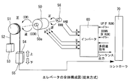
- FIG. 5 shows a configuration example of a conventional elevator using an inverter, a motor, and a load sensor.
- reference numeral 50 denotes an elevator driving motor, and a sheave 51 is fixed to a rotating shaft 50 a of the motor 50.
- a main rope 52 is wound around the sheave 51, a counter weight 53 is fixed to one end of the main rope 52, and an elevator car 54 is fixed to the other end.
- a load sensor 55 is provided at the lower end of the car 54.
- 56 is an encoder that is attached to the rotation shaft 50a of the motor 50 and detects the rotation speed and the rotation direction.
- the inverter 60 receives each detection information of the rotation speed and the rotation direction of the encoder 56, converts the power of an unillustrated input power supply or emergency power supply such as a UPS or a battery into a predetermined voltage, and outputs the U phase and V of the motor 50.
- the rotation of the motor 50 is controlled by applying to the phase and the W phase.
- a forward rotation operation command (UP (F RUN)
- a reverse rotation operation command (DOWN (R RUN)
- a multistage speed command and the like are transmitted from the controller 70 to the inverter 60, and the load from the load sensor 55 is transmitted to the controller 70.
- Information, various sequence outputs from the inverter 60, and the like are input.
- FIG. 6 shows a configuration of a brake device that is disclosed in Patent Document 3 and includes two sets of electromagnetic brakes (brakes 31 and 32).
- a main rope 25 is wound around a sheave 23 of the hoisting machine 21.
- a car 26 and a counterweight 27 are suspended on the main rope 25.
- the sheave 23 is directly connected to the electric motor 22 via a rotating shaft 24, and a brake wheel 30 is fixed to the rotating shaft 24.
- the brake control means (not shown) is released to deenergize the brake coils 31b and 32b, and the brake shoes 31a and 32a are pressed by springs (not shown) respectively to the brake wheel 30.
- the rotary shaft 24 is stopped by pressing.
- the brake control means (not shown) is closed to energize the brake coils 31b and 32b, attract the plungers 31c and 32c, and push the brake shoes 31a and 32a against the spring.
- the brake wheel 30 is released by retreating, and the electric motor 22 is driven to rotate.
- the speed control system of the motor in this invention utilizes the speed control system of patent document 4, for example.
- the present invention solves the above-mentioned problems, and its purpose is to determine a light load direction without using a load sensor or a torque sensor when a power failure occurs, and to move a car to the floor in the light load direction. It is an object of the present invention to provide an elevator car movement control apparatus and method capable of suppressing the power consumption of a UPS and a battery at the time of occurrence.
- An elevator car movement control device for solving the above-mentioned problem is provided.
- a main rope having a counterweight fixed and an elevator car fixed to the other end; a brake for stopping rotation of the rotating shaft of the motor; an encoder for detecting the rotational speed and direction of the motor; a speed command value; It has a speed control system that obtains a torque command value from a calculation result of a speed control amplifier that performs proportional integral calculation of a deviation of the speed detection value, and controls the motor in a variable speed including a zero speed region according to the torque command value.
- a control unit which converts the power of the input power source or emergency power source and supplies the motor to the motor, and the inverter operation
- a controller for communicating Nsu signals, a car movement control device for an elevator provided with,
- the controller is A function of performing control to switch the input of the inverter to an emergency power supply during a power failure of the input power supply, a function of controlling the open / close state of the brake, and a function of transmitting a multi-speed command sequence signal to the inverter;
- the control unit of the inverter The function of performing zero speed control of the speed control system in the brake open state at the time of a power failure of the input power supply, and calculating the torque command value of the speed control system when the zero speed control is performed, and calculating the calculated torque
- a light load direction detector for detecting a light load direction of the motor determined by a weight balance of the counterweight and the elevator car among the rotation directions of the motor detected by the encoder based on the polarity of the command value; After the light load direction is
- an elevator driving motor a sheave fixed to a rotating shaft of the motor, a coil weight is wound around the sheave, and a counterweight is fixed to one end.
- a main rope having an elevator car fixed to the other end, a brake for stopping the rotation of the rotating shaft of the motor, an encoder for detecting the rotational speed and direction of the motor, and a deviation between the speed command value and the detected speed value
- a control unit having a speed control system that obtains a torque command value from a calculation result of a speed control amplifier that performs proportional integral calculation, and controls the motor in a variable speed including a zero speed region according to the torque command value; Communication of sequence signals related to the operation of the inverter between the inverter that converts the power of the input power supply or emergency power supply and supplies it to the motor Cormorants a controller, a car movement control method for an elevator in an apparatus equipped with, The controller switching the input of the inverter to an emergency power supply during a power failure of the
- the relationship between the weight of the counter weight and the elevator car is, for example, when the counter weight weight is greater than the car weight, the direction rotating toward the counter weight side is the light load direction
- the direction of rotation toward the car side is the light load direction.
- a load torque is generated that keeps the car stopped without rotating in the light load direction.
- the polarity of the torque command value of the speed control system obtained by calculation at this time corresponds to the light load direction. Therefore, the light load direction can be easily detected based on the polarity of the torque command value without using a load sensor, a torque sensor, or the like.
- the light load direction is detected on the inverter side, and the elevator car movement direction is controlled on the inverter side regardless of the controller movement direction command, so the controller's forward rotation operation command (UP (F RUN)) or reverse rotation
- UP forward rotation operation command
- DOWN reverse rotation
- load sensors and torque sensors are not required, it is possible to prevent the risk of increased power consumption due to movement in the heavy load direction due to erroneous detection of signals from these sensors, and the risk that the car will stop halfway and be trapped between floors. it can.
- the direction of heavy load due to erroneous signal transmission from the controller to the inverter side It is possible to prevent an increase in power consumption due to the movement of the car and a risk that the car stops halfway and becomes trapped between floors.
- the whole elevator block diagram in the example of embodiment of this invention The connection structure of the input power supply in the example of embodiment of this invention, an emergency power supply, and an inverter is represented, (a) is a block diagram, (b) is a signal waveform diagram of each part of (a).
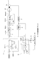
- the block diagram which shows an example of the motor speed control system of the control part of an inverter in the embodiment of this invention.
- FIG. 1 shows the overall configuration of the elevator of this embodiment example
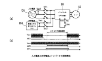
- FIG. 2 shows the connection configuration of the input power source, emergency power source, inverter, and motor in this embodiment example.
- the motor 50, the rotating shaft 50a, the sheave 51, the main rope 52, the counter weight 53, the car 54, and the encoder 56 are configured in the same way as in FIG. 5, but in this embodiment, the load sensor of FIG. 55 is not provided.
- the inverter 80 includes, for example, a power conversion unit in which switching elements are connected in a three-phase bridge, a motor speed control system (speed control block) illustrated in FIG. 3 and a polarity of a torque command value of the speed control system, which will be described later. And a control unit having a light load direction detection unit for detecting 50 light load directions.
- the inverter 80 receives the detection information (A, B) of the rotation speed and rotation direction of the encoder 56, and supplies the power of the input power supply 100 in FIG. 2A or the emergency power supply 110 such as a UPS or a battery to a predetermined value.
- the voltage is converted and applied to the U phase, V phase, and W phase of the motor 50 to control the rotation of the motor 50.
- 90 is a controller that communicates sequence signals related to inverter operation with the inverter 80.
- the sequence signal transmitted from the controller 90 to the inverter 80 is a command (normal / UPS) for switching the operation of the normal input power supply 100 and the emergency power supply 110 as shown in the upper part of FIG. (F RUN)), reverse operation command (DOWN (R RUN)), multi-speed command such as zero speed, high speed, low speed, creep speed and the like are included.
- a command normal / UPS
- DOWN reverse operation command
- multi-speed command such as zero speed, high speed, low speed, creep speed and the like are included.
- the sequence signal transmitted from the inverter 80 to the controller 90 includes a brake opening command, a signal indicating an operation state, a signal notifying the detected light load direction, and a load direction detection state as shown in the lower part of FIG. Includes signal to indicate.
- the brake device of FIG. 6 is disposed as a brake that mechanically stops the rotating shaft 50a between the motor 50 and the sheave 51 when the elevator stops.
- FIG. 2A shows a connection configuration in which the input of the inverter 80 is switched to the input power source 100 side or the emergency power source 110 side by the magnetic contactors MC1 and MC2.
- FIG. 2B shows signals of the respective parts in FIG. 2A
- Vac1 shows the interphase voltage of the input power supply 100
- Vac2 shows the output voltage of the emergency power supply 110
- SW1 shows the controller 90 when the input power supply 100 fails.
- the signal of the switch (SW1) that is turned on (closed) by the operation switching signal from, and MC1 of the magnetic contactor (MC1) that is turned on (closed) when the input power supply 100 is normal and turned off (opened) when a power failure occurs MC2 indicates a signal of the magnetic contactor (MC2) that is turned off (opened) when the input power supply 100 is normal and turned on (closed) when a power failure occurs. Therefore, the period during which the magnetic contactor MC2 is on (closed) corresponds to the operation period (UPS operation mode) of the emergency power supply 110.
- the emergency power supply 110 is not limited to a single-phase UPS or a battery, and a three-phase UPS may be used.
- FIG. 3 shows a speed control block disclosed in FIG.
- the motor 50 (PM motor) is driven at a variable speed by the output (frequency and voltage controlled output) of the power converter 80a of the inverter 80.
- the output control of the power converter 80a performs proportional integral (PI) calculation by the speed control amplifier 3 on the deviation between the speed command and the motor speed detection signal obtained by the encoder 56, the phase detector 8, and the speed detector 9.
- PI proportional integral
- This calculation result is limited by the torque limiter 4, converted into a current command corresponding to the torque command by the current command calculator 5, and the current control amplifier 6 performs proportional integral calculation on the deviation between the current command and the motor current detection signal.
- the output of the power converter 80a is controlled by this calculation result.
- the motor speed is detected from the pulse output of the encoder 56 with the phase detector 8 detecting the rotor rotational position of the motor as a phase (position), and the speed detector 9 detects the speed from the time change of this rotational position.
- the holding circuit 10 switches the speed between zero speed control and normal operation with a holding switch, and when the motor speed control state is in the normal operation speed region, the motor rotor position detection signal is buffered (Z ⁇ 1 ). In this case, the control signal is held for one control cycle, and if it is in the zero speed region, the position signal before the zero speed region is maintained.
- the position compensation amplifier 11 obtains a position compensation torque signal obtained by amplifying the deviation between the rotor position detection signal of the motor and the holding signal of the holding circuit 10 with a fixed gain, and this position compensation torque signal becomes the output of the speed control amplifier 3. Add to torque command. During normal operation, the output torque of the position control does not change by updating the buffer (Z ⁇ 1 ) of the holding circuit 10.
- the integral buffer (Z ⁇ 1 ) of the speed control amplifier 3 is reset when the position compensation amplifier 11 generates a position compensation torque signal, and shifts from the zero speed to the normal operation.
- the position compensation torque signal before transition is added to the integration buffer to prevent sudden torque change during transition.
- the low-pass filter 13 receives the position deviation signal at point A to be an input signal of the position compensation amplifier 11, and removes vibration components included in the position deviation signal by averaging processing.
- the load torque establishment determination unit 14 monitors whether the positional deviation signal that has passed through the low-pass filter 13 is stable, determines that the load torque has been established when stable, and switches the holding circuit 10 to the normal operation side. .
- the speed control performance during zero speed control can be improved, and even when the load sensor 55 of FIG. 5 is not provided, the necessary torque can be output, for example, for 100 ms after the brake is released, and the car 54 The fluctuation of the position of the can be suppressed.
- the light load direction detection unit provided in the control unit of the inverter 80 calculates a torque command value when the zero speed control is performed in the speed control block of FIG. 3 (torque limiter 4 of FIG. 3). Output), the light load direction of the motor determined by the weight balance of the counter weight 53 and the elevator car 54 among the rotation directions of the motor detected by the encoder 56 based on the polarity of the calculated torque command value. It is to detect.
- sequence output in FIG. 4 is a sequence signal output from the inverter 80 in FIG. 1 to the controller 90.
- Signal names in FIG. 4 are signals that are processed inside the inverter 80, and include a forward rotation command, a reverse rotation command, a multi-speed command, a speed command, and a torque command.
- the controller 90 sets the speed command value of the motor 50 to zero.
- the internal: multi-speed command in FIG. 4 becomes “zero speed”.
- the brake opening command is turned ON and the brake is opened. That is, a signal for opening the brake is output from the inverter 80 to the controller 90, and the controller 90 performs control to open the brake.
- the car 54 moves in the descending direction with its own weight alone (rotates in the reverse rotation (CCW) direction in the figure).
- the polarity of the torque command value is the forward (CW) direction of the motor 50. As a result, the motor speed becomes zero, and the car 54 stops.
- ⁇ Timing (6)> When a certain time (period (5)) has elapsed, the sequence output: the brake open command is turned OFF and the brake is closed. That is, a signal for closing the brake is output from the inverter 80 to the controller 90, and the controller 90 performs control to close the brake.
- ⁇ Timing (9)> The rotation direction of the motor 50 is determined from the light load direction measured at the timing (7) after the standby time (period (8)) has elapsed, and either the internal forward rotation command or the internal reverse rotation command in FIG.
- FIG. 4 shows an example in which the light load direction is on the counter weight 53 side, and the inside: forward rotation command is ON.
- This internal: forward rotation command may not match the sequence input: forward rotation operation command (or reverse rotation operation command) turned on at timing (2).
- sequence output in FIG. 4 the operation state is turned ON again, the light load direction detection is completed, and each signal informing the controller 90 of the light load direction (sequence output in FIG. 4: light load direction detection state, sequence Output: Light load direction).
- the controller 90 changes the sequence input to the low speed: multi-speed command.
- the multistage speed command in the inverter is switched from the zero speed to the low speed command, and the operation of the inverter 80 is started.
- the speed command changes from 0.
- the sequence output the brake opening command is turned ON at a time between the timing (9) and the timing (10), and the brake is controlled to be in the open state at the timing (10).
- ⁇ Timing (11)> When the car 54 approaches the destination floor, the controller 90 changes the creep input, the sequence input to the zero speed: multi-speed command. When zero speed is reached, the internal: forward rotation command or the internal: reverse rotation command (in this example, the internal forward rotation command) in FIG. 4 is turned OFF, the inverter 80 is stopped, the sequence output: the brake open command is turned OFF, and the brake is closed. Control. At this time, the car 54 reaches the destination floor and stops.
- the period from timing (3) to (7) is a load direction measurement operation period by speed command 0, the period from timing (4) to (6) is a light load direction detection period, and timing (9) to The period of (12) is a light load direction operation (forward rotation in this example) based on a multistage speed command from the controller 90.
- the elevator car 54 can be moved to the floor in the light load direction when a power failure occurs.
Abstract
Description
・センサ設置のコストがアップする。またセンサ設置用スペースを要する。
・コントローラの操作遅れ、コントローラの外乱ノイズによる正転運転指令(UP(F RUN))もしくは逆転運転指令(DOWN(R RUN))の誤送信、荷重センサ55からの検出値の外乱ノイズによる誤検出などが原因で、重負荷方向への移動となる場合があり、この場合UPSやバッテリの消費電力量が大きくなり、かごが途中停止し階間で閉じ込められるリスクが高まる。
前記コントローラは、
前記入力電源の停電時に、前記インバータの入力を非常電源に切り替える制御を行う機能と、前記ブレーキの開閉状態を制御する機能と、前記インバータへ多段速指令シーケンス信号を送信する機能とを備え、
前記インバータの制御部は、
前記入力電源の停電時に、前記ブレーキの開状態にて、前記速度制御系を零速度制御する機能と、前記零速度制御実施時の前記速度制御系のトルク指令値を演算し、該演算したトルク指令値の極性に基づいて、前記エンコーダにより検出されたモータの回転方向のうち、前記カウンタウェイトとエレベータのかごの重量バランスで決まるモータの軽負荷方向を検出する軽負荷方向検出部と、前記軽負荷方向検出部により軽負荷方向が検出された後に、前記ブレーキの開状態にて、前記検出された軽負荷方向のモータの回転方向および前記コントローラからの多段速指令シーケンス信号に従って速度指令値を演算し、演算した速度指令値を前記速度制御系の速度指令値として速度制御系を制御する機能と、を備えたことを特徴としている。
前記コントローラが、前記入力電源の停電時に、前記インバータの入力を非常電源に切り替えるステップと、前記コントローラが、前記インバータへ零速の多段速指令シーケンス信号を送信するステップと、前記コントローラが、前記ブレーキを開状態に制御するステップと、
前記インバータの制御部が、前記入力電源の停電時に、前記ブレーキの開状態にて、前記速度制御系を零速度制御するステップと、
前記インバータの制御部の軽負荷方向検出部が、前記零速度制御実施時の前記速度制御系のトルク指令値を演算し、該演算したトルク指令値の極性に基づいて、前記エンコーダにより検出されたモータの回転方向のうち、前記カウンタウェイトとエレベータのかごの重量バランスで決まるモータの軽負荷方向を検出する軽負荷方向検出ステップと、
前記コントローラが、前記軽負荷方向検出ステップによって前記モータの軽負荷方向が検出されたときに、インバータへ送信する多段速指令シーケンス信号を零速以外に設定するステップと、
前記インバータの制御部が、前記軽負荷方向検出ステップにより軽負荷方向が検出された後に、前記ブレーキの開状態にて、前記検出された軽負荷方向のモータの回転方向および前記コントローラからの多段速指令シーケンス信号に従って速度指令値を演算し、演算した速度指令値を前記速度制御系の速度指令値として速度制御系を制御するステップと、を備えたことを特徴としている。
図2の入力電源100に停電が発生する。図4のシーケンス入力:通常/UPSがONとなりUPS運転モードとなる。これにより、図2のMC1が開、MC2が閉となり、UPS(非常電源110)からインバータ80へ給電される(コントローラ90が行う、非常電源に切り替える制御)。またここでコントローラ90はモータ50の速度指令値=0とする。これにより、図4の内部:多段速指令は「零速」となる。
コントローラ90より、正転運転指令か逆転運転指令いずれかがONとなる。
インバータ80は前記タイミング(2)の指令を受け、内部の運転指令(正転指令又は逆転指令)がONとなり、速度指令値=0での運転開始となる。モータの速度制御では、図3の制御ブロックを用いる。またシーケンス出力:運転状態がONとなる。
図4のシーケンス出力:ブレーキ開指令をONとして、ブレーキ開とする。すなわち、インバータ80からコントローラ90へブレーキ開とする信号を出力し、コントローラ90がブレーキを開く制御を行う。
速度指令値=0で、一定時間の間、図4のシーケンス出力:ブレーキ開指令をONとして、ブレーキ開状態を保持する。この(5)の期間中に図3の制御ブロックによって演算されるトルク指令値を制御部内の図示省略のメモリなどに記録する。
一定時間(期間(5))が経過したら、シーケンス出力:ブレーキ開指令をOFFとして、ブレーキ閉とする。すなわち、インバータ80からコントローラ90へブレーキ閉とする信号を出力し、コントローラ90がブレーキを閉じる制御を行う。
前記期間(5)で記録したトルク指令値の極性より、軽負荷方向を決定する。また、タイミング(6)でブレーキ閉としているため、ここで一旦インバータ80の運転を停止する。さらに、この時点でシーケンス出力:運転状態はOFFとなる。
タイミング(7)の後、一定時間ブレーキ閉状態を保持する待機時間を設け、待機を実施する。
前記待機時間(期間(8))経過後にタイミング(7)で測定した軽負荷方向からモータ50の回転方向を決め、図4の内部正転指令、内部逆転指令いずれかをONとする。
コントローラ90は低速へシーケンス入力:多段速指令を変化させる。これを受けて、インバータ内部の多段速指令が零速から低速指令に切り替わり、インバータ80の運転を開始する。図4の内部:速度指令は0から変化する。内部:速度指令は、前記インバータ内部の低速指令とタイミング(9)で決めたモータ50の回転方向に基づいて演算する。図4では、内部:トルク指令の極性が負(モータ50の逆転(CCW)方向)であるので、内部:速度指令の極性は正(モータ50の正転(CW)方向)となっている。
かご54が目的階に近づいたところで、コントローラ90はクリープ速度、零速へシーケンス入力:多段速指令を変化させる。そして零速になったら図4の内部:正転指令または内部:逆転指令(この例では内部正転指令)をOFFさせて、インバータ80を停止し、シーケンス出力:ブレーキ開指令をOFFとしてブレーキ閉制御する。この時、かご54は目的階に到達し停止している。
インバータ80の停止後ブレーキは閉状態となっている。
インバータ80の停止を受けて、図4のシーケンス出力:運転状態をOFFとする。
コントローラ90からの運転指令(図4のシーケンス入力:(正転/逆転運転指令))をOFFとする。
図4のシーケンス入力:通常/UPSをOFFとすることで、インバータ80への給電がUPS(非常電源110)から入力電源100へ切り替わり(MC1がON、MC2がOFFし)、停電運転動作(UPS運転モード)完了とする。
Claims (2)
- エレベータ駆動用のモータと、該モータの回転軸に固設されたシーブと、該シーブに巻き掛けられ、一端にカウンタウェイトが固定され他端にエレベータのかごが固定された主ロープと、前記モータの回転軸の回転を停止させるブレーキと、前記モータの回転速度および回転方向を検出するエンコーダと、
速度指令値および速度検出値の偏差を比例積分演算する速度制御アンプの演算結果によりトルク指令値を求め、該トルク指令値に応じて、前記モータを零速度領域を含めて可変速制御する速度制御系を有した制御部を備え、入力電源又は非常電源の電力を変換して前記モータに供給するインバータと、
前記インバータとの間でインバータの運転に関するシーケンス信号の通信を行うコントローラと、を備えたエレベータのかご移動制御装置であって、
前記コントローラは、
前記入力電源の停電時に、前記インバータの入力を非常電源に切り替える制御を行う機能と、前記ブレーキの開閉状態を制御する機能と、前記インバータへ多段速指令シーケンス信号を送信する機能とを備え、
前記インバータの制御部は、
前記入力電源の停電時に、前記ブレーキの開状態にて、前記速度制御系を零速度制御する機能と、
前記零速度制御実施時の前記速度制御系のトルク指令値を演算し、該演算したトルク指令値の極性に基づいて、前記エンコーダにより検出されたモータの回転方向のうち、前記カウンタウェイトとエレベータのかごの重量バランスで決まるモータの軽負荷方向を検出する軽負荷方向検出部と、
前記軽負荷方向検出部により軽負荷方向が検出された後に、前記ブレーキの開状態にて、前記検出された軽負荷方向のモータの回転方向および前記コントローラからの多段速指令シーケンス信号に従って速度指令値を演算し、演算した速度指令値を前記速度制御系の速度指令値として速度制御系を制御する機能と、を備えたエレベータのかご移動制御装置。 - エレベータ駆動用のモータと、該モータの回転軸に固設されたシーブと、該シーブに巻き掛けられ、一端にカウンタウェイトが固定され他端にエレベータのかごが固定された主ロープと、前記モータの回転軸の回転を停止させるブレーキと、前記モータの回転速度および回転方向を検出するエンコーダと、
速度指令値および速度検出値の偏差を比例積分演算する速度制御アンプの演算結果によりトルク指令値を求め、該トルク指令値に応じて、前記モータを零速度領域を含めて可変速制御する速度制御系を有した制御部を備え、入力電源又は非常電源の電力を変換して前記モータに供給するインバータと、
前記インバータとの間でインバータの運転に関するシーケンス信号の通信を行うコントローラと、を備えた装置におけるエレベータのかご移動制御方法であって、
前記コントローラが、前記入力電源の停電時に、前記インバータの入力を非常電源に切り替えるステップと、
前記コントローラが、前記インバータへ零速の多段速指令シーケンス信号を送信するステップと、
前記コントローラが、前記ブレーキを開状態に制御するステップと、
前記インバータの制御部が、前記入力電源の停電時に、前記ブレーキの開状態にて、前記速度制御系を零速度制御するステップと、
前記インバータの制御部の軽負荷方向検出部が、前記零速度制御実施時の前記速度制御系のトルク指令値を演算し、該演算したトルク指令値の極性に基づいて、前記エンコーダにより検出されたモータの回転方向のうち、前記カウンタウェイトとエレベータのかごの重量バランスで決まるモータの軽負荷方向を検出する軽負荷方向検出ステップと、
前記コントローラが、前記軽負荷方向検出ステップによって前記モータの軽負荷方向が検出されたときに、インバータへ送信する多段速指令シーケンス信号を零速以外に設定するステップと、
前記インバータの制御部が、前記軽負荷方向検出ステップにより軽負荷方向が検出された後に、前記ブレーキの開状態にて、前記検出された軽負荷方向のモータの回転方向および前記コントローラからの多段速指令シーケンス信号に従って速度指令値を演算し、演算した速度指令値を前記速度制御系の速度指令値として速度制御系を制御するステップと、を備えたエレベータのかご移動制御方法。
Priority Applications (3)
| Application Number | Priority Date | Filing Date | Title |
|---|---|---|---|
| RU2016141606A RU2655257C1 (ru) | 2014-05-30 | 2015-05-20 | Устройство и способ управления движением кабины лифта |
| CN201580028738.1A CN106414298B (zh) | 2014-05-30 | 2015-05-20 | 电梯轿厢移动控制装置和轿厢移动控制方法 |
| EP15799380.9A EP3138802A4 (en) | 2014-05-30 | 2015-05-20 | Elevator car movement control device and car movement control method |
Applications Claiming Priority (2)
| Application Number | Priority Date | Filing Date | Title |
|---|---|---|---|
| JP2014111822A JP6237474B2 (ja) | 2014-05-30 | 2014-05-30 | エレベータのかご移動制御装置およびかご移動制御方法 |
| JP2014-111822 | 2014-05-30 |
Publications (1)
| Publication Number | Publication Date |
|---|---|
| WO2015182446A1 true WO2015182446A1 (ja) | 2015-12-03 |
Family
ID=54698783
Family Applications (1)
| Application Number | Title | Priority Date | Filing Date |
|---|---|---|---|
| PCT/JP2015/064415 WO2015182446A1 (ja) | 2014-05-30 | 2015-05-20 | エレベータのかご移動制御装置およびかご移動制御方法 |
Country Status (5)
| Country | Link |
|---|---|
| EP (1) | EP3138802A4 (ja) |
| JP (1) | JP6237474B2 (ja) |
| CN (1) | CN106414298B (ja) |
| RU (1) | RU2655257C1 (ja) |
| WO (1) | WO2015182446A1 (ja) |
Cited By (3)
| Publication number | Priority date | Publication date | Assignee | Title |
|---|---|---|---|---|
| CN112154115A (zh) * | 2018-05-09 | 2020-12-29 | 三菱电机株式会社 | 电梯装置和紧急停止检查装置的试验方法 |
| US11319188B2 (en) | 2017-03-06 | 2022-05-03 | Tk Elevator Innovation And Operations Gmbh | Drive arrangement comprising a moveable rail segment |
| US20230022982A1 (en) * | 2019-12-31 | 2023-01-26 | Inventio Ag | Method for moving an elevator car of an elevator in order to evacuate passengers, and brake opening device for moving an elevator car of an elevator |
Families Citing this family (3)
| Publication number | Priority date | Publication date | Assignee | Title |
|---|---|---|---|---|
| JP6835256B2 (ja) * | 2017-12-08 | 2021-02-24 | 三菱電機株式会社 | エレベータの制御装置 |
| KR102374810B1 (ko) * | 2018-05-30 | 2022-03-15 | 엘에스일렉트릭(주) | 엘리베이터 시스템의 브레이크 제어방법 |
| TWI792675B (zh) * | 2021-11-12 | 2023-02-11 | 台達電子工業股份有限公司 | 升降系統之干擾轉矩估測與補償方法 |
Citations (6)
| Publication number | Priority date | Publication date | Assignee | Title |
|---|---|---|---|---|
| JPS5334245A (en) * | 1976-09-09 | 1978-03-30 | Fujitec Co Ltd | Emergency elevator operating device |
| JPS56117974A (en) * | 1980-02-20 | 1981-09-16 | Mitsubishi Electric Corp | Driving device in case of emergency of elevator |
| JPS60131085A (ja) * | 1983-12-16 | 1985-07-12 | Mitsubishi Electric Corp | 交流エレベ−タの非常時運転装置 |
| JPH03243575A (ja) * | 1990-02-22 | 1991-10-30 | Mitsubishi Electric Corp | エレベータの速度制御装置 |
| JPH06127852A (ja) * | 1992-10-20 | 1994-05-10 | Toyo Electric Mfg Co Ltd | エレベータの起動制御方法 |
| JP5266799B2 (ja) * | 2008-03-05 | 2013-08-21 | 株式会社明電舎 | モータの可変速制御装置 |
Family Cites Families (7)
| Publication number | Priority date | Publication date | Assignee | Title |
|---|---|---|---|---|
| JPS60262783A (ja) * | 1984-06-12 | 1985-12-26 | 三菱電機株式会社 | 交流エレベ−タの停電時自動着床装置 |
| US7350626B2 (en) * | 2004-10-20 | 2008-04-01 | Otis Elevator Company | Power-on-reset of elevator controllers |
| ES2365921T3 (es) * | 2005-01-11 | 2011-10-13 | Otis Elevator Company | Procedimiento para realizar una operación de rescate de un ascensor. |
| KR100903661B1 (ko) * | 2007-08-08 | 2009-06-18 | 오티스 엘리베이터 컴파니 | 엘리베이터 구조 작업을 수행하는 방법 |
| CN103517863B (zh) * | 2011-12-21 | 2015-10-14 | 三菱电机株式会社 | 电梯装置及其控制方法 |
| CN103010875B (zh) * | 2012-12-19 | 2014-07-02 | 上海电机学院 | 电梯控制系统及电梯控制方法 |
| CN203127938U (zh) * | 2013-03-22 | 2013-08-14 | 乐山师范学院 | 电梯防空停控制系统 |
-
2014
- 2014-05-30 JP JP2014111822A patent/JP6237474B2/ja not_active Expired - Fee Related
-
2015
- 2015-05-20 RU RU2016141606A patent/RU2655257C1/ru active
- 2015-05-20 WO PCT/JP2015/064415 patent/WO2015182446A1/ja active Application Filing
- 2015-05-20 EP EP15799380.9A patent/EP3138802A4/en not_active Withdrawn
- 2015-05-20 CN CN201580028738.1A patent/CN106414298B/zh active Active
Patent Citations (6)
| Publication number | Priority date | Publication date | Assignee | Title |
|---|---|---|---|---|
| JPS5334245A (en) * | 1976-09-09 | 1978-03-30 | Fujitec Co Ltd | Emergency elevator operating device |
| JPS56117974A (en) * | 1980-02-20 | 1981-09-16 | Mitsubishi Electric Corp | Driving device in case of emergency of elevator |
| JPS60131085A (ja) * | 1983-12-16 | 1985-07-12 | Mitsubishi Electric Corp | 交流エレベ−タの非常時運転装置 |
| JPH03243575A (ja) * | 1990-02-22 | 1991-10-30 | Mitsubishi Electric Corp | エレベータの速度制御装置 |
| JPH06127852A (ja) * | 1992-10-20 | 1994-05-10 | Toyo Electric Mfg Co Ltd | エレベータの起動制御方法 |
| JP5266799B2 (ja) * | 2008-03-05 | 2013-08-21 | 株式会社明電舎 | モータの可変速制御装置 |
Non-Patent Citations (1)
| Title |
|---|
| See also references of EP3138802A4 * |
Cited By (3)
| Publication number | Priority date | Publication date | Assignee | Title |
|---|---|---|---|---|
| US11319188B2 (en) | 2017-03-06 | 2022-05-03 | Tk Elevator Innovation And Operations Gmbh | Drive arrangement comprising a moveable rail segment |
| CN112154115A (zh) * | 2018-05-09 | 2020-12-29 | 三菱电机株式会社 | 电梯装置和紧急停止检查装置的试验方法 |
| US20230022982A1 (en) * | 2019-12-31 | 2023-01-26 | Inventio Ag | Method for moving an elevator car of an elevator in order to evacuate passengers, and brake opening device for moving an elevator car of an elevator |
Also Published As
| Publication number | Publication date |
|---|---|
| JP6237474B2 (ja) | 2017-11-29 |
| CN106414298B (zh) | 2019-03-08 |
| CN106414298A (zh) | 2017-02-15 |
| RU2655257C1 (ru) | 2018-05-24 |
| EP3138802A4 (en) | 2018-05-09 |
| JP2015224127A (ja) | 2015-12-14 |
| EP3138802A1 (en) | 2017-03-08 |
Similar Documents
| Publication | Publication Date | Title |
|---|---|---|
| WO2015182446A1 (ja) | エレベータのかご移動制御装置およびかご移動制御方法 | |
| KR100312771B1 (ko) | 엘리베이터의정전운전제어장치및방법 | |
| JP3338680B2 (ja) | 停電時のエレベータ救出運転制御方法 | |
| US8348020B2 (en) | Elevator control device with carrier frequency switch circuit | |
| CN108883890B (zh) | 用于控制平衡系统中的运动的方法和设备 | |
| JP2009154988A (ja) | エレベータの戸開走行防止システム | |
| JPH0780646B2 (ja) | エレベーターの制御装置 | |
| KR101657020B1 (ko) | 엘리베이터의 제어 장치 및 엘리베이터의 제어 방법 | |
| JP5476681B2 (ja) | 昇降システムのモータ制御装置 | |
| JP5111502B2 (ja) | エレベータ装置 | |
| JPWO2004076326A1 (ja) | エレベーター用調速器 | |
| JP6297942B2 (ja) | エレベータ制御装置 | |
| JP2010143692A (ja) | エレベータ装置 | |
| JPH0464995B2 (ja) | ||
| JP5746373B2 (ja) | エレベーターの制御装置およびその制御方法 | |
| JP2001309694A (ja) | エレベータ用永久磁石同期電動機の調整方法およびその装置 | |
| JP2009057186A (ja) | エレベーター制御方法 | |
| JP2000211829A (ja) | エレベ―タ制御装置 | |
| JP2000078878A (ja) | 永久磁石式同期モータの制御装置 | |
| JP2011195279A (ja) | エレベータの制御装置 | |
| JP2008162766A (ja) | エレベータ | |
| JP2006160441A (ja) | エレベータの制御装置 | |
| JP2012082060A (ja) | エレベータ制御装置 | |
| EP2842897A1 (en) | Method for measuring opening and closing delay time of an elevator brake | |
| JP2015016933A (ja) | エレベータの駆動制御装置 |
Legal Events
| Date | Code | Title | Description |
|---|---|---|---|
| 121 | Ep: the epo has been informed by wipo that ep was designated in this application |
Ref document number: 15799380 Country of ref document: EP Kind code of ref document: A1 |
|
| NENP | Non-entry into the national phase |
Ref country code: DE |
|
| REEP | Request for entry into the european phase |
Ref document number: 2015799380 Country of ref document: EP |
|
| WWE | Wipo information: entry into national phase |
Ref document number: 2015799380 Country of ref document: EP |
|
| ENP | Entry into the national phase |
Ref document number: 2016141606 Country of ref document: RU Kind code of ref document: A |