WO2015182202A1 - 車両管理システム - Google Patents
車両管理システム Download PDFInfo
- Publication number
- WO2015182202A1 WO2015182202A1 PCT/JP2015/056380 JP2015056380W WO2015182202A1 WO 2015182202 A1 WO2015182202 A1 WO 2015182202A1 JP 2015056380 W JP2015056380 W JP 2015056380W WO 2015182202 A1 WO2015182202 A1 WO 2015182202A1
- Authority
- WO
- WIPO (PCT)
- Prior art keywords
- travel
- section
- vehicle
- travel permission
- information
- Prior art date
- Legal status (The legal status is an assumption and is not a legal conclusion. Google has not performed a legal analysis and makes no representation as to the accuracy of the status listed.)
- Ceased
Links
Images




Classifications
-
- G—PHYSICS
- G05—CONTROLLING; REGULATING
- G05D—SYSTEMS FOR CONTROLLING OR REGULATING NON-ELECTRIC VARIABLES
- G05D1/00—Control of position, course, altitude or attitude of land, water, air or space vehicles, e.g. using automatic pilots
- G05D1/02—Control of position or course in two dimensions
- G05D1/021—Control of position or course in two dimensions specially adapted to land vehicles
- G05D1/0287—Control of position or course in two dimensions specially adapted to land vehicles involving a plurality of land vehicles, e.g. fleet or convoy travelling
- G05D1/0289—Control of position or course in two dimensions specially adapted to land vehicles involving a plurality of land vehicles, e.g. fleet or convoy travelling with means for avoiding collisions between vehicles
-
- G—PHYSICS
- G05—CONTROLLING; REGULATING
- G05D—SYSTEMS FOR CONTROLLING OR REGULATING NON-ELECTRIC VARIABLES
- G05D1/00—Control of position, course, altitude or attitude of land, water, air or space vehicles, e.g. using automatic pilots
- G05D1/02—Control of position or course in two dimensions
-
- G—PHYSICS
- G08—SIGNALLING
- G08G—TRAFFIC CONTROL SYSTEMS
- G08G1/00—Traffic control systems for road vehicles
Definitions
- the present invention relates to a vehicle management system that manages the traveling of a plurality of vehicles traveling along a predetermined traveling route.
- Patent Document 1 discloses that the current position of a vehicle is transmitted to the control station at a predetermined time interval or every predetermined distance movement. Instructions such as continuation of travel, deceleration, and stop are transmitted to each vehicle so that mutual interference does not occur due to the mutual relationship between vehicle positions. In addition, vehicles that are close to each other are wirelessly communicated with each other to exchange position information with each other and travel so as not to interfere with each other.
- the control station instructs each vehicle by wireless communication as a travel permission region in a region where the vehicle can travel without interfering with other vehicles according to the vehicle position.
- Each vehicle travels according to a given travel permission area, thereby preventing mutual interference.
- Patent Document 1 since communication is performed between the vehicle and the control station every predetermined time or every predetermined distance, communication frequently occurs in each vehicle. On the other hand, when long-distance communication is performed in a large area such as a mine, the communication band is generally narrowed due to the characteristics of wireless communication, and the amount of usable communication is limited. For this reason, in the vehicle control system with a high communication frequency as in Patent Document 1, there is a problem that it is not possible to simultaneously manage the traveling of a large number of vehicles.
- Patent Document 2 by setting a travel permission area for a vehicle, it is possible to prevent interference between the vehicles without performing communication within the travel permission area.
- this patent document 2 it is possible to reduce the update frequency and reduce the traffic by setting a large travel permission area to be given at one time.
- the travel permission area is set excessively long, the travel interval between the vehicles becomes large, and there is a problem that the operation density of the vehicle decreases. This problem leads to a decrease in production volume in the mine and is a very big problem.
- This invention was made in order to solve the said subject, and it aims at providing the vehicle management system which a several vehicle can drive
- the present invention divides a predetermined travel route as a plurality of sections, and manages a plurality of vehicles traveling along the travel route on the basis of the sections.
- a travel permission section setting unit that sets a part of the travel route as a travel permission section without overlapping each of the plurality of vehicles, section information regarding each section of the travel route, and
- a storage unit that stores predetermined traveling speed information for each section in the section information, and information on the travel permission section set by the travel permission section setting unit is transmitted to the vehicle that has set the travel permission section.
- a vehicle-mounted communication unit that is attached to the vehicle and receives information on the travel-permitted section that is transmitted by the communication unit, and the travel-permitted section setting unit includes the storage unit Based on the stored section information and the travel speed information, a travel permission section is set for a vehicle traveling in a predetermined section, and the travel permission section setting unit sets the number of sections ahead of the predetermined section as the predetermined section. It is set according to the traveling speed determined for the section.
- the present invention configured as described above is a section set as a travel permission section for a vehicle traveling in a predetermined section based on section information of each section on the travel route and travel speed information predetermined for each section.
- the number is set according to the traveling speed determined for the predetermined section. That is, by setting the number of sections as the travel permission section according to the travel speed of the predetermined section, it is possible to set a suitable travel permission section to such an extent that the travel intervals of the plurality of vehicles do not become too large. Therefore, since the travel intervals of the plurality of vehicles do not become too large, the communication amount related to the transmission of the information of the permitted travel section can be reduced, and the plurality of vehicles can travel without interference while maintaining the operation density of the plurality of vehicles. be able to.
- the travel permission section setting unit is configured so that a travel interval between a vehicle that sets the travel permission section and another vehicle that follows the vehicle is a predetermined distance.
- the travel permission section for each vehicle is set. Therefore, the present invention can manage the travel of each of these vehicles while maintaining the travel interval between the vehicle that sets the travel permission section and another vehicle that follows this vehicle as a predetermined distance. Therefore, mutual interference of these vehicles can be prevented, and each vehicle can be run without lowering the operation density of these vehicles by preventing the running intervals of these vehicles from becoming too large.
- the present invention is characterized in that, in the above configuration, the travel permission section setting unit sets the travel permission section so that a transit time of at least a part of the plurality of sections is constant. To do. Therefore, according to the present invention, the passage time of a part of the plurality of sections on the travel route can be made constant, and the traveling speed of the part of the section is determined. It is possible to maintain the vehicle interval of the other vehicles. Therefore, mutual interference of a plurality of vehicles can be prevented, and each vehicle can be run without lowering the operation density of these vehicles by preventing the running interval of these vehicles from becoming too large.
- the travel permission section setting unit is configured such that after a vehicle that sets the travel permission section passes through a predetermined point on the travel route, another vehicle following the vehicle The travel permission section is set so that the time interval until passing is constant. Therefore, the present invention can make the time interval from when a predetermined vehicle passes a predetermined point on the travel route to when another vehicle following this vehicle passes the predetermined point. Therefore, since the travel speed for each section on the travel route is determined, the travel intervals of a plurality of vehicles that pass a predetermined point on the travel route can be maintained. Therefore, mutual interference of a plurality of vehicles can be prevented, and each vehicle can be run without lowering the operation density of these vehicles by preventing the running interval of these vehicles from becoming too large.
- the present invention is characterized in that, in the above configuration, the traveling speed information is set for each section according to a change in a traveling direction, a slope, and a road surface state in each section on the traveling route.
- the traveling speed of each section changes depending on the travel direction change (for example, curve curvature), slope (for example, slope), and road surface condition (road surface conditions such as gravel roads and roads that have been compacted). Therefore, the present invention sets the travel speed for each section according to the change of the travel direction, the slope and the road surface condition in each section, thereby changing the topographical change of each section on the travel route.
- it is possible to set travel permission sections of a plurality of vehicles and it is possible to more appropriately secure the travel intervals of the plurality of vehicles. Therefore, the mutual interference of these several vehicles can be prevented more appropriately, and each vehicle can be made to travel without lowering the operation density.
- the present invention is the above configuration, wherein the vehicle is a dump truck, and includes a load state detection unit that detects a load state of the dump truck, and the travel permission section setting unit includes the section information and the travel speed information.
- the travel permission section is set according to the load state information of the dump truck detected by the load state detection unit.
- the actual traveling speed of a dump truck changes depending on the loading state (for example, the speed decreases due to the weight of the load when the load is loaded, and the weight of the dump truck increases according to the weight of the load. No speed reduction.)
- the present invention sets the travel permission section according to the load state information of the dump truck detected by the load state detection unit in addition to the section information on the travel route and the travel speed information in each section.
- the present invention by setting the number of sections as the travel permission section according to the travel speed of the predetermined section, it is possible to set a suitable travel permission section so that the travel intervals of the plurality of vehicles do not become too large. it can. Therefore, since the travel intervals of a plurality of vehicles do not become too large, the amount of communication related to the transmission of information on the permitted travel section can be reduced, and the plurality of vehicles can travel without interference while maintaining the operation density of the plurality of vehicles. Can do. Problems, configurations, and effects other than those described above will be clarified by the following description of embodiments.
- FIG. 1 It is a schematic diagram showing the composition of the vehicle management system concerning a 1st embodiment of the present invention. It is the figure which explained in full detail the conveyance path in FIG. It is a perspective view which shows the structure of the dump truck which is an example of the vehicle which carries out operation management by the said vehicle management system. It is a hardware block diagram of the said vehicle management system. It is a block diagram which shows the main functions of the traffic control server and dump terminal device of the said vehicle management system. It is a figure which shows the travel permission area setting process by the said vehicle management system, (a) is transmission of destination request information, (b) is reception of destination route information, (c) is transmission of area request information, and section information It is reception.
- an unmanned dump truck (corresponding to an unmanned vehicle) that transports earth and sand or ore loaded by a loader such as an excavator or a wheel loader in a mine and travels autonomously without boarding a driver
- a loader such as an excavator or a wheel loader in a mine and travels autonomously without boarding a driver
- a vehicle management system that connects a traffic control server that controls traffic to avoid unmanned dumping interference with a wireless communication line, interfering with multiple dump trucks while maintaining the required operation density with a particularly small amount of communication.
- FIG. 1 is a schematic diagram showing a configuration of a vehicle management system according to the first embodiment of the present invention.
- a vehicle management system 1 shown in FIG. 1 is a mine dump truck for transporting loads of earth and sand or ore loaded from excavators 10a and 10b for loading earth and ore in a quarry such as a mine.
- the unmanned dump trucks 20a and 20b, and the traffic control server 31 installed in the control center 30 near the quarry or a remote control station are connected to each other via a wireless communication line 40. It is a management system.
- the unmanned dump trucks 20a and 20b reciprocate between the excavators 10a and 10b and an unillustrated earthmoving site along a transportation path 60 set in advance in the mine, and transport the load.
- a plurality of radio base stations 41a to 41c are installed in the mine. Then, radio communication radio waves are transmitted and received via these radio base stations 41a to 41c.
- the excavators 10a and 10b and the unmanned dump trucks 20a and 20b are positions for receiving positioning radio waves from at least three navigation satellites 50a to 50c of the global navigation satellite system (GNSS) and acquiring the position of the own vehicle.
- a calculation device 29 (see FIG. 4) is provided.
- GNSS global Navigation Satellite System
- GPS Global Positioning System
- GLONASS Global Navigation Satellite System
- GALILEO Global Navigation Satellite System
- the excavator 10 a is an ultra-large hydraulic excavator, and includes a traveling body 11, a revolving body 12 that is turnable on the traveling body 11, a cab 13, and a front that is provided at the front center of the revolving body 12. And a work machine 14.
- the front work machine 14 includes a boom 15 provided so as to be movable up and down with respect to the revolving structure 12, an arm 16 provided rotatably at the tip of the boom 15, and a bucket 17 attached to the tip of the arm 16.
- An antenna 18 for connecting to the wireless communication line 40 is installed at a place with good visibility in the excavator 10 a, for example, at the top of the cab 13.
- FIG. 3 is a perspective view showing a configuration of an unmanned dump truck 20a that is operated and managed by the vehicle management system 1.
- the unmanned dump truck 20a has a frame 21 that forms a main body, a front wheel 22 and a rear wheel 23, and a hinge pin (not shown) provided at a rear portion of the frame 21 as a rotation center. And a pair of left and right hoist cylinders (not shown) that rotate the loading platform 24 in the vertical direction.
- the unmanned dump truck 20a is provided with an antenna 25 for connecting to the radio communication line 40 in a place with good visibility, for example, in front of the deck 280 attached to the upper side of the front wheels 22 and the rear wheels 23 of the unmanned dump truck 20a.
- the hoist cylinder of the unmanned dump truck 20a is provided with a pressure sensor (not shown) for detecting the load of the load loaded on the loading platform 24.
- the unmanned dump truck 20a is equipped with a dump terminal device 26 as an in-vehicle terminal device for autonomously traveling according to an instruction from the traffic control server 31.
- the traffic control server 31 is connected to an antenna 32 for connecting to the radio communication line 40, and communicates with each of the dump terminal devices 26 via the antenna 32 and the radio base stations 41a to 40c.
- FIG. 2 is a diagram detailing the conveyance path 60 in FIG. 1, and shows a configuration example of an open pit mine site where the unmanned dump truck 20a travels.
- An excavation site 61 by an excavator 10a is provided at the mine site.
- the excavator 10a loads the topsoil and ore dug at the excavation site 61 into the unmanned dump truck 20a. Therefore, the excavation site 61 includes a loading position.
- a release ground 62 where the topsoil is developed.
- the topsoil and the like transported from the excavation site 61 by the unmanned dump truck 20a are released at the earth release site 62 and developed in a layered or radial manner.
- a slaughterhouse 63 in which a crusher (not shown) for crushing the ore is installed at the mine site.
- the ore crushed by the crusher is transported to a freight car loading site or processing facility by a belt conveyor or the like.
- the unmanned dump truck 20 a is loaded with topsoil and ore at the excavation site 61.
- the unmanned dump truck 20a travels on the transport path 60 and transports the loaded topsoil and ore to the earth release sites 62 and 63.
- the unmanned dump truck 20a reciprocates between the excavation site 61 and the earth discharging field 62.
- the unmanned dump truck 20 a reciprocates between the excavation site 61 and the earth discharging field 63.
- the conveyance path 60 includes a conveyance path that connects the excavation site 61 and the earthing field 62 and a conveyance path 60 that connects the excavation site 61 and the earthing field 63. Further, a curve section 67 corresponding to the terrain of the mine is provided on the conveyance path 60.
- Each travel route 64 constitutes an up lane and a down lane.
- the unmanned dump truck 20a travels on the conveyance path 60 in the same way as a general road, for example, by right-hand traffic.
- the travel route 64 is given as a coordinate value set on the map.
- the same map information is stored in each of the traffic control server 31 and each of the unmanned dump trucks 20a to 20c. This map information includes a point on the map, that is, a node 65 and a coordinate value of this node 65.
- the travel route 64 is defined by being divided into a plurality of nodes 65 and sublinks 66 as sections connecting the adjacent nodes 65.
- FIG. 4 is a hardware configuration diagram of the vehicle management system 1.
- the traffic control server 31 includes a server-side control device 311, a server-side input device 312, a server-side display device 313, a server-side communication device 314, a communication bus 315, a master map information database (hereinafter referred to as “database”). 316) and travel permission section information DB 317.
- database master map information database
- the server-side control device 311 controls the operation of each component of the traffic control server 31, and stores a program executed by the traffic control server 31 in addition to a calculation / control device such as a CPU (Central Processing Unit). It is configured using hardware including a storage device such as a ROM (Read Only Memory) and an HDD (Hard Disk Drive), and a RAM (Random Access Memory) that is a work area when the CPU executes a program. Further, the server-side control device 311 may be configured using an integrated circuit (ASIC: application specific integrated circuit) for realizing a function executed by the traffic control server 31.
- ASIC application specific integrated circuit
- the server side input device 312 is composed of an input device such as a mouse or a keyboard, and functions as a user interface for displaying the status of the unmanned dump 20a and inputting manual instructions to the unattended dump 20a.
- the server-side display device 313 is composed of a liquid crystal monitor or the like, and functions as an interface that displays and provides information to an operator who operates the traffic control server 31.
- the server-side communication device 314 is a communication unit configured by a device that performs communication connection with a wired / wireless network.
- the server-side communication device 314 is connected to the antenna 32 via the wired communication line 33 and is connected to the radio base stations 41 a to 41 c via the radio communication line 40.
- the communication bus 315 includes each component of the traffic control server 31, that is, the server-side control device 311, the server-side input device 312, the server-side display device 313, the server-side communication device 314, the communication bus 315, the master map information DB 316, and the travel permission.
- Each of the section information DBs 317 is electrically connected to each other.
- the master map information DB 316 is configured using a storage device that stores information such as HDDs in a fixed manner, and the position information (coordinate values) of each node 65 on the transport path 60 and the sublink 66 that connects the nodes 65. And the map information (travel route information) defined by Here, the master map information DB 316 may include mining landform information and absolute coordinates (three-dimensional real coordinates calculated based on positioning radio waves) of each node 65. Each node 65 is given position identification information that uniquely identifies the node 65, that is, a node ID.
- the travel-permitted section information DB 317 is configured using a storage device that stores information such as HDDs in a fixed manner, and includes vehicle identification information that uniquely identifies each unmanned dump 20a, and a travel-permitted section assigned to each unmanned dump 20a. , Position information regarding the actual traveling speed at the current position of each unmanned dump truck 20a, section information regarding a section obtained by dividing the traveling route 64 into a plurality of speeds, and a speed limit determined in advance for each section ( Travel permission section information including speed limit information related to travel speed) is stored.
- the master map information DB 316 and the travel-permitted section information DB 317 include only a storage unit that stores the map information and the travel-permitted section information, and the server-side control device 311 performs update / search processing of the master map information DB 316 and the travel-permitted section information DB 317.
- the master map information DB 316 and the travel-permitted section information DB 317 may be equipped with an engine for performing information update / search processing.
- the unmanned dump truck 20a is an electrically driven dump truck.
- the vehicle control apparatus 27 that controls acceleration / deceleration and steering of the unmanned dump truck 20a in response to an instruction from the dump terminal apparatus 26, the outside world A sensor device 28 and a position detection device 29 are provided.
- the dump terminal device 26 is wirelessly connected to the traffic control server 31 via the wireless base stations 41a to 41c.
- the dump terminal device 26 includes a terminal-side control device 261, a terminal-side input device 262, a terminal-side display device 263, a terminal-side communication device 264, a communication bus 265, and a terminal-side map information DB 266.
- the terminal side control device 261, the terminal side input device 262, the terminal side display device 263, the terminal side communication device 264, the communication bus 265, and the terminal side map information DB 266 are respectively a server side control device 311, a server side input device 312, a server Since the configuration is the same as each of the side display device 313, the server side communication device 314, the communication bus 315, and the master map information DB 316, duplicate description is omitted.
- the terminal-side map information DB 266 stores the same map information as the map information stored in the master map information DB 316.
- the vehicle control device 27 includes a retarder brake 271, a service brake 272, a steering control device 273, and an acceleration control device 274.
- the vehicle control device 27 is electrically connected to the dump terminal device 26 and causes the unmanned dump truck 20-1 to autonomously travel in accordance with an instruction from the traffic control server 31.
- the retarder brake 271 is a brake used during normal braking.
- the retarder brake 271 is controlled by operating a motor constituting an electric drive engine as a generator, converting kinetic energy into electric energy to generate regenerative power, and applying this to a resistor to be consumed as heat energy. Get power.
- the service brake 272 is a brake used at the time of emergency braking, and is constituted by a mechanical brake. Frequent use of the service brake 272 results in wear of mechanical brake components such as brake pads and discs. Therefore, in the present embodiment, the retarder brake 271 and the service brake 272 are selectively used according to the degree of urgency.
- the steering control device 273 adjusts the steering angle of the unmanned dump truck 20a.
- the acceleration control device 274 adjusts acceleration and deceleration of the unmanned dump truck 20a.
- the external sensor device 28 is attached to laser radar sensors 281 and 282 attached to both sides of the deck 280 of the unmanned dump truck 20a, and to the front center portion below the deck 280 of the unmanned dump truck 20a. And a millimeter wave radar sensor 283.
- the laser radar sensors 281 and 282 detect the shoulder position of the travel route 64 on which the unmanned dump truck 20a travels.
- the millimeter wave radar sensor 283 detects an obstacle ahead of the unmanned dump truck 20a in the traveling direction.
- the detection results of the external sensor device 28 by the laser radar sensors 281 and 282 and the millimeter wave radar sensor 283 are output to the terminal-side control device 261 of the dump terminal device 26, and the traveling position so as not to leave the traveling route 64 at normal times. It is used for monitoring and acceleration / deceleration, and in emergency, it is used for braking operation necessary for emergency avoidance behavior.
- the means for detecting the shoulder of the traveling route 64 is not necessarily the laser radar sensors 281 and 282, and the shoulder may be detected by image processing using a camera.
- the camera is installed so as to look down at the side of the unmanned dump truck 20a.
- the means for detecting the obstacle ahead of the traveling direction is not necessarily the millimeter wave radar sensor 283, and may be detected by a stereo camera.
- the stereo camera is a plurality of cameras installed in front of the unmanned dump truck 20a.
- the millimeter wave radar sensor 283 may be installed further above the deck 280 shown in FIG. 3 so as to look down on the road surface.
- the position calculation device 29 calculates the current position (self position) of the host vehicle based on the positioning radio waves from the navigation satellites 50a to 50c.
- the calculated current position of the host vehicle is transmitted from the dump terminal device 26 to the traffic control server 31.
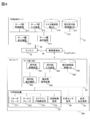
- FIG. 5 is a block diagram showing the main functions of the traffic control server 31 and the dump terminal device 26.
- the server-side control device 311 of the traffic control server 31 includes a vehicle allocation management unit 311a, a travel-permitted section setting unit 311b, a server-side communication control unit 311d, and a communication interface (hereinafter referred to as “communication I / F”). (Abbreviated) 311e.
- the vehicle allocation management unit 311a sets the destination of the unmanned dump truck 20a and refers to the map information stored in the master map information DB 316 to determine the travel route 64 from the current position to the destination.
- processing of the dispatch management unit 311a for example, when the unmanned dump truck 20a is in a parking lot, it is set for the purpose of the entrance of the loading area including the loading position. And the vehicle allocation management part 311a sets the driving
- the vehicle allocation management unit 311a may dynamically set the travel route 64 in accordance with the movement of the loading position when setting the travel route 64. Furthermore, when the unmanned dump truck 20a enters the loading position, the vehicle allocation management unit 311a sets one of the dumping grounds 62 and 63 as a destination depending on the content of the load, and a travel route to reach this destination 64 is set.
- the travel permission section setting unit 311b refers to the map information stored in the master map information DB 316 with respect to the unmanned dump 20a, and travels for each sublink 66 defined as between the nodes 65 on the determined travel route 64. Granting or canceling the permission, a section (partial section) including at least one or more sub-links 66 is set as a travel permission section that permits the unmanned dump truck 20a to travel, and travel in the set travel permission section The travel permission section information indicating the position in the route 64 is generated.
- the travel permission section setting unit 311b sets a partial section on the travel route 64 as a travel permission section for the plurality of unmanned dump trucks 20a to 20c without duplication with respect to the plurality of unmanned dump trucks 20a to 20c to be managed. To do.
- the travel permission section setting unit 311b updates the travel permission section information stored in the travel permission section information DB 317 by overwriting the newly generated travel permission section information.
- the travel permitted section information includes position information including the node ID of the front boundary point that is the frontmost node 65 of the travel permitted section and the node ID of the rear boundary point that is the rearmost node 65.
- the travel permission section setting unit 311b receives section request information for requesting setting of a new travel permission section from the dump terminal device 26, the travel permission section setting unit 311b performs a travel permission section setting process in response to reception of the section request information.
- the travel-permitted section setting unit 311b generates travel-permitted section information for the travel-permitted section when a new travel-permitted section is set. If the travel-permitted section information cannot be generated, a response indicating that travel is not permitted. Generate information.
- the server-side communication control unit 311d performs wireless communication control with the dump terminal device 26. Specifically, the server-side communication control unit 311d transmits the braking instruction information for instructing the braking of the unmanned dump truck 20a and the travel permission section information or the response information to the dump terminal device 26.
- the server-side communication control unit 311d receives, from the dump terminal device 26, section request information related to a travel section request from the unmanned dump 20a, unmanned dump position information indicating the position of the host vehicle calculated by the position calculation device 29 of the unmanned dump 20a, and The actual speed information of the unmanned dump 20a is received.
- the actual speed information may be configured as information indicating a speed (vector) including the traveling direction and speed (scalar amount) based on the change amount of the position information, or a vehicle body such as a gyro sensor mounted on the unmanned dump truck 20a. You may comprise as the information which combined the output calculated
- the communication I / F 311e is configured by hardware for communication connection with the server side communication device 314, such as a USB (Universal Serial Bus) standard connection terminal.
- USB Universal Serial Bus
- the terminal side control device 261 of the dump terminal device 26 includes an autonomous traveling control unit 261a, a terminal side communication control unit 261b, a communication I / F 261c, and a request information processing unit 261d.
- the autonomous travel control unit 261a acquires the current position of the host vehicle from the position calculation device 29, refers to the map information in the terminal-side map information DB 266, and causes the host vehicle to travel according to the travel permission section included in the travel permission section information. Control for the vehicle control device 27 is performed.
- the autonomous traveling control unit 261a determines the presence or absence of a front obstacle based on the detection result of the external sensor device 28, also determines the presence or absence of interference with the obstacle and collision avoidance operation, and brakes the unmanned dump truck 20a as necessary. Control.
- the autonomous traveling control unit 261a performs drive control on the vehicle control device 27 in accordance with an instruction from the traffic control server 31, performs a deceleration operation, a normal stop operation, or an emergency stop operation, and avoids interference between the unmanned dump trucks 20a to 20c. Travel control is performed as follows.
- the autonomous travel control unit 261a refers to the speed limit information stored in the terminal-side map information DB 266, and sets each sublink 66 on the travel route 64 for each sublink 66. Drive at an appropriate speed within.
- the terminal-side communication control unit 261b controls wireless communication performed with the traffic control server 31.
- the terminal-side communication control unit 261b transmits section request information and receives travel permission section information or response information and braking instruction information.
- the communication I / F 261c is a USB standard connection terminal or the like, and is configured by hardware for performing communication connection with the terminal-side communication device 264.
- the request information processing unit 261d determines whether the unmanned dump truck 20a has reached the point where the section request information is transmitted. When the request point is reached, section request information is generated and section request information is transmitted to the traffic control server 31 via the terminal-side communication control unit 261b.
- the vehicle allocation management unit 311a, the travel-permitted section setting unit 311b, and the server-side communication control unit 311d included in the traffic control server 31 are executed by the server-side control device 311 (hardware) shown in FIG. 4 by a program that realizes these functions. To be realized.
- the autonomous traveling control unit 261a, the terminal-side communication control unit 261b, and the request information processing unit 261d provided in the dump terminal device 26 have a terminal-side control device 261 (hardware) whose program realizing these functions is shown in FIG. Hardware).
- FIGS. 6A and 6B are diagrams showing a travel permission section setting process by the vehicle management system 1, where (a) is transmission of destination request information, (b) is reception of destination route information, and (c) is transmission of section request information. And reception of travel permission section information.
- the unmanned dump 20a In the state where the unmanned dump 20a has completed the loading of the topsoil and ore at the excavation site 61 or the state where the unloading at the earthing grounds 62 and 63 is completed, the unmanned dump 20a is as shown in FIG.
- Destination request information for requesting the destination of the unmanned dump truck 20a is transmitted to the traffic control server 31 of the control center 30.
- This destination request information is obtained from the current position detected by the position calculation device 29 based on the positioning radio waves from the navigation satellites 50a to 50c by the autonomous traveling control unit 261a mounted on the unmanned dump truck 20a.
- the travel position of 20a is determined and transmitted via the terminal-side communication control unit 261b, the communication I / F 261c, and the terminal-side communication device 264.
- the destination request information is transmitted from the terminal-side communication device 264 and then received from the antenna 32 of the control center 30 to the server-side communication device 314 via the radio base stations 41a to 41c.
- the vehicle allocation management unit 311a is unmanned in consideration of, for example, traveling conditions such as traveling position, traveling speed, traveling direction, and the like of the other plain dump trucks 20b and 20c other than the unmanned dump truck 20a corresponding to the sent destination request information.
- the destination 71 of the dump truck 20a (for example, corresponding to the excavation site 61, the earthing grounds 62, 63, etc. in FIG. 2) and the route 72 to the destination 71 are determined, and the determined destination is determined. Destination route information regarding the route 72 leading to is transmitted to the server-side communication control unit 311d. As shown in FIG.
- the server-side communication control unit 311d sets the received destination route information together with the vehicle identification information corresponding to the unmanned dump 20a that has determined the destination route information, the communication I / F 311e, It transmits via the server side communication apparatus 314 and the antenna 32.
- the transmitted destination route information is transmitted to the terminal side communication device 264 of the unmanned dump truck 20a corresponding to the vehicle identification information transmitted together with the destination route information via the radio base stations 40a to 40c.
- the data is output from the communication device 264 to the autonomous travel control unit 261a via the communication I / F 311e and the terminal side communication control unit 261b.
- the autonomous traveling control unit 261a transmits section request information for requesting a traveling permission section of the unmanned dump truck 20a.
- This section request information is transmitted from the terminal-side communication device 264 and sent from the antenna 32 of the control center 30 to the travel permission section setting unit 311b via the radio base stations 40a to 40c.
- the travel permission section setting unit 311b sets a travel permission section 73 based on the processing described later, and the travel permission section information indicating the position of the set travel permission section is stored on the server side. It transmits to the communication control part 311d.
- the server-side communication control unit 311d transmits the received travel permission section information from the antenna 32 together with the vehicle identification information corresponding to the unmanned dump truck 20a in which the travel permission section is set.
- the transmitted travel permit section information is received by the terminal side communication device 264 of the unmanned dump truck 20a corresponding to the vehicle identification information transmitted together with the travel permit section information and sent to the autonomous travel control unit 261a.
- the autonomous traveling control unit 261a permits traveling of the unmanned dump truck 20a over the traveling permitted section in the transmitted traveling permitted section information, controls the vehicle control device 27, and the sublink 66 in the traveling permitted section.
- the unmanned dump truck 20a starts to travel at a speed equal to or less than the speed limit set for each time.
- the travel permission section setting information regarding which sublink 66 on the travel route 64 is permitted to travel to which unmanned dump trucks 20a to 20c is stored in the master map information DB 316 of the traffic control server 31.
- the travel permission section setting unit 311b manages the travel permission section setting in response to the travel permission requests from the unmanned dump trucks 20a to 20c while referring to the travel permission section setting information stored in the master map information DB 316. Do.
- the unmanned dump trucks 20a to 20c store the travel permission section information received from the traffic control server 31 of the control center 30 in the terminal side map information DB 266, and the unmanned dump trucks 20a to 20c that have received the travel permission section information
- the autonomous traveling control unit 261a determines which node 65 can travel.
- the setting state of the travel permission section is set to correspond to the section ID set for each sublink 66 in the travel route 64, and the traffic control server 31 side has a memory section (not shown) of the travel permission section setting section 311b.
- Each unmanned dump truck 20a-20c side temporarily stores travel permission section information in a memory section (not shown) of the autonomous travel control section 261a and does not store it in the master map information DB 316 or the terminal side map information DB 266. It is good.
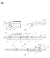
- FIG. 7 is a diagram showing various sections determined by the travel permission section setting process when the sub-links 66 are equally spaced by the vehicle management system 1, and (a) is set for each unmanned dump truck 20a, 20b. (B) is a travel permission section newly set for the unmanned dump truck 20a, and (c) is a release section. Since the traffic control server 31 exclusively sets the travel permission section, the description of the travel permission section processing also serves as the description of the processing for avoiding interference between the unmanned dump trucks 20a and 20b.
- the unmanned dump trucks 20a and 20b shown in FIG. 7 (a) are dump trucks that are running in the direction of arrow A.
- the travel permission section 73a is a travel permission section set for the unmanned dump truck 20a.
- the travel permission section 73b is a travel permission section set for the unmanned dump truck 20b.
- D1 is a travel permission remaining distance indicating a distance along the travel route 64 from the current position of the unmanned dump truck 20a to the front boundary point (terminal) of the travel permission section 73a.
- D2 is a travel permission request start distance for starting transmission of section request information.
- the travel permission request start distance D2 is a distance longer than the distance at which the unmanned dump truck 20a can be stopped, and is defined as a distance obtained by adding a predetermined offset distance to the stopable distance, for example. This is for stopping within the current travel permission section.
- the value of the offset distance is set in consideration of, for example, the time required for wireless communication and the degree of occurrence of wireless communication failure.
- the speed of the unmanned dump truck 20a may be obtained by measuring the current speed of the unmanned dump truck 20a from the rotational speed of the front wheels 22 or the rear wheels 23, and the travel position is included with respect to the current travel position of the unmanned dump truck 20a.
- the speed limit (maximum allowable speed) for each sublink 66 set in the map information stored in the master map information DB 316 and the terminal-side map information DB 266 in the sublink 66 may be used.
- the unmanned dump truck 20a transmits section request information to the traffic control server 31.
- the section request information includes the current position information of the unmanned dump truck 20a.
- the travel permission section setting unit 311b When the travel-permitted section setting unit 311b receives the section request information from the unmanned dump 20a, the travel permission section setting unit 311b includes a section where the unmanned dump 20a exists (a travel route between adjacent nodes 65) based on the positional information included in the transmitted section request information. 64) (corresponding to sublink 66 on 64). Then, a section extending from the end of the section where the unmanned dump truck 20a is traveling to a predetermined section ahead, that is, the number of sections, is set as a travel permission section toward the front in the traveling direction of the unmanned dump truck 20a. When there is a section where permission is given to another vehicle such as the unmanned dump truck 20b, the travel permission section is up to a section before that.
- the section where the unmanned dump truck 20a exists is 80, and the provisional travel permission section 85 is set as a provisional travel permission section.
- This provisional travel permission section 85 includes sections 81-84.
- the sections 83 and 84 are already given to the unmanned dump truck 20b as the travel permission section 73b. Therefore, candidates of the travel permission section 73a that can be newly set for the unmanned dump truck 20a are sections 81 and 82, but the section 81 is included in the travel permission section 73a that has already been set for the unmanned dump truck 20a. ing. Therefore, the travel permission section setting unit 311b sets only the section 82 as a new travel permission section 73a.
- the provisional travel permission section 85 set in the unmanned dump truck 20a by the travel permission section setting unit 311b is the travel permission section information on the travel route 64 stored in the travel permission section information DB 317 and the restriction for each sublink 66. Based on the speed information, it is set according to the speed limit information set for the section 80 where the unmanned dump truck 20a is currently traveling. Specifically, the travel position information detected by the position calculation device 29 of the unmanned dump truck 20a is transmitted to the server side communication device 314 via the terminal side communication device 264, and the unmanned operation is performed based on the travel position information. The travel position of the dump 20a is calculated, and a provisional travel permission section 85 set for the unmanned dump 20a is determined based on the speed limit set for the sublink 66 including the travel position.
- the travel permission section setting unit 311b increases the number of sublinks 66 as the provisional travel permission section 85 set for the unmanned dump 20a when the speed limit to which the travel position of the unmanned dump 20a that sets the travel permission section belongs is high.
- the speed limit is low, the number of sublinks 66 as the provisional travel permission section 85 is reduced.
- the speed limit for each sublink 66 on the travel route 64 corresponds to the topographic change of each sublink 66. For example, the change in the travel direction of the road surface of the sublink 66, for example, the smaller the gradient, the smaller the speed limit is shown in FIG.
- the smaller the radius of curvature of the curve section 67 is, the smaller it is, and the smaller the friction coefficient based on road surface conditions, such as gravel roads, crushed roads, unevenness, and muddyness, is set to be smaller.
- the travel permission section setting unit 311b gives the travel permission given to the unmanned dump truck 20b with respect to the sublink 66 through which the unmanned dump truck 20b passes among the sublinks 66 given travel permission to the preceding unmanned dump truck 20b. Release at a predetermined timing. Specifically, as shown in FIG. 7C, the travel permission section setting unit 311b determines that the distance D4 from the end of the sublink 83 to be released to the position of the unmanned dump truck 20b is a predetermined travel permission. When the distance is equal to or greater than the release distance D3, the travel permission given to the unmanned dump truck 20b in the sublink 83 is released. The released sublink 83 can be set as a travel permission section of the subsequent unmanned dump truck 20a.
- the travel permission section setting unit 311b In the processing by the travel permission section setting unit 311b, communication between the unmanned dump truck 20a and the traffic control server 31 occurs when the unmanned dump trucks 20a and 20b transmit a travel permission request and the traffic control server 31 travels. It is time to send a section. Therefore, the travel permission section setting unit 311b can cancel the travel permission section set for the unmanned dump trucks 20a and 20b, that is, can set the travel permission section for the unmanned dump trucks 20b and 20a other than the own vehicle. The release is also performed based on the position information transmitted simultaneously when the unmanned dump trucks 20a and 20b request the travel permission.
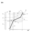
- FIG. 8 is a graph showing a change over time when the travel permission section is set according to the speed limit of each sublink 66 by the vehicle management system 1.
- the horizontal axis represents time
- the vertical axis represents the position on the travel route 64.
- the vertical axis is the position that travels along the road 64, and the road 64 is not necessarily a straight line.
- Sections 90 and 92 represent, for example, a straight line area or a section with a relatively high speed limit with good road surface conditions set on the map information stored in the master map information DB 316 or the terminal-side map information DB 266.
- a section 91 represents a sublink 66 having a relatively small speed limit due to a local sharp curve or a gradient.
- 94 is a time change of the position on the travel route 64 when the unmanned dump truck 20a travels at an ideal speed within the speed limit based on the speed limit set for each sublink 66.
- the travel permission section when the unmanned dump truck 20a travels is represented by blocks B1 to B3 in FIG.
- the length in the vertical direction of the blocks B1 to B3 represents the length of the travel-permitted section
- the length in the horizontal direction of the block B represents the time during which the travel-permitted section is maintained, that is, the travel time (travel time).
- the node 65 that originally represents the boundary of the sublink 66 is predetermined on the travel route 64, but in this description, the node 65 is set on the travel route 64 at a sufficiently narrow interval. Suppose that it is not shown in FIG.
- the travel permission request start distance D2 is L1
- the provisional travel permission section 85 is L2
- the travel permission release distance D3 is L3.
- the unmanned dump truck 20a is assumed to be at a position x0 in the travel permission section B1.
- the unmanned dump truck 20a travels in the travel permission section B1 in accordance with a speed limit determined in advance for each sublink 66, and the travel position of the unmanned dump truck 20a is equal to or less than the travel permission request start distance L1 from the end of the travel permission section B1.
- section request information and host vehicle position information are transmitted to the traffic control server 31 using wireless communication.
- the travel permission section setting unit 311b permits travel of a predetermined number of sublinks 66 belonging to the provisional travel permission section L2 to the unmanned dump truck 20a that has transmitted the information. At the same time, the travel permission of the sublink 66 that has become less than the travel permission cancellation distance L3 is canceled.
- the travel permission section for the unmanned dump truck 20a changes from B1 to B2 at time t1 by the travel permission and the release of the travel permission by the travel permission section setting unit 311b.
- the same processing is performed at time t2 and position x2, and the travel permitted section changes from B2 to B3.
- the travel permission section changes based on the parameters L1, L2, and L3.
- the provisional travel permission section L2 is large, that is, the sublink 66 is set as the provisional travel permission section L2. As the number is set larger, the frequency of communication associated with the update of the travel permitted section can be reduced. However, at the same time, since the same travel permission section is maintained while communication is not performed, if the provisional travel permission section L2 set as the travel permission section is too large, it is already set for the subsequent unmanned dump truck 20b. Travel permission cannot be permitted in the travel permitted section, and the travel interval between the unmanned dump trucks 20a and 20b is increased.
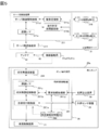
- FIG. 9 is a flowchart showing a process for calculating the provisional travel permission section L2 in response to the travel permission request for the unmanned dump truck 20a in the vehicle management system 1. That is, FIG. 9 is a processing flow when the travel permission section setting unit 311b calculates the provisional travel permission section L2 when the unmanned dump truck 20a makes a travel permission request to the traffic control server 31.
- step S1 the travel permission request start position Xr1 of the unmanned dump truck 20b is estimated (step S1, hereinafter, simply referred to as “S1” or the like).
- the unmanned dump based on the speed limit for each sublink 66 on the travel route 64 stored in the travel permission section information DB 317 in correspondence with the travel route 64 stored in the master map information DB 316 of the traffic control server 31, the unmanned dump The time ⁇ T2 until 20b reaches the current position Xc of the unmanned dump truck 20a from the position Xr1 is estimated (S2).
- the time tr when the unmanned dump truck 20b makes a travel permission request is estimated (S3).
- the temporary dump for the unmanned dump truck 20a to make a travel permission request by the time tr A travel permission section L2 is determined (S4).
- the provisional travel permission section L2 is determined and the travel permission is given to the unmanned dump truck 20a until the unmanned dump truck 20b traveling at a predetermined time interval T makes a next travel permission request until time tP.
- the unmanned dump truck 20a performs communication according to the next travel permission request. For this reason, the run permission section which has already run can be canceled to the maximum extent. That is, the unmanned dump truck 20b can reliably obtain permission for the next travel permitted section from the traffic control server 31 when the travel permission is requested at time tP. Therefore, it is possible to prevent the front section from waiting on the travel route 64 without being permitted to travel, and from opening the travel interval more than necessary.
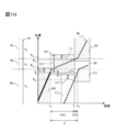
- FIG. 10 is a graph showing a change in position when two unmanned dump trucks 20a and 20b continuously travel on the same travel route 64 in the vehicle management system 1.
- the travel route 64 is the same as the route shown in FIG. 8, and the sections 90 to 92 have different speed limits, and the speed limits are assumed to be V1 to V3.
- the end position of the section 90 and the start position of the section 91 is Xa
- the end position of the section 91 and the start position of the section 92 is Xb.
- the current position of the preceding unmanned dump truck 20a i.e., the travel position
- the current position of the subsequent unmanned dump truck 20b i.e., the travel position
- the travel permission sections of the respective unmanned dump trucks 20a, 20b are B, C. Show.
- the travel interval between the unmanned dump trucks 20a and 20b that is, the time interval during which the unmanned dump trucks 20a and 20b pass through the same position is T.
- the current time is tc1
- the current position of the unmanned dump truck 20a is Xc.
- the solid line portion is a track traveled before the current time tc1
- the broken line portion is a track scheduled to travel after the current time tc1.
- the unmanned dump truck 20a transmits section request information to the traffic control server 31 when the current position Xc reaches a position that is less than or equal to the travel permission request start distance L1 from the end of the travel permission section B1, that is, at time tc1. . Thereafter, the travel permission section setting unit 311b of the traffic control server 31 calculates a provisional travel permission section L2 for the unmanned dump truck 20a.
- the provisional travel permission section L2 cancels the travel permission in the rear section from the position obtained by subtracting the travel permission release distance L3 from the current position Xc of the unmanned dump truck 20a when updating the travel permission section of the unmanned dump truck 20. For this reason, traveling permission to the position where traveling permission is canceled can be given to the subsequent unmanned dump truck 20b.
- the position Xr1 where the unmanned dump truck 20b makes a travel permission request later is given by the following formula (1). Is calculated by
- the time tc2 at which the unmanned dump truck 20b reaches the current position tc1 of the unmanned dump truck 20a is calculated by the following equation (2) using the time interval T indicating the travel interval of the unmanned dump trucks 20a and 20b.
- the time tr when the unmanned dump truck 20b reaches the travel permission request position Xr1 is calculated by the following formula (4).
- the time ⁇ T1 from the current time tc1 to tr is calculated by the following equation (5).
- Xr2 is calculated by the following equation (7) based on the provisional travel permission section L2 to be obtained.
- provisional travel permission section L2 is calculated using these formulas (6) and (7).
- Expression (6) it is desirable that the difference between both sides is as small as possible.
- the calculation is performed assuming a specific travel route 64, but the actual travel route 64 has various speed patterns with different speed limits for each sub-link 66.
- the provisional travel permission section L2 is determined from the following formula (8) with respect to the current position Xc of the unmanned dump truck 20a.
- V (x) in Expression (8) is a speed limit set for each sublink 66 on the travel route 64.
- the travel permission section setting unit 311b sets a part of the section on the travel route 64 as the travel permission section for the plurality of unmanned dump trucks 20a to 20c. In doing so, based on the travel permitted section information on the travel route 64 stored in the travel permitted section information DB 317 and the speed limit information for each sublink 66, the unmanned dump trucks 20a to 20c traveling in the predetermined sublink 66 are provided. On the other hand, according to the speed limit information of the sublink 66, when the speed limit is large, the provisional travel permission section 85 is set large, and when the speed limit is low, the provisional travel permission section 85 is set small.
- a section excluding the travel permission section already set for the other unmanned dump trucks 20a to 20c is set as a travel permission section.
- the travel permitted section information based on the permitted section is transmitted from the server side communication device 314 to the terminal side communication device 264 of the unmanned dump truck 20a.
- each unmanned dump 20a-20c travels in each travel permission section set without duplication for a plurality of unmanned dumps 20a-20c, mutual interference of these unmanned dumps 20a-20c can be prevented.
- the suitable travel permission section is set to such an extent that the travel interval of the unmanned dump trucks 20a to 20c does not become too large. Can be set. Therefore, since the travel intervals of these unmanned dump trucks 20a and 20b do not become too large, the communication amount between the terminal side communication device 264 and the server side communication device 314 accompanying the transmission of the section request information and the travel permission section information associated with the travel permission section.
- the unmanned dump trucks 20a to 20c can be driven without lowering the operation density. Therefore, a plurality of unmanned dump trucks 20a to 20c can be run without interference while maintaining a necessary operation density with a small communication amount.
- the speed limit of each sub-link 66 is the change in the traveling direction of the sub-link 66 (for example, curve curvature), slope (for example, slope), road surface condition (road surface conditions such as gravel roads, crushed roads, etc.). It depends on. Therefore, the speed limit set for each of the sublinks 66 is set by changing according to the change in the travel direction, the inclination, and the road surface condition in each of the sublinks 66, and the travel permission set by the travel permission section setting unit 311b. By changing the section according to the speed limit, it is possible to more appropriately secure the travel intervals of the plurality of unmanned dump trucks 20a to 20c in which the travel permission section is set.
- the second embodiment is an embodiment in which a traveling time that is a passing time in the travel permitted section is made constant.
- the second embodiment will be described below with reference to FIG.
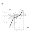
- FIG. 11 is a graph showing a change over time of the travel permission section set in the unmanned dump trucks 20a and 20b in the vehicle management system 1 according to the second embodiment of the present invention. That is, FIG. 11 shows the positions of the unmanned dump trucks 20a and 20b and the travel permitted sections when the provisional travel permitted section L2 is determined so that the time during which the unmanned dump trucks 20a and 20b travel within the travel permitted section is constant. Shows the relationship. In FIG. 11, the description of the same reference numerals as those in FIG. 10 is omitted.
- ⁇ T is a time required for the unmanned dump trucks 20a and 20b to travel within one travel permission section.
- a provisional travel permission section L2 for setting the next travel permission section B2 is obtained.
- the position x2 when traveling for the required time ⁇ T in the current speed section is calculated by the following equation (9).
- provisional travel permission section L2 is computed by the following formula (12).
- xT is calculated by the following equation (13). Also in this case, the provisional travel permission section L2 is calculated by Expression (12).
- the calculation method of the provisional travel permission section L2 according to the second embodiment can also update the travel permission section with the required time ⁇ T, thus preventing the problem that the travel interval between the unmanned dump trucks 20a and 20b is unnecessarily widened. it can. That is, the unmanned dump trucks 20a and 20b are traveled in a predetermined section on the travel path 64 through a predetermined time interval while securing a travel interval between the unmanned dump trucks 20a and 20b traveling on the travel path 64. be able to. Therefore, each unmanned dump truck 20a, 20b can be made to run, without reducing operation density, preventing mutual interference of these unmanned dump trucks 20a, 20b.
- the speed limit set for each sublink 66 on the travel route 64 is stored in the travel permission section information DB 317 and travel permission from the unmanned dump truck 20a traveling on the predetermined sublink 66 is permitted.
- the number of sublinks 66 ahead of the current travel position as the travel permission section is set according to the speed limit set for the predetermined sublink 66.
- the traffic control server 31 receives the actual speed information of the unmanned dump 20a at the time of requesting the travel permission together with the section request information from the unmanned dump 20a, or the traffic control server 31 calculates the actual speed information of the unmanned dump 20a. It is good also as a structure which sets a driving
- the unmanned dump truck 20a loads a large amount of earth and sand, minerals, etc. on the loading platform 24, the actual traveling speed that can be output varies depending on whether it is empty or loaded. The speed changes. For example, when the load is loaded, the traveling speed is reduced due to the weight of the load, and when the load is empty, the traveling speed is not decreased due to the weight of the load. For this reason, in addition to the speed limit set for each sub-link 66, the travel permission section may be corrected according to the load status loaded on the loading platform 24 of the unmanned dump truck 20a.
- the unmanned dump truck 20a in the unloaded state has a small total weight and can increase the traveling speed, the travel permission section is set longer, and the unmanned dump truck 20a in the loaded state has a total weight including the load. Since it is large, the travel permission section is made shorter.
- the loading state of the unmanned dump truck 20a is detected by a pressure sensor (not shown) attached to a hoist cylinder or the like that supports the loading platform 24, the position on the travel path 64, the travel direction of the unmanned dump truck 20a, and the like.
- It may be configured to calculate from As a result, it is possible to prevent variations in the travel intervals of the unmanned dump trucks 20a and 20b due to the difference in the load state, and to more appropriately secure the travel intervals of the unmanned dump trucks 20a to 20c.
- the travel permission section set for each unmanned dump truck 20a to 20c is set so that the travel time in all travel permission sections is constant, but at least a part of the travel route 64 is on the travel route 64.
- the travel permission section may be set such that the travel time of the sublink 66 is constant, or a predetermined sublink 66 or a predetermined point on the travel route 64 is passed after a predetermined time.
- the time intervals of the unmanned dump trucks 20a to 20c passing through the predetermined section that is, the travel intervals can be made constant, and the unmanned dump trucks 20a to 20c can be traveled through the predetermined section through the predetermined time intervals.
Landscapes
- Engineering & Computer Science (AREA)
- Physics & Mathematics (AREA)
- General Physics & Mathematics (AREA)
- Radar, Positioning & Navigation (AREA)
- Remote Sensing (AREA)
- Aviation & Aerospace Engineering (AREA)
- Automation & Control Theory (AREA)
- Traffic Control Systems (AREA)
- Control Of Position, Course, Altitude, Or Attitude Of Moving Bodies (AREA)
Abstract
少ない通信量で必要な運行密度を保ちつつ、複数の車両が干渉なく走行できる車両管理システムを提供する。複数の無人ダンプ20a~20cのそれぞれに対して重複なく、走行経路64上の一部の区間を走行許可区間として設定する走行許可区間設定部311bを有する。走行許可区間設定部311bは、走行許可区間情報DB317に記憶した区間情報および制限速度情報に基づき、所定のサブリンク66間を走行する無人ダンプ20aに対し走行許可区間として設定する。走行許可区間設定部311bは、所定のサブリンク66より前方のサブリンク66数を、所定のサブリンク66に定められた制限速度に応じて設定する。
Description
本発明は、予め定めた走行経路に沿って走行する複数の車両の走行を管理する車両管理システムに関する。
露天掘り鉱山などでは、掘削した鉱石を搬送するダンプトラックなどの複数の自律走行車両を無人運転する場合、車両同士が干渉しないように制御する必要がある。この必要性から、従来は、これら複数の自律走行車両の走行を管理する管制局を設け、無線で自律走行車両と管制局との間の情報をやり取りして制御する車両管制方式がとられている。
具体的に、この種の車両管制方式に関する従来技術として、特許文献1には、車両の現在位置を所定時間間隔、あるいは所定距離移動毎等のタイミングで管制局に送信し、管制局は、これら車両位置の相互関係から相互の干渉が起きないように、走行の継続、減速、停止等の指示を各車両に送信する。また、近い距離にある車両同士については、車両間で無線通信を行って相互の位置情報を交換し合い、相互に干渉しないように走行させる。
また、特許文献2においては、管制局から各車両に対し、車両位置に応じて他の車両と干渉せずに走行できる領域を走行許可領域として無線通信にて指示する。各車両は、与えられた走行許可領域に従って走行することで、相互の干渉を防止している。
上記特許文献1では、所定時間毎あるいは所定距離移動毎に車両と管制局間で通信を行うため、各車両において通信が頻繁に発生する。一方で、鉱山等の広大な領域において長距離通信を行う場合は、無線通信の特性から一般的に通信帯域が狭くなり、使用可能な通信量に制限が生じてしまう。このため、上記特許文献1のように通信の頻度が多い車両管制方式では、多数の車両の走行を同時に管理することができないという課題がある。
また、上記特許文献2では、車両に対し走行許可領域を設定することにより、走行許可領域内での通信を行わなくても車両間の干渉を防止できる。本特許文献2においては、一度に与える走行許可領域を大きく設定することで、その更新頻度を少なくし、通信量を低減することが可能である。しかしながら、走行許可領域を過剰に長く設定すると車両間の走行間隔が大きくなってしまい、車両の運行密度が下がってしまうという課題がある。この課題は、鉱山においては生産量の低下につながり、非常に大きな問題である。
本発明は、上記課題を解決するためになされたものであり、少ない通信量で必要な運行密度を保ちつつ、複数の車両が干渉なく走行できる車両管理システムを提供することを目的とする。
この目的を達成するために、本発明は、予め定めた走行経路を複数の区間として分割し、前記走行経路に沿って走行する複数の車両の走行を、前記区間を基準として管理する車両管理システムであって、前記複数の車両のそれぞれに対して重複なく、前記走行経路上の一部の区間を走行許可区間として設定する走行許可区間設定部と、前記走行経路の各区間に関する区間情報、および前記区間情報中の区間毎に予め定めた走行速度情報を記憶した記憶部と、前記走行許可区間設定部にて設定した前記走行許可区間の情報を、前記走行許可区間を設定した前記車両へ送信する通信部と、前記車両に取り付けられ、前記通信部が送信する前記走行許可区間の情報を受信するための車載通信部と、を備え、前記走行許可区間設定部は、前記記憶部に記憶した区間情報および前記走行速度情報に基づき、所定の区間を走行する車両に対し走行許可区間として設定し、前記走行許可区間設定部は、前記所定の区間より前方の区間数を、前記所定の区間に定められた走行速度に応じて設定する、ことを特徴とする。
このように構成した本発明は、走行経路上の各区間の区間情報と、これら区間毎に予め定めた走行速度情報とに基づき、所定の区間を走行する車両に対し走行許可区間として設定する区間数を、所定の区間に定められた走行速度に応じて設定する。すなわち、所定の区間の走行速度に応じた走行許可区間としての区間数の設定により、複数の車両の走行間隔が大きくなり過ぎない程度で、好適な走行許可区間を設定することが可能となる。よって、複数の車両の走行間隔が大きくなり過ぎないため、走行許可区間の情報の送信に関する通信量を少なくできるとともに、これら複数の車両の運行密度を保ちつつ、これら複数の車両を干渉なく走行させることができる。
また、本発明は上記構成において、前記走行許可区間設定部は、前記走行許可区間を設定する車両と、この車両に後続する他の車両との走行間隔が、所定の距離となるように、前記各車両に対する前記走行許可区間を設定する、ことを特徴とする。そのため、本発明は、走行許可区間を設定する車両と、この車両に後続する他の車両との走行間隔を、所定の距離として維持させつつ、これら車両それぞれの走行を管理することができる。よって、これら車両の相互の干渉を防止できるとともに、これら車両の走行間隔が大きくなり過ぎないようにすることにより、これら車両の運行密度を下げることなく、各車両を走行させることができる。
また、本発明は上記構成において、前記走行許可区間設定部は、前記複数の区間のうちの少なくとも一部の区間の通過時間が一定になるように前記走行許可区間を設定する、ことを特徴とする。そのため、本発明は、走行経路上の複数の区間のうちの一部の区間の通過時間を一定にでき、この一部の区間の走行速度を定めていることから、この一部の区間における複数の車両の車両間隔を維持することができる。よって、複数の車両の相互の干渉を防止できるとともに、これら車両の走行間隔が大きくなり過ぎないようにすることにより、これら車両の運行密度を下げることなく、各車両を走行させることができる。
また、本発明は上記構成において、前記走行許可区間設定部は、前記走行経路上の所定の地点を、前記走行許可区間を設定する車両が通過してから、この車両に後続する他の車両が通過するまでの時間間隔が一定となるように前記走行許可区間を設定する、ことを特徴とする。そのため、本発明は、所定の車両が走行経路上の所定の地点を通過してから、この車両に後続する他の車両が当該所定の地点を通過するまでの時間間隔を一定にできる。よって、走行経路上の区間毎の走行速度を定めているため、走行経路上の所定の地点を通過する複数の車両の走行間隔を維持することができる。したがって、複数の車両の相互の干渉を防止できるとともに、これら車両の走行間隔が大きくなり過ぎないようにすることにより、これら車両の運行密度を下げることなく、各車両を走行させることができる。
また、本発明は上記構成において、前記走行速度情報は、前記走行経路上の各区間における走行方向の変化、傾きおよび路面状態に応じて前記区間毎に設定されている、ことを特徴とする。各区間の走行速度は、その区間の走行方向の変化(例えば、カーブ曲率)、傾き(例えば、勾配)、路面状態(砂利道、踏み固められた道等の路面状況)によって変化する。そこで、本発明は、これら区間毎の走行速度を、これら各区間における走行方向の変化、傾きおよび路面状態に応じて区間毎に設定することにより、走行経路上の各区間の地形的な変化に対応させて複数の車両の走行許可区間を設定することができ、これら複数の車両の走行間隔をより適切に確保することが可能となる。よって、これら複数の車両の相互の干渉をより適切に防止でき、運行密度を下げずに各車両を走行させることができる。
また、本発明は上記構成において、前記車両は、ダンプトラックであり、前記ダンプトラックの積荷状態を検出する積荷状態検出部を備え、前記走行許可区間設定部は、前記区間情報および前記走行速度情報に加え、前記積荷状態検出部にて検出した前記ダンプトラックの積荷状態情報に応じて、前記走行許可区間を設定する、ことを特徴とする。一般に、ダンプトラックは、その積載状態に応じて実際の走行速度が変化(例えば、積荷を積載している状態では積荷の重量により速度が低下してしまい、空荷の状態では積荷の重量に伴う速度低下がない。)する。このため、本発明は、走行経路上の区間情報、および各区間における走行速度情報に加え、積荷状態検出部にて検出したダンプトラックの積荷状態情報に応じて、走行許可区間を設定することにより、積荷状態の相違によるダンプトラック間の走行間隔のばらつきを防止でき、これら複数のダンプトラックの走行間隔をより適切に確保することができる。
本発明によれば、所定の区間の走行速度に応じた走行許可区間としての区間数の設定により、複数の車両の走行間隔が大きくなり過ぎない程度で、好適な走行許可区間を設定することができる。よって、複数の車両の走行間隔が大きくなり過ぎないため、走行許可区間の情報の送信に関する通信量を少なくでき、これら複数の車両の運行密度を保ちつつ、これら複数の車両を干渉なく走行させることができる。上記した以外の課題、構成及び効果は、以下の実施形態の説明により明らかにされる。
以下、本発明の実施形態を図面に基づいて詳細に説明する。なお、各実施形態を説明するための全図において、同一の機能を有する部材には同一または関連する符号を付し、その繰り返しの説明は省略する。また、以下の各実施形態では、特に必要なとき以外は同一または同様な部分の説明を原則として繰り返さない。
<第1実施形態>
本第1実施形態は、鉱山においてショベルやホイールローダ等の積込機が積み込んだ土砂や鉱石を搬送し、運転手が搭乗することなく自律走行する無人ダンプ(無人車両に相当する)と、これら無人ダンプの干渉を回避するために交通管制を行う交通管制サーバと、を無線通信回線で接続した車両管理システムに係り、特に少ない通信量で必要な運行密度を保ちつつ、複数のダンプトラックを干渉なく走行させるための構成に特徴がある。以下、本発明の第1実施形態に係る車両管理システムについて、図面を参照しながら説明する。
本第1実施形態は、鉱山においてショベルやホイールローダ等の積込機が積み込んだ土砂や鉱石を搬送し、運転手が搭乗することなく自律走行する無人ダンプ(無人車両に相当する)と、これら無人ダンプの干渉を回避するために交通管制を行う交通管制サーバと、を無線通信回線で接続した車両管理システムに係り、特に少ない通信量で必要な運行密度を保ちつつ、複数のダンプトラックを干渉なく走行させるための構成に特徴がある。以下、本発明の第1実施形態に係る車両管理システムについて、図面を参照しながら説明する。
まず、図1に基づいて、第1実施形態に係る車両管理システムの概略構成について説明する。図1は、本発明の第1実施形態に係る車両管理システムの構成を示す概略図である。図1に示す車両管理システム1は、鉱山などの採石場で、土砂や鉱石の積込作業を行うショベル10a,10bから積み込まれた土砂や鉱石等の積荷を搬送するための鉱山用のダンプトラックである無人ダンプ20a,20bと、採石場の近傍または遠隔の管制局である管制センタ30に設置された交通管制サーバ31とを、無線通信回線40を介して互いに通信接続して構成された交通管理システムである。
各無人ダンプ20a,20bは、鉱山内で予め設定された搬送路60に沿ってショベル10a,10b及び図示しない放土場の間を往復し、積荷を搬送する。鉱山内には、複数の無線基地局41a~41cが設置される。そして、これらの無線基地局41a~41cを経由して、無線通信の電波が送受信される。
ショベル10a,10bおよび無人ダンプ20a、20bは、全地球航法衛星システム(GNSS:Global Navigation System)の少なくとも3つの航法衛星50a~50cから測位電波を受信して自車両の位置を取得するための位置算出装置29(図4参照。)を備える。GNSSとして、例えばGPS(Global Positioning System)、GLONASS(Global Navigation Satellite System)、GALILEOを用いてもよい。無人ダンプ20a,20bは、実際には2台以上存在し、それぞれの無人ダンプ20a,20b,・・・が交通管制サーバ31と無線で通信を行い、その構成は同じであるため、以下ではショベル10aおよび無人ダンプ20aを例に挙げて説明する。
ショベル10aは、超大型の油圧ショベルであって、走行体11と、この走行体11上に旋回可能に設けた旋回体12と、運転室13と、旋回体12の前部中央に設けたフロント作業機14とを備えている。フロント作業機14は、旋回体12に対し俯仰動可能に設けられたブーム15と、ブーム15の先端に回動可能に設けられたアーム16と、アーム16の先端に取り付けられたバケット17とを含む。ショベル10aにおける見通しの良い場所、例えば運転室13の上部には、無線通信回線40に接続するためのアンテナ18が設置されている。
図3は、車両管理システム1にて運行管理する無人ダンプ20aの構成を示す斜視図である。無人ダンプ20aは、図1および図3に示すように、本体を形成するフレーム21と、前輪22および後輪23と、フレーム21の後方部分に設けられたヒンジピン(図示せず)を回動中心として上下方向に回動可能な荷台24と、荷台24を上下方向に回動させる左右一対のホイストシリンダ(図示せず)と、を含む。また、無人ダンプ20aは、見通しの良い場所、例えば無人ダンプ20aの前輪22および後輪23よりも上側に取り付けられたデッキ280の前方に、無線通信回線40に接続するためのアンテナ25が設置されている。また、無人ダンプ20aのホイストシリンダには、荷台24に積載した積荷の荷重を検出するための圧力センサ(図示せず)が設けられている。
無人ダンプ20aは、交通管制サーバ31からの指示に従って自律走行するための車載端末装置としてのダンプ端末装置26を搭載する。交通管制サーバ31は、無線通信回線40に接続するためのアンテナ32に接続され、このアンテナ32および無線基地局41a~40cを経由してダンプ端末装置26のそれぞれと通信する。
図2は、図1中の搬送路60を詳述した図であり、無人ダンプ20aが走行する露天掘り鉱山現場の構成例を示す。鉱山現場には、ショベル10aによる掘削現場61が設けられている。ショベル10aは、掘削現場61で掘った表土や鉱石を無人ダンプ20aに積み込む。よって、掘削現場61は、積込位置を含む。
また、鉱山現場には、表土を展開する放土場62が設けられている。無人ダンプ20aが掘削現場61から搬送した表土等は、放土場62で放土され、層状あるいは放射状に展開される。さらに、鉱山現場には、鉱石を破砕処理するクラッシャ(図示せず)等が設置された放土場63が設けられている。クラッシャが破砕した鉱石は、ベルトコンベアなどにより貨車による積み出し場あるいは処理設備等へ搬送される。無人ダンプ20aは、掘削現場61で表土や鉱石を積込む。無人ダンプ20aは、搬送路60を走行して、積み込んだ表土や鉱石を放土場62,63へ搬送する。
掘削現場61において、ショベル10aが表土を掘削している場合に、無人ダンプ20aは、掘削現場61と放土場62との間を往復する。掘削現場61において、ショベルが鉱石を掘削している場合に、無人ダンプ20aは、掘削現場61と放土場63との間を往復する。このため、搬送路60は、掘削現場61および放土場62を結ぶ搬送路と、掘削現場61および放土場63を結ぶ搬送路60とを含んでいる。また、搬送路60上には、鉱山の地形等に応じたカーブ区間67が設けられている。
また、搬送路60上には、各無人ダンプ20a~20cの進行方向が異なる二つの走行経路64が設けられている。各走行経路64は、上り車線および下り車線を構成する。無人ダンプ20aは、搬送路60上を一般の道路等と同じように、例えば右側通行で走行する。走行経路64は、地図上で設定された座標値として与えられる。具体的には、交通管制サーバ31と各無人ダンプ20a~20cとのそれぞれに、同一の地図情報を格納する。この地図情報は、地図上にある地点、すなわちノード65と、このノード65の座標値とを含む。走行経路64は、複数のノード65、および隣接するノード65を接続する区間としてのサブリンク66にて複数に分割されて定義される。
次に、上記第1実施形態に係る交通管制サーバ31、無人ダンプ20aおよびダンプ端末装置26それぞれのハードウェア構成について、図4を参照して説明する。図4は、車両管理システム1のハードウェア構成図である。
図4に示すように、交通管制サーバ31は、サーバ側制御装置311、サーバ側入力装置312、サーバ側表示装置313、サーバ側通信装置314、通信バス315、マスタ地図情報データベース(以下データベースを「DB」と略記する)316、および走行許可区間情報DB317を含む。
サーバ側制御装置311は、交通管制サーバ31の各構成要素の動作を制御するものであり、CPU(Central Processing Unit)等の演算・制御装置のほか、交通管制サーバ31で実行されるプログラムを格納するROM(Read Only Memory)やHDD(Hard Disk Drive)等の記憶装置、およびCPUがプログラムを実行する際の作業領域となるRAM(Random Access Memory)を含むハードウェアを用いて構成される。また、サーバ側制御装置311は、交通管制サーバ31で実行される機能を実現するための集積回路(ASIC:application specific integrated circuit)を用いて構成してもよい。
サーバ側入力装置312は、マウスまたはキーボード等の入力装置にて構成され、無人ダンプ20aの状態表示や、無人ダンプ20aへのマニュアル指示を入力するためのユーザインタフェースとして機能する。
サーバ側表示装置313は、液晶モニタ等にて構成され、交通管制サーバ31を操作等するオペレータに対して情報を表示して提供するインターフェースとして機能する。
サーバ側通信装置314は、有線/無線ネットワークとの通信接続を行う装置にて構成される通信部である。サーバ側通信装置314は、有線通信回線33を介してアンテナ32に接続され、無線通信回線40を介して無線基地局41a~41cに接続される。
通信バス315は、交通管制サーバ31の各構成要素、すなわちサーバ側制御装置311、サーバ側入力装置312、サーバ側表示装置313、サーバ側通信装置314、通信バス315、マスタ地図情報DB316および走行許可区間情報DB317のそれぞれを互いに電気的に接続する。
マスタ地図情報DB316は、HDD等の情報を固定的に記憶する記憶装置を用いて構成され、搬送路60上の各ノード65の位置情報(座標値)と、各ノード65を連結するサブリンク66とで定義された地図情報(走行経路情報)を記憶する。ここで、マスタ地図情報DB316には、鉱山の地形情報や、各ノード65の絶対座標(測位電波を基に算出される3次元実座標)を含んでもよい。各ノード65には、そのノード65を固有に識別する位置識別情報、すなわちノードIDが付与される。
走行許可区間情報DB317は、HDD等の情報を固定的に記憶する記憶装置を用いて構成され、各無人ダンプ20aを固有に識別する車両識別情報と、各無人ダンプ20aに割り当てられた走行許可区間を示す位置情報と、各無人ダンプ20aの現在位置における実際の走行速度に関する実速度情報と、走行経路64を複数に分割した区間に関する区間情報と、これら区間毎に応じて予め定めた制限速度(走行速度)に関する制限速度情報とを含む走行許可区間情報を記憶する。
マスタ地図情報DB316および走行許可区間情報DB317は、地図情報および走行許可区間情報を記憶する記憶部だけを備え、これらマスタ地図情報DB316および走行許可区間情報DB317の更新・検索処理をサーバ側制御装置311で行ってもよいし、これらマスタ地図情報DB316および走行許可区間情報DB317のそれぞれに、情報の更新・検索処理を行うエンジンを搭載したものでもよい。
一方、無人ダンプ20aは、電気駆動式のダンプトラックであって、ダンプ端末装置26のほか、ダンプ端末装置26の指示を受けて無人ダンプ20aの加減速やステアリングを制御する車両制御装置27、外界センサ装置28、および位置検出装置29を備える。
ダンプ端末装置26は、無線基地局41a~41cを経由して交通管制サーバ31に無線通信接続される。また、ダンプ端末装置26は、端末側制御装置261、端末側入力装置262、端末側表示装置263、端末側通信装置264、通信バス265、および端末側地図情報DB266を含んで構成される。
端末側制御装置261、端末側入力装置262、端末側表示装置263、端末側通信装置264、通信バス265および端末側地図情報DB266のそれぞれは、サーバ側制御装置311、サーバ側入力装置312、サーバ側表示装置313、サーバ側通信装置314、通信バス315およびマスタ地図情報DB316のそれぞれと同一の構成であるため、重複説明を省略する。端末側地図情報DB266は、マスタ地図情報DB316に格納された地図情報と同じ地図情報を格納している。
車両制御装置27は、リターダブレーキ271、サービスブレーキ272、ステアリング制御装置273および加速制御装置274を含む。車両制御装置27は、ダンプ端末装置26に電気的に接続され、交通管制サーバ31からの指示に従って無人ダンプ20-1を自律走行させる。
リターダブレーキ271は、通常制動時に使用するブレーキである。リターダブレーキ271は、電気駆動エンジンを構成する電動機を発電機として作動させ、運動エネルギーを電気エネルギーに変換して回生電力を生成し、これを抵抗器に印加して熱エネルギーとして消費させることで制動力を得る。
サービスブレーキ272は、緊急制動時に使用するブレーキであり、機械ブレーキにて構成される。サービスブレーキ272の頻回の使用は、機械ブレーキの構成部品、例えばブレーキパッドやディスクの摩耗を招く。従って、本実施形態では、緊急度に合わせてリターダブレーキ271とサービスブレーキ272とを使い分ける。
ステアリング制御装置273は、無人ダンプ20aのステアリング角度を調整する。加速制御装置274は、無人ダンプ20aの加速、減速の調整を行う。
外界センサ装置28は、図3に示すように、無人ダンプ20aのデッキ280の両側部にそれぞれ取り付けられたレーザレーダセンサ281,282と、無人ダンプ20aのデッキ280より下方の前側中心部に取り付けられたミリ波レーダセンサ283とを備える。レーザレーダセンサ281,282は、無人ダンプ20aが走行する走行経路64の路肩位置を検出する。ミリ波レーダセンサ283は、無人ダンプ20aの走行方向前方の障害物を検出する。これらレーザレーダセンサ281,282およびミリ波レーダセンサ283による外界センサ装置28の検知結果は、ダンプ端末装置26の端末側制御装置261に出力され、通常時は走行経路64から離脱しないように走行位置の監視や加減速に用いられ、緊急時には緊急回避行動に必要な制動動作に用いられる。
なお、走行経路64の路肩を検出する手段としては、必ずしもレーザレーダセンサ281,282である必要はなく、カメラを用いた画像処理にて路肩を検出してもよい。この場合において、カメラは、無人ダンプ20aの側方を見おろすように設置する。また、走行方向前方の障害物を検出する手段としては、必ずしもミリ波レーダセンサ283である必要はなく、ステレオカメラにて検出してもよい。この場合に、ステレオカメラは、無人ダンプ20aの前方に向けて設置された複数台のカメラとなる。また、ミリ波レーダセンサ283は、図3に示すデッキ280よりもさらに上方とし、路面を見下ろすように設置してもよい。
位置算出装置29は、航法衛星50a~50cからの測位電波に基づいて自車両の現在位置(自己位置)を算出する。算出された自車両の現在位置は、ダンプ端末装置26から交通管制サーバ31へ送信される。
次に、上記第1実施形態に係る交通管制サーバ31およびダンプ端末装置26の機能構成について、図5を参照して説明する。図5は、交通管制サーバ31およびダンプ端末装置26の主な機能を示すブロック図である。
図5に示すように、交通管制サーバ31のサーバ側制御装置311は、配車管理部311a、走行許可区間設定部311b、サーバ側通信制御部311d、および通信インターフェース(以下「通信I/F」と略記する)311eを備える。
配車管理部311aは、無人ダンプ20aの目的地を設定し、マスタ地図情報DB316に格納された地図情報を参照して現在位置から目的地に至る走行経路64を決定する。配車管理部311aの処理例としては、例えば無人ダンプ20aが駐機場にいる場合、積込位置を含む積込場の入口を目的として設定する。そして、配車管理部311aは、駐機場から積込上の入口に至るまでの走行経路64を設定する。なお、配車管理部311aは、走行経路64の設定に際し、積込位置の移動に伴って動的に走行経路64を設定してもよい。さらに、配車管理部311aは、無人ダンプ20aが積込位置に入る場合には積載物の内容によって放土場62,63のいずれかを目的地として設定し、この目的地に至るまでの走行経路64を設定する。
走行許可区間設定部311bは、例えば無人ダンプ20aに対し、マスタ地図情報DB316に格納された地図情報を参照し、決定された走行経路64上のノード65間として規定されるサブリンク66毎に走行許可の付与または解除を行い、少なくとも1つ以上のサブリンク66を含む区間(一部の区間)を、無人ダンプ20aの走行を許可する走行許可区間として設定し、この設定した走行許可区間の走行経路64中の位置を示す走行許可区間情報を生成する。特に、走行許可区間設定部311bは、運行管理する複数の無人ダンプ20a~20cに対して重複なく、これら複数の無人ダンプ20a~20cに対し、走行経路64上の部分区間を走行許可区間として設定する。
走行許可区間設定部311bは、走行許可区間情報DB317に格納された走行許可区間情報に対し、新たに生成した走行許可区間情報を上書きして更新する。走行許可区間情報には、走行許可区間の最前端のノード65である前方境界点のノードID、及び最後端のノード65である後方境界点のノードIDを含む位置情報が含まれる。走行許可区間設定部311bは、ダンプ端末装置26から新たな走行許可区間の設定を要求する区間要求情報を受信した場合に、この区間要求情報の受信に応じて走行許可区間の設定処理を行う。走行許可区間設定部311bは、新たな走行許可区間を設定した際にはその走行許可区間の走行許可区間情報を生成し、この走行許可区間情報の生成ができない場合には走行不許可を示す応答情報を生成する。
サーバ側通信制御部311dは、ダンプ端末装置26との間の無線通信制御を行う。具体的に、サーバ側通信制御部311dは、無人ダンプ20aの制動を指示する制動指示情報と、走行許可区間情報または応答情報とのそれぞれをダンプ端末装置26に送信する。サーバ側通信制御部311dは、ダンプ端末装置26から、無人ダンプ20aからの走行区間要求に関する区間要求情報、無人ダンプ20aの位置算出装置29が算出した自車両の位置を示す無人ダンプ位置情報、および無人ダンプ20aの実速度情報を受信する。実速度情報は、位置情報の変化量を基に走行方向および速さ(スカラ量)を含む速度(ベクトル)を示す情報として構成してもよいし、無人ダンプ20aに搭載したジャイロセンサ等の車体の向きを検出するセンサの出力結果と車輪の回転数から求めた速さとを組み合わせた情報として構成してもよい。
通信I/F311eは、USB(Universal Serial Bus)規格の接続端子等、サーバ側通信装置314と通信接続をするためのハードウェアにて構成される。
ダンプ端末装置26の端末側制御装置261は、自律走行制御部261a、端末側通信制御部261b、通信I/F261c、および要求情報処理部261dを備える。
自律走行制御部261aは、位置算出装置29から自車両の現在位置を取得し、端末側地図情報DB266の地図情報を参照して、走行許可区間情報に含まれる走行許可区間に従って自車両を走行させるための制御を車両制御装置27に対して行う。自律走行制御部261aは、外界センサ装置28の検知結果に基づいて前方障害物の有無を判定し、障害物との干渉、衝突の回避動作の有無も判定し、必要に応じ無人ダンプ20aを制動制御する。
自律走行制御部261aは、交通管制サーバ31からの指示に従って、車両制御装置27に対する駆動制御を行い、減速動作、通常停止動作、または緊急停止動作を行い、無人ダンプ20a~20c同士の干渉を避けるように走行制御する。また、自律走行制御部261aは、端末側地図情報DB266に記憶されている制限速度情報を参照しながら、走行経路64上の各サブリンク66を、これらサブリンク66毎に定めたられた制限速度以内の適切な速度で走行する。
端末側通信制御部261bは、交通管制サーバ31との間で行う無線通信の制御を行う。端末側通信制御部261bは、区間要求情報の送信と、走行許可区間情報または応答情報、制動指示情報の受信とを行う。通信I/F261cは、USB規格の接続端子等であり、端末側通信装置264と通信接続をするためのハードウェアにて構成される。
要求情報処理部261dは、端末側地図情報DB266に格納された地図情報、および位置算出装置29が算出した現在位置を基に、無人ダンプ20aが区間要求情報を送信する地点に到達したかを判断し、要求地点に到達すると区間要求情報を生成して端末側通信制御部261bを介して交通管制サーバ31へ区間要求情報を送信する。
交通管制サーバ31が備える配車管理部311a、走行許可区間設定部311bおよびサーバ側通信制御部311dは、これらの機能を実現するプログラムが図4に示すサーバ側制御装置311(ハードウェア)にて実行されて実現する。同様に、ダンプ端末装置26に備えられる自律走行制御部261a、端末側通信制御部261b、及び要求情報処理部261dは、これらの機能を実現するプログラムが図4に示す端末側制御装置261(ハードウェア)にて実行されて実現する。
次に、上記第1実施形態の走行管理システム1における自律走行制御部261aの動作について、図6を参照して説明する。図6は、車両管理システム1による走行許可区間設定処理を示す図で、(a)は目的地要求情報の送信、(b)は目的地経路情報の受信、(c)は区間要求情報の送信および走行許可区間情報の受信である。
無人ダンプ20aが掘削現場61で表土や鉱石の積み込みを完了した状態、または放土場62,63での放土が完了した状態において、無人ダンプ20aは、図6(a)に示すように、管制センタ30の交通管制サーバ31に対し、無人ダンプ20aの目的地を要求する目的地要求情報を送信する。本目的地要求情報は、無人ダンプ20aに搭載された自律走行制御部261aにて、航法衛星50a~50cからの測位電波に基づいて位置算出装置29にて検出した自己位置から、現在における無人ダンプ20aの走行位置を判断し、端末側通信制御部261b、通信I/F261cおよび端末側通信装置264を介して発信される。また、本目的地要求情報は、端末側通信装置264から発信された後、無線基地局41a~41cを介し、管制センタ30のアンテナ32からサーバ側通信装置314へ受信され、サーバ側制御装置311の配車管理部311aへ送られる。
配車管理部311aは、送られてきた目的地要求情報に該当する無人ダンプ20a以外の他の無地ダンプ20b,20cの、例えば走行位置、走行速度、走行方向等の走行状況を考慮して、無人ダンプ20aの目的地71(例えば、図2中の掘削現場61、放土場62,63等に相当する。)と、この目的地71へ至るまでの経路72を決定し、この決定した目的地へ至るまでの経路72に関する目的地経路情報をサーバ側通信制御部311dへ送信する。サーバ側通信制御部311dは、図6(b)に示すように、受信した目的地経路情報を、この目的地経路情報を決定した無人ダンプ20aに該当する車両識別情報とともに、通信I/F311e、サーバ側通信装置314およびアンテナ32を介して発信する。発信された目的地経路情報は、無線基地局40a~40cを介して、本目的地経路情報とともに発信された車両識別情報に該当する無人ダンプ20aの端末側通信装置264に送信され、この端末側通信装置264から通信I/F311e、端末側通信制御部261bを介して自律走行制御部261aに出力される。
すると、自律走行制御部261aは、無人ダンプ20aの走行許可区間を要求する区間要求情報を送信する。本区間要求情報は、端末側通信装置264から発信され、無線基地局40a~40cを介して、管制センタ30のアンテナ32から走行許可区間設定部311bへ送られる。走行許可区間設定部311bは、図6(c)に示すように、後述する処理に基づいて走行許可区間73を設定し、この設定した走行許可区間の位置を示す走行許可区間情報を、サーバ側通信制御部311dへ送信する。サーバ側通信制御部311dは、受信した走行許可区間情報を、走行許可区間を設定した無人ダンプ20aに該当する車両識別情報とともに、アンテナ32から発信する。発信された走行許可区間情報は、本走行許可区間情報とともに発信された車両識別情報に該当する無人ダンプ20aの端末側通信装置264に受信され、自律走行制御部261aに送られる。自律走行制御部261aは、送られてきた走行許可区間情報中の走行許可区間に亘った無人ダンプ20aの走行を許可し、車両制御装置27を制御して、その走行許可区間中のサブリンク66毎に設定された制限速度以下の速度で、無人ダンプ20aの走行を開始させる。
ここで、走行経路64上のどのサブリンク66を、どの無人ダンプ20a~20cに対して走行許可を与えているかに関する走行許可区間設定情報は、交通管制サーバ31のマスタ地図情報DB316に記憶させて管理されており、走行許可区間設定部311bは、マスタ地図情報DB316に記憶させた走行許可区間設定情報を参照しつつ、無人ダンプ20a~20cからの走行許可要求に対して走行許可区間の設定を行う。
一方、無人ダンプ20a~20cは、管制センタ30の交通管制サーバ31から受信した走行許可区間情報を、端末側地図情報DB266に記憶させ、この走行許可区間情報を受信した無人ダンプ20a~20cが、どのノード65まで走行可能かを自律走行制御部261aにて判断する。走行許可区間の設定状況については、走行経路64中のサブリンク66毎に設定された区間IDで対応をとる形式とし、交通管制サーバ31側は走行許可区間設定部311bのメモリ部(図示せず)に、各無人ダンプ20a~20c側は自律走行制御部261aのメモリ部(図示せず)に走行許可区間情報を一時的に記憶させ、マスタ地図情報DB316や端末側地図情報DB266に記憶させない方式としてもよい。
次に、図7を参照して、交通管制サーバ31による走行許可設定処理について説明する。図7は、車両管理システム1による各サブリンク66が等間隔な場合の走行許可区間設定処理にて定められる種々の区間を示す図で、(a)は各無人ダンプ20a,20bに対して設定された走行許可区間、(b)は無人ダンプ20aに対して新たに設定された走行許可区間、(c)は解放区間である。交通管制サーバ31は、排他的に走行許可区間を設定するので走行許可区間処理の説明は、無人ダンプ20a,20b同士の干渉を回避するための処理の説明も兼ねる。
図7(a)に示す無人ダンプ20a,20bは、矢印A方向に向かって走行中のダンプトラックである。走行許可区間73aは、無人ダンプ20aに対して設定された走行許可区間である。走行許可区間73bは、無人ダンプ20bに対して設定された走行許可区間である。D1は、無人ダンプ20aの現在位置から走行許可区間73aの前方境界点(終端)までの走行経路64に沿った距離を示す走行許可残存距離である。D2は、区間要求情報の送信を開始する走行許可要求開始距離である。
走行許可要求開始距離D2は、無人ダンプ20aが停止可能な距離よりも長い距離であり、例えば停止可能距離に所定のオフセット距離を加えた距離として定義される。これは、現在の走行許可区間内で停止させるためである。無人ダンプ20aの停止可能な距離は、例えば無人ダンプ20aの積荷を含めた質量(m)、無人ダンプ20aの現在の速度(v)、および無人ダンプ20aの制動力(f)から、L=mv2/2fの式から算出される距離(L)に、所定の安全率を掛けた値として設定する。
オフセット距離の値は、例えば無線通信にかかる時間や無線通信の障害の発生度合いなどを考慮して設定する。無人ダンプ20aの速度は、無人ダンプ20aの現在速度を前輪22または後輪23の回転数等から測定したものでもよく、また、無人ダンプ20aの現在の走行位置に対し、その走行位置が含まれるサブリンク66におけるマスタ地図情報DB316および端末側地図情報DB266に格納された地図情報に設定されているサブリンク66毎の制限速度(最大許容速度)を用いてもよい。
無人ダンプ20aの走行許可残存距離D1が走行許可要求開始距離D2以下となったとき、無人ダンプ20aは、交通管制サーバ31に対して区間要求情報を送信する。区間要求情報は無人ダンプ20aの現在位置情報を含む。
走行許可区間設定部311bは、無人ダンプ20aから区間要求情報を受信すると、送られてきた区間要求情報に含まれる位置情報に基づいて無人ダンプ20aの存在する区間(隣接するノード65間の走行経路64上のサブリンク66に相当する)を特定する。そして、無人ダンプ20aの進行方向前方に向かって、無人ダンプ20aが走行している区間の終端より前方の所定の区間までに亘る区間、すなわち区間数を走行許可区間として設定する。この走行許可区間は、無人ダンプ20b等の他の車両に許可が与えられている区間が存在する場合、その手前の区間までとなる。
図7(b)に示す例では、無人ダンプ20aの存在する区間は80であり、暫定的な走行許可区間として暫定走行許可区間85を設定する。この暫定走行許可区間85には、区間81~84が含まれる。ただし、区間83,84は、既に無人ダンプ20bに走行許可区間73bとして与えられている。そこで、無人ダンプ20aに対して新たに設定できる走行許可区間73aの候補は、区間81,82となるが、区間81は、すでに無人ダンプ20aに対して設定されている走行許可区間73aに含まれている。よって、走行許可区間設定部311bは、区間82のみを新たな走行許可区間73aとして設定する。
このとき、走行許可区間設定部311bにて無人ダンプ20aに設定される暫定走行許可区間85は、走行許可区間情報DB317に記憶させた走行経路64上の走行許可区間情報およびサブリンク66毎の制限速度情報に基づき、無人ダンプ20aが現在走行している区間80に対して設定された制限速度情報に応じて設定される。具体的には、無人ダンプ20aの位置算出装置29にて検出される走行位置情報が、端末側通信装置264を介してサーバ側通信装置314へ送信されており、この走行位置情報に基づいて無人ダンプ20aの走行位置が算出され、この走行位置を含むサブリンク66に対して設定された制限速度を基準として、無人ダンプ20aに対して設定する暫定走行許可区間85が決定される。
走行許可区間設定部311bは、走行許可区間を設定する無人ダンプ20aの走行位置が属する制限速度が高い場合は、無人ダンプ20aに対して設定する暫定走行許可区間85としてのサブリンク66数を多くし、制限速度が低い場合は、暫定走行許可区間85としてのサブリンク66数を少なくする。走行経路64上のサブリンク66毎の制限速度は、各サブリンク66の地形的な変化に対応させ、例えばサブリンク66の路面の走行方向の変化、例えば勾配が大きいほど小さく、図2に示すように、カーブ区間67の曲率半径が小さいほど小さく、路面状態、例えば砂利道、踏み固められた道、凹凸、やぬかるみ等に基づく摩擦係数が低いほど小さく設定されている。
走行許可区間設定部311bは、先行する無人ダンプ20bに対して走行許可を与えたサブリンク66のうち無人ダンプ20bが通過したサブリンク66について、この無人ダンプ20bに対して与えた走行許可を、所定のタイミングで解除する。具体的には、図7(c)に示すように、走行許可区間設定部311bは、解除対象となるサブリンク83の終端から無人ダンプ20bの位置までの距離D4が、予め定められた走行許可解除距離D3以上となったときに、サブリンク83における無人ダンプ20bに対して与えた走行許可を解除する。解除されたサブリンク83は、後続の無人ダンプ20aの走行許可区間として設定可能になる。
走行許可区間設定部311bによる上記処理において、無人ダンプ20aと交通管制サーバ31との通信が発生するのは、無人ダンプ20a,20bが走行許可要求を送信するときと、交通管制サーバ31が走行許可区間を送信するときである。したがって、走行許可区間設定部311bは、無人ダンプ20a,20bに対して設定した走行許可区間の解除、すなわち自車両以外の他の無人ダンプ20b,20aに対して走行許可区間の設定を可能とする解除についても、無人ダンプ20a,20bが走行許可を要求する際に同時に送信する位置情報に基づいて行う。
次に、図8を参照して、走行許可区間設定部311bによる処理にて無人ダンプ20a,20に与える走行許可区間の時間変化を説明する。図8は、車両管理システム1による各サブリンク66の制限速度に応じて走行許可区間を設定した場合の時間変化を示すグラフである。図8においては、横軸を時間、縦軸を走行経路64上の位置を表す。ここで、縦軸は、走行経路64を道なりに進んだ位置とし、走行経路64は必ずしも直線とは限らない。区間90,92は、マスタ地図情報DB316や端末側地図情報DB266に格納している地図情報上に設定された、例えば直線領域や、路面状態が良好である制限速度が比較的大きい区間を表す。区間91は、局所的な急カーブや勾配等で制限速度が比較的小さいサブリンク66を表す。94は、サブリンク66毎に設定された制限速度に基づき、その制限速度以内の理想的な速度で無人ダンプ20aが走行した場合の走行経路64上の位置の時間変化である。
無人ダンプ20aが走行する時の走行許可区間は、図8上のブロックB1~B3で表している。ブロックB1~B3の縦方向の長さは、走行許可区間の長さを表し、ブロックBの横方向の長さは、その走行許可区間を維持、すなわち走行する時間(走行時間)を表す。ここで、走行経路64上には、本来、サブリンク66の境界を表すノード65が予め定められているが、本説明においては、ノード65は走行経路64上に十分狭い間隔で設定されているものとし、図8中には示さないものとする。
走行許可区間の長さに関わるパラメータとして、走行許可要求開始距離D2をL1、暫定走行許可区間85をL2、走行許可解除距離D3をL3とする。そして、これらパラメータに基づく走行許可区間の変化を説明する。
時刻t0において、無人ダンプ20aは、走行許可区間B1内の位置x0にいるものとする。無人ダンプ20aは、サブリンク66毎に予め定められた制限速度に従って走行許可区間B1を走行し、無人ダンプ20aの走行位置が、走行許可区間B1の終端から走行許可要求開始距離L1以下となる位置になったとき、すなわち時刻t1において、交通管制サーバ31に対して無線通信を用いて区間要求情報および自車両位置情報を送信する。
走行許可区間設定部311bは、区間要求情報および自車両位置情報の受信に応じ、これら情報を送信した無人ダンプ20aに対し、暫定走行許可区間L2に属する所定数のサブリンク66の走行許可を行うとともに、走行許可解除距離L3未満となったサブリンク66の走行許可を解除する。この走行許可区間設定部311bによる走行許可および走行許可の解除により、時刻t1において無人ダンプ20aに対する走行許可区間がB1からB2へ変化する。この走行許可区間B2を走行する際においても、時刻t2および位置x2において、同様の処理を行い、走行許可区間がB2からB3へ変化する。以上のように無人ダンプ20aの走行に従い、パラメータL1,L2,L3に基づいて走行許可区間は変化する。
以上のとおり、無人ダンプ20a,20bと交通管制サーバ31との通信は、走行許可区間の更新時にのみ発生するため、暫定走行許可区間L2が大きく、すなわち暫定走行許可区間L2として設定するサブリンク66数を多く設定するほど、走行許可区間の更新に伴う通信の頻度を少なくできる。ところが同時に、通信を行わない間においては、同じ走行許可区間が維持されるため、走行許可区間として設定された暫定走行許可区間L2が大きすぎると、後続する無人ダンプ20bに対して、すでに設定した走行許可区間の走行許可できず、無人ダンプ20a,20b間の走行間隔が開いてしまう。
そこで、必要な走行間隔を維持しつつ2台の無人ダンプ20a,20bが走行可能な最大の暫定走行許可区間L2の決定方法が必要となる。図9は、車両管理システム1にて無人ダンプ20aの走行許可要求に対し暫定走行許可区間L2を計算する処理を示すフローチャートである。すなわち、図9は、無人ダンプ20aが交通管制サーバ31に対して走行許可要求を行った際に、走行許可区間設定部311bが暫定走行許可区間L2を計算する際の処理フローである。この処理フローでは、他の無人ダンプ20bが所定の走行間隔、たとえばショベル積込み時間と同じ時間間隔で、自車である無人ダンプ20aに続いて同じ走行経路64を走行していることを想定し、先行車である無人ダンプ20aと、後続車である無人ダンプ20bとが所定の走行間隔以上離れないような最大の暫定走行許可区間L2を決定している。
具体的には、無人ダンプ20aが現在位置Xcで走行許可区間を更新した際に、無人ダンプ20bの走行許可区間が無人ダンプ20aの走行許可区間に隣接すると仮定し、走行許可要求開始距離L1および走行許可解除距離L3に基づいて、無人ダンプ20bの走行許可要求開始位置Xr1を推定する(ステップS1、以下、単に「S1」等と示す。)。次に、交通管制サーバ31のマスタ地図情報DB316に記憶された走行経路64に対応させて、走行許可区間情報DB317に記憶された走行経路64上のサブリンク66毎の制限速度に基づき、無人ダンプ20bが位置Xr1から無人ダンプ20aの現在位置Xcに到達するまでの時間ΔT2を推定する(S2)。
さらに、無人ダンプ20a,20bの所定の時間間隔Tおよび時間ΔT2に基づき、無人ダンプ20bが走行許可要求を行う時刻trを推定する(S3)。そして、走行許可区間情報DB317に記憶させた走行経路64上のサブリンク66毎の制限速度、および走行許可要求開始距離L1に基づき、時刻trまでに無人ダンプ20aが走行許可要求を行うための暫定走行許可区間L2を決定する(S4)。
以上の結果、暫定走行許可区間L2を決定し、無人ダンプ20aに対し走行許可を与えることにより、所定の時間間隔T離れて走行している無人ダンプ20bが次の走行許可要求を行う時刻tPまでに、無人ダンプ20aは次の走行許可要求による通信を行う。このため、走行済みの走行許可区間を最大限解除できる。すなわち、無人ダンプ20bは時刻tPで走行許可要求した際、確実に次の走行許可区間の許可を交通管制サーバ31から取得できる。よって、前方の区間が走行許可されず走行経路64上で待機し、走行間隔が必要以上に開くことを防止することができる。
次に、図10を参照して、前後の無人ダンプ20a,20bの位置と、走行許可区間設定部311bにて設定される走行許可区間との関係について説明する。図10は、車両管理システム1にて2台の無人ダンプ20a,20bが同一の走行経路64上を続けて走行する際の位置の変化を示したグラフである。ここで、走行経路64は、図8に示す経路と同一であり、各区間90~92は制限速度がそれぞれ異なり、それぞれの制限速度をV1~V3と仮定している。また、区間90の終端位置であって区間91の開始位置をXaとし、区間91の終端位置であって区間92の開始位置をXbとする。
また、先行する無人ダンプ20aの現在位置、すなわち走行位置を94とし、後続する無人ダンプ20bの現在位置、すなわち走行位置を95とし、それぞれの無人ダンプ20a,20bの走行許可区間をB,Cで示す。無人ダンプ20a,20bの走行間隔、すなわち無人ダンプ20a,20bが同じ位置を通過する時間間隔はTである。現在時刻をtc1とし、無人ダンプ20aの現在位置をXcとする。無人ダンプ20aの走行位置94、および無人ダンプ20bの走行位置95のうち、実線部分は現在時刻tc1以前に走行した軌跡であり、破線部分は現在時刻tc1後に走行する予定の軌跡である。
無人ダンプ20aは、現在位置Xcにおいて、走行許可区間B1の終端から走行許可要求開始距離L1以下となる位置になったとき、すなわち時刻tc1において、交通管制サーバ31に対して区間要求情報を送信する。その後、交通管制サーバ31の走行許可区間設定部311bは、無人ダンプ20aに対する暫定走行許可区間L2を計算する。
暫定走行許可区間L2は、無人ダンプ20の走行許可区間を更新するにあたり、無人ダンプ20aの現在位置Xcから走行許可解除距離L3を差し引いた位置より後方の区間の走行許可を解除する。このため、後続する無人ダンプ20bに対しては、走行許可を解除した位置までの走行許可を与えることができる。無人ダンプ20bに対し走行許可を解除した位置までの走行許可がなされた場合、走行許可要求開始距離L1を踏まえると、無人ダンプ20bが追って走行許可要求を行う位置Xr1は、次の式(1)で算出される。

ここで、無人ダンプ20a,20bの走行間隔を示す時間間隔Tを用い、無人ダンプ20bが無人ダンプ20aの現在位置tc1に到達する時刻tc2は、次の式(2)で算出される。

さらに、無人ダンプ20bがXr1から無人ダンプ20aの現在位置Xcまで走行する時間ΔT2は、次の式(2)で算出される。

これら式(2)および式(3)を用い、無人ダンプ20bが走行許可要求位置Xr1に到達する時刻trは、次の式(4)で算出される。

現在時刻tc1からtrまでの時間ΔT1は、次の式(5)で算出される。

無人ダンプ20aが時刻tr前に走行許可要求を行うためには、ΔT1以内に次の走行許可区間B2にて走行許可要求を開始する位置Xr2に到達すればよい。位置Xr2は、次の式(6)で算出される。

ここで、Xr2は、求めるべき暫定走行許可区間L2により、次の式(7)にて算出される。

よって、これら式(6)および式(7)を用いて、暫定走行許可区間L2が算出される。なお、式(6)は、両辺の差ができるだけ小さいことが望ましい。また、特定の走行経路64を想定して計算しているが、実際の走行経路64ではサブリンク66毎に制限速度が異なり様々な速度パターンが存在する。一般的には、無人ダンプ20aの現在位置Xcに対し、次の式(8)から、暫定走行許可区間L2が決定される。式(8)中のV(x)は、走行経路64上のサブリンク66毎に設定された制限速度である。

この式(8)を用いた暫定走行許可区間L2の計算方法によれば、後続する無人ダンプ20bが位置Xr1に到達して次の走行許可区間を要求したときに、先行する無人ダンプ20aの走行許可区間がすでに解除されている。このため、無人ダンプ20bに対して走行許可区間を与えることができ、無人ダンプ20bは減速または停止する必要がなく、先行する無人ダンプ20aに対する走行間隔を維持でき、必要以上に走行間隔が開かないようにできる。よって、これら無人ダンプ20a,20bの相互の干渉を防止でき、運行密度を下げずに各無人ダンプ20a,20bを走行させることができる。
特に、上記第1実施形態に係る車両管理システム1によれば、走行許可区間設定部311bにより、複数の無人ダンプ20a~20cに対し、走行経路64上の一部の区間を走行許可区間として設定するに際し、走行許可区間情報DB317に記憶させた走行経路64上の走行許可区間情報、およびサブリンク66毎の制限速度情報に基づいて、所定のサブリンク66内を走行する無人ダンプ20a~20cに対し、このサブリンク66の制限速度情報に応じ、制限速度が大きい場合は暫定走行許可区間85を大きく設定し、制限速度が低い場合は暫定走行許可区間85を小さく設定する。そして、走行許可区間設定部311bにて設定した暫定走行許可区間85に基づき他の無人ダンプ20a~20cに対しすでに設定している走行許可区間を除いた区間を走行許可区間として設定し、この走行許可区間に基づく走行許可区間情報を、サーバ側通信装置314から無人ダンプ20aの端末側通信装置264へ送信する。
そして、複数の無人ダンプ20a~20cに対して重複なく設定した各走行許可区間を各無人ダンプ20a~20cが走行することによって、これら各無人ダンプ20a~20cの相互の干渉を防止できる。また同時に、設定した走行許可区間内のサブリンク66毎に定めた制限速度情報に基づく走行許可区間の設定により、無人ダンプ20a~20cの走行間隔が大きくなり過ぎない程度で、好適な走行許可区間を設定することが可能となる。よって、これら無人ダンプ20a,20bの走行間隔が大きくなり過ぎないため、走行許可区間に伴う区間要求情報および走行許可区間情報の送信に伴う端末側通信装置264およびサーバ側通信装置314間の通信量を低減でき、運行密度を下げずに各無人ダンプ20a~20cを走行させることができる。よって、少ない通信量で必要な運行密度を保ちつつ、複数の無人ダンプ20a~20cを干渉なく走行させることができる。
さらに、各サブリンク66の制限速度は、そのサブリンク66の走行方向の変化(例えば、カーブ曲率)、傾き(例えば、勾配)、路面状態(砂利道、踏み固められた道等の路面状況)によって変化する。そこで、これらサブリンク66毎に設定する制限速度を、これら各サブリンク66における走行方向の変化、傾きおよび路面状態に応じて変化させて設定し、走行許可区間設定部311bにて設定する走行許可区間を制限速度に応じて変化させることにより、走行許可区間が設定される複数の無人ダンプ20a~20cの走行間隔をより適切に確保することができる。
<第2実施形態>
第2実施形態は、走行許可区間内の通過時間である走行時間を一定にする実施形態である。以下、図11を参照して第2実施形態について説明する。図11は、本発明の第2実施形態に係る車両管理システム1にて無人ダンプ20a,20bに設定する走行許可区間の時間変化を示すグラフである。すなわち、図11は、走行許可区間内を無人ダンプ20a,20bが走行する時間が一定となるように、暫定走行許可区間L2を決定した場合の、各無人ダンプ20a,20bの位置と走行許可区間との関係を示す。なお、図11中、図10と同じ符号については、その説明を省略する。ΔTは、無人ダンプ20a,20bが一つの走行許可区間内を走行するために必要な所要時間である。
第2実施形態は、走行許可区間内の通過時間である走行時間を一定にする実施形態である。以下、図11を参照して第2実施形態について説明する。図11は、本発明の第2実施形態に係る車両管理システム1にて無人ダンプ20a,20bに設定する走行許可区間の時間変化を示すグラフである。すなわち、図11は、走行許可区間内を無人ダンプ20a,20bが走行する時間が一定となるように、暫定走行許可区間L2を決定した場合の、各無人ダンプ20a,20bの位置と走行許可区間との関係を示す。なお、図11中、図10と同じ符号については、その説明を省略する。ΔTは、無人ダンプ20a,20bが一つの走行許可区間内を走行するために必要な所要時間である。
無人ダンプ20aが走行許可区間B1内の走行位置x1の走行中に、次の走行許可区間B2を設定するための暫定走行許可区間L2を求める。現在の速度区間において、所要時間ΔTだけ走行したときの位置x2は、次の式(9)にて算出される。

位置x2においては、走行許可区間B2の終端から走行許可要求距離L1を差し引いた位置に到達した場合に、次の走行許可要求が求められるため、暫定走行許可区間L2は、次の式(10)で算出される。

なお、現在位置から所定の所要時間ΔTを走行する間に、走行するサブリンク66毎に設定された制限速度が変化する場合には、サブリンク66毎に変化する制限速度を考慮した暫定走行許可区間L2の計算が必要となる。現在位置をx0とし所要時間ΔTだけ走行する間に区間がn個(V1,・・・,Vn)存在する場合に、サブリンク66の境界の位置をxi(i=1,・・・,n-1)とすると、所要時間ΔTだけ走行した時点の位置xTは、次の式(11)で算出される。

位置xTにおいて、走行許可区間の終端から走行許可要求距離L1手前の位置に到達した場合に、次の走行許可要求が求められる。このため、暫定走行許可区間L2は、次の式(12)で算出される。

一般的なサブリンク66毎に設定された制限速度の変化に対し、xTは、次の式(13)にて算出される。この場合においても、暫定走行許可区間L2は、式(12)で算出される。

よって、上記第2実施形態に係る暫定走行許可区間L2の算出方法についても、所要時間ΔTで走行許可区間を更新できるため、無人ダンプ20a,20b間の走行間隔が必要以上に開くといった問題を防止できる。すなわち、走行経路64上を走行する複数の無人ダンプ20a,20bの走行間隔を確保しつつ、これら無人ダンプ20a,20bを所定の時間間隔を介して、走行経路64上の所定の区間を走行させることができる。よって、これら無人ダンプ20a,20bの相互の干渉を防止しつつ、運行密度を下げずに各無人ダンプ20a,20bを走行させることができる。
<その他>
なお、本発明は前述した実施形態に限定されるものではなく、様々な変形態様が含まれる。例えば、前述した実施形態は、本発明を分りやすく説明するために説明したものであり、本発明は、必ずしも説明した全ての構成を備えるものに限定されるものではない。
なお、本発明は前述した実施形態に限定されるものではなく、様々な変形態様が含まれる。例えば、前述した実施形態は、本発明を分りやすく説明するために説明したものであり、本発明は、必ずしも説明した全ての構成を備えるものに限定されるものではない。
また、上記各実施形態においては、走行経路64上のサブリンク66毎に設定した制限速度を走行許可区間情報DB317に記憶させ、所定のサブリンク66を走行している無人ダンプ20aからの走行許可要求に対し、その所定のサブリンク66に設定された制限速度に応じて、走行許可区間とする現在の走行位置より前方のサブリンク66数を設定する構成としている。しかしながら、走行許可要求する際の無人ダンプ20aの実速度情報を、区間要求情報とともに無人ダンプ20aから交通管制サーバ31が受信したり、交通管制サーバ31にて算出したりし、その無人ダンプ20aの走行速度に応じて、走行許可区間を設定する構成としてもよい。
また、無人ダンプ20aは、大量の土砂や鉱物等を荷台24に積載させるため、空荷時と積載時とでは出力可能な実際の走行速度が変化してしまい、積載状態に応じて実際の走行速度が変化する。例えば、積荷を積載している状態では積荷の重量によって走行速度が低下してしまい、空荷の状態では積荷の重量に伴う走行速度の低下がない。このため、サブリンク66毎に設定した制限速度に加え、無人ダンプ20aの荷台24に積載させる積荷状況に応じて、走行許可区間を補正してもよい。具体的には、空荷状態の無人ダンプ20aは、総重量が小さく、走行速度を高くできるため、走行許可区間をより長く設定し、積載状態の無人ダンプ20aは、積荷を含んだ総重量が大きいため、走行許可区間をより短くする。この場合に、無人ダンプ20aの積載状況は、荷台24を支えるホイストシリンダ等に取り付けた圧力センサ(図示せず)にて検出する構成や、走行経路64上の位置および無人ダンプ20aの走行方向等から算出する構成してもよい。この結果、積荷状態の相違による無人ダンプ20a,20bの走行間隔のばらつきを防止でき、これら無人ダンプ20a~20cの走行間隔をより適切に確保することができる。
さらに、上記第2実施形態では、すべての走行許可区間内の走行時間が一定となるように、各無人ダンプ20a~20cに設定する走行許可区間を設定したが、走行経路64上の少なくとも一部のサブリンク66の走行時間が一定となるようにしたり、走行経路64上の所定のサブリンク66や所定の地点を予め定めた所定時間後に通過するように走行許可区間を設定してもよい。この結果、所定の区間を通過する無人ダンプ20a~20cの時間間隔、すなわち走行間隔を一定にでき、これら無人ダンプ20a~20cを所定の時間間隔を介して所定の区間を走行させることができる。
1 車両管理システム
20a~20c 無人ダンプ(車両)
26 ダンプ端末装置
264 端末側通信装置(車載通信部)
27 車両制御装置
30 管制センタ
31 交通管制サーバ
314 サーバ側通信装置(通信部)
317 走行許可区間情報DB(記憶部)
64 走行経路
65 ノード
66 サブリンク(区間)
85 暫定走行許可区間
20a~20c 無人ダンプ(車両)
26 ダンプ端末装置
264 端末側通信装置(車載通信部)
27 車両制御装置
30 管制センタ
31 交通管制サーバ
314 サーバ側通信装置(通信部)
317 走行許可区間情報DB(記憶部)
64 走行経路
65 ノード
66 サブリンク(区間)
85 暫定走行許可区間
Claims (6)
- 予め定めた走行経路を複数の区間として分割し、前記走行経路に沿って走行する複数の車両の走行を、前記区間を基準として管理する車両管理システムであって、
前記複数の車両のそれぞれに対して重複なく、前記走行経路上の一部の区間を走行許可区間として設定する走行許可区間設定部と、
前記走行経路の各区間に関する区間情報、および前記区間情報中の区間毎に予め定めた走行速度情報を記憶した記憶部と、
前記走行許可区間設定部にて設定した前記走行許可区間の情報を、前記走行許可区間を設定した前記車両へ送信する通信部と、
前記車両に取り付けられ、前記通信部が送信する前記走行許可区間の情報を受信するための車載通信部と、を備え、
前記走行許可区間設定部は、前記記憶部に記憶した区間情報および前記走行速度情報に基づき、所定の区間を走行する車両に対し走行許可区間として設定し、前記走行許可区間設定部は、前記所定の区間より前方の区間数を、前記所定の区間に定められた走行速度に応じて設定する
ことを特徴とする車両管理システム。 - 請求項1記載の車両管理システムにおいて、
前記走行許可区間設定部は、前記走行許可区間を設定する車両と、この車両に後続する他の車両との走行間隔が、所定の距離となるように、前記各車両に対する前記走行許可区間を設定する
ことを特徴とする車両管理システム。 - 請求項1記載の車両管理システムにおいて、
前記走行許可区間設定部は、前記複数の区間のうちの少なくとも一部の区間の通過時間が一定になるように前記走行許可区間を設定する
ことを特徴とする車両管理システム。 - 請求項1記載の車両管理システムにおいて、
前記走行許可区間設定部は、前記走行経路上の所定の地点を、前記走行許可区間を設定する車両が通過してから、この車両に後続する他の車両が通過するまでの時間間隔が一定となるように前記走行許可区間を設定する
ことを特徴とする車両管理システム。 - 請求項1記載の車両管理システムにおいて、
前記走行速度情報は、前記走行経路上の各区間における走行方向の変化、傾きおよび路面状態に応じて前記区間毎に設定されている
ことを特徴とする車両管理システム。 - 請求項1記載の車両管理システムにおいて、
前記車両は、ダンプトラックであり、
前記ダンプトラックの積荷状態を検出する積荷状態検出部を備え、
前記走行許可区間設定部は、前記区間情報および前記走行速度情報に加え、前記積荷状態検出部にて検出した前記ダンプトラックの積荷状態情報に応じて、前記走行許可区間を設定する
ことを特徴とする車両管理システム。
Applications Claiming Priority (2)
| Application Number | Priority Date | Filing Date | Title |
|---|---|---|---|
| JP2014-110487 | 2014-05-28 | ||
| JP2014110487A JP6267059B2 (ja) | 2014-05-28 | 2014-05-28 | 車両管理システム |
Publications (1)
| Publication Number | Publication Date |
|---|---|
| WO2015182202A1 true WO2015182202A1 (ja) | 2015-12-03 |
Family
ID=54698544
Family Applications (1)
| Application Number | Title | Priority Date | Filing Date |
|---|---|---|---|
| PCT/JP2015/056380 Ceased WO2015182202A1 (ja) | 2014-05-28 | 2015-03-04 | 車両管理システム |
Country Status (2)
| Country | Link |
|---|---|
| JP (1) | JP6267059B2 (ja) |
| WO (1) | WO2015182202A1 (ja) |
Cited By (7)
| Publication number | Priority date | Publication date | Assignee | Title |
|---|---|---|---|---|
| CN108698518A (zh) * | 2016-09-14 | 2018-10-23 | 日立建机株式会社 | 电驱动矿山车辆及电驱动矿山车辆的制动操作引导方法 |
| CN111222728A (zh) * | 2018-11-23 | 2020-06-02 | 长沙智能驾驶研究院有限公司 | 无人驾驶运载车辆调度方法、调度系统及存储介质 |
| JP2021111348A (ja) * | 2019-12-30 | 2021-08-02 | 株式会社Subaru | 移動情報提供システム、サーバ装置、および車両 |
| CN113474269A (zh) * | 2019-04-10 | 2021-10-01 | 尔凯西斯株式会社 | 利用无人驾驶车辆的自动装船方法及装置 |
| CN114594775A (zh) * | 2016-09-26 | 2022-06-07 | 洋马动力科技有限公司 | 路径生成系统 |
| US12027039B2 (en) | 2019-12-30 | 2024-07-02 | Subaru Corporation | Mobility information provision system, server, and vehicle |
| US12046140B2 (en) | 2019-12-30 | 2024-07-23 | Subaru Corporation | Mobility information provision system, server, and vehicle |
Families Citing this family (10)
| Publication number | Priority date | Publication date | Assignee | Title |
|---|---|---|---|---|
| WO2016203550A1 (ja) * | 2015-06-16 | 2016-12-22 | 富士機械製造株式会社 | 経路データ作成装置及び経路データ作成方法 |
| JP6604846B2 (ja) * | 2015-12-25 | 2019-11-13 | 日立建機株式会社 | 鉱山機械運行管理システム |
| WO2018181964A1 (ja) * | 2017-03-30 | 2018-10-04 | 三菱重工業株式会社 | 配車管理装置、配車管理方法、およびモビリティシステム |
| JP6650421B2 (ja) * | 2017-03-30 | 2020-02-19 | 三菱重工業株式会社 | 配車管理装置、配車管理方法、モビリティシステム、およびプログラム |
| KR102045126B1 (ko) * | 2017-12-07 | 2019-11-14 | 엘케이시스(주) | 자율 주행 차량을 이용한 자동 선적 방법 및 장치 |
| JP7325984B2 (ja) * | 2019-03-20 | 2023-08-15 | 株式会社小松製作所 | 無人車両の制御システム及び無人車両の制御方法 |
| JP7235106B2 (ja) * | 2019-05-22 | 2023-03-08 | 村田機械株式会社 | 走行車システム及び走行車の制御方法 |
| JP7379273B2 (ja) | 2020-06-01 | 2023-11-14 | 日立建機株式会社 | 車両制御システム |
| JP7765924B2 (ja) * | 2021-09-15 | 2025-11-07 | 株式会社アマダ | 車両走行支援装置、自動搬送装置、および車両走行支援方法 |
| JP2024068737A (ja) * | 2022-11-09 | 2024-05-21 | 株式会社日立ビルシステム | 移動体運行管理装置、移動体運行管理システム及び移動体運行管理方法 |
Citations (3)
| Publication number | Priority date | Publication date | Assignee | Title |
|---|---|---|---|---|
| WO1998037468A1 (fr) * | 1997-02-20 | 1998-08-27 | Komatsu Ltd. | Systeme de surveillance de vehicules |
| JP2000052808A (ja) * | 1998-08-12 | 2000-02-22 | Mitsubishi Electric Corp | 車両交通管理装置 |
| JP2002109678A (ja) * | 2000-10-02 | 2002-04-12 | Toshiba Corp | 自動運転車両専用道路の保安制御方法、その保安制御装置、および車両交通システム |
-
2014
- 2014-05-28 JP JP2014110487A patent/JP6267059B2/ja active Active
-
2015
- 2015-03-04 WO PCT/JP2015/056380 patent/WO2015182202A1/ja not_active Ceased
Patent Citations (3)
| Publication number | Priority date | Publication date | Assignee | Title |
|---|---|---|---|---|
| WO1998037468A1 (fr) * | 1997-02-20 | 1998-08-27 | Komatsu Ltd. | Systeme de surveillance de vehicules |
| JP2000052808A (ja) * | 1998-08-12 | 2000-02-22 | Mitsubishi Electric Corp | 車両交通管理装置 |
| JP2002109678A (ja) * | 2000-10-02 | 2002-04-12 | Toshiba Corp | 自動運転車両専用道路の保安制御方法、その保安制御装置、および車両交通システム |
Cited By (8)
| Publication number | Priority date | Publication date | Assignee | Title |
|---|---|---|---|---|
| CN108698518A (zh) * | 2016-09-14 | 2018-10-23 | 日立建机株式会社 | 电驱动矿山车辆及电驱动矿山车辆的制动操作引导方法 |
| CN114594775A (zh) * | 2016-09-26 | 2022-06-07 | 洋马动力科技有限公司 | 路径生成系统 |
| CN111222728A (zh) * | 2018-11-23 | 2020-06-02 | 长沙智能驾驶研究院有限公司 | 无人驾驶运载车辆调度方法、调度系统及存储介质 |
| CN113474269A (zh) * | 2019-04-10 | 2021-10-01 | 尔凯西斯株式会社 | 利用无人驾驶车辆的自动装船方法及装置 |
| JP2021111348A (ja) * | 2019-12-30 | 2021-08-02 | 株式会社Subaru | 移動情報提供システム、サーバ装置、および車両 |
| US12027039B2 (en) | 2019-12-30 | 2024-07-02 | Subaru Corporation | Mobility information provision system, server, and vehicle |
| US12046140B2 (en) | 2019-12-30 | 2024-07-23 | Subaru Corporation | Mobility information provision system, server, and vehicle |
| JP7545284B2 (ja) | 2019-12-30 | 2024-09-04 | 株式会社Subaru | 移動情報提供システム、サーバ装置、および車両 |
Also Published As
| Publication number | Publication date |
|---|---|
| JP6267059B2 (ja) | 2018-01-24 |
| JP2015225541A (ja) | 2015-12-14 |
Similar Documents
| Publication | Publication Date | Title |
|---|---|---|
| JP6267059B2 (ja) | 車両管理システム | |
| US12547171B2 (en) | Traffic control server, traffic control system, and display device capable of wireless communication with traffic control server | |
| JP6368259B2 (ja) | 交通管制サーバ、交通管制システム | |
| US10339806B2 (en) | Traffic control server and system | |
| JP5362691B2 (ja) | 無人車両の走行システムにおける走行制御方法および無人車両の走行システム | |
| JP6325655B2 (ja) | 交通管制サーバ及びシステム | |
| US9792739B2 (en) | Operation monitoring system for machine and method thereof | |
| JP6352841B2 (ja) | 車載端末装置及び交通管制システム | |
| JP6243538B2 (ja) | 運搬機械の管理装置及び運搬機械の管理方法 | |
| JP6339412B2 (ja) | 交通管制サーバ | |
| JP2015194924A (ja) | 作業機械の地図編集システム | |
| WO2016051526A1 (ja) | 無人運搬車両の走行制御方法及びシステム | |
| CA3172652C (en) | Traffic control server, traffic control system, and display device capable of wireless communication with traffic control server |
Legal Events
| Date | Code | Title | Description |
|---|---|---|---|
| 121 | Ep: the epo has been informed by wipo that ep was designated in this application |
Ref document number: 15798828 Country of ref document: EP Kind code of ref document: A1 |
|
| NENP | Non-entry into the national phase |
Ref country code: DE |
|
| 122 | Ep: pct application non-entry in european phase |
Ref document number: 15798828 Country of ref document: EP Kind code of ref document: A1 |