WO2015178274A1 - 車両の前後力推定装置 - Google Patents
車両の前後力推定装置 Download PDFInfo
- Publication number
- WO2015178274A1 WO2015178274A1 PCT/JP2015/063778 JP2015063778W WO2015178274A1 WO 2015178274 A1 WO2015178274 A1 WO 2015178274A1 JP 2015063778 W JP2015063778 W JP 2015063778W WO 2015178274 A1 WO2015178274 A1 WO 2015178274A1
- Authority
- WO
- WIPO (PCT)
- Prior art keywords
- wheel
- vehicle
- longitudinal force
- wheels
- abnormal
- Prior art date
- Legal status (The legal status is an assumption and is not a legal conclusion. Google has not performed a legal analysis and makes no representation as to the accuracy of the status listed.)
- Ceased
Links
Images



Classifications
-
- B—PERFORMING OPERATIONS; TRANSPORTING
- B60—VEHICLES IN GENERAL
- B60L—PROPULSION OF ELECTRICALLY-PROPELLED VEHICLES; SUPPLYING ELECTRIC POWER FOR AUXILIARY EQUIPMENT OF ELECTRICALLY-PROPELLED VEHICLES; ELECTRODYNAMIC BRAKE SYSTEMS FOR VEHICLES IN GENERAL; MAGNETIC SUSPENSION OR LEVITATION FOR VEHICLES; MONITORING OPERATING VARIABLES OF ELECTRICALLY-PROPELLED VEHICLES; ELECTRIC SAFETY DEVICES FOR ELECTRICALLY-PROPELLED VEHICLES
- B60L15/00—Methods, circuits, or devices for controlling the traction-motor speed of electrically-propelled vehicles
- B60L15/20—Methods, circuits, or devices for controlling the traction-motor speed of electrically-propelled vehicles for control of the vehicle or its driving motor to achieve a desired performance, e.g. speed, torque, programmed variation of speed
-
- B—PERFORMING OPERATIONS; TRANSPORTING
- B60—VEHICLES IN GENERAL
- B60W—CONJOINT CONTROL OF VEHICLE SUB-UNITS OF DIFFERENT TYPE OR DIFFERENT FUNCTION; CONTROL SYSTEMS SPECIALLY ADAPTED FOR HYBRID VEHICLES; ROAD VEHICLE DRIVE CONTROL SYSTEMS FOR PURPOSES NOT RELATED TO THE CONTROL OF A PARTICULAR SUB-UNIT
- B60W40/00—Estimation or calculation of non-directly measurable driving parameters for road vehicle drive control systems not related to the control of a particular sub unit, e.g. by using mathematical models
- B60W40/10—Estimation or calculation of non-directly measurable driving parameters for road vehicle drive control systems not related to the control of a particular sub unit, e.g. by using mathematical models related to vehicle motion
- B60W40/107—Longitudinal acceleration
-
- G—PHYSICS
- G01—MEASURING; TESTING
- G01L—MEASURING FORCE, STRESS, TORQUE, WORK, MECHANICAL POWER, MECHANICAL EFFICIENCY, OR FLUID PRESSURE
- G01L5/00—Apparatus for, or methods of, measuring force, work, mechanical power, or torque, specially adapted for specific purposes
- G01L5/13—Apparatus for, or methods of, measuring force, work, mechanical power, or torque, specially adapted for specific purposes for measuring the tractive or propulsive power of vehicles
-
- Y—GENERAL TAGGING OF NEW TECHNOLOGICAL DEVELOPMENTS; GENERAL TAGGING OF CROSS-SECTIONAL TECHNOLOGIES SPANNING OVER SEVERAL SECTIONS OF THE IPC; TECHNICAL SUBJECTS COVERED BY FORMER USPC CROSS-REFERENCE ART COLLECTIONS [XRACs] AND DIGESTS
- Y02—TECHNOLOGIES OR APPLICATIONS FOR MITIGATION OR ADAPTATION AGAINST CLIMATE CHANGE
- Y02T—CLIMATE CHANGE MITIGATION TECHNOLOGIES RELATED TO TRANSPORTATION
- Y02T10/00—Road transport of goods or passengers
- Y02T10/60—Other road transportation technologies with climate change mitigation effect
- Y02T10/72—Electric energy management in electromobility
Definitions
- the present invention relates to a vehicle longitudinal force estimation device that estimates the longitudinal force of a left and right independent drive vehicle equipped with, for example, an in-wheel motor drive device.
- Patent Document 2 A method for directly detecting the longitudinal force acting on the wheel by measuring the strain around the wheel or the axle using a sensor in the anti-lock brake device of the vehicle.
- JP 2007-191041 A Japanese Patent Laid-Open No. 3-220056
- the sensor for detecting the longitudinal force of the wheel in the prior art (2) is generally expensive, and there is a problem that the manufacturing cost of the vehicle is increased.
- An object of the present invention is to provide a vehicle longitudinal force estimating device capable of accurately estimating the longitudinal force acting on a wheel even if an unexpected torque loss occurs while reducing the manufacturing cost. is there.
- the vehicle longitudinal force estimating device 24 of the present invention is a longitudinal force estimating device 24 for a vehicle 1 mounted on a vehicle 1 having a drive source 4 that independently drives a plurality of wheels 2 and 3, Vehicle speed calculation means 25 for determining the vehicle speed using the angular speed of the wheels 2 and 3 for each of the wheels 2 and 3; A speed difference calculating means 26 for determining a difference in vehicle speed for each wheel determined by the vehicle speed calculating means 25 between the wheels; When the difference in all vehicle speeds obtained by the speed difference calculating means 26 is equal to or less than the threshold value or less than the threshold value, the longitudinal force of each wheel 2 and 3 is estimated from the determined equation of motion for all the wheels 2 and 3.
- Normal time longitudinal force estimating means 28 When the difference in vehicle speed between the arbitrary wheels 2 and 3 and the other wheels 2 and 3 is greater than or greater than the threshold value, the arbitrary wheels 2 and 3 are regarded as abnormal wheels and the front and rear of the other wheels 2 and 3
- An abnormal front / rear force estimating means 29 for estimating the force from the equation of motion and estimating the front / rear force of the abnormal wheel by subtracting the sum of the front / rear forces of the other wheels 2 and 3 from the front / rear force acting on the vehicle 1; Provided.
- the vehicle speed is estimated for each of the wheels 2 and 3 from the rotational speed of the wheels 2 and 3 and the yaw angular velocity of the vehicle 1.
- the threshold is determined, for example, by a result of experiment or simulation.
- the determined equation of motion is expressed as follows.
- I (d ⁇ / dt) T ⁇ RF
- I represents the moment of inertia of the rotating part of the wheel
- ⁇ represents the angular velocity of the wheel
- T represents the driving torque
- R represents the radius of the wheel
- F represents the longitudinal force.
- the abnormal longitudinal force estimating means 29 may not include a part for determining whether the wheels 2 and 3 are normal or abnormal, and the specified arbitrary wheels 2 and 3 are different from the other wheels 2 and 3. It is applied to estimate the longitudinal force using the estimation means.
- the longitudinal force estimation device 24 performs, for example, the following calculations at all times, and estimates the longitudinal force under a predetermined condition.
- the predetermined conditions are appropriately determined depending on the results of tests, simulations, and the like.
- the vehicle speed calculation means 25 first calculates the vehicle speed for each of the wheels 2 and 3.
- the speed difference calculating means 26 calculates the difference in vehicle speed obtained for each of the wheels 2 and 3.
- the normal-time front / rear force estimating means 28 estimates the front / rear force of each of the wheels 2 and 3 from a predetermined equation of motion for all the wheels 2 and 3.
- the abnormal longitudinal force estimating means 29 subtracts the sum of the longitudinal forces of the other wheels 2 and 3 from the longitudinal force acting on the vehicle 1 to estimate the longitudinal force of the arbitrary wheels 2 and 3.
- the longitudinal force acting on the vehicle 1 corresponds to the sum of the longitudinal forces acting on all the wheels 2 and 3, and is obtained, for example, by multiplying the weight of the vehicle 1 by the longitudinal acceleration of the vehicle. It should be noted that an abnormality such as an increase in torque loss is unlikely to occur for each wheel and occur simultaneously for a plurality of wheels. Therefore, at the time of abnormality, the abnormal time longitudinal force estimating means 29 can accurately estimate not only the longitudinal force of the other wheels 2 and 3 but also the longitudinal force of the abnormal wheel as described above. Further, when normal, the normal time longitudinal force estimating means 28 can also accurately estimate the longitudinal force of each wheel 2, 3.
- the longitudinal force of the wheels 2 and 3 is accurately estimated without using a sensor or the like that directly detects the longitudinal force of the wheels 2 and 3. obtain. Further, the manufacturing cost can be reduced as compared with the conventional technique (2) in which the longitudinal force of the wheel is directly detected.
- the normal-time front / rear force estimating means 28 and the abnormal-time front / rear force estimating means 29 are controls for controlling the drive source 4 with commands for temporarily equalizing the drive torque applied to the independently driven wheels 2, 3. It may be given to the means 22. Thus, it becomes easy to determine the presence or absence of abnormal wheels by temporarily equalizing the drive torque applied to the wheels 2 and 3.
- the normal-time front / rear force estimating means 28 and the abnormal-time front / rear force estimating means 29 control the drive source 4 with a command to temporarily set the drive torque to be applied to the independently driven wheels 2, 3. It may be given to the control means 22. In this case, the presence or absence of an abnormal wheel can be determined without depending on the friction coefficient of the road surface.
- the vehicle speed calculation means 25 may obtain the vehicle speed for each wheel based on the angular velocity detected for each of the wheels 2 and 3, the yaw angular velocity of the vehicle 1, and a predetermined vehicle-specific parameter. good.
- the vehicle-specific parameters are, for example, wheel radius R, tread d, and the like.
- the drive source 4 may be an electric motor 4. In this case, the driving torque can be accurately grasped by observing the current of the motor 4.
- the drive source 4 may be the motor 4 constituting the in-wheel motor drive device 7.
- FIG. 1 is a block diagram showing a conceptual configuration of a longitudinal force estimating apparatus for a vehicle according to an embodiment of the present invention. It is a figure which shows the motion model of the wheel of the vehicle. It is a flowchart which shows the longitudinal force estimation procedure of the longitudinal force estimation apparatus. It is a figure which shows the example which estimated the vehicle speed for every wheel by the same longitudinal force estimation apparatus.
- FIG. 1 As shown in FIG. 1, as a vehicle 1 on which this longitudinal force estimation device is mounted, for example, left and right front wheels (wheels) 2, 2 and rear wheels (wheels) 3, 3 are respectively driven by a motor 4 as a drive source. A four-wheel independent drive vehicle that is driven independently is applied.
- Each motor 4 constitutes an in-wheel motor drive device 7 together with a wheel bearing 5 and a speed reducer 6 that decelerates the rotation of the motor 4 and transmits it to a rotating raceway (not shown) of the wheel bearing 5.
- the left and right front wheels 2 and 2 can be steered by the steering mechanism 8 and are steered via the steering mechanism 8 by a handle 9 which is a steering input means.
- the control system of the vehicle 1 includes a main ECU 21 and an inverter device 22 that drives each motor 4.
- the ECU 21 is an electric control unit that performs cooperative control and overall control of the entire vehicle, and includes a computer having a processor, a ROM (Read Only Memory) having a program executed by the processor, a RAM (Random Access Memory), and a coprocessor. It is composed of other electronic circuits such as (Co-Processor).
- the ECU 21 is provided with at least torque distribution means 23.
- the torque distribution means 23 receives an acceleration command from the accelerator operating means such as the accelerator pedal 13 and a deceleration command from the brake operating means such as the brake pedal 14, and software according to the difference between the acceleration command and the deceleration command.
- Drive commands are generated using a predetermined conversion function stored in a LUT (Look Up Table) implemented by hardware or hardware, a software library (Library), or equivalent hardware, and the like. To distribute.
- the drive command is, for example, a torque command.
- the accelerator operating means and the brake operating means are not limited to the pedal input type as long as the operator instructs the accelerator and the brake, and may be a button input type, a lever input type, or the like.
- Each inverter device 22 includes an inverter (not shown) that converts DC power of a battery (not shown) into AC power for driving the motor 4, and a motor control circuit unit (not shown) that controls the inverter.
- the motor control circuit unit includes, for example, a microcomputer and a ROM having a motor control program executed by the microcomputer.
- Each inverter device 22 executes the motor control program, and controls the inverter in accordance with a drive command such as a given torque command, thereby controlling the power supplied to the motor 4.
- the longitudinal force estimation device 24 is provided in the ECU 21 of the vehicle having the above configuration. Note that the longitudinal force estimation device 24 may be provided in an ECU different from the main ECU 21.
- the longitudinal force estimation device 24 includes a vehicle speed calculation means 25, a speed difference calculation means 26, a determination unit 27, a normal time longitudinal force estimation means 28, an abnormal time longitudinal force estimation means 29, and a storage means 30 such as a memory. And notification means 31.
- a command for equalization is given to an inverter device (control means) 22 that controls each motor 4.
- the vehicle speed calculation means 25 calculates the vehicle speed V for each of the wheels 2 and 3 by the following formula.
- V j R ⁇ j ⁇ (d / 2) r (1)
- R is the wheel radius
- ⁇ is the angular velocity of the wheel
- d is the tread of the front and rear wheels
- r is the yaw angular velocity.
- the sign of equation (1) is positive for the left wheel and negative for the right wheel.
- the wheel radius R and the tread d are parameters specific to the vehicle, and can be stored in the storage unit 30 and acquired from the storage unit 30, for example.
- the vehicle speed calculation means 25 calculates the above equation (1) using a software or hardware LUT, a predetermined conversion function stored in a software library, or equivalent hardware.
- a circuit or function is configured to determine the vehicle speed for each wheel by inputting the parameters specific to each vehicle.
- the angular velocity ⁇ is acquired from, for example, the rotation sensor 15 provided on each of the wheels 2 and 3.
- the yaw angular velocity r may be obtained from a yaw angular velocity sensor, or may be obtained by calculation from a steering detection sensor 11 that detects the steering angle of the handle 9.
- a transmission characteristic of the yaw angular velocity r with respect to the steering angle is obtained in advance by a vehicle test, and the vehicle speed calculation means 25 is based on the obtained transmission characteristic for software or hardware.
- a circuit or function is configured by using a predetermined conversion function stored in the LUT implemented in the above, a software library, hardware equivalent thereto, and the like, and corresponding to the steering angle detected by the steering detection sensor 11.
- the yaw angular velocity r is obtained.
- the speed difference calculation means 26 is configured by a circuit or a function using a software or hardware LUT, a predetermined subtraction function stored in a software library, hardware equivalent thereto, etc.
- Table 1 shows the relationship between the difference in vehicle speed between the wheels 2 and 3 and the threshold value.
- a fourth wheel 3 described later is identified as an abnormal wheel by the determination unit 27 is shown.
- the determination unit 27 determines whether the following A.D. Or B. As described above, the longitudinal force estimating means is selected from the normal longitudinal force estimating means 28 or the abnormal longitudinal force estimating means 29.
- the normal-time front / rear force estimating means 28 estimates the front-rear force of each wheel 2, 3 from the determined equation of motion for all wheels 2, 3.
- the threshold value is stored in the storage unit 30 so as to be rewritable.
- the normal longitudinal force estimation means 28 calculates the above equation of motion using a software or hardware LUT, a predetermined conversion function stored in a software library, or equivalent hardware.
- a circuit or function that can be used is configured to calculate the longitudinal force F of each of the wheels 2 and 3 in the normal state.
- FIG. 2 is a diagram showing a motion model of the wheels 2 and 3 of the vehicle 1.
- the determined equation of motion is expressed as follows.
- I (d ⁇ / dt) T ⁇ RF (3)
- I is the moment of inertia of the rotating parts of the wheels 2 and 3
- ⁇ is the angular velocity of the wheels 2 and 3
- T is the driving torque
- R is the radius of the wheels 2 and 3
- F is the longitudinal force.
- the moment of inertia I and the radius R of the wheels 2 and 3 are parameters specific to the vehicle, and can be stored in the storage unit 30 and easily obtained from the storage unit 30, for example.
- the angular velocity ⁇ can be obtained from, for example, the rotation sensor 15 provided on each of the wheels 2 and 3 (see FIG. 1).
- the drive source is the motor 4, as shown in FIG. 1, the current detection means 32 for observing the current flowing through each motor 4 is provided, and the current is monitored by the current detection means 32, thereby being proportional to the current. It is possible to accurately grasp the drive torque T at Therefore, when it is determined that all the vehicle speed differences are equal to or less than the threshold value, the longitudinal force of each of the wheels 2 and 3 can be estimated using Expression (3).
- the determination unit 27 determines that the vehicle speed differences ⁇ V 14 , ⁇ V 24 , ⁇ V 34 are larger than the set threshold value ⁇ , as shown in the bold frame in the rightmost column of Table 1, the determination unit 27 Specifies that a large torque loss has occurred in the fourth wheel 3, that is, the fourth wheel 3 is an abnormal wheel.
- the above-described equation (3) does not hold and the longitudinal force F cannot be estimated correctly.
- the abnormal time longitudinal force estimating means 29 estimates the longitudinal force of the abnormal wheel according to the following equation (4). However, for the other first to third wheels 2 and 3, the above-mentioned A.1.
- the anomalous longitudinal force estimation means 29 uses the LUT realized by software or hardware, a predetermined conversion function stored in the software library, hardware equivalent thereto, and the like.
- a circuit or function capable of calculating (4) is configured to calculate the abnormal wheel 3 of the wheels 2 and 3 and the longitudinal force F of the other wheels 2 and 3 at the time of the abnormality.
- m is the vehicle weight
- a x is the longitudinal acceleration
- ma x of the vehicle corresponds to the force before and after acting on the vehicle (the sum of the longitudinal force acting on four wheels).
- the vehicle weight m is stored in the storage unit 30 and is acquired from the storage unit 30.
- Longitudinal acceleration a x for example, be obtained from the acceleration sensor 33 mounted on the vehicle 1. It should be noted that an abnormality such as an increase in torque loss is unlikely to occur for each wheel and simultaneously for a plurality of wheels. Therefore, B.I.
- the abnormal front / rear force estimating means 29 can estimate the front / rear force of the wheels 2 and 3 in which an abnormality has occurred.
- the longitudinal force of the wheels 2 and 3 is accurately estimated without using a sensor or the like that directly detects the longitudinal force of the wheels 2 and 3. obtain. For this reason, for example, the manufacturing cost can be reduced as compared with the prior art that directly detects the longitudinal force of the wheel.
- the notification unit 31 When the determination unit 27 determines that there is an abnormal wheel, the notification unit 31 outputs, for example, the wheels 2 and 3 in which the abnormality has occurred to a driver's seat monitor or the like (not shown) to alert the driver. Arouse.
- the cause of the abnormality in which the torque loss increases is due to, for example, an abnormality in the component parts (gears or bearings) of the in-wheel motor drive device 7.
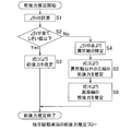
- FIG. 3 is a flowchart showing the longitudinal force estimation procedure of the longitudinal force estimation apparatus.
- the speed difference calculation means 26 obtains the vehicle speed difference ⁇ V obtained by the vehicle speed calculation means 25 between the wheels (step S1).
- the determination unit 27 determines whether or not all ⁇ V are equal to or less than the threshold value (step S2).
- ⁇ V is less than or equal to the threshold value (step S2: Yes)
- the normal-time front / rear force estimating means 28 estimates the front-rear force of the wheels 2 and 3 from equation (3) (step S3). Thereafter, this process is terminated.
- step S2 when the determination unit 27 determines that there is ⁇ V that is not equal to or less than the threshold value (step S2: No), the abnormal ring is specified as described with reference to Table 1 (step S4).
- the abnormal time longitudinal force estimating means 29 estimates the longitudinal force of three wheels other than the abnormal wheels from the equation (3) (step S5).
- the abnormal front-rear force estimating means 29 estimates the front-rear force of the abnormal wheel from equation (4) (step S6). Thereafter, this process is terminated.
- FIG. 4 shows an example in which torque loss is generated in only one right rear wheel during actual vehicle travel and the vehicle speed is estimated for each wheel.
- the normal-time front / rear force estimating means 28 and the abnormal-time front / rear force estimating means 29 give each inverter device 22 a command to temporarily equalize the drive torque applied to the independently driven wheels 2 and 3, for example, zero. In this case, the presence or absence of an abnormal wheel can be determined without depending on the friction coefficient of the road surface.
- the in-wheel motor drive device 7 is a so-called direct motor type in which a cycloid reducer, a planetary reducer, a two-axis parallel reducer, and other reducers can be applied. Also good.
- the vehicle is not limited to a four-wheel independent drive vehicle, and may be a two-wheel independent drive vehicle in which left and right wheels are driven independently.
- One of the front and rear wheels may be an on-board drive wheel that is driven by one motor, and the other left and right wheels may be driven independently.
- the vehicle may be applied not only to a four-wheeled vehicle but also to a three-wheeled vehicle, and drive wheels for independently driving left and right wheels of the tricycle.
Landscapes
- Engineering & Computer Science (AREA)
- Physics & Mathematics (AREA)
- Transportation (AREA)
- Mechanical Engineering (AREA)
- Chemical & Material Sciences (AREA)
- Combustion & Propulsion (AREA)
- Power Engineering (AREA)
- General Physics & Mathematics (AREA)
- Automation & Control Theory (AREA)
- Mathematical Physics (AREA)
- Electric Propulsion And Braking For Vehicles (AREA)
- Force Measurement Appropriate To Specific Purposes (AREA)
- Control Of Driving Devices And Active Controlling Of Vehicle (AREA)
Abstract
製造コストの低減を図ると共に、予期せぬトルク損失が発生しても、車輪に作用する前後力を精度良く推定することができる車両の前後力推定装置を提供する。独立して駆動する複数の車輪(2),(3)毎に車両速度を求める車両速度計算手段(25)と、求めた車両速度の差を車輪同士で互いに求める速度差計算手段(26)とを設ける。全ての車両速度の差が閾値以下の場合、全ての車輪(2),(3)につき、定められた運動方程式より各車輪(2),(3)の前後力を推定する正常時前後力推定手段(28)と、任意の車輪(2),(3)と他の車輪(2),(3)との車両速度の差が閾値より大の場合、任意の車輪(2),(3)を異常輪として、他の車輪(2),(3)の前後力を運動方程式より推定し、異常輪の前後力を、車両に働く前後力から他の車輪(2),(3)の前後力の輪を減じて推定する異常時前後力推定手段(29)とを設けた。
Description
本出願は、2014年5月21日出願の特願2014-104925の優先権を主張するものであり、その全体を参照により本願の一部をなすものとして引用する。
この発明は、例えば、インホイールモータ駆動装置などを搭載した左右独立駆動車の前後力を推定する車両の前後力推定装置に関する。
従来、車両の姿勢を制御して車両の走行安定性を向上させるため、車両の前後力を推定する技術が公知である。この車両の前後力を推定もしくは検出する手法として、以下に挙げる手法(1),(2)が提案されている。
(1)前後力の計算に使用される車輪の慣性モーメントが変化しても前後力を精度良く推定する手法(特許文献1)。具体的には、車輪の回転運動方程式に基づく以下の式を用いて、車輪の前後力に相当するトルクTfxcを計算する。
Tfxc=T+α・Ic・dω/dt
Tは車輪のトルク、dω/dtは車輪の角加速度、Icは車輪の慣性モーメント、αは慣性モーメントを実際値に一致させるための補正係数である。補正係数αを求めるのに、(dω/dt)=0となる時点において、車輪の前後力に相当するトルクの実際値の時間微分が0になるという関係を利用する。
Tfxc=T+α・Ic・dω/dt
Tは車輪のトルク、dω/dtは車輪の角加速度、Icは車輪の慣性モーメント、αは慣性モーメントを実際値に一致させるための補正係数である。補正係数αを求めるのに、(dω/dt)=0となる時点において、車輪の前後力に相当するトルクの実際値の時間微分が0になるという関係を利用する。
(2)車両のアンチロックブレーキ装置において、センサを用いて車輪または車軸周りのひずみを測定することにより、車輪に働く前後力を直接検出する手法(特許文献2)。
車輪の回転運動方程式に基づき車輪の前後力を計算する従来技術(1)では、駆動系を構成する部品、例えば、軸受、歯車などに異常が生じて、予期せぬトルク損失Tlossが発生すると、車輪の運動方程式は次式に置き換わる。
Tfxc=T-Tloss+α・Ic・dω/dt
しかし、発生したトルク損失Tlossを見積もることは困難であるため、上式より車輪の前後力に相当するTfxc、言い換えれば、車輪に作用する前後力を推定する精度は低下してしまう。
Tfxc=T-Tloss+α・Ic・dω/dt
しかし、発生したトルク損失Tlossを見積もることは困難であるため、上式より車輪の前後力に相当するTfxc、言い換えれば、車輪に作用する前後力を推定する精度は低下してしまう。
従来技術(2)の車輪の前後力を検出するセンサは一般に高価であり、車両の製造コストの増加につながるという問題がある。
この発明の目的は、製造コストの低減を図ると共に、予期せぬトルク損失が発生しても、車輪に作用する前後力を精度良く推定することができる車両の前後力推定装置を提供することである。
以下、この発明について、理解を容易にするために、便宜上実施形態の符号を参照して説明する。
この発明の車両の前後力推定装置24は、複数の車輪2,3を独立して駆動する駆動源4を有する車両1に搭載される車両1の前後力推定装置24であって、
前記車輪2,3毎にその車輪2,3の角速度を用いて車両速度を求める車両速度計算手段25と、
この車両速度計算手段25で求めた前記車輪毎の車両速度の差を車輪同士で互いに求める速度差計算手段26と、
この速度差計算手段26で求めた全ての車両速度の差が閾値以下または閾値未満の場合、全ての前記車輪2,3につき、定められた運動方程式より各車輪2,3の前後力を推定する正常時前後力推定手段28と、
任意の車輪2,3と他の車輪2,3との車両速度の差が閾値より大または閾値以上の場合、前記任意の車輪2,3を異常輪として、前記他の車輪2,3の前後力を前記運動方程式より推定し、前記異常輪の前後力を、車両1に働く前後力から前記他の車輪2,3の前後力の和を減じて推定する異常時前後力推定手段29とを設けた。
前記車両速度は、車輪2,3の回転速度と車両1のヨー角速度等から前記車輪2,3毎に推定される。
前記閾値は、例えば、実験やシミュレーション等の結果により定められる。
前記定められた運動方程式は、例えば、次のように表される。
I(dω/dt)=T-RF
Iは車輪の回転部の慣性モーメント、ωは車輪の角速度、Tは駆動トルク、Rは車輪の半径、Fは前後力を表す。
前記正常時前後力推定手段28と前記異常時前後力推定手段29との間において、前記「閾値以下」に対し前記「閾値より大」が対応し、前記「閾値未満」に対し前記「閾値以上」が対応する。
前記異常時前後力推定手段29は、車輪2,3が正常か異常かを判断する部分を含まなくても良く、特定された任意の車輪2,3を、他の車輪2,3とは異なる推定手段を用いて前後力を推定するために適用される。
前記車輪2,3毎にその車輪2,3の角速度を用いて車両速度を求める車両速度計算手段25と、
この車両速度計算手段25で求めた前記車輪毎の車両速度の差を車輪同士で互いに求める速度差計算手段26と、
この速度差計算手段26で求めた全ての車両速度の差が閾値以下または閾値未満の場合、全ての前記車輪2,3につき、定められた運動方程式より各車輪2,3の前後力を推定する正常時前後力推定手段28と、
任意の車輪2,3と他の車輪2,3との車両速度の差が閾値より大または閾値以上の場合、前記任意の車輪2,3を異常輪として、前記他の車輪2,3の前後力を前記運動方程式より推定し、前記異常輪の前後力を、車両1に働く前後力から前記他の車輪2,3の前後力の和を減じて推定する異常時前後力推定手段29とを設けた。
前記車両速度は、車輪2,3の回転速度と車両1のヨー角速度等から前記車輪2,3毎に推定される。
前記閾値は、例えば、実験やシミュレーション等の結果により定められる。
前記定められた運動方程式は、例えば、次のように表される。
I(dω/dt)=T-RF
Iは車輪の回転部の慣性モーメント、ωは車輪の角速度、Tは駆動トルク、Rは車輪の半径、Fは前後力を表す。
前記正常時前後力推定手段28と前記異常時前後力推定手段29との間において、前記「閾値以下」に対し前記「閾値より大」が対応し、前記「閾値未満」に対し前記「閾値以上」が対応する。
前記異常時前後力推定手段29は、車輪2,3が正常か異常かを判断する部分を含まなくても良く、特定された任意の車輪2,3を、他の車輪2,3とは異なる推定手段を用いて前後力を推定するために適用される。
この前後力推定装置24は、例えば、常時、以下の各計算を行い、定められた条件で前後力の推定を行う。前記定められた条件は、試験やシミュレーション等の結果により適宜定められる。この構成によると、車両速度計算手段25は、先ず車両速度を前記車輪2,3の各々毎に計算する。次に、速度差計算手段26は、前記車輪2,3の各々毎に求めた車両速度の差を計算する。求めた全ての車両速度の差が閾値以下または閾値未満の場合、全ての車輪2,3に大きなトルク損失が発生していないと考えられる。この場合、正常時前後力推定手段28は、全ての前記車輪2,3につき、定められた運動方程式より各車輪2,3の前後力を推定する。
任意の車輪2,3と他の車輪2,3との車両速度の差が閾値より大または閾値以上の場合、任意の車輪2,3に大きなトルク損失が発生していると考えられる。この場合、前記運動方程式は成立しなくなり、この運動方程式では、前記任意の車輪2,3の前後力を正しく推定できなくなる。ただし、前記他の車輪2,3の前後力は前記運動方程式より推定し得る。そこで、異常時前後力推定手段29は、車両1に働く前後力から前記他の車輪2,3の前後力の和を減じて、任意の車輪2,3の前後力を推定する。
前記車両1に働く前後力は、全ての車輪2,3に働く前後力の和に相当し、例えば、車両1の重量に車両の前後加速度を乗じて求められる。なお、トルク損失が大きくなるといった異常は、1輪毎に発生して複数輪同時に発生するとは考えにくい。よって、異常時において、異常時前後力推定手段29は、前述のように、他の車輪2,3の前後力だけでなく異常輪の前後力を精度良く推定し得る。また、正常時には、正常時前後力推定手段28も各車輪2,3の前後力を精度良く推定し得る。したがって、車輪2,3に予期せぬトルク損失が発生していても、車輪2,3の前後力を直接検出するセンサ等を用いることなく、各車輪2,3の前後力を精度良く推定し得る。また、車輪の前後力を直接検出する従来技術(2)よりも製造コストの低減を図れる。
前記正常時前後力推定手段28および前記異常時前後力推定手段29は、独立して駆動する各車輪2,3に与える駆動トルクを一時的に等しくする指令を、前記駆動源4を制御する制御手段22に与えるものとしても良い。このように各車輪2,3に与える駆動トルクを一時的に等しくすることで、異常輪の有無を判定し易くなる。
前記正常時前後力推定手段28および前記異常時前後力推定手段29は、独立して駆動する各車輪2,3に与える駆動トルクを一時的に零とする指令を、前記駆動源4を制御する制御手段22に与えるものとしても良い。この場合、路面の摩擦係数に依存せずに異常輪の有無を判定できる。
前記車両速度計算手段25は、前記車輪2,3毎に検出される角速度と、車両1のヨー角速度と、定められた車両固有のパラメータとに基づいて、前記車輪毎の車両速度を求めても良い。前記車両固有のパラメータは、例えば、車輪半径R、トレッドd等である。前記駆動源4は電動式のモータ4であっても良い。この場合、モータ4の電流を観測することで、駆動トルクを正確に把握することができる。前記駆動源4は、インホイールモータ駆動装置7を構成する前記モータ4であっても良い。
請求の範囲および/または明細書および/または図面に開示された少なくとも2つの構成のどのような組合せも、この発明に含まれる。特に、請求の範囲の各請求項の2つ以上のどのような組合せも、この発明に含まれる。
この発明は、添付の図面を参考にした以下の好適な実施形態の説明から、より明瞭に理解されるであろう。しかしながら、実施形態および図面は単なる図示および説明のためのものであり、この発明の範囲を定めるために利用されるべきものではない。この発明の範囲は添付の請求の範囲によって定まる。添付図面において、複数の図面における同一の符号は、同一または相当する部分を示す。
この発明の一の実施形態に係る車両の前後力推定装置を図1ないし図4と共に説明する。図1に示すように、この前後力推定装置が搭載される車両1として、例えば、左右の前輪(車輪)2,2および後輪(車輪)3,3が、それぞれ駆動源であるモータ4によって独立して駆動される四輪独立駆動車が適用される。各モータ4は、車輪用軸受5、および、モータ4の回転を減速して車輪用軸受5の図示外の回転側軌道輪に伝達する減速機6と共に、インホイールモータ駆動装置7を構成する。左右の前輪2,2は、転舵機構8により転舵可能であり、操舵入力手段であるハンドル9により転舵機構8を介して操舵される。
車両1の制御系について説明する。車両1の制御系は、メインのECU21と、各モータ4をそれぞれ駆動するインバータ装置22とを有する。ECU21は、車両全体の協調制御,統括制御を行う電気制御ユニットであり、プロセッサを有するコンピュータ、前記プロセッサで実行されるプログラムを有するROM(Read Only Memory)、およびRAM(Random Access Memory)やコプロセッサ(Co-Processor)等の他の電子回路により構成される。ECU21には、少なくともトルク分配手段23が設けられている。トルク分配手段23は、アクセルペダル13等のアクセル操作手段からの加速指令、およびブレーキペダル14等のブレーキ操作手段からの減速指令が入力され、前記加速指令と減速指令の差に応じて、ソフトウエアやハードウエアで実現されたLUT(Look Up Table)、およびソフトウエアのライブラリ(Library)に収められた所定の変換関数やそれに等価のハードウエア等を用いて、駆動指令を生成し、各モータ4に分配する。前記駆動指令は、例えば、トルク指令である。なお、アクセル操作手段およびブレーキ操作手段は、操作者がアクセルおよびブレーキを指示するための手段であれば、上記ペダル入力式に限られず、ボタン入力式、レバー入力式等であってもよい。
トルク分配手段23から分配して出力される駆動指令は、各輪2,3の各インバータ装置22に与えられる。各インバータ装置22は、図示外のバッテリの直流電力をモータ4の駆動用の交流電力に変換する図示外のインバータと、このインバータを制御するモータコントロール回路部(図示せず)とを有する。このモータコントロール回路部には、例えば、マイクロコンピュータおよび該マイクロコンピュータで実行されるモータ制御プログラムを有するROM等が含まれる。各インバータ装置22は、該モータ制御プログラムが実行され、与えられたトルク指令等の駆動指令に応じて、前記インバータを制御し、モータ4に与える電力を制御する。
前後力推定装置24は、前記構成を有する車両のECU21に設けられる。なお前後力推定装置24を、前記メインのECU21とは別のECUに設けても良い。前後力推定装置24は、車両速度計算手段25と、速度差計算手段26と、判定部27と、正常時前後力推定手段28と、異常時前後力推定手段29と、メモリ等の記憶手段30と、報知手段31とを有する。正常時前後力推定手段28および異常時前後力推定手段29は、各車輪2,3の前後力を推定するとき、例えば、独立して駆動する各車輪2,3に与える駆動トルクを一時的に等しくする指令を、各モータ4をそれぞれ制御するインバータ装置(制御手段)22に与える。
車両速度計算手段25は、車輪2,3の各々毎に次式で車両速度Vをそれぞれ求める。
Vj=Rωj±(d/2)r …(1)
Rは車輪半径、ωは車輪の角速度、dは前後輪のトレッド、rはヨー角速度を表す。式(1)の符号は、左側の車輪では正、右側の車輪では負とする。添え字jは車輪の番号を表す。例えば、添え字j=1が左前輪、j=2が右前輪、j=3が左後輪、j=4が右後輪を表す。車輪半径R、トレッドdは、車両固有のパラメータであり、例えば、記憶手段30に記憶されてこの記憶手段30から取得し得る。車両速度計算手段25は、ソフトウエアやハードウエアで実現されたLUT、およびソフトウエアのライブラリに収められた所定の変換関数やそれに等価のハードウエア等を用いて、上記式(1)を演算しうる回路または関数が構成されて、上記の各車両固有のパラメータの入力により車輪毎の車両速度を求める。
Vj=Rωj±(d/2)r …(1)
Rは車輪半径、ωは車輪の角速度、dは前後輪のトレッド、rはヨー角速度を表す。式(1)の符号は、左側の車輪では正、右側の車輪では負とする。添え字jは車輪の番号を表す。例えば、添え字j=1が左前輪、j=2が右前輪、j=3が左後輪、j=4が右後輪を表す。車輪半径R、トレッドdは、車両固有のパラメータであり、例えば、記憶手段30に記憶されてこの記憶手段30から取得し得る。車両速度計算手段25は、ソフトウエアやハードウエアで実現されたLUT、およびソフトウエアのライブラリに収められた所定の変換関数やそれに等価のハードウエア等を用いて、上記式(1)を演算しうる回路または関数が構成されて、上記の各車両固有のパラメータの入力により車輪毎の車両速度を求める。
角速度ωは、例えば、各車輪2,3に設けた回転センサ15より取得される。ヨー角速度rは、ヨー角速度センサより取得してもよいし、ハンドル9の操舵角を検出する操舵検出センサ11から演算により求めてもよい。演算により求める場合、具体的には、例えば、車両試験により、操舵角に対するヨー角速度rの伝達特性を予め求めておき、車両速度計算手段25は、求めた伝達特性に基づき、ソフトウエアやハードウエアで実現されたLUT、およびソフトウエアのライブラリに収められた所定の変換関数やそれに等価のハードウエア等を用いて回路または関数が構成されて、操舵検出センサ11で検出された操舵角から相応なヨー角速度rを求める。
速度差計算手段26は、ソフトウエアやハードウエアで実現されたLUT、およびソフトウエアのライブラリに収められた所定の減算関数やそれに等価のハードウエア等を用いて回路または関数が構成されて、車両速度計算手段25で求めた各車輪の車両速度間の差を求める。例えば、4番目の右後ろの車輪3の角速度より求めた車両速度を、他の車輪2,3の角速度より求めた車両速度と比較するときは、その車両速度の差を次式で計算する。
ΔVj4=Vj-V4(j=1~3) …(2)
ΔVj4=Vj-V4(j=1~3) …(2)
ここで表1に、各車輪2,3の車両速度の差と閾値との関係を示す。ここでは、後で説明する4番目の車輪3が異常輪と判定部27によって特定される場合の例を示す。

表1に示す車両速度の差ΔVについて、4番目の車輪3に関する式(2)と同様の計算を、他の1~3番目の車輪についても行う。判定部27は、閾値との比較の結果、車両速度の差ΔVの大きさに応じて次のA.またはB.のように、前後力推定手段を正常時前後力推定手段28または異常時前後力推定手段29から選択する。
A.(判定部27により、全ての車両速度の差が閾値以下と判定された場合)
この場合は4輪全てに大きなトルク損失が発生していないと考える。この場合、正常時前後力推定手段28が、全ての車輪2,3につき、定められた運動方程式より各車輪2,3の前後力を推定する。前記閾値は、記憶手段30に書換え可能に記憶される。正常時前後力推定手段28は、ソフトウエアやハードウエアで実現されたLUT、およびソフトウエアのライブラリに収められた所定の変換関数やそれに等価のハードウエア等を用いて、上記運動方程式を演算しうる回路または関数が構成されて、当該正常時の各車輪2,3の前後力Fを算出する。
この場合は4輪全てに大きなトルク損失が発生していないと考える。この場合、正常時前後力推定手段28が、全ての車輪2,3につき、定められた運動方程式より各車輪2,3の前後力を推定する。前記閾値は、記憶手段30に書換え可能に記憶される。正常時前後力推定手段28は、ソフトウエアやハードウエアで実現されたLUT、およびソフトウエアのライブラリに収められた所定の変換関数やそれに等価のハードウエア等を用いて、上記運動方程式を演算しうる回路または関数が構成されて、当該正常時の各車輪2,3の前後力Fを算出する。
図2は、この車両1の車輪2,3の運動モデルを示す図である。前記定められた運動方程式は、例えば、次のように表される。
I(dω/dt)=T-RF …(3)
Iは車輪2,3の回転部の慣性モーメント、ωは車輪2,3の角速度、Tは駆動トルク、Rは車輪2,3の半径、Fは前後力を表す。図2に示すように、慣性モーメントIと車輪2,3の半径Rは、車両固有のパラメータであり、例えば、記憶手段30に保存し、記憶手段30から容易に取得し得る。角速度ωは、例えば、各車輪2,3に設けた回転センサ15より取得し得る(図1参照)。
I(dω/dt)=T-RF …(3)
Iは車輪2,3の回転部の慣性モーメント、ωは車輪2,3の角速度、Tは駆動トルク、Rは車輪2,3の半径、Fは前後力を表す。図2に示すように、慣性モーメントIと車輪2,3の半径Rは、車両固有のパラメータであり、例えば、記憶手段30に保存し、記憶手段30から容易に取得し得る。角速度ωは、例えば、各車輪2,3に設けた回転センサ15より取得し得る(図1参照)。
また駆動源がモータ4であるため、図1に示すように、各モータ4に流れる電流を観測する電流検出手段32を設け、この電流検出手段32により電流を観測することでこの電流と比例関係にある駆動トルクTを正確に把握し得る。したがって、全ての車両速度の差が閾値以下と判定された場合、式(3)を用いて各車輪2,3の前後力を推定し得る。
B.(任意の車輪と他の車輪との車両速度の差が閾値より大と判定された場合)
例えば、表1の最右列の太枠内に示したように、設定した閾値εより車両速度の差ΔV14、ΔV24、ΔV34が大きいと判定部27で判定された場合、判定部27は、4番目の車輪3に大きなトルク損失が発生している、すなわち4番目の車輪3が異常輪であると特定する。このとき、前述の式(3)は成立しなくなり、前後力Fを正しく推定できなくなる。この場合、異常時前後力推定手段29が、次式(4)により、異常輪の前後力を推定する。但し、他の1~3番目の車輪2,3については、前記A.と同様に式(3)を使って、前後力Fを推定する。異常時前後力推定手段29は、ソフトウエアやハードウエアで実現されたLUT、およびソフトウエアのライブラリに収められた所定の変換関数やそれに等価のハードウエア等を用いて、式(3)および式(4)を演算しうる回路または関数が構成されて、当該異常時の車輪2,3の異常輪3および他の車輪2,3の前後力Fを算出する。
例えば、表1の最右列の太枠内に示したように、設定した閾値εより車両速度の差ΔV14、ΔV24、ΔV34が大きいと判定部27で判定された場合、判定部27は、4番目の車輪3に大きなトルク損失が発生している、すなわち4番目の車輪3が異常輪であると特定する。このとき、前述の式(3)は成立しなくなり、前後力Fを正しく推定できなくなる。この場合、異常時前後力推定手段29が、次式(4)により、異常輪の前後力を推定する。但し、他の1~3番目の車輪2,3については、前記A.と同様に式(3)を使って、前後力Fを推定する。異常時前後力推定手段29は、ソフトウエアやハードウエアで実現されたLUT、およびソフトウエアのライブラリに収められた所定の変換関数やそれに等価のハードウエア等を用いて、式(3)および式(4)を演算しうる回路または関数が構成されて、当該異常時の車輪2,3の異常輪3および他の車輪2,3の前後力Fを算出する。

mは車両重量、axは車両の前後加速度、maxは車両に働く前後力(4輪に働く前後力の和)に相当する。車両重量mは、例えば、記憶手段30に保存しておき、記憶手段30から取り出して取得する。前後加速度axは、例えば、車両1に取り付けた加速度センサ33より取得する。なおトルク損失が大きくなるといった異常は、1輪毎に発生して複数輪同時に発生するとは考えにくい。よって、B.の異常時前後力推定手段29により、異常が生じた車輪2,3の前後力を推定し得る。したがって、車輪2,3に予期せぬトルク損失が発生していても、車輪2,3の前後力を直接検出するセンサ等を用いることなく、各車輪2,3の前後力を精度良く推定し得る。このため、例えば、車輪の前後力を直接検出する従来技術よりも製造コストの低減を図れる。
報知手段31は、異常輪があると判定部27が判定したときに、例えば、異常が発生した車輪2,3を運転席のモニター等(図示せず)に出力して、運転者の注意を喚起する。トルク損失が大きくなる異常の原因は、例えば、インホイールモータ駆動装置7の構成部品(歯車や軸受)等の異常に起因する。
図3は、前後力推定装置の前後力推定手順を示すフローチャートである。以後、図1,図2も適宜参照しつつ説明する。例えば、この車両1の電源を投入後、前後力の推定を開始し、速度差計算手段26は、車両速度計算手段25で求めた車両速度の差ΔVを各車輪間で求める(ステップS1)。次に、ΔVが全て閾値以下か否かを判定部27が判定する(ステップS2)。ΔVが全て閾値以下のとき(ステップS2:Yes)、正常時前後力推定手段28は、式(3)より各車輪2,3の前後力を推定する(ステップS3)。その後、本処理を終了する。
ステップS2において、判定部27は、閾値以下でないΔVがあると判定したとき(ステップS2:No)、表1を用いて説明したように異常輪の特定を行う(ステップS4)。次に、正常時前後力推定手段28に代わって、異常時前後力推定手段29は、式(3)より異常輪以外の三輪の前後力を推定する(ステップS5)。次に、異常時前後力推定手段29は、式(4)より異常輪の前後力を推定する(ステップS6)。その後本処理を終了する。
実際の車両走行中に右後輪の1輪だけにトルク損失を発生させ、車輪毎に車両速度を推定した例を図4に示す。異常輪の有無を判定するために、駆動輪に同じ駆動トルクを加えて式(1)より車輪毎の車両速度を計算するのが適切であるが、より簡単な方法としては、駆動トルクを与えずに惰性で走行しているときの車両速度を調べるのが良い。正常時前後力推定手段28および異常時前後力推定手段29は、独立して駆動する各車輪2,3に与える駆動トルクを一時的に等しく、例えば零とする指令を各インバータ装置22に与える。この場合、路面の摩擦係数に依存せずに異常輪の有無を判定できる。
インホイールモータ駆動装置7においては、サイクロイド式の減速機、遊星減速機、2軸並行減速機、その他の減速機を適用可能であり、また、減速機を採用しない、所謂ダイレクトモータタイプであってもよい。
車両は四輪独立駆動車に限定されず、左右輪が独立して駆動する二輪独立駆動車であっても良い。前後輪のいずれか一方を1モータで駆動するオンボード式の駆動輪とし、いずれか他方の左右輪を独立して駆動する駆動輪としても良い。また、車両を四輪車だけでなく三輪車に適用し、この三輪車の左右輪を独立して駆動する駆動輪としても良い。
以上のとおり、図面を参照しながら好適な実施形態を説明したが、当業者であれば、本件明細書を見て、自明な範囲内で種々の変更および修正を容易に想定するであろう。したがって、そのような変更および修正は、請求の範囲から定まる発明の範囲内のものと解釈される。
1…車両
2…前輪(車輪)
3…後輪(車輪)
4…モータ(駆動源)
7…インホイールモータ駆動装置
22…インバータ装置(制御手段)
24…前後力推定装置
25…車両速度計算手段
26…速度差計算手段
28…正常時前後力推定手段
29…異常時前後力推定手段
2…前輪(車輪)
3…後輪(車輪)
4…モータ(駆動源)
7…インホイールモータ駆動装置
22…インバータ装置(制御手段)
24…前後力推定装置
25…車両速度計算手段
26…速度差計算手段
28…正常時前後力推定手段
29…異常時前後力推定手段
Claims (6)
- 複数の車輪を独立して駆動する駆動源を有する車両に搭載される車両の前後力推定装置であって、
前記車輪毎にその車輪の角速度を用いて車両速度を求める車両速度計算手段と、
この車両速度計算手段で求めた前記車輪毎の車両速度の差を車輪同士で互いに求める速度差計算手段と、
この速度差計算手段で求めた全ての車両速度の差が閾値以下または閾値未満の場合、全ての前記車輪につき、定められた運動方程式より各車輪の前後力を推定する正常時前後力推定手段と、
任意の車輪と他の車輪との車両速度の差が閾値より大または閾値以上の場合、前記任意の車輪を異常輪として、前記他の車輪の前後力を前記運動方程式より推定し、前記異常輪の前後力を、車両に働く前後力から前記他の車輪の前後力の和を減じて推定する異常時前後力推定手段と、
を設けた車両の前後力推定装置。 - 請求項1記載の車両の前後力推定装置において、前記正常時前後力推定手段および前記異常時前後力推定手段は、独立して駆動する各車輪に与える駆動トルクを一時的に等しくする指令を、前記駆動源を制御する制御手段に与える車両の前後力推定装置。
- 請求項1記載の車両の前後力推定装置において、前記正常時前後力推定手段および前記異常時前後力推定手段は、独立して駆動する各車輪に与える駆動トルクを一時的に零とする指令を、前記駆動源を制御する制御手段に与える車両の前後力推定装置。
- 請求項1ないし請求項3のいずれか1項に記載の車両の前後力推定装置において、前記車両速度計算手段は、前記車輪毎に検出される角速度と、車両のヨー角速度と、定められた車両固有のパラメータとに基づいて、前記車輪毎の車両速度を求める車両の前後力推定装置。
- 請求項1ないし請求項4のいずれか1項に記載の車両の前後力推定装置において、前記駆動源は電動式のモータである車両の前後力推定装置。
- 請求項5記載の車両の前後力推定装置において、前記駆動源は、インホイールモータ駆動装置を構成する前記モータである車両の前後力推定装置。
Applications Claiming Priority (2)
| Application Number | Priority Date | Filing Date | Title |
|---|---|---|---|
| JP2014104925A JP6266436B2 (ja) | 2014-05-21 | 2014-05-21 | 車両の前後力推定装置 |
| JP2014-104925 | 2014-05-21 |
Publications (1)
| Publication Number | Publication Date |
|---|---|
| WO2015178274A1 true WO2015178274A1 (ja) | 2015-11-26 |
Family
ID=54553947
Family Applications (1)
| Application Number | Title | Priority Date | Filing Date |
|---|---|---|---|
| PCT/JP2015/063778 Ceased WO2015178274A1 (ja) | 2014-05-21 | 2015-05-13 | 車両の前後力推定装置 |
Country Status (2)
| Country | Link |
|---|---|
| JP (1) | JP6266436B2 (ja) |
| WO (1) | WO2015178274A1 (ja) |
Citations (2)
| Publication number | Priority date | Publication date | Assignee | Title |
|---|---|---|---|---|
| JP2007252045A (ja) * | 2006-03-14 | 2007-09-27 | Nissan Motor Co Ltd | 車両用駆動制御装置、自動車及び車両用駆動制御方法 |
| JP2009198185A (ja) * | 2008-02-19 | 2009-09-03 | Toyota Motor Corp | 車両位置姿勢推測装置 |
Family Cites Families (4)
| Publication number | Priority date | Publication date | Assignee | Title |
|---|---|---|---|---|
| JPH03220056A (ja) * | 1988-10-13 | 1991-09-27 | Nippon Denshi Kogyo Kk | 路面摩擦力検出装置及び路面摩擦係数検出装置並びに車両のアンチロックブレーキ装置 |
| JP4697430B2 (ja) * | 2006-01-19 | 2011-06-08 | 株式会社アドヴィックス | タイヤ前後力推定装置 |
| JP5527081B2 (ja) * | 2010-07-23 | 2014-06-18 | 日産自動車株式会社 | 電動車両の駆動力推定装置 |
| JP2014043118A (ja) * | 2012-08-24 | 2014-03-13 | Ntn Corp | インホイールモータ駆動装置およびその異常時処理装置 |
-
2014
- 2014-05-21 JP JP2014104925A patent/JP6266436B2/ja not_active Expired - Fee Related
-
2015
- 2015-05-13 WO PCT/JP2015/063778 patent/WO2015178274A1/ja not_active Ceased
Patent Citations (2)
| Publication number | Priority date | Publication date | Assignee | Title |
|---|---|---|---|---|
| JP2007252045A (ja) * | 2006-03-14 | 2007-09-27 | Nissan Motor Co Ltd | 車両用駆動制御装置、自動車及び車両用駆動制御方法 |
| JP2009198185A (ja) * | 2008-02-19 | 2009-09-03 | Toyota Motor Corp | 車両位置姿勢推測装置 |
Also Published As
| Publication number | Publication date |
|---|---|
| JP2015220939A (ja) | 2015-12-07 |
| JP6266436B2 (ja) | 2018-01-24 |
Similar Documents
| Publication | Publication Date | Title |
|---|---|---|
| CN105899421B (zh) | 四轮独立驱动车的一轮失灵时车辆控制装置 | |
| JP6440971B2 (ja) | 左右独立駆動車のトラクション制御機能付き駆動制御装置 | |
| CN105377622B (zh) | 电动汽车的滑移控制装置 | |
| JP6223717B2 (ja) | 電気自動車のスリップ制御装置 | |
| CN106794777B (zh) | 防止车辆的横向滑移的控制装置 | |
| US10661657B2 (en) | Slip control device | |
| JP6502074B2 (ja) | 車両の制駆動力制御装置 | |
| CN110650862A (zh) | 电动车辆的控制装置、电动车辆的控制系统及电动车辆的控制方法 | |
| JP5707791B2 (ja) | タイヤ接地状態推定装置 | |
| CN107848526A (zh) | 车辆转弯控制装置 | |
| JP2010166740A (ja) | 電気自動車の制御装置 | |
| JP4230961B2 (ja) | 推定装置およびそれを用いた車両運動制御装置 | |
| CN105531144A (zh) | 电动汽车的滑移控制装置 | |
| WO2012011437A1 (ja) | 電動車両のトルク異常判定装置 | |
| JP6396188B2 (ja) | 車両の車体速度推定装置 | |
| CN118613384A (zh) | 移动体的控制系统、程序 | |
| JP6267440B2 (ja) | 車両制御装置 | |
| JP5540641B2 (ja) | タイヤ状態推定装置 | |
| JP6585446B2 (ja) | 車両の制駆動力制御装置 | |
| JP6266436B2 (ja) | 車両の前後力推定装置 | |
| JP2021109454A (ja) | 車両の旋回制御装置 | |
| JP2016127713A (ja) | 四輪独立駆動車における一輪失陥時車両制御装置 | |
| JP2019043258A (ja) | 四輪駆動車の車輪荷重推定方法 | |
| JP2016094139A (ja) | 四輪駆動車両の車両速度推定装置および制御装置 | |
| JP7816319B2 (ja) | 車両の制御装置 |
Legal Events
| Date | Code | Title | Description |
|---|---|---|---|
| 121 | Ep: the epo has been informed by wipo that ep was designated in this application |
Ref document number: 15796075 Country of ref document: EP Kind code of ref document: A1 |
|
| NENP | Non-entry into the national phase |
Ref country code: DE |
|
| 122 | Ep: pct application non-entry in european phase |
Ref document number: 15796075 Country of ref document: EP Kind code of ref document: A1 |